

Bosch ZBR42-3A, ZWB28-3A, ZBR21-3A, ZBR28-3A, ZWB35-3A Installation And Service Instructions Manual
...
WARNING:
Improper installation, set-up, modification, operation or maintenance
of the heating system can cause personal injury and property damage.
Follow these instructions precisely.
If you require assistance or further information, contact a trained and
certified installer or the gas supply company.
WARNING:
The operating instructions are part of the technical documents that
must be handed over to the owner or operator of the heating system.
Explain to the owner or operator how to use the heating system using
the operating instructions. Make sure that they are familiar with all
required information for the safe and proper operation of the heating
system.
NOTICE:
In Massachusetts, this appliance must be installed by a licensed
plumber or gas fitter.
These instructions are available in English and French.
Please keep these instructions for future reference.
6 720 806 992-00-1O
Residential Gas Condensing Boiler
Greenstar
ZBR16-3A... | ZBR21-3A... | ZBR28-3A... | ZBR35-3A... | ZBR42-3A... | ZWB28-3A... | ZWB35-3A... | ZWB42-3A...
Installation and Service Instructions for Contractors
6 720 806 992 (2015/03) CA/US

2 | Contents
Contents
1 Key to symbols and safety instructions . . . . . . . . . . . . . . . . . . 3
1.1 Key to symbols . . . . . . . . . . . . . . . . . . . . . . . . . . . . . . . . . 3
1.2 General safety instructions . . . . . . . . . . . . . . . . . . . . . . . 4
2 Scope of delivery . . . . . . . . . . . . . . . . . . . . . . . . . . . . . . . . . . . . . 5
2.1 ZBR - Residential boiler for space heating and l
oading of indirect fired DHW tanks . . . . . . . . . . . . . . . . . 5
2.2 ZWB - Residential combi boiler for space heating
and DHW generation . . . . . . . . . . . . . . . . . . . . . . . . . . . . 6
3 Information about the appliance . . . . . . . . . . . . . . . . . . . . . . . . 7
3.1 Proper use . . . . . . . . . . . . . . . . . . . . . . . . . . . . . . . . . . . . . 7
3.2 Overview of boiler types . . . . . . . . . . . . . . . . . . . . . . . . . 7
3.3 Rating plate . . . . . . . . . . . . . . . . . . . . . . . . . . . . . . . . . . . . 7
3.4 Appliance description . . . . . . . . . . . . . . . . . . . . . . . . . . . 7
3.5 Accessories . . . . . . . . . . . . . . . . . . . . . . . . . . . . . . . . . . . . 8
3.6 Product dimensions and minimum clearances . . . . . . . . 9
3.7 Appliance layout heating boiler ZBR..-3A . . . . . . . . . . . 10
3.8 Appliance layout combi boiler ZWB..-3A . . . . . . . . . . . 12
3.9 Electrical wiring heating boiler ZBR..-3A . . . . . . . . . . . 14
3.10 Electrical wiring combi boiler ZWB..-3A . . . . . . . . . . . . 16
3.11 Technical data heating boiler ZBR16-3A... . . . . . . . . . . 18
3.12 Technical data heating boiler ZBR21-3A... . . . . . . . . . . 19
3.13 Technical data heating boiler ZBR28-3A... . . . . . . . . . . 20
3.14 Technical data heating boiler ZBR35-3A... . . . . . . . . . . 21
3.15 Technical data heating boiler ZBR42-3A... . . . . . . . . . . 22
3.16 Technical data combi boiler ZWB28-3A... . . . . . . . . . . 23
3.17 Technical data combi boiler ZWB35-3A... . . . . . . . . . . 24
3.18 Technical data combi boiler ZWB42-3A... . . . . . . . . . . 25
3.19 Condensate composition . . . . . . . . . . . . . . . . . . . . . . . . 26
4 Regulations . . . . . . . . . . . . . . . . . . . . . . . . . . . . . . . . . . . . . . . . . 26
4.1 Compliance with standards and regulations . . . . . . . . . 26
4.2 Operating limits of the boiler . . . . . . . . . . . . . . . . . . . . . 26
4.3 Additional regulations for installation
in Massachusetts . . . . . . . . . . . . . . . . . . . . . . . . . . . . . . 27
5 Common Applications of ZBR boilers . . . . . . . . . . . . . . . . . . . 28
5.1 Multiple zones using zone valves with DHW . . . . . . . . . 28
5.2 Multiple zones using circulators with DHW . . . . . . . . . . 30
6 Installation . . . . . . . . . . . . . . . . . . . . . . . . . . . . . . . . . . . . . . . . . . 32
6.1 Notes on installation and operation . . . . . . . . . . . . . . . . 32
6.1.1 Notes on installation and operation . . . . . . . . . . . . . . . . 32
6.1.2 Other important information . . . . . . . . . . . . . . . . . . . . . 33
6.2 Comparing the size of the integrated expansion
vessel . . . . . . . . . . . . . . . . . . . . . . . . . . . . . . . . . . . . . . . 33
6.3 ZBR..-3A appliances (heating boilers): Selecting an
expansion vessel . . . . . . . . . . . . . . . . . . . . . . . . . . . . . . 34
6.4 Selecting the installation location . . . . . . . . . . . . . . . . . 34
6.5 Pre-installing pipes . . . . . . . . . . . . . . . . . . . . . . . . . . . . . 34
6.6 Mounting the appliance . . . . . . . . . . . . . . . . . . . . . . . . . 36
6.7 Installing a low water cut off (LWCO) . . . . . . . . . . . . . . 36
6.8 Connecting flue gas accessories . . . . . . . . . . . . . . . . . . 37
6.8.1 Installation of the exhaust and air intake system . . . . . 38
6.8.2 Approved examples of horizontal and vertical
venting installation . . . . . . . . . . . . . . . . . . . . . . . . . . . . 42
6.8.3 Vent and combustion air pipe lengths . . . . . . . . . . . . . . 44
6.9 Testing gas and water connections for leaks . . . . . . . . 45
7 Making the electrical connections . . . . . . . . . . . . . . . . . . . . . . 45
7.1 General notes . . . . . . . . . . . . . . . . . . . . . . . . . . . . . . . . . 45
7.2 Low voltage electrical connections in the
Heatronic boiler control . . . . . . . . . . . . . . . . . . . . . . . . 46
7.2.1 Open the Heatronic boiler control . . . . . . . . . . . . . . . . . 46
7.2.2 Connecting the outdoor temperature sensor . . . . . . . . 46
7.2.3 Connecting the DHW tank temperature sensor
(only heating boiler ZBR..-3A) . . . . . . . . . . . . . . . . . . . 47
7.2.4 Connecting additional accessories . . . . . . . . . . . . . . . . 47
7.3 Electrical connections in the junction box (120 VAC) . 48
7.3.1 Mounting rails for junction box . . . . . . . . . . . . . . . . . . . 48
7.3.2 Connecting an external heating zone pump or
DHW recirculation pump . . . . . . . . . . . . . . . . . . . . . . . . 48
7.3.3 DHW tank loading pump or 3-way valve with
spring return (only heating boiler ZBR..-3A) . . . . . . . . 49
7.3.4 Connecting mains power supply . . . . . . . . . . . . . . . . . . 49
7.4 Connecting the LWCO device . . . . . . . . . . . . . . . . . . . . 50
8 Commissioning . . . . . . . . . . . . . . . . . . . . . . . . . . . . . . . . . . . . . . 51
8.1 Before operating the appliance . . . . . . . . . . . . . . . . . . . 51
8.2 Switching the appliance ON/OFF . . . . . . . . . . . . . . . . . 52
8.3 Setting up space heating . . . . . . . . . . . . . . . . . . . . . . . . 52
8.4 Programming the FW 200 heating control unit . . . . . . 52
8.5 FW 200 heating control quick start . . . . . . . . . . . . . . . . 53
8.5.1 Setting date and time . . . . . . . . . . . . . . . . . . . . . . . . . . . 53
8.5.2 Setting constant heating (no night set back) . . . . . . . . 53
8.5.3 Setting type of heating system . . . . . . . . . . . . . . . . . . . 53
8.5.4 Adjusting warm weather shut down (WWSD) . . . . . . . 54
8.5.5 Resetting all settings (for installers only) . . . . . . . . . . . 54
8.6 After commissioning . . . . . . . . . . . . . . . . . . . . . . . . . . . 54
8.7 ZBR..-3A appliances (heating boilers) with
DHW tank: Setting the DHW temperature . . . . . . . . . . 55
8.8 ZWB..-3A appliances (combi boilers):
Setting the DHW temperature . . . . . . . . . . . . . . . . . . . 55
8.9 Setting manual summer mode . . . . . . . . . . . . . . . . . . . . 55
8.10 Setting frost protection . . . . . . . . . . . . . . . . . . . . . . . . . 56
8.11 Activating the key pad lock . . . . . . . . . . . . . . . . . . . . . . 56
Greenstar6 720 806 992 (2015/03)
Key to symbols and safety instructions | 3
9 ZBR..-3A appliances (heating boiler) with DHW tank:
Thermal disinfection . . . . . . . . . . . . . . . . . . . . . . . . . . . . . . . . . 56
10 Boiler circulator . . . . . . . . . . . . . . . . . . . . . . . . . . . . . . . . . . . . . 57
10.1 Pump anti-seize protection . . . . . . . . . . . . . . . . . . . . . . 57
10.2 Changing the pump curve of the boiler pump . . . . . . . 57
11 Heatronic boiler control settings . . . . . . . . . . . . . . . . . . . . . . . 58
11.1 Guideline to service functions . . . . . . . . . . . . . . . . . . . . 58
11.2 Overview of the service functions . . . . . . . . . . . . . . . . . 58
11.2.1 First service level (press and hold the service
button until it lights up) . . . . . . . . . . . . . . . . . . . . . . . . 58
11.2.2 Second service level (at first service level, service
button lights up, press ECO button and key pad
lock button simultaneously until 8.A appears) . . . . . . 59
11.3 Description of the service functions . . . . . . . . . . . . . . . 59
11.3.1 First service level . . . . . . . . . . . . . . . . . . . . . . . . . . . . . . 59
11.3.2 Second service level . . . . . . . . . . . . . . . . . . . . . . . . . . . 63
12 Gas type conversion . . . . . . . . . . . . . . . . . . . . . . . . . . . . . . . . . 65
12.1 Converting to a different gas type . . . . . . . . . . . . . . . . . 65
12.2 Installation location higher than 2,000 feet
(610 m) above sea level . . . . . . . . . . . . . . . . . . . . . . . . 65
12.3 Setting the gas-air ratio (CO
or O2) . . . . . . . . . . . . . . . 66
2
12.4 Dynamic gas pressure test . . . . . . . . . . . . . . . . . . . . . . 67
13 Flue gas test . . . . . . . . . . . . . . . . . . . . . . . . . . . . . . . . . . . . . . . . 68
13.1 Emissions test button . . . . . . . . . . . . . . . . . . . . . . . . . . 68
13.2 Measuring CO content of flue gas . . . . . . . . . . . . . . . . . 68
14 Environmental responsibility/disposal . . . . . . . . . . . . . . . . . . 68
15 Inspection and maintenance . . . . . . . . . . . . . . . . . . . . . . . . . . 68
15.1 Description of various steps . . . . . . . . . . . . . . . . . . . . . 69
15.1.1 Calling up the latest fault (service function 6.A) . . . . . 69
15.1.2 Fresh water filter (only combi boiler ZWB..-3A) . . . . . 69
15.1.3 Plate type heat exchanger
(only combi boiler ZWB..-3A) . . . . . . . . . . . . . . . . . . . . 69
15.1.4 Checking the electrodes . . . . . . . . . . . . . . . . . . . . . . . . 70
15.1.5 Burner servicing . . . . . . . . . . . . . . . . . . . . . . . . . . . . . . . 71
15.1.6 Heat exchanger block inspection and cleaning . . . . . . 71
15.1.7 Condensate trap cleaning . . . . . . . . . . . . . . . . . . . . . . . 73
15.1.8 Checking the mixer diaphragm . . . . . . . . . . . . . . . . . . . 73
15.1.9 Expansion vessel . . . . . . . . . . . . . . . . . . . . . . . . . . . . . . 73
15.1.10Setting the boiler water pressure . . . . . . . . . . . . . . . . . 73
15.1.11Testing system water quality . . . . . . . . . . . . . . . . . . . . . 73
15.1.12Inspecting electrical wiring . . . . . . . . . . . . . . . . . . . . . . 73
15.2 Checklist for inspection and maintenance . . . . . . . . . . 74
16 Readings on the display . . . . . . . . . . . . . . . . . . . . . . . . . . . . . . 75
17 Faults . . . . . . . . . . . . . . . . . . . . . . . . . . . . . . . . . . . . . . . . . . . . . . 76
17.1 Troubleshooting . . . . . . . . . . . . . . . . . . . . . . . . . . . . . . . 76
17.2 Faults that are shown on the display . . . . . . . . . . . . . . 77
17.3 Faults that are not shown on the display . . . . . . . . . . . 79
17.4 Check sensor values . . . . . . . . . . . . . . . . . . . . . . . . . . . 80
17.4.1 Outdoor temperature sensor . . . . . . . . . . . . . . . . . . . . 80
17.4.2 Additional supply temperature limiter . . . . . . . . . . . . . 80
17.4.3 Supply temperature sensor, External supply
temperature sensor, DHW tank temperature
sensor, DHW temperature sensor . . . . . . . . . . . . . . . . 80
17.5 Replacement code plug . . . . . . . . . . . . . . . . . . . . . . . . . 80
18 Commissioning log for the appliance . . . . . . . . . . . . . . . . . . . 81
19 Spare parts . . . . . . . . . . . . . . . . . . . . . . . . . . . . . . . . . . . . . . . . . 83
Index . . . . . . . . . . . . . . . . . . . . . . . . . . . . . . . . . . . . . . . . . . . . . . 99
1 Key to symbols and safety instructions
1.1 Key to symbols
Warnings
Warnings in this document are identified by a warning
triangle printed against a grey background.
Keywords at the start of a warning indicate the type and
seriousness of the ensuing risk if measures to prevent
the risk are not taken.
The following keywords are defined and can be used in this document:
• DANGER indicates a hazardous situation which, if not avoided, will
result in death or serious injury.
• WARNING indicates a hazardous situation which, if not avoided,
could result in death or serious injury.
• CAUTION indicates a hazardous situation which, if not avoided,
could result in minor to moderate injury.
• NOTICE is used to address practices not related to personal injury.
Important information
Important information for the proper use of the boiler is
also provided in this manual. You will find the
information with a symbol shown on the left and
bordered by horizontal lines above and below the text.
Additional symbols
Symbol Explanation
▶ Sequence of steps
Cross-reference to other points in this document or to other
documents
• Listing/list entry
– Listing/list entry (2nd level)
Table 1
6 720 806 992 (2015/03)Greenstar

4 | Key to symbols and safety instructions
1.2 General safety instructions
If you hear gas leaking
▶ Leave the building immediately.
▶ Prevent others from entering the building.
▶ Notify the police and fire department from outside the building.
▶ From outside the building, call the gas supply company and a trained
and certified installer or service company.
If you smell gas
▶ Turn off the gas shut-off valve.
▶ Open windows and doors
▶ Do not touch any electrical switch, telephone, and do not use outlets.
▶ Extinguish all open flames.
▶ Do not smoke!
▶ Do not use lighters!
▶ Warn all occupants of the building that they need to leave the building.
▶ Do not ring doorbells!
▶ Notify the police and fire department from outside the building.
▶ From outside the building, call the gas supply company and a trained
and certified installer or service company.
If you smell flue gas
▶ Switch off the heating system by shutting off the emergency shut-off
switch.
▶ Open windows and doors.
▶ Call a trained and certified installer or service company.
DANGER: Risk of fatal injury from failing to consider your own
safety!
▶ Never risk your own life. Your own safety must always take the highest
priority
NOTICE: Risk of appliance damage from improper operation of the
boiler!
▶ Only use the boiler for its intended purpose.
▶ Only operate the boiler if it has been installed and maintained per the
instructions provided in the Installation Manual.
▶ Do not attempt to operate an appliance if any part of it is not in
working order or is damaged.
▶ Use only original spare parts! The use of parts not supplied by the
manufacturer may cause damage to the boiler, other property and
personal injury. Also, boiler damage caused by the use of
unauthorized parts is not covered by the warranty.
DANGER: Risk of fire when soldering and brazing!
▶ Take appropriate protective measures when soldering and brazing
around combustible and flammable material.
NOTICE:
▶ The installation must comply with all applicable national, state, and
local codes, rules, and regulations.
▶ The operator is responsible for the operational safety and regulatory
compliance of the heating system.
▶ In the Commonwealth of Massachusetts, the appliance must be
installed by a licensed plumber or gas fitter.
DANGER: Risk of personal injury or death from flue gas poisoning!
▶ Do not install a thermostatic flue gas damper downstream of the draft
hood.
▶ Do not tamper with, remove, or attempt to repair the blocked vent
switch.
▶ When replacing the blocked vent switch, install the new part in the
original location.
▶ A blocked vent switch tripping more than once indicates a problem
with the venting system or chimney which must be repaired
immediately.
▶ Ensure none of the vent pipes and chimneys are damaged or blocked.
▶ Connect only one appliance to each venting system or chimney.
▶ The venting system must not feed into or route through another air
extraction duct.
▶ The venting system must be inspected annually. All parts that show
any signs of damage or corrosion must be replaced.
▶ Never close off or reduce the size of the combustion air openings.
▶ The boiler must not be operated until any obstructions have been
removed.
DANGER: Risk of personal injury or death from explosion!
▶ Work on gas components may only be carried out by a trained and
certified installer or service company.
▶ Appliance installation, the connection of gas and vent piping, initial
commissioning, electrical connections, and service and maintenance
must only be carried out by a trained and certified installer or service
company.
DANGER: Risk of personal injury or death from fire!
▶ Do not use flammable or combustible material in the boiler room.
▶ It is recommended not to store any items within 16 inches (415mm)
of the appliance
CAUTION: Appliance damage from contaminated combustion air!
▶ Keep the combustion air free of corrosive substances, e.g.
halogenated hydrocarbons from painting operations or beauty
salons.
▶ Keep combustion air free from dust and lint, e.g. from laundry or
agricultural operations.
▶ If clean room air is not available, fresh outdoor combustion air must be
provided
DANGER: Risk of personal injury or death from electric shock.
▶ Before removing the front panel, disconnect the heating system from
the electrical power supply by shutting off the emergency shutoff
switch or the heating system circuit breaker.
▶ It is not enough to switch off the control panel. Power to the panel
must be disconnected! Ensure that the power is not restored
unintentionally by following proper lock out/tag out procedures.
▶ Only qualified electricians are permitted to carry out electrical work.
DANGER: Safety devices!
▶ Never shut off safety valves!
▶ Hot water may escape from the safety valve at any time when the
appliance is running.
DANGER: Risk of personal injury or death after a flood!
▶ Do not attempt to operate an appliance if any part of it has been under
water.
▶ An appliance that was subject to flooding must be replaced.
Greenstar6 720 806 992 (2015/03)
NOTICE:
▶ Upon completion of the installation, these instructions should be
handed to the owner and operator of the appliance.
▶ The installer must instruct the owner and operator on the functionality
of the components and the proper operation of the boiler and the
heating system.
▶ The boiler must be serviced annually including the main burner,
ignition burner, the entire venting system, and the combustion air
supply. All parts that show any signs of damage or corrosion must be
replaced.
1
2
3
Scope of delivery | 5
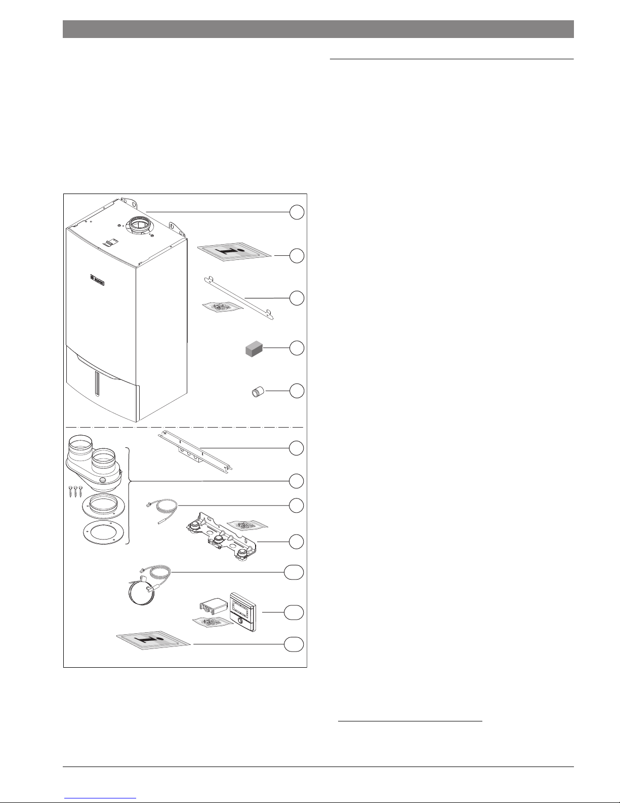
2 Scope of delivery
2.1 ZBR - Residential boiler for space heating and loading
of indirect fired DHW tanks
Contents of package 1:
[1] Gas condensing boiler
[2] Set of documents for appliance
[3] Mounting bracket with mounting kit
[4] Gas conversion kit
[5] Adapter for connection of a LWCO
10
11
4
5
6
7
8
Contents of package 2:
[6] Rail with connection box
[7] Flue adapter
[8] DHW tank temperature sensor (NTC)
[9] Hydraulics connection plate with mounting kit
[10] External supply temperature sensor (NTC)
[11] Outdoor reset control FW 200 with mounting kit and outdoor
temperature sensor
[12] Set of documents for outdoor reset control FW 200
1)
9
Fig. 1 Scope of delivery heating boiler ZBR..-3A
12
6 720 641 933-22.2O
1) Concentric vent kit available as accessory.
6 720 806 992 (2015/03)Greenstar
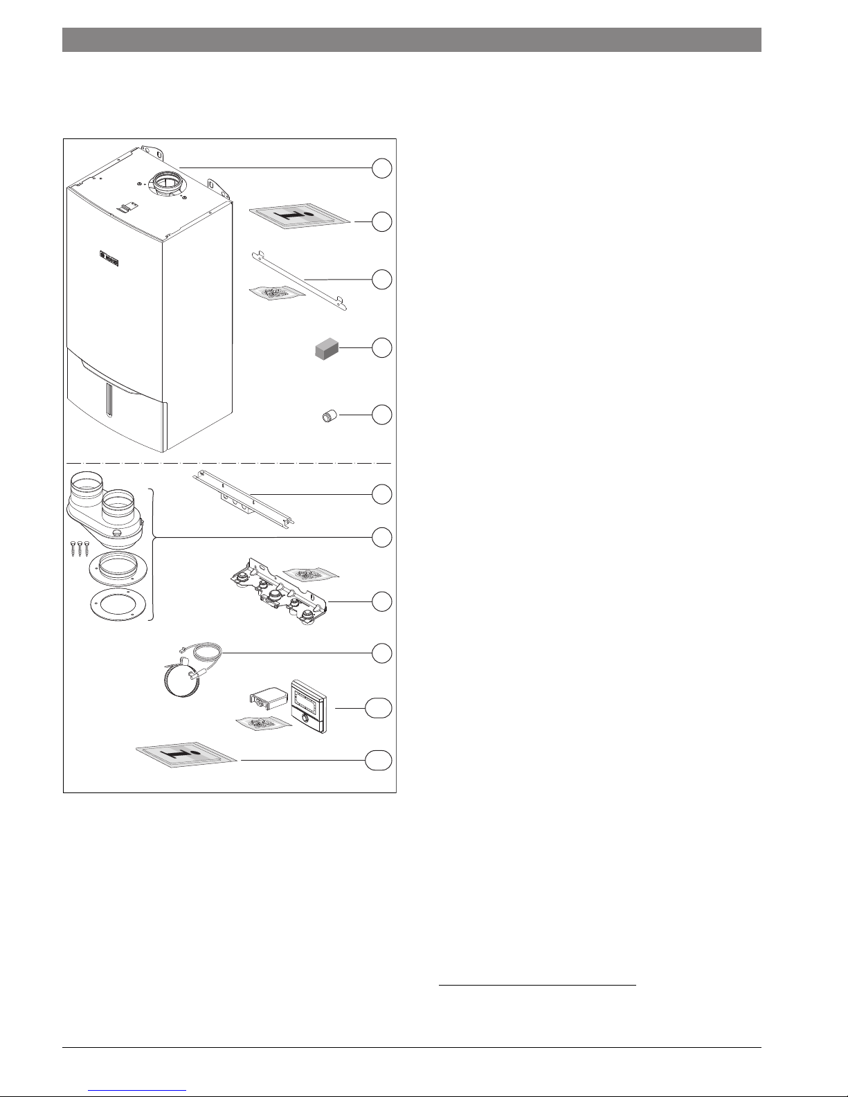
6 | Scope of delivery
2.2 ZWB - Residential combi boiler for space heating and
DHW generation
1
2
3
4
5
Contents of package 1:
[1] Gas condensing boiler
[2] Set of documents for appliance
[3] Mounting bracket with mounting kit
[4] Gas conversion kit
[5] Adapter for connection of a LWCO
Fig. 2 Scope of delivery combi boiler ZWB..-3A
6
7
8
9
10
11
6 720 641 933-04.2O
Contents of package 2:
[6] Rail with connection box
[7] Flue adapter
[8] Hydraulics connection plate with mounting kit
[9] External supply temperature sensor (NTC)
[10] Outdoor reset control FW 200 with mounting kit and outdoor
temperature sensor
[11] Set of documents for outdoor reset control FW 200
1)
1) Concentric vent kit available as accessory.
Greenstar6 720 806 992 (2015/03)
3 Information about the appliance
ZBR appliances are residential boilers for central heating and loading of
an indirect fired DHW tank.
ZWB appliances are residential combi boilers for central heating and on
demand DHW heating.
The appliances comply with South Coast Air Quality Management
District (SCAQMD) 2012 requirements: (Type-1) 14 Ng/J NO
20 ppm at 3% O
).
2
3.1 Proper use
The Greenstar boiler is not for use in CSD-1 commercial installation.
The appliance may only be installed in closed loop hot water central
heating systems.
Any other purpose is considered improper use. Any resulting damage is
excluded from the manufacturer's warranty.
The commercial and industrial use of the appliance for generating
process heat is not permitted.
3.2 Overview of boiler types
Table 2 describes the meaning of the model number:
(and/or
x
Information about the appliance | 7
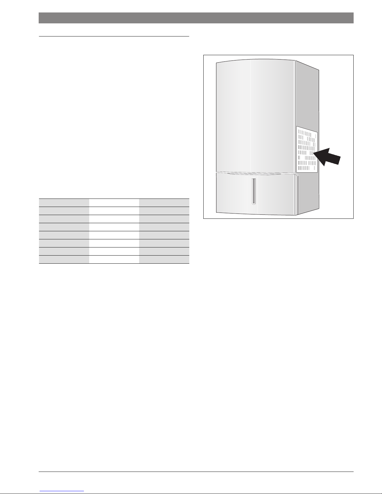
3.3 Rating plate
The rating plate is located at the right side of the appliance.
ZBR16-3 A 23
ZBR21-3 A 23
ZBR28-3 A 23
ZBR35-3 A 23
ZBR42-3 A 23
ZWB28-3 A 23
ZWB35-3 A 23
ZWB42-3 A 23
Table 2 Appliance types
Z Central heating appliance
W DHW heating
B Condensing technology
R Constant temperature control
16 Output up to 54,600 BTU/hr (16 kW)
21 Output and DHW output up to 71,600 BTU/hr (21 kW)
28 Output and DHW output up to 95,500 BTU/hr (28 kW)
35 Output and DHW output up to 119,400 BTU/hr (35 kW)
42 Output and DHW output up to 143,300 BTU/hr (42 kW)
-3 Version
A Fan-supported appliance
23 Natural gas (NG)
6 720 641 933-84.2O
Fig. 3 Position of the rating plate
The rating plate contains the appliance output, model number, approval
data and serial number.
3.4 Appliance description
• Appliance for wall installation, regardless of chimney and room size
• Outdoor reset control FW 200
• Intelligent boiler pump control
• Heatronic boiler control with 2-wire BUS
• Three-speed boiler circulator
• Automatic air vent (combi boiler ZWB..-3A only)
• Display
• Automatic ignition
• Continuously-controlled output
• Full protection via the Heatronic with flame rod and solenoid valves
• No minimum circulating water flow rate required
• Suitable for radiant floor heating
• Flue adapter for flue gas and combustion air with test ports
• Variable speed fan
• Gas premix burner
• Temperature sensor and temperature control for space heating
• Supply temperature sensor
• Temperature limiter
• Safety relief valve, pressure gauge
• Expansion vessel (combi boiler ZWB..-3A only)
• Connection possibility for DHW tank temperature sensor (NTC)
(heating boiler ZBR..-3A only)
• Flue gas temperature limiter
• DHW priority (combi boiler ZWB..-3A only)
• Motorized 3-way valve (combi boiler ZWB..-3A only)
• Hydraulics connection plate
6 720 806 992 (2015/03)Greenstar

8 | Information about the appliance
3.5 Accessories
Here you will find a list of typical accessories for this
appliance. Refer to the Bosch Product Catalog for a
complete overview of all available accessories.
• FB 100 room control
• Modules for system expansions:
– ISM2 for solar systems (DHW heating, space heating support, pool
heating)
– IPM2 for one or two heating zones with pump control and
motorized mixing capability
– ICM for cascading up to 4 boilers
– optional concentric vent kit available for horizontal direct vent
terminations
Greenstar6 720 806 992 (2015/03)
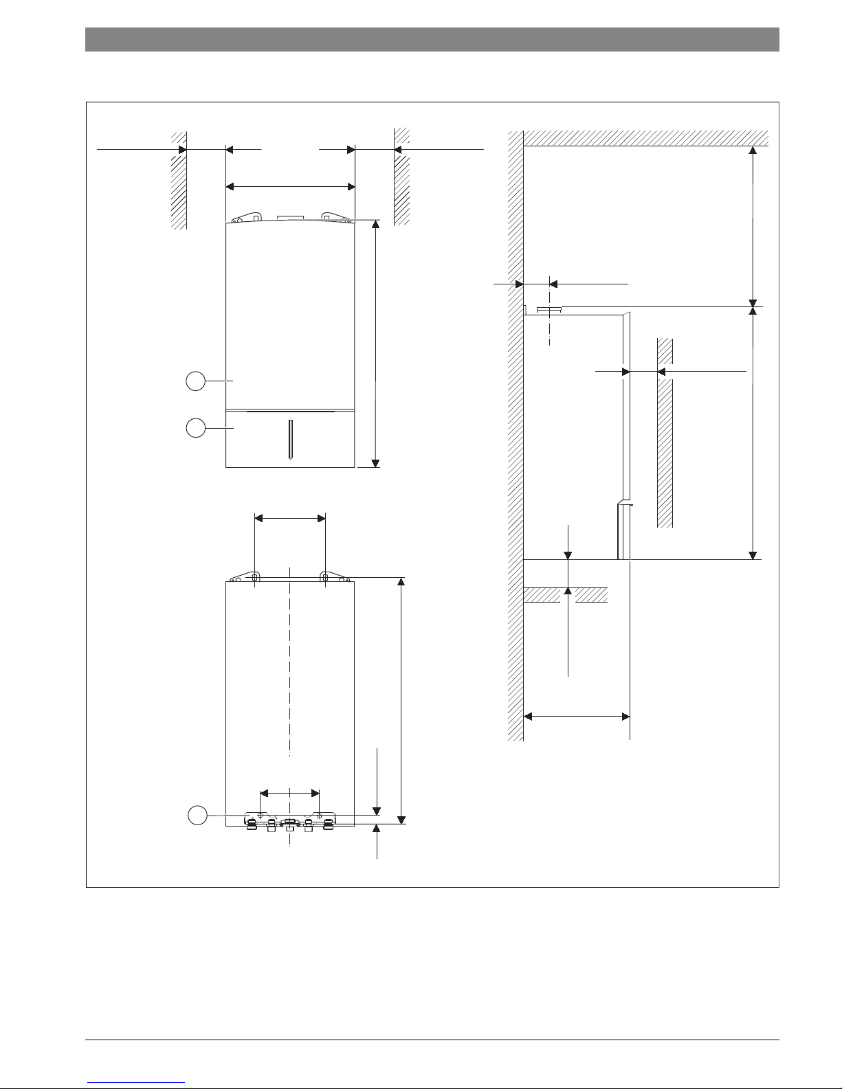
3.6 Product dimensions and minimum clearances
Information about the appliance | 9
≥ 4" *
(102 mm) *
≥ 4" *
(102 mm) *
17-21/64"
(440 mm)
≥ 15"
3-11/32"
(381 mm)
(85 mm)
(850 mm)
33-15/32"
1
≥ 4" **
(102 mm) **
2
(862 mm)
33-15/16"
9-29/64"
(240 mm)
(849 mm)
33-27/64"
7-7/8"
(200 mm)
1-3/16"
(30 mm)
3
Fig. 4 Dimensions and minimum clearances (front view, rear view, side view)
[1] Appliance jacket
[2] Service cover
[3] Hydraulics connection plate
(*) Zero clearance from combustibles permitted, but 4" (102 mm)
recommended for serviceability
(**) Distance to door, if mounted inside a closet
≥ 4" *
(102 mm) *
13-57/64"
(353 mm)
6 720 641 933-01.2O
6 720 806 992 (2015/03)Greenstar
10 | Information about the appliance
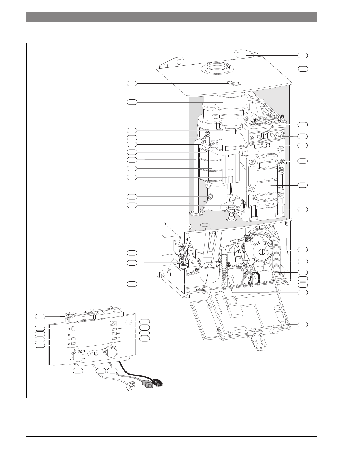
3.7 Appliance layout heating boiler ZBR..-3A
26
25
24
23
22
21
20
19
18
27
28
29
30
31
32
33
17
16
15
14
34
35
36
37
38
13
39
40
1
12
2
3
4
11
10
9
41
5
min
6
Fig. 5 Appliance layout heating boiler ZBR..-3A
8
7
6 720 641 933-02.2O
Greenstar6 720 806 992 (2015/03)

Key to Fig. 5:
[1] Heatronic boiler control
[2] ON/OFF switch
[3] Burner flame indicator
[4] Service button
[5] Emissions test button
[6] Boiler high limit dial
[7] Mounting socket for outdoor reset controls
[8] DHW thermostat
[9] Key pad lock
[10] ECO button
[11] Reset button
[12] Display
[13] Condensate trap
[14] Test ports for inlet gas pressure
[15] Adjustment screw, minimum gas volume
[16] Maximum gas adjuster
[17] Flue gas temperature limiter
[18] Combustion air intake
[19] Exhaust pipe
[20] Boiler supply pipe
[21] Connection for optional low water cut off (LWCO)
[22] Additional supply temperature limiter
[23] Manual air bleeder
[24] Gas/air premix chamber
[25] Fan
[26] Bracket
[27] Wall hanging bracket
[28] Exhaust pipe
[29] Sight glass
[30] Set of electrodes
[31] Supply temperature sensor
[32] Boiler block temperature limiter
[33] Inspection and cleanout cover
[34] Condensate collector
[35] Boiler circulator
[36] Pump speed switch
[37] Condensate drain hose
[38] Drain cock
[39] Pressure relief valve (heating zone)
[40] Safety relief valve discharge hose
[41] Boiler water pressure gauge
Information about the appliance | 11
6 720 806 992 (2015/03)Greenstar
12 | Information about the appliance
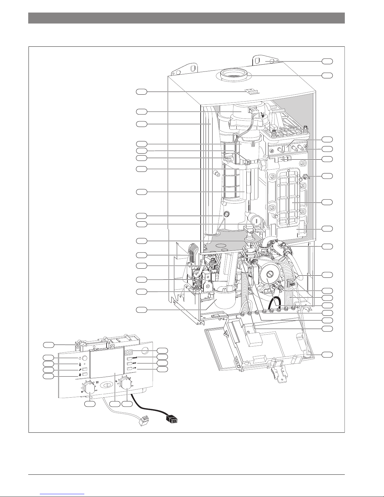
3.8 Appliance layout combi boiler ZWB..-3A
28
27
26
29
30
25
24
23
22
21
20
19
18
17
16
15
14
13
31
32
33
34
35
36
37
38
39
40
41
42
43
44
1
2
3
4
5
min
6
Fig. 6 Appliance layout combi boiler ZWB..-3A
8
7
12
11
10
9
45
6 720 641 933-03.2O
Greenstar6 720 806 992 (2015/03)

Key to Fig. 6:
[1] Heatronic boiler control
[2] ON/OFF switch
[3] Burner flame indicator
[4] Service button
[5] Emissions test button
[6] Boiler high limit dial
[7] Mounting socket for outdoor reset controls
[8] DHW thermostat
[9] Key pad lock
[10] ECO button
[11] Reset button
[12] Display
[13] Condensate trap
[14] Test ports for inlet gas pressure
[15] Adjustment screw, minimum gas volume
[16] DHW temperature sensor
[17] Plate-type heat exchanger
[18] Automatic air vent
[19] Maximum gas adjuster
[20] Flue gas temperature limiter
[21] Combustion air intake
[22] Supply pipe
[23] Connection for optional low water cut off (LWCO)
[24] Additional supply temperature limiter
[25] Gas/air premix chamber
[26] Expansion vessel
[27] Fan
[28] Bracket
[29] Wall hanging bracket
[30] Exhaust pipe
[31] Sight glass
[32] Set of electrodes
[33] Supply temperature sensor
[34] Boiler block temperature limiter
[35] Inspection and cleanout cover
[36] Condensate collector
[37] Flow meter
[38] 3-way valve
[39] Drain cock
[40] Condensate drain hose
[41] Boiler circulator
[42] Pump speed switch
[43] Pressure relief valve (heating zone)
[44] Safety relief valve discharge hose
[45] Boiler water pressure gauge
Information about the appliance | 13
6 720 806 992 (2015/03)Greenstar
14 | Information about the appliance
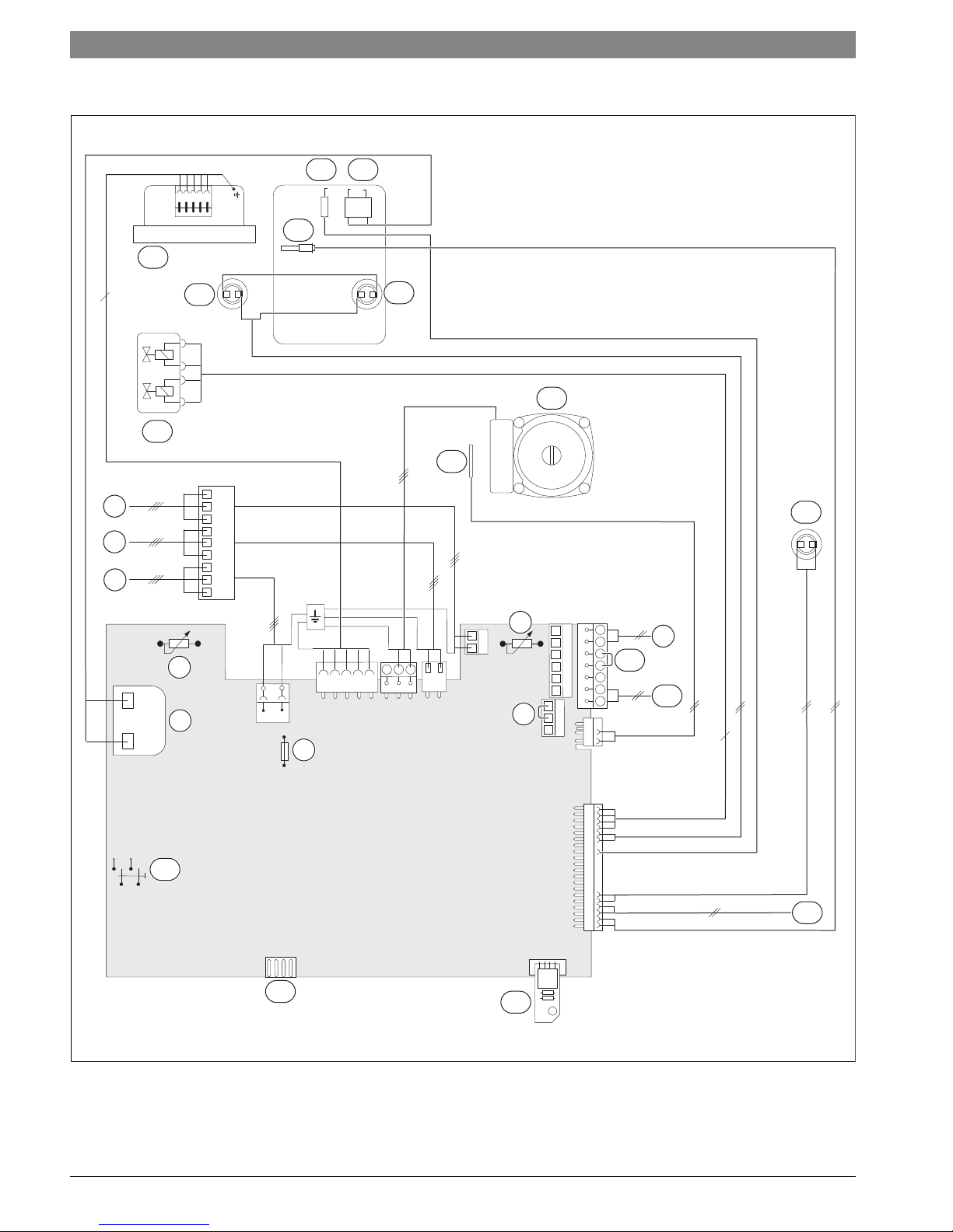
3.9 Electrical wiring heating boiler ZBR..-3A
19
18
16
20
6
17
21
23
15
22
9
5
4
3
8
7
6
5
4
23
1
7
NZ
LZ
2
L
N
LS NS
L
1
N
8
B
B
4
2
F
9
A
8
7
9
10
11
4
24
6
14
13
Fig. 7 Electrical wiring diagram heating boiler ZBR..-3A
12
25
6 720 641 933-23.3O
Greenstar6 720 806 992 (2015/03)

Key to Fig. 7:
[1] Ignition transformer
[2] Boiler high limit dial
[3] 120 VAC connection
[4] DHW tank primary pump or 3-way valve
[5] External heating pump for unmixed heating circuit (secondary
circuit)
2)
or DHW recirculation pump
1)
2)
[6] Fuse T 6.3 A (120 VAC)
[7] DHW thermostat
[8] External safety high limit or low water cut off (LWCO)
[9] BUS connection, e.g. heating control
[10] Room thermostat – dry contact
[11] Outdoor temperature sensor
[12] Code plug
[13] Diagnostic interface
[14] ON/OFF switch
[15] Gas valve
[16] Fan
[17] Flue gas temperature limiter
[18] Supply temperature sensor
[19] Flame rod electrode
[20] Ignition electrode
[21] Boiler block temperature limiter
[22] DHW tank temperature sensor (NTC)
[23] Boiler circulator
[24] Additional supply temperature limiter
[25] External system supply temperature sensor
Information about the appliance | 15
1) Set the service function 1.F, page 59
2) Set the service function 5.E, page 62
6 720 806 992 (2015/03)Greenstar
16 | Information about the appliance
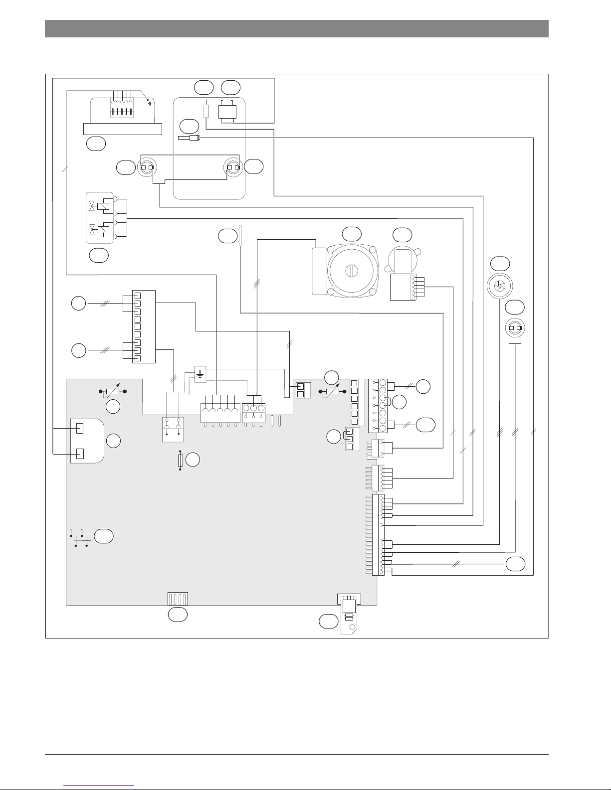
3.10 Electrical wiring combi boiler ZWB..-3A
18
17
15
19
6
16
21
20
22
23
14
24
9
4
3
2
1
8
7
6
5
4
23
1
25
6
NZ
LZ
LS NS
L
N
7
B
B
4
2
F
9
A
8
7
8
9
10
6
4
5
13
12
Fig. 8 Electrical wiring diagram combi boiler ZWB..-3A
11
26
6 720 641 933-24.3O
Greenstar6 720 806 992 (2015/03)

Key to Fig. 8:
[1] Ignition transformer
[2] Boiler high limit dial
[3] 120 VAC connection
[4] External heating pump for unmixed heating circuit (secondary
circuit)
1)
or DHW recirculation pump
1)
[5] Fuse T 6.3 A (120 VAC)
[6] DHW thermostat
[7] External safety high limit or low water cut off (LWCO)
[8] BUS connection, e.g. heating control
[9] Room thermostat – dry contact
[10] Outdoor temperature sensor
[11] Code plug
[12] Diagnostic interface
[13] ON/OFF switch
[14] Gas valve
[15] Fan
[16] Flue gas temperature limiter
[17] Supply temperature sensor
[18] Flame rod electrode
[19] Ignition electrode
[20] Boiler block temperature limiter
[21] DHW temperature sensor
[22] Boiler circulator
[23] 3-way valve (Space heating/DHW heating)
[24] Flow meter (turbine)
[25] Additional supply temperature limiter
[26] External system supply temperature sensor
Information about the appliance | 17
1) Set the service function 5.E, page 62
6 720 806 992 (2015/03)Greenstar

18 | Information about the appliance
3.11 Technical data heating boiler ZBR16-3A...
Input/Output Unit NG LPG (propane)
Max. input rate 180/79 °F (82/26 °C) BTU/hr (kW) 57,200 (16.8) 56,400 (16.5)
Max. output rate 104/86 °F (40/30 °C) BTU/hr (kW) 54,900 (16.1) 55,300 (16.2)
Max. output rate 122/86 °F (50/30 °C) BTU/hr (kW) 54,300 (15.9) 54,600 (16.0)
Max. output rate 176/140 °F (80/60 °C) BTU/hr (kW) 50,800 (14.9) 51,200 (15.0)
Min. input rate 180/79 °F (82/26 °C) BTU/hr (kW) 12,900 (3.8) 21,500 (6.3)
Min. output rate 104/86 °F (40/30 °C) BTU/hr (kW) 12,600 (3.7) 21,500 (6.3)
Min. output rate 122/86 °F (50/30 °C) BTU/hr (kW) 12,600 (3.7) 21,500 (6.3)
Min. output rate 176/140 °F (80/60 °C) BTU/hr (kW) 11,300 (3.3) 19,400 (5.7)
Gas connection value
Natural Gas – Hs = 1,010 BTU/ft3 (37.3 MJ/m3)ft
Liquid Propane Gas – HD-S = 2,500 BTU/ft3 (93.1 MJ/m3) ft3/hr (m3/h) – 22 (0.6)
Permissible inlet gas pressure
NG in. W.C. (mbar) 3.5-10.5" (8.7-26.1) –
LPG (propane) in. W.C. (mbar) – 8-13" (19.9-32.3)
Flue gas
Flue gas mass flow at maximum/minimum nominal output gps 6.8/1.7 6.7/2.6
Flue gas temperature 176/140 °F (80/60 °C) at maximum/minimum nominal
heat input
Flue gas temperature 104/86 °F (40/30 °C) at maximum/minimum nominal
heat input
CO2 at max. nominal output % 9.4 11.0
CO2 at minimum nominal output % 8.6 10.4
Condensate
Max. condensate quantity (tR = 86 °F (30 °C)) gph (l/h) 0.32 (1.2) 0.32 (1.2)
pH level, approx. 4.8 4.8
General
Voltage VAC 120 120
Frequency Hz 60 60
Max. power consumption (central heating mode) W 205 205
Max. power consumption (Stand-by) W < 6 < 6
Sound pressure level
Max. supply temperature °F ( °C) 190 (88) 190 (88)
Max. permissible operating pressure (PMS) heating psi (bar) 30 (2.07) 30 (2.07)
Permissible ambient temperature °F ( °C) 32 - 122 (0 - 50) 32 - 122 (0 - 50)
Nominal water capacity (heating) Gal (L) 0.925 (3.5) 0.925 (3.5)
Weight (without packaging) lbs. (kg) 103.6 (47) 103.6 (47)
Dimensions, W x H x D inch
Table 3 Technical data heating boiler ZBR16-3A...
3
/hr (m3/h) 56 (1.6) –
°F ( °C) 136/133 (58/56) 136/133 (58/56)
°F ( °C) 99/88 (37/31) 99/88 (37/31)
dB(A)
33 33
17-21/64" × 33-15/32" × 13-57/64"
(mm)
(440 × 850 × 353)
Greenstar6 720 806 992 (2015/03)

Information about the appliance | 19
3.12 Technical data heating boiler ZBR21-3A...
Input/Output Unit NG LPG (propane)
Max. input rate 180/79 °F (82/26 °C) BTU/hr (kW) 79,200 (23.2) 77,500 (22.7)
Max. output rate 104/86 °F (40/30 °C) BTU/hr (kW) 74,700 (21.9) 74,700 (21.9)
Max. output rate 122/86 °F (50/30 °C) BTU/hr (kW) 74,000 (21.7) 74,000 (21.7)
Max. output rate 176/140 °F (80/60 °C) BTU/hr (kW) 70,300 (20.6) 70,300 (20.6)
Min. input rate 180/79 °F (82/26 °C) BTU/hr (kW) 24,600 (7.2) 40,100 (11.7)
Min. output rate 104/86 °F (40/30 °C) BTU/hr (kW) 23,900 (7.0) 39,900 (11.7)
Min. output rate 122/86 °F (50/30 °C) BTU/hr (kW) 23,900 (7.0) 39,600 (11.6)
Min. output rate 176/140 °F (80/60 °C) BTU/hr (kW) 21,800 (6.4) 36,200 (10.6)
Gas connection value
Natural Gas – Hs = 1,010 BTU/ft3 (37.3MJ/m3)ft
Liquid Propane Gas – HD-S = 2,500 BTU/ft3 (93.1MJ/m3) ft3/hr (m3/h) – 31 (0.9)
Permissible inlet gas pressure
NG in. W.C. (mbar) 3.5-10.5" (8.7-26.1) LPG (propane) in. W.C. (mbar) – 8-13" (19.9-32.3)
Flue gas
Flue gas mass flow at maximum/minimum nominal output gps 9.4/3.2 9.2/4.8
Flue gas temperature 176/140 °F (80/60 °C) at maximum/minimum nominal
heat input
Flue gas temperature 104/86 °F (40/30 °C) at maximum/minimum nominal
heat input
CO2 at max. nominal output % 9.4 11.0
CO2 at minimum nominal output % 8.6 10.4
Condensate
Max. condensate quantity (tR = 86 °F (30 °C)) gph (l/h) 0.5 (1.8) 0.5 (1.8)
pH level, approx. 4.8 4.8
General
Voltage VAC 120 120
Frequency Hz 60 60
Max. power consumption (central heating mode) W 205 205
Max. power consumption (Stand-by) W < 6 < 6
Sound pressure level
Max. supply temperature °F ( °C) 190 (88) 190 (88)
Max. permissible operating pressure (PMS) heating psi (bar) 30 (2.07) 30 (2.07)
Permissible ambient temperature °F ( °C) 32 - 122 (0 - 50) 32 - 122 (0 - 50)
Nominal water capacity (heating) Gal (L) 0.925 (3.5) 0.925 (3.5)
Weight (without packaging) lbs. (kg) 103.6 (47) 103.6 (47)
Dimensions, W x H x D inch
Table 4 Technical data heating boiler ZBR21-3A...
3
/hr (m3/h) 78 (2.2) –
°F ( °C) 145/133 (63/56) 145/133 (63/56)
°F ( °C) 115/90 (46/32) 115/90 (46/32)
dB(A)
39 39
17-21/64" × 33-15/32" × 13-57/64"
(mm)
(440 × 850 × 353)
6 720 806 992 (2015/03)Greenstar

20 | Information about the appliance
3.13 Technical data heating boiler ZBR28-3A...
Input/Output Unit NG LPG (propane)
Max. input rate 180/79 °F (82/26 °C) BTU/hr (kW) 100,800 (29.5) 98,600 (28.9)
Max. output rate 104/86 °F (40/30 °C) BTU/hr (kW) 93,800 (27.5) 93,800 (27.5)
Max. output rate 122/86 °F (50/30 °C) BTU/hr (kW) 93,100 (27.3) 93,100 (27.3)
Max. output rate 176/140 °F (80/60 °C) BTU/hr (kW) 89,400 (26.2) 89,400 (26.2)
Min. input rate 180/79 °F (82/26 °C) BTU/hr (kW) 24,600 (7.2) 40,100 (11.7)
Min. output rate 104/86 °F (40/30 °C) BTU/hr (kW) 23,900 (7.0) 39,900 (11.7)
Min. output rate 122/86 °F (50/30 °C) BTU/hr (kW) 23,900 (7.0) 39,600 (11.6)
Min. output rate 176/140 °F (80/60 °C) BTU/hr (kW) 21,800 (6.4) 36,200 (10.6)
Gas connection value
Natural Gas – Hs = 1,010 BTU/ft3 (37.3MJ/m3)ft
Liquid Propane Gas – HD-S = 2,500 BTU/ft3 (93.1MJ/m3) ft3/hr (m3/h) – 39 (1.1)
Permissible inlet gas pressure
NG in. W.C. (mbar) 3.5-10.5" (8.7-26.1) LPG (propane) in. W.C. (mbar) – 8-13" (19.9-32.3)
Flue gas
Flue gas mass flow at maximum/minimum nominal output gps 12.0/3.2 11.6/4.8
Flue gas temperature 176/140 °F (80/60 °C) at maximum/minimum nominal
heat input
Flue gas temperature 104/86 °F (40/30 °C) at maximum/minimum nominal
heat input
CO2 at max. nominal output % 9.4 11.0
CO2 at minimum nominal output % 8.6 10.4
Condensate
Max. condensate quantity (tR = 86 °F (30 °C)) gph (l/h) 0.6 (2.3) 0.6 (2.3)
pH level, approx. 4.8 4.8
General
Voltage VAC 120 120
Frequency Hz 60 60
Max. power consumption (central heating mode) W 205 205
Max. power consumption (Stand-by) W < 6 < 6
Sound pressure level
Max. supply temperature °F ( °C) 190 (88) 190 (88)
Max. permissible operating pressure (PMS) heating psi (bar) 30 (2.07) 30 (2.07)
Permissible ambient temperature °F ( °C) 32 - 122 (0 - 50) 32 - 122 (0 - 50)
Nominal water capacity (heating) Gal (L) 0.925 (3.5) 0.925 (3.5)
Weight (without packaging) lbs. (kg) 103.6 (47) 103.6 (47)
Dimensions, W x H x D inch
Table 5 Technical data heating boiler ZBR28-3A...
3
/hr (m3/h) 99 (2.8) –
°F ( °C) 147/133 (64/56) 147/133 (64/56)
°F ( °C) 117/90 (47/32) 117/90 (47/32)
dB(A)
39 39
17-21/64" × 33-15/32" × 13-57/64"
(mm)
(440 × 850 × 353)
Greenstar6 720 806 992 (2015/03)

Information about the appliance | 21
3.14 Technical data heating boiler ZBR35-3A...
Input/Output Unit NG LPG (propane)
Max. input rate 180/79 °F (82/26 °C) BTU/hr (kW) 131,900 (38.6) 129,100 (37.8)
Max. output rate 104/86 °F (40/30 °C) BTU/hr (kW) 122,800 (36.0) 122,800 (36.0)
Max. output rate 122/86 °F (50/30 °C) BTU/hr (kW) 121,800 (35.7) 121,800 (35.7)
Max. output rate 176/140 °F (80/60 °C) BTU/hr (kW) 116,700 (34.2) 116,700 (34.2)
Min. input rate 180/79 °F (82/26 °C) BTU/hr (kW) 36,000 (10.5) 46,400 (13.6)
Min. output rate 104/86 °F (40/30 °C) BTU/hr (kW) 35,100 (10.3) 46,100 (13.5)
Min. output rate 122/86 °F (50/30 °C) BTU/hr (kW) 34,800 (10.2) 45,700 (13.4)
Min. output rate 176/140 °F (80/60 °C) BTU/hr (kW) 31,700 (9.3) 42,000 (12.3)
Gas connection value
Natural Gas – Hs = 1,010 BTU/ft3 (37.3MJ/m3)ft
Liquid Propane Gas – HD-S = 2,500 BTU/ft3 (93.1MJ/m3) ft3/hr (m3/h) – 52 (1.5)
Permissible inlet gas pressure
NG in. W.C. (mbar) 3.5-10.5" (8.7-26.1) –
LPG (propane) in. W.C. (mbar) – 8-13" (19.9-32.3)
Flue gas
Flue gas mass flow at maximum/minimum nominal output gps 15.7/4.5 15.2/5.6
Flue gas temperature 176/140 °F (80/60 °C) at maximum/minimum nominal
heat input
Flue gas temperature 104/86 °F (40/30 °C) at maximum/minimum nominal
heat input
CO2 at max. nominal output % 9.4 11.0
CO2 at minimum nominal output % 8.6 10.4
Condensate
Max. condensate quantity (tR = 86 °F (30 °C)) gph (l/h) 0.8 (3.1) 0.8 (3.1)
pH level, approx. 4.8 4.8
General
Voltage VAC 120 120
Frequency Hz 60 60
Max. power consumption (central heating mode) W 205 205
Max. power consumption (Stand-by) W < 6 < 6
Sound pressure level
Max. supply temperature °F ( °C) 190 (88) 190 (88)
Max. permissible operating pressure (PMS) heating psi (bar) 30 (2.07) 30 (2.07)
Permissible ambient temperature °F ( °C) 32 - 122 (0 - 50) 32 - 122 (0 - 50)
Nominal water capacity (heating) Gal (L) 0.925 (3.5) 0.925 (3.5)
Weight (without packaging) lbs. (kg) 103.6 (47) 103.6 (47)
Dimensions, W x H x D inch
Table 6 Technical data heating boiler ZBR35-3A...
3
/hr (m3/h) 130 (3.7) –
°F ( °C) 162/135 (72/57) 162/135 (72/57)
°F ( °C) 127/91 (53/33) 127/91 (53/33)
dB(A)
44 44
17-21/64" × 33-15/32" × 13-57/64"
(mm)
(440 × 850 × 353)
6 720 806 992 (2015/03)Greenstar

22 | Information about the appliance
3.15 Technical data heating boiler ZBR42-3A...
Input/Output at elevation 0 - 2000 feet (0 - 610 m) Unit NG LPG (propane)
Max. input rate 180/79 °F (82/26 °C) BTU/hr (kW) 151,600 (44.4) 148,300 (43.5)
Max. output rate 104/86 °F (40/30 °C) BTU/hr (kW) 137,500 (40.3) 137,500 (40.3)
Max. output rate 122/86 °F (50/30 °C) BTU/hr (kW) 137,500 (40.3) 137,500 (40.3)
Max. output rate 176/140 °F (80/60 °C) BTU/hr (kW) 134,400 (39.4) 134,400 (39.4)
Min. input rate 180/79 °F (82/26 °C) BTU/hr (kW) 36,000 (10.5) 46,400 (13.6)
Min. output rate 104/86 °F (40/30 °C) BTU/hr (kW) 35,500 (10.4) 46,400 (13.6)
Min. output rate 122/86 °F (50/30 °C) BTU/hr (kW) 35,100 (10.3) 46,100 (13.5)
Min. output rate 176/140 °F (80/60 °C) BTU/hr (kW) 31,700 (9.3) 42,000 (12.3)
Input/Output at elevation 2000 - 4500 feet (611 - 1372 m) above sea level
Max. input rate 180/79 °F (82/26 °C) BTU/hr (kW) 136,440 (40.0) 139,402 (40.9)
Max. output rate 104/86 °F (40/30 °C) BTU/hr (kW) 123,750 (36.3) 129,250 (37.9)
Max. output rate 122/86 °F (50/30 °C) BTU/hr (kW) 123,750 (36.3) 129,250 (37.9)
Max. output rate 176/140 °F (80/60 °C) BTU/hr (kW) 120,960 (35.5) 126,336 (37.0)
Input/Output at elevation 4500 - 7000 feet (1373 - 2134 m) above sea level
Max. input rate 180/79 °F (82/26 °C) BTU/hr (kW) 125,828 (36.9) 129,021 (37.8)
Max. output rate 104/86 °F (40/30 °C) BTU/hr (kW) 114,125 (33.5) 119,625 (35.1)
Max. output rate 122/86 °F (50/30 °C) BTU/hr (kW) 114,125 (33.5) 119,625 (35.1)
Max. output rate 176/140 °F (80/60 °C) BTU/hr (kW) 111,552 (32.7) 116,928 (34.3)
Gas connection value
Natural Gas – Hs = 1,010 BTU/ft3 (37.3MJ/m3)ft
Liquid Propane Gas – HD-S = 2,500 BTU/ft3 (93.1MJ/m3) ft3/hr (m3/h) – 59 (1.7)
Permissible inlet gas pressure
NG in. W.C. (mbar) 3.5-10.5" (8.7-26.1) –
LPG (propane) in. W.C. (mbar) – 8-13" (19.9-32.3)
Flue gas
Flue gas mass flow at maximum/minimum nominal output gps 18.0/4.5 17.5/5.6
Flue gas temperature 176/140 °F (80/60 °C) at maximum/minimum nominal heat
input
Flue gas temperature 104/86 °F (40/30 °C) at maximum/minimum nominal heat
input
CO2 at max. nominal output % 9.4 11.0
CO2 at minimum nominal output % 8.6 10.4
Condensate
Max. condensate quantity (tR = 86 °F (30 °C)) gph (l/h) 0.9 (3.5) 0.9 (3.5)
pH level, approx. 4.8 4.8
General
Voltage VAC 120 120
Frequency Hz 60 60
Max. power consumption (central heating mode) W 205 205
Max. power consumption (Stand-by) W < 6 < 6
Sound pressure level
Max. supply temperature °F ( °C) 190 (88) 190 (88)
Max. permissible operating pressure (PMS) heating psi (bar) 30 (2.07) 30 (2.07)
Permissible ambient temperature °F ( °C) 32 - 122 (0 - 50) 32 - 122 (0 - 50)
Nominal water capacity (heating) Gal (L) 0.925 (3.5) 0.925 (3.5)
Weight (without packaging) lbs. (kg) 103.6 (47) 103.6 (47)
Dimensions, W x H x D inch
Table 7 Technical data heating boiler ZBR42-3A...
3
/hr (m3/h) 149 (4.2) –
°F ( °C) 171/135 (77/57) 171/135 (77/57)
°F ( °C) 133/91 (56/33) 133/91 (56/33)
dB(A)
45 45
17-21/64" × 33-15/32" × 13-57/64"
(mm)
(440 × 850 × 353)
Greenstar6 720 806 992 (2015/03)

Information about the appliance | 23
3.16 Technical data combi boiler ZWB28-3A...
Input/Output Unit NG LPG (propane)
Max. input rate 180/79 °F (82/26 °C) BTU/hr (kW) 100,800 (29.5) 98,600 (28.9)
Max. output rate 104/86 °F (40/30 °C) BTU/hr (kW) 93,800 (27.5) 93,800 (27.5)
Max. output rate 122/86 °F (50/30 °C) BTU/hr (kW) 93,100 (27.3) 93,100 (27.3)
Max. output rate 176/140 °F (80/60 °C) BTU/hr (kW) 89,400 (26.2) 89,400 (26.2)
Output rate domestic hot water (DHW), 113 °F (45 °C) BTU/hr (kW) 93,600 (27.4) 93,600 (27.4)
Output rate domestic hot water (DHW), 140 °F (60 °C) BTU/hr (kW) 91,400 (26.8) 91,400 (26.8)
Min. input rate 180/79 °F (82/26 °C) BTU/hr (kW) 24,600 (7.2) 40,100 (11.7)
Min. output rate 104/86 °F (40/30 °C) BTU/hr (kW) 23,900 (7.0) 39,900 (11.7)
Min. output rate 122/86 °F (50/30 °C) BTU/hr (kW) 23,900 (7.0) 39,600 (11.6)
Min. output rate 176/140 °F (80/60 °C) BTU/hr (kW) 21,800 (6.4) 36,200 (10.6)
Gas connection value
Natural Gas – Hs = 1,010 BTU/ft3 (37.3MJ/m3)ft
Liquid Propane Gas – HD-S = 2,500 BTU/ft3 (93.1MJ/m3) ft3/hr (m3/h) – 39 (1.1)
Permissible inlet gas pressure
NG in. W.C. (mbar) 3.5-10.5" (8.7-26.1) –
LPG (propane) in. W.C. (mbar) – 8-13" (19.9-32.3)
Expansion vessel
Pre-charge pressure psi (bar) 10.9 (0.75) 10.9 (0.75)
Total contents Gal (L) 3.17 (12) 3.17 (12)
DHW
Max. DHW flow rate gpm (l/min) 2.64 (10) 2.64 (10)
Nominal DHW flow rate (at 140 °F (60 °C) outlet temperature) gpm (l/min) 2.03 (7.7) 2.03 (7.7)
Outlet temperature °F ( °C) 104 - 140 (40 - 60) 104 - 140 (40 - 60)
Max. cold water inlet temperature °F ( °C) 140 (60) 140 (60)
Max. approved DHW pressure psi (bar) 150 (10.3) 150 (10.3)
Minimum water pressure psi (bar) 4.35 (0.3) 4.35 (0.3)
Flue gas
Flue gas mass flow at maximum/minimum nominal output gps 12.0/3.2 11.7/4.9
Flue gas temperature 176/140 °F (80/60 °C) at maximum/minimum nominal
heat input
Flue gas temperature 104/86 °F (40/30 °C) at maximum/minimum nominal
heat input
CO2 at max. nominal output % 9.4 11.0
CO2 at minimum nominal output % 8.6 10.4
Condensate
Max. condensate quantity (tR = 86 °F (30 °C)) gph (l/h) 0.6 (2.3) 0.6 (2.3)
pH level, approx. 4.8 4.8
General
Voltage VAC 120 120
Frequency Hz 60 60
Max. power consumption (central heating mode) W 205 205
Max. power consumption (Stand-by) W < 6 < 6
Sound pressure level dB(A) 39 39
Max. supply temperature °F ( °C) 190 (88) 190 (88)
Max. permissible operating pressure (PMS) heating psi (bar) 30 (2.07) 30 (2.07)
Permissible ambient temperature °F ( °C) 32 - 122 (0 - 50) 32 - 122 (0 - 50)
Nominal water capacity (heating) Gal (L) 0.925 (3.5) 0.925 (3.5)
Weight (without packaging) lbs. (kg) 110.2 (50) 110.2 (50)
Dimensions, W x H x D
Table 8 Technical data combi boiler ZWB28-3A...
3
/hr (m3/h) 99 (2.8) –
°F ( °C)
°F ( °C)
inch
(mm)
147/133 (64/56) 147/133 (64/56)
117/90 (47/32) 117/90 (47/32)
17-21/64" × 33-15/32" × 13-57/64"
(440 × 850 × 353)
6 720 806 992 (2015/03)Greenstar

24 | Information about the appliance
3.17 Technical data combi boiler ZWB35-3A...
Input/Output Unit NG LPG (propane)
Max. input rate 180/79 °F (82/26 °C) BTU/hr (kW) 131,900 (38.6) 129,100 (37.8)
Max. output rate 104/86 °F (40/30 °C) BTU/hr (kW) 122,800 (36.0) 122,800 (36.0)
Max. output rate 122/86 °F (50/30 °C) BTU/hr (kW) 121,800 (35.7) 121,800 (35.7)
Max. output rate 176/140 °F (80/60 °C) BTU/hr (kW) 116,700 (34.2) 116,700 (34.2)
Output rate domestic hot water (DHW), 113 °F (45 °C) BTU/hr (kW) 120,500 (35.3) 120,500 (35.3)
Output rate domestic hot water (DHW), 140 °F (60 °C) BTU/hr (kW) 118,700 (34.8) 118,700 (34.8)
Min. input rate 180/79 °F (82/26 °C) BTU/hr (kW) 36,000 (10.5) 46,400 (13.6)
Min. output rate 104/86 °F (40/30 °C) BTU/hr (kW) 35,100 (10.3) 46,100 (13.5)
Min. output rate 122/86 °F (50/30 °C) BTU/hr (kW) 34,800 (10.2) 45,700 (13.4)
Min. output rate 176/140 °F (80/60 °C) BTU/hr (kW) 31,700 (9.3) 42,000 (12.3)
Gas connection value
Natural Gas – Hs = 1,010 BTU/ft3 (37.3MJ/m3)ft
Liquid Propane Gas – H
= 2,500 BTU/ft3 (93.1MJ/m3)ft
D-S
Permissible inlet gas pressure
NG in. W.C. (mbar) 3.5-10.5" (8.7-26.1) –
LPG (propane) in. W.C. (mbar) – 8-13" (19.9-32.3)
Expansion vessel
Pre-charge pressure psi (bar) 10.9 (0.75) 10.9 (0.75)
Total contents Gal (L) 3.17 (12) 3.17 (12)
DHW
Max. DHW flow rate gpm (l/min)
Nominal DHW flow rate (at 140 °F (60 °C) outlet temperature) gpm (l/min) 2.6 (10) 2.6 (10)
Outlet temperature °F ( °C) 104 - 140 (40 - 60) 104 - 140 (40 - 60)
Max. cold water inlet temperature °F ( °C) 140 (60) 140 (60)
Max. approved DHW pressure psi (bar) 150 (10.3) 150 (10.3)
Minimum water pressure psi (bar) 4.35 (0.3) 4.35 (0.3)
Flue gas
Flue gas mass flow at maximum/minimum nominal output gps 15.7/4.5 15.2/5.6
Flue gas temperature 176/140 °F (80/60 °C) at maximum/minimum nominal
heat input
Flue gas temperature 104/86 °F (40/30 °C) at maximum/minimum nominal
heat input
CO2 at max. nominal output % 9.4 11.0
CO2 at minimum nominal output % 8.6 10.4
Condensate
Max. condensate quantity (tR = 86 °F (30 °C)) gph (l/h) 0.8 (3.1) 0.8 (3.1)
pH level, approx. – 4.8 4.8
General
Voltage VAC 120 120
Frequency Hz 60 60
Max. power consumption (central heating mode) W 205 205
Max. power consumption (Stand-by) W < 6 < 6
Sound pressure level dB(A) 44 44
Max. supply temperature °F ( °C) 190 (88) 190 (88)
Max. permissible operating pressure (PMS) heating psi (bar) 30 (2.07) 30 (2.07)
Permissible ambient temperature °F ( °C) 32 - 122 (0 - 50) 32 - 122 (0 - 50)
Nominal water capacity (heating) Gal (L) 0.925 (3.5) 0.925 (3.5)
Weight (without packaging) lbs. (kg) 110.2 (50) 110.2 (50)
Dimensions, W x H x D
Table 9 Technical data combi boiler ZWB35-3A...
3
/hr (m3/h)
3
/hr (m3/h)
°F ( °C)
°F ( °C)
inch
(mm)
130 (3.7) –
– 52 (1.5)
3.17 (12) 3.17 (12)
162/135 (72/57) 162/135 (72/57)
127/91 (53/33) 127/91 (53/33)
17-21/64" × 33-15/32" × 13-57/64"
(440 × 850 × 353)
Greenstar6 720 806 992 (2015/03)

Information about the appliance | 25
3.18 Technical data combi boiler ZWB42-3A...
Input/Output at elevation 0 - 2000 feet (0 - 610 m) Unit NG LPG (propane)
Max. input rate 180/79 °F (82/26 °C)
Max. output rate 104/86 °F (40/30 °C)
Max. output rate 122/86 °F (50/30 °C)
Max. output rate 176/140 °F (80/60 °C)
Output rate domestic hot water (DHW), 113 °F (45 °C)
Output rate domestic hot water (DHW), 140 °F (60 °C)
Min. input rate 180/79 °F (82/26 °C)
Min. output rate 104/86 °F (40/30 °C)
Min. output rate 122/86 °F (50/30 °C)
Min. output rate 176/140 °F (80/60 °C)
BTU/hr (kW)
BTU/hr (kW)
BTU/hr (kW)
BTU/hr (kW)
BTU/hr (kW)
BTU/hr (kW)
BTU/hr (kW)
BTU/hr (kW)
BTU/hr (kW)
BTU/hr (kW)
Input/Output at elevation 2000 - 4500 feet (611 - 1372 m) above sea level
Max. input rate 180/79 °F (82/26 °C)
Max. output rate 104/86 °F (40/30 °C)
Max. output rate 122/86 °F (50/30 °C)
Max. output rate 176/140 °F (80/60 °C)
Output rate domestic hot water (DHW), 113 °F (45 °C)
Output rate domestic hot water (DHW), 140 °F (60 °C)
BTU/hr (kW)
BTU/hr (kW)
BTU/hr (kW)
BTU/hr (kW)
BTU/hr (kW)
BTU/hr (kW)
Input/Output at elevation 4500 - 7000 feet (1373 - 2134 m) above sea level
Max. input rate 180/79 °F (82/26 °C)
Max. output rate 104/86 °F (40/30 °C)
Max. output rate 122/86 °F (50/30 °C)
Max. output rate 176/140 °F (80/60 °C)
Output rate domestic hot water (DHW), 113 °F (45 °C)
Output rate domestic hot water (DHW), 140 °F (60 °C)
BTU/hr (kW)
BTU/hr (kW)
BTU/hr (kW)
BTU/hr (kW)
BTU/hr (kW)
BTU/hr (kW)
Gas connection value
Natural Gas – Hs = 1,010 BTU/ft3 (37.3MJ/m3)ft
Liquid Propane Gas – H
= 2,500 BTU/ft3 (93.1MJ/m3)ft
D-S
3
/hr (m3/h) 149 (4.2) –
3
/hr (m3/h) – 59 (1.7)
Permissible inlet gas pressure
NG in. W.C. (mbar) 3.5-10.5" (8.7-26.1) –
LPG (propane) in. W.C. (mbar) – 8-13" (19.9-32.3)
Expansion vessel
Pre-charge pressure psi (bar) 10.9 (0.75) 10.9 (0.75)
Total contents Gal (L) 3.17 (12) 3.17 (12)
DHW
Max. DHW flow rate gpm (l/min) 3.963 (15) 3.963 (15)
Nominal DHW flow rate (at 140 °F (60 °C) outlet temperature) gpm (l/min) 3.61 (11.4) 3.61 (11.4)
Outlet temperature °F ( °C) 104 - 140 (40 - 60) 104 - 140 (40 - 60)
Max. cold water inlet temperature °F ( °C) 140 (60) 140 (60)
Max. approved DHW pressure psi (bar) 150 (10.3) 150 (10.3)
Minimum water pressure psi (bar) 4.35 (0.3) 4.35 (0.3)
Flue gas
Flue gas mass flow at maximum/minimum nominal output gps 18.0/4.5 17.5/5.6
Flue gas temperature 176/140 °F (80/60 °C) at maximum/minimum nominal
°F ( °C) 171/135 (77/57) 171/135 (77/57)
heat input
Flue gas temperature 104/86 °F (40/30 °C) at maximum/minimum nominal
°F ( °C) 133/91 (56/33) 133/91 (56/33)
heat input
CO2 at max. nominal output % 9.4 11.0
CO2 at minimum nominal output % 8.6 10.4
Table 10 Technical data combi boiler ZWB42-3A...
151,600 (44.4) 148,300 (43.5)
137,500 (40.3) 137,500 (40.3)
137,500 (40.3) 137,500 (40.3)
134,400 (39.4) 134,400 (39.4)
137,500 (40.3) 137,500 (40.3)
135,800 (39.8) 135,800 (39.8)
36,000 (10.5) 46,400 (13.6)
35,500 (10.4) 46,400 (13.6)
35,100 (10.3) 46,100 (13.5)
31,700 (9.3) 42,000 (12.3)
136,440 (40.0) 139,402 (40.9)
123,750 (36.3) 129,250 (37.9)
123,750 (36.3) 129,250 (37.9)
120,960 (35.5) 126,336 (37.0)
123,750 (36.3) 129,250 (37.9)
122,220 (35.8) 127,652 (37.4)
125,828 (36.9) 129,021 (37.8)
114,125 (33.5) 119,625 (35.1)
114,125 (33.5) 119,625 (35.1)
111,552 (32.7) 116,928 (34.3)
114,125 (33.5) 119,625 (35.1)
112,714 (33.0) 118,146 (34.6)
6 720 806 992 (2015/03)Greenstar
26 | Regulations
Input/Output at elevation 0 - 2000 feet (0 - 610 m) Unit NG LPG (propane)
Condensate
Max. condensate quantity (tR = 86 °F (30 °C)) gph (l/h) 0.9 (3.5) 0.9 (3.5)
pH level, approx. – 4.8 4.8
General
Voltage VAC 120 120
Frequency Hz 60 60
Max. power consumption (central heating mode) W 205 205
Max. power consumption (Stand-by) W < 6 < 6
Sound pressure level
Max. supply temperature °F ( °C) 190 (88) 190 (88)
Max. permissible operating pressure (PMS) heating psi (bar) 30 (2.07) 30 (2.07)
Permissible ambient temperature °F ( °C) 32 - 122 (0 - 50) 32 - 122 (0 - 50)
Nominal water capacity (heating) Gal (L) 0.925 (3.5) 0.925 (3.5)
Weight (without packaging) lbs. (kg) 110.2 (50) 110.2 (50)
Dimensions, W x H x D inch
Table 10 Technical data combi boiler ZWB42-3A...
dB(A)
(mm)
45 45
17-21/64" × 33-15/32" × 13-57/64"
(440 × 850 × 353)
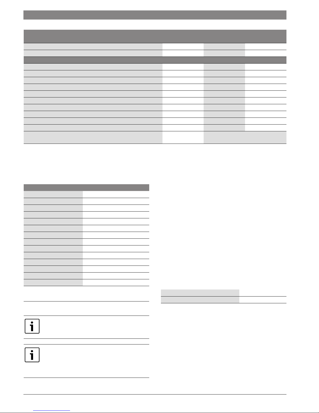
3.19 Condensate composition
The condensate volume and ingredients may change with regionally and
seasonally varying gas quality and air quality. Typically the following
ingredients and concentrations can be expected:
Substance Value in ppm (mg/l)
Ammonium 1.2
Lead 0.01
Cadmium 0.001
Chrome 0.005
Halogenated hydrocarbons 0.002
Hydrocarbons 0.015
Copper 0.028
Nickel 0.1
Mercury 0.0001
Sulfate 1
Zinc 0.015
Tin 0.01
Vanadium 0.001
pH-value 4.8
Table 11 Typical condensate composition
4 Regulations
Observe all rules, regulations, standards and guidelines
applicable to the installation and operation of this
appliance in your country.
In the Commonwealth of Massachusetts, this appliance
must be installed by a licensed plumber and gas fitter.
Valves external to the boiler must be fitted with
T-handles and condensate piping must be installed in
accordance with the State Plumbing Code.
4.1 Compliance with standards and regulations
The installation must conform to the requirements of the authority
having jurisdiction or, in the absence of such requirements, to the latest
edition of the National Fuel Gas Code, ANSI Z223.1./NFPA 54. In
Canada, installation must be in accordance with the requirements of
CAN/CSA B149.1, Natural Gas and Propane Installation Code.
This wall mounted condensing gas boiler complies in its design and
mode of operation with the American National Standard ANSI Z21.13/
CSA4.9, latest edition for Gas Fired Low Pressure Steam and Hot Water
Boilers.
Other confirmed approvals and certifications are indicated by labels on
the boiler.
Where required by the authority having jurisdiction, the installation must
conform to the Standard for Controls and Safety Devices for
Automatically Fired Boilers, ANSI/ASME CSD-1.
Install CO detectors per local regulations. Boiler requires yearly
maintenance ( chapter 15, page 68).
4.2 Operating limits of the boiler
The heat exchanger has been designed and certified in accordance with
the ASME Boiler and Pressure Vessel Code, Section IV.
Maximum boiler temperature 190 °F (88 °C)
Maximum operating pressure 30 psi (2.07 bar)
Table 12 Operating limits
The hot water distribution system must comply with all applicable codes
and regulations. When replacing an existing boiler, it is important to
check the condition of the entire hot water distribution system to ensure
safe operation. Common practice calls for inspecting an existing system
in its entirety and bringing it up to code. All pipework should be properly
cleaned and flushed.
Greenstar6 720 806 992 (2015/03)

Regulations | 27
4.3 Additional regulations for installation in
Massachusetts
(a) For all side wall horizontally vented gas fueled equipment installed in
every dwelling, building or structure used in whole or in part for
residential purposes, including those owned or operated by the
Commonwealth and where the side wall exhaust vent termination is less
than seven (7) feet [2150 mm] above finished grade in the area of the
venting, including but not limited to decks and porches, the following
requirements shall be satisfied:
• INSTALLATION OF CARBON MONOXIDE DETECTORS. At the time of
installation of the side wall horizontal vented gas fueled equipment,
the installing plumber or gasfitter shall observe that a hard wired
carbon monoxide detector with an alarm and battery back-up is
installed on the floor level where the gas equipment is to be installed.
In addition, the installing plumber or gasfitter shall observe that a
battery operated or hard wired carbon monoxide detector with an
alarm is installed on each additional level of the dwelling, building or
structure served by the side wall horizontal vented gas fueled
equipment. It shall be the responsibility of the property owner to
secure the services of qualified licensed professionals for the
installation of hard wired carbon monoxide detectors.
– In the event that the side wall horizontally vented gas fueled
equipment is installed in a crawl space or an attic, the hard wired
carbon monoxide detector with alarm and battery back-up may be
installed on the next adjacent floor level.
– In the event that the requirements of this subdivision can not be
met at the time of completion of installation, the owner shall have a
period of thirty (30) days to comply with the above requirements;
provided, however, that during said thirty (30) day period, a
battery operated carbon monoxide detector with an alarm shall be
installed.
• APPROVED CARBON MONOXIDE DETECTORS. Each carbon
monoxide detector as required in accordance with the above
provisions shall comply with NPA 720 and be ANSI/UL 2034 listed
and IAS certified.
• SIGNAGE. A metal or plastic identification plate shall be permanently
mounted to the exterior of the building at a minimum height of eight
(8) feet above grade directly in line with the exhaust vent terminal for
the horizontally vented gas fueled heating appliance or equipment.
The sign shall read, in print size no less than one-half (½) inch in size,
“GAS VENT DIRECTLY BELOW. KEEP CLEAR OF ALL
OBSTRUCTIONS”.
• INSPECTION. The state or local gas inspector of the side wall
horizontally vented gas fueled equipment shall not approve the
installation unless, upon inspections, the inspector observes carbon
monoxide detectors and signage installed in accordance with the
provisions of 248 CRM 5.08(2)(a) 1 through 4.
(b) EXEMPTIONS: The following equipment is exempt from 248 CRM
5.08(2)(a) 1 through 4:
• The equipment listed in Chapter 10 entitled “Equipment Not Required
To Be Vented” in the most current edition of NFPA 54 as adopted by
the board; and
• Product Approved side wall horizontally vented gas fueled equipment
installed in a room or structure separate from the dwelling, building or
structure used in whole or in part for residential purposes.
(c) MANUFACTURERS REQUIREMENTS - GAS EQUIPMENT VENTING
SYSTEM REQUIRED. When the manufacturer of Product Approved side
wall horizontally mounted gas equipment provides a venting system
design or venting system components with the equipment, the
instructions provided by the manufacturer for the installation of the
equipment and venting shall include:
• Detailed instructions for the installation of the venting system or the
venting system components; and
• A complete parts list for the venting system design or venting system.
(d) MANUFACTURERS REQUIREMENTS - GAS EQUIPMENT VENTING
SYSTEM NOT PROVIDED. When the manufacturer of Product Approved
side wall horizontally vented gas fueled equipment does not provide the
parts for the venting of flue gases, but identifies special venting systems,
the following requirements shall be satisfied by the manufacturer:
• The referenced special venting systems shall be included with the
appliance or equipment installation instructions; and
• The special venting systems shall be Product Approved by the Board,
and the instructions for that system shall include a parts list and
detailed installation instructions.
(e) A copy of all instructions for all Product Approved side wall
horizontally vented gas fueled equipment, all venting instructions, all
parts lists for venting instructions, and/or venting design instructions
shall remain with the appliance or equipment at the completion of the
installation.
6 720 806 992 (2015/03)Greenstar
28 | Common Applications of ZBR boilers
5 Common Applications of ZBR boilers
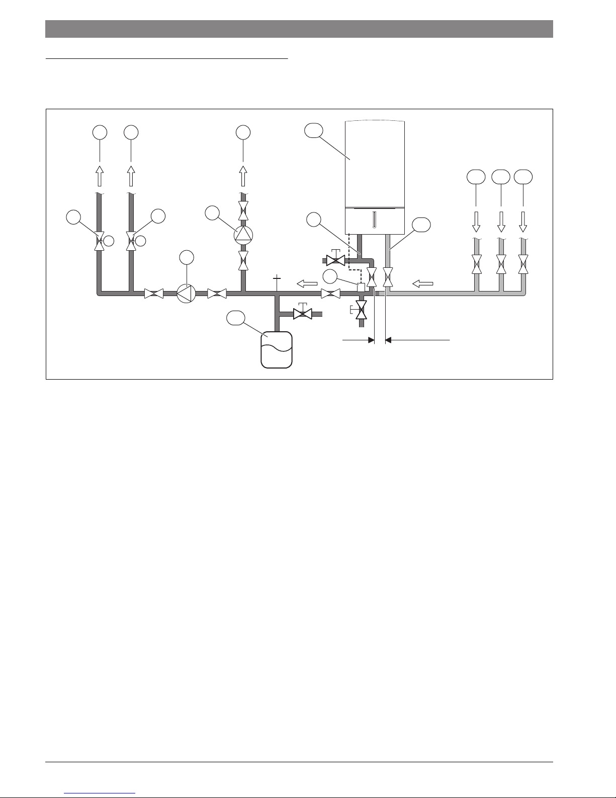
5.1 Multiple zones using zone valves with DHW
1
2
3
4
MM
6
7
5
15
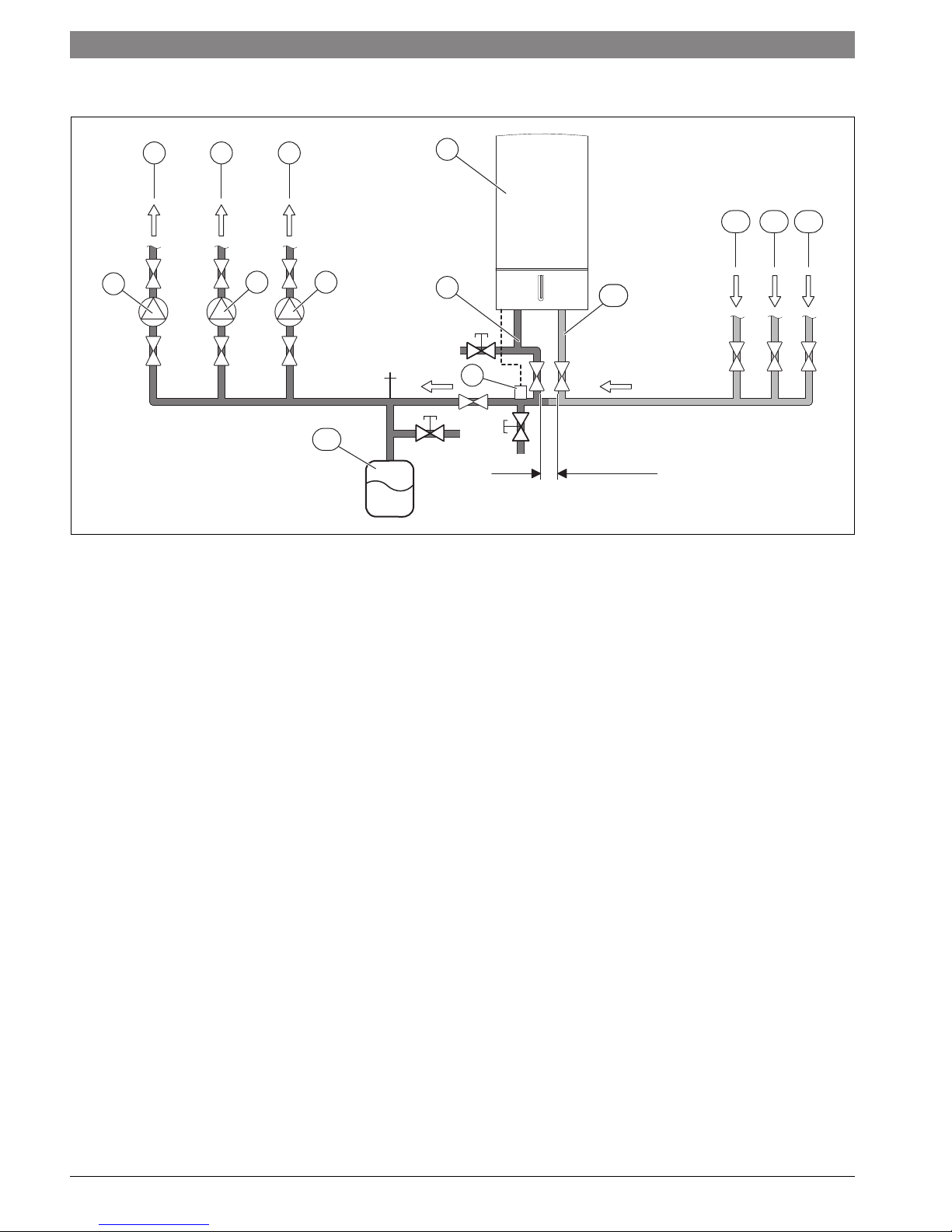
Fig. 9 Piping
[1] To heating zone 2
[2] Motorized valve heating zone 2
[3] To heating zone 1
[4] Motorized valve heating zone 1
[5] System pump
[6] DHW pump
[7] To indirect tank
[8] External system supply temperature sensor for system supply
pipe (to be installed in closest vicinity with boiler supply Tee)
[9] Boiler primary line - supply pipe 1"
[10] Heating boiler ZBR..-3A... with FW 200 installed on front
[11] Boiler primary line - return pipe 1"
[12] From indirect tank
[13] From heating zone 1
[14] From heating zone 2
[15] Expansion vessel
X 4 × pipe diameters on boiler primery side (here 4 × 1")
10
9
1312 14
11
8
ϑ
X
6 720 806 992-03.1O
Greenstar6 720 806 992 (2015/03)
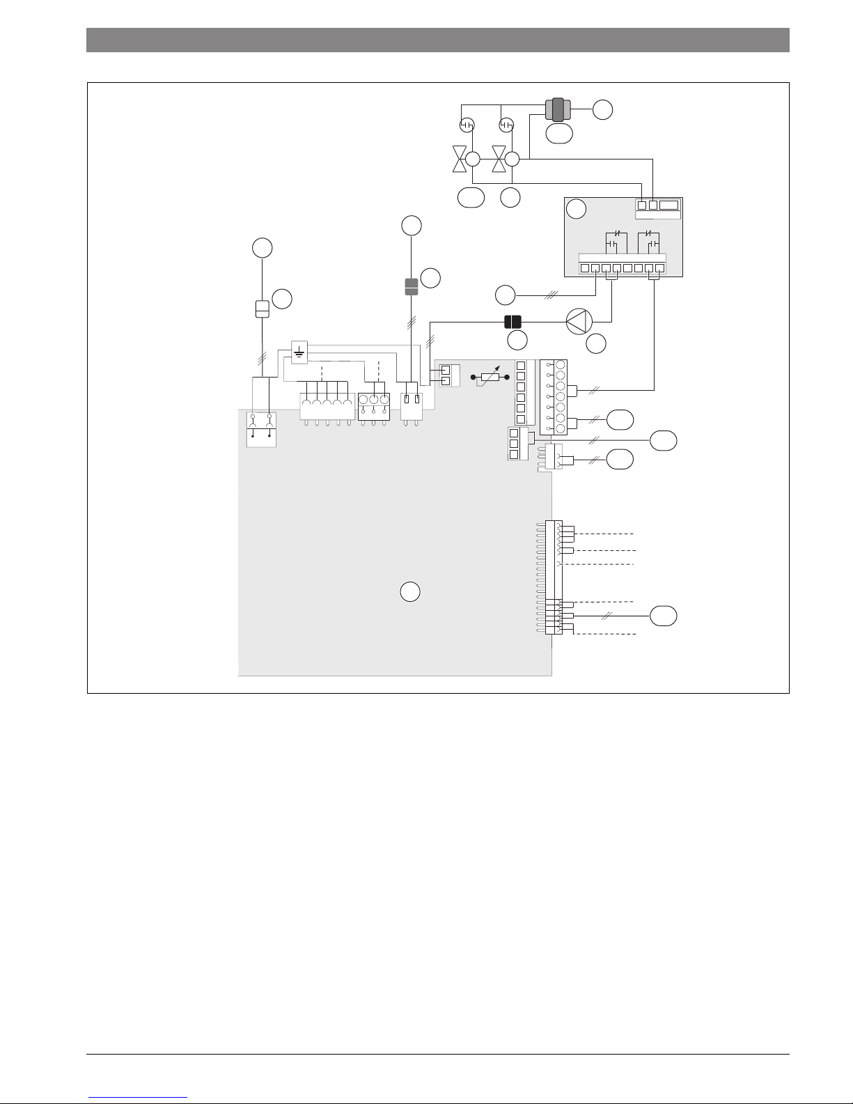
Common Applications of ZBR boilers | 29
3
11
MM
10
9
8
24VAC
RW
T T COM
5
3
NH344556
4
2
NZ
LZ
L
N
LS NS
L
N
3
6
B
B
4
2
F
9
A
8
7
7
12
13
14
1
F
V
15
Fig. 10 Wiring
[1] PCB in heating boiler ZBR..-3A... with FW 200 installed on front
[2] White plug for mains power supply, 120 V AC, 60 Hz
( chapter 7.3.4, page 49)
[3] 120 V AC, 60 Hz
[4] Red plug for external DHW tank ( chapter 7.3.3, page 49)
[5] DHW pump
[6] Black plug for extermnal (system) pump ( chapter 7.3.2,
page 48)
[7] System pump
[8] DPDT Relay
[9] Motorized valve heating zone 2
[10] Motorized valve heating zone 1
[11] 24 V AC transformer
[12] Outdoor temperature sensor
[13] LWCO (Low Water Cut Off, 24V AC Transformer required)
[14] DHW temperature sensor (connection with clear connector)
[15] External supply temperature sensor (connection with white plug)
6 720 806 992-04.1O
6 720 806 992 (2015/03)Greenstar
30 | Common Applications of ZBR boilers
5.2 Multiple zones using circulators with DHW
1
3
2
5
4 6
14
Fig. 11 Piping
[1] To heating zone 2
[2] Pump heating zone 2
[3] To heating zone 1
[4] Pump heating zone 1
[5] To indirect tank
[6] DHW pump
[7] External system supply temperature sensor for system
supplypipe (to be installed in closest vicinity with
boiler supply Tee)
[8] Boiler primary line - supply pipe 1"
[9] Heating boiler ZBR..-3A... with FW 200 installed on front
[10] Boiler primary line - return pipe 1"
[11] From indirect tank
[12] From heating zone 1
[13] From heating zone 2
[14] Expansion vessel
X 4 × pipe diameters on boiler primery side (here 4 × 1")
9
1211 13
8
11
10
7
ϑ
X
6 720 806 992-05.1O
Greenstar6 720 806 992 (2015/03)
 Loading...