

Page 1

Operating Instructions
GAS WATER HEATER
Owner’s Guide
Models YS2180RA YS2180RA5 YS2180RAP YS2180RA5P
YS1780RA YS1780RA5 YS1780RAP YS1780RA5P
WARNING
If the information in this manual is not followed exactly, a fire or explosion
may result causing property damage, personal injury, or death.
- Do not store or use petrol or other flammable vapours and liquids in the
vicinity of this or any other appliance.
- WHAT TO DO IF YOU SMELL GAS
• Do not try to light the appliance.
• Do not touch any electrical switches; Do not use electrical appilances,
including
the phone” inside the building.
• Immediately call you gas supplier, from a safe distance from the gas leak.
- To be installed and serviced only by an authorised person
- This appliance is not suitable for use as a pool heater
Thank you for purchasing this Bosch Gas Water Heater.
Before using, please:
Read this manual completely for operation instructions.
Confirm warranty and proof of purchase.
Keep this manual where it can be found whenever necessary.
Installation must conform with local codes, or in the absence of local codes, AS/NZS5601, AS/
NZS3500.4, AS3000 wiring regulations and all Local Building, Water and Gas fitting regulations.
Bosch
reserves the right to discontinue, or change at any time, the designs and/or specifications of
its products without notice.
* Note : This appliance requires a minimum flow rate to operate of 2.5 litres/min., water fixtures with a
flow rate of 7.5 litres/min. or higher are recommended.
For optimum performance we reommend installation of Bosch optional temperature controllers.
Robert Bosch (Australia) Pty. Ltd.
SBB80BU
Rev. 04/14
*SBB80BU*
Page 2

Operating Instructions
Important Safety Information
To prevent damage to property and injury to the user, the icons shown below will be used to warn of
varying levels of danger.
Every indication is critical to the safe operation of the water heater and must be understood and observed.
Potential dangers from accidents during installation and use are divided into the following four
categories. Closely observe these warnings; they are critical to your safety.
Icons warning of risk level
This is the safety alert symbol. It is used to alert you to potential personal injury hazards.
Obey all safety messages that follow this symbol to avoid possible injury or death.
DANGER indicates an imminently hazardous situation which,
DANGER
WARNING
if not avoided, will result in death or serious injury.
WARNING indicates a potentially hazardous situation which, if not
avoided, could result in death or serious injury.
CAUTION
CAUTION
Other icons
Electric
Shock.
Prohibited
Vapours from flammable liquids will explode and catch fire causing death or severe burns.
Prohibited
Do not use or store flammable products such as petrol, solvents or
adhesives in the same room or area near the water heater.
Keep flammable products:
1. Far away from the water
heater.
2. In approved containers.
3. Tightly closed.
4. Out of children’s reach.
CAUTION indicates a potentially hazardous situation which, if not
avoided, may result in minor or moderate injury.
CAUTION used without the safety alert symbol indicates a potentially
hazardous situation which, if not avoided, may result in property damage.
High
Temperature.
No flame.
Be sure
to do.
Don’t
touch.
Earth
Don’t
disassemble
the equipment.
Don’t touch
with a wet
hand.
DANGER
Vapours:
1. Cannot be seen.
2. Vapours are heavier than air.
3. Go a long way on the floor.
4. Can be carried from other rooms
to the main burner by air currents.
Vapours
Hot Water Heater temperatures over 50 °C can cause severe burns instantly or
death from scalding.
Prohibited
Children, disabled and elderly are at the highest risk of being scalded.
Feel water temperature before bathing or showering.
Temperature limiting valves are available, ask licensed installer.
2
(Continued)
Page 3

(Continued)
Operating Instructions
Do Not Install Indoors.
Prohibited
No flame.
This will cause carbon monoxide poisoning and a potential fire hazard.
WARNING
A. This water heater does not have a
pilot. It is equipped with an
ignition device that automatically
lights the burner. Do not try to
light the burner by hand.
B.
BEFORE OPERATING smell all
around the water heater area for
evidence of leaking gas. Be sure
to smell next to the floor because
some gas is heavier than air and
will settle on the floor.
WHAT TO DO IF YOU SMELL GAS.
• Do not try to light any
appliance.
• Do not touch any electrical
switch; do not use any phone
in your building.
•
Immediately call your gas
supplier.
Follow the gas supplier’s
instructions.
C. Use only your hand to turn the
gas valve knob. Never use tools.
If the knob will not turn by hand,
don’t try to repair it. Call a
qualified service technician.
Force or attempted repair may
result in a fire or explosion.
D. Do not use this water heater if
any part has been under water.
lmmediately call a qualified
service technician to inspect the
water heater and to replace any
damaged parts.
Be sure
Be sure
Temperature.
Be sure
When a gas leak is noticed:
1. Stop use immediately
2. Close the gas valve
to do.
3.
Contact your gas supplier immediately
If you detect abnormal combustion
or abnormal odours, or during an
earthquake, tornado or fire:
to do.
1. Turn off the hot water supply
2.
Turn off the power to the water heater
3.
Turn off gas and water supply valve.
4. Call the Bosch Helpline
AU 1300 30 70 37 NZ 0800 54 33 52.
Check the temperature
of the running hot water
before entering the
High
shower.
Check the temperature
before stepping into
the bath tub.
Leave the proper clearance between
the water heater and nearby objects
(trees, timber, boxes with flammable
to do.
materials etc.).
Left side:
Min. 500mm
Front:
Sug. 600mm
Indoor
Upper:
Min. 500mm
Right side:
Min. 500mm
(Continued)
3
Page 4

Operating Instructions
Important Safety Information
(Continued)
Prohibited
Do not place the unit in an indoor environment by means of adding walls
and ceiling (Do not enclose using
corrugated sheets, etc.)
Unit
Carbon monoxide poisoning or fire may
occur as a result.
Be sure
Be sure the gas matches
the gas on the data
(inside of frontcover)
to do.
gas type label (right side
of casing).
Ex. For Natural Gas (YS2180RA)
plate
or
Prohibited
Prohibited
Prohibited
Prohibited
Carbon Monoxide Poisoning
Hazard. Do not install this water
heater in a mobile home, recreation
vehicle or on a boat.
Do not place combustibles such as
laundry, newspapers, oils etc. near
the heater.
Unit
Do not use combustible chemicals
such as oil, petrol, benzene etc. in
the near the water heater or the
exhaust vent.
Do not store or use petrol or other
flammable vapours and liquids in the
vicinity of this or any other appliance.
Be sure
to do.
Prohibited
Prohibited
Don’t touch
with a wet
hand.
Be sure
to do.
Installation and service must be
performed by a qualified installer,
service agency or the gas supplier.
Do not use hair spray or spray
detergent in the vicinity of the
heater.
Do not allow small children to play
unsupervised in the bathroom.
Do not allow small children to
bathe unsupervised.
Do not touch the power
cord with wet hands.
Electric
Shock.
Contact Bosch before using with
a solar pre-heater.
Do not place or use a spray can
near the water heater or the exhaust
Prohibited
vent.
4
Don’t
disassemble
the equipment.
Contact a qualified service
technician for any necessary
repairs, service or maintenance.
Page 5

Operating Instructions
CAUTION
Earth
Be sure
to do.
Prohibited
Prohibited
Be sure
to do.
Be sure to electrically earth the
unit.
Keep power cord free of dust.
Do not use the water heater for
other than hot water supply, shower
and bath.
Do not use a broken or modified power
cord. Do not bind, bend or stretch
power cords. Do not scratch, modify,
or subject them to impact or force.
To prevent burns or scalding, turn
off the power button and wait until
the equipment cools before performing maintenance.
Prohibited
Prohibited
Prohibited
Don’t
touch.
Do not turn off the water heater
while someone is bathing.
Do not cover the water heater, store
trash or debris near it, or in any way
block the flow of fresh air to the unit.
Do not install in locations where
excessive dust or debris will be
in the air.
Do not touch the exhaust vent
during or immediately after
operation of the water heater.
5
Page 6

Operating Instructions
Important Safety Information
CAUTION
Do not drink water that has been inside the
unit for an extended period of time. Do not
drink the first use of hot water from the
unit in the morning.
Clean the filter on the water inlet as
frequently as required. The quality of your
local water will affect the frequency required.
Keep the area around the unit clean.
If boxes, weeds, cobwebs, cockroaches etc. are in
the vicinity of the unit, damage or fire can result.
Do not install the equipment where the
exhaust will blow on walls or windows.
Treat hard, acidic or otherwise impure
supply water with approved methods to
ensure full warranty coverage.
Problems resulting from scale formation
are not covered by the warranty.
Do not disassemble the remote controller.
Do not use benzene, oil or fat detergents
to clean the remote controller.
This may cause deformation.
Do not get the remote controller wet.
YPRS67XBN and YPRP62XBN are water resistant,
too much water can cause damage.
YPRM67XBN is not water resistant.
Do not splash water on the remote
controller. Do not expose the remote
controller to steam.
Do not locate the remote controller near stoves or
ovens, this may cause damage or failure.
Preventing damage from freezing ( p.22)
Damage can occur from frozen water within the
device and pipes even in warm environments.
Be sure to read below for appropriate measures.
Repairs for damage caused by freezing are not
covered by the warranty.
Do not run water through the unit when
unit is not on.
When discharging hot water, make sure the unit is ON.
If water is run through the unit with the unit
OFF, water may condense inside the unit and cause
incomplete combustion or damage to the internal
electrical components.
6
Power must be switched on at all times for
antifrost protection to work.
If it is snowing, check the air inlet, exhaust
gas vent and exhaust vent terminal for
blockage.
Do not use parts other than those specified
for this equipment.
Page 7

Contents
Important Safety Information....................................................................... 2
Contents ........................................................................................................ 7
General Parts
Main Unit.................................................................................................... 8
Names and Functions of Controllers
Main Controller (YPRM67XBN) ................................................................ 9
Bathroom Controller (YPRS67XBN) ....................................................... 10
Operating Instructions
Sub Controller (YPRP62XBN) ................................................................. 11
Initial Operation ........................................................................................... 12
Clock Adjustment ........................................................................................ 13
Setting and Using the Water Heater........................................................... 14
Controller Priority Function ........................................................................ 16
Muting the Remote Controller .................................................................... 17
Bath Fill Function ........................................................................................ 18
Call Function ................................................................................................ 21
Frost Protection ........................................................................................... 22
Regular Maintenance................................................................................... 23
Troubleshooting .......................................................................................... 25
Follow-up Service ........................................................................................ 29
Specifications .............................................................................................. 30
Manufacturer’s Warranty ............................................................................ 35
7
Page 8

Operating Instructions
General Parts
Main Unit
Outdoor Wall Mounted, Power flue Model
Flue Collar
Front Cover
Air Inlet
Water Drain Valve (with Water Filter)
(Inside Water Inlet) ( p.24)
Gas Supply Valve
Water Supply Valve
Hot Water Pipe
External Weatherproof Power Point
* The above illustration shows an example of installation.
The exact installation configuration may be slightly different.
8
Page 9

Operating Instructions
Names and Functions of Controllers
Main Controller (YPRM67XBN) <Optional>
What is actually displayed depends on how the water heater is set.
Setting Buttons
For setting the hot
water temperature
( p.14 -15)
For other settings.
Display
Time Set Button
To set or lndicate Time
of day. ( p.13)
Bath Fill Volume Button
For setting the amount
of water that is delivered.
( p.18 -20)
* Before use, remove the protective sheet from the remote controller surface.
Display
The illustration below shows the remote controller display.
What is actually displayed depends on how the water heater is set.
Burner On Indicator
When burning, the
indicator is lit.
( p.15, 19)
Operation Button
For turning the water
heater on or off.
Bath Fill Button
To activate Bath Fill.
To set Bath Fill
temperature.
( p.18 -20)
Bath Fill Temperature Indicator
When this indicator is lit,
bath fill temperature is
displayed. ( p.18 -20)
Priority Indicator
When this indicator is lit,
the hot water temperature
can be set. ( p.16)
Error Code
A number will flash if
a failure occurs.
( p.28)
Clock
When Time Set button
is pushed, the clock is
displayed. ( p.13)
Temperature setting
(Eg.: 40°C)
Bath Fill Temperature setting
(Eg.: 40°C)
Bath Fill Volume setting
( p.18 -21)
9
Page 10

Operating Instructions
Bathroom Controller (YPRS67XBN) <Optional>
What is actually displayed depends on how the water heater is set.
Setting Buttons
For setting the hot
water temperature
( p.14 -15)
For other settings.
Display
Call Button
To sound alarm at all
remote controls. ( p.21)
Priority Button
To transfer control from
another remote
( p.16)
* Before use, remove the protective sheet from the remote controller surface.
.
Display
The illustration below shows the remote controller display.
What is actually displayed depends on how the water heater is set.
Burner On Indicator
When burning, the
indicator is lit.
( p.15, 19)
Operation Button
For turning the water
heater on or off.
Bath Fill Button
To activate Bath Fill.
To set Bath Fill
temperature.
( p.18 -20)
Bath Fill Temperature Indicator
When this indicator is lit,
bath fill temperature is
displayed. ( p.18 -20)
Priority Indicator
When this indicator is lit,
the hot water temperature
can be set. ( p.16)
10
Error Code
A number will flash if
a failure occurs.
( p.28)
Temperature setting
(Eg.: 40°C)
Bath Fill Temperature setting
(Eg.: 40°C)
Bath Fill Volume setting
( p.18 -20)
Page 11

Operating Instructions
Sub Controller (YPRP62XBN) <Optional>
What is actually displayed depends on how the water heater is set.
Display
* Before use, remove the protective sheet from the remote controller surface.
Display
The illustration below shows the remote controller display.
What is actually displayed depends on how the water heater is set.
Operation Button
For turning the water
heater on or off.
Setting Buttons
For setting the hot
Water temperature.
( p.14 -15)
Priority Indicator
When this indicator is lit,
the hot water temperature
can be set. ( p.16)
Burner On Indicator
When burning, the
indicator is lit.
( p.15, 19)
Temperature setting
(Eg.: 40°C)
Error Code
A number will flash if
a failure occurs.
( p.28)
11
Page 12
Operating Instructions
Initial Operation
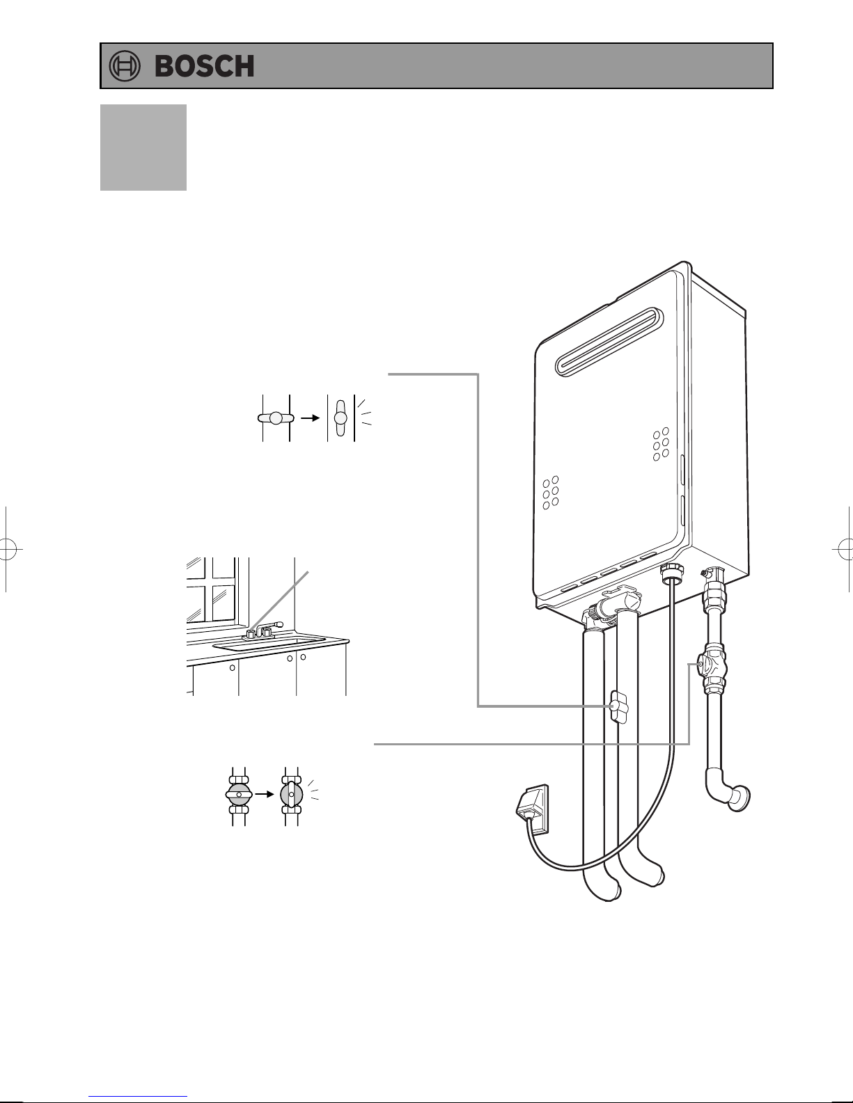
Before the first use of your water heater, make the following preparations.
Follow steps 1 through 4.
Open the water supply valve.
1
CLOSED
OPEN
Open a hot water fixture to confirm that
water is available, and then close the
2
fixture again.
Hot water fixture
Open the gas supply valve.
3
Turn on the power.
4
12
Page 13
Operating Instructions
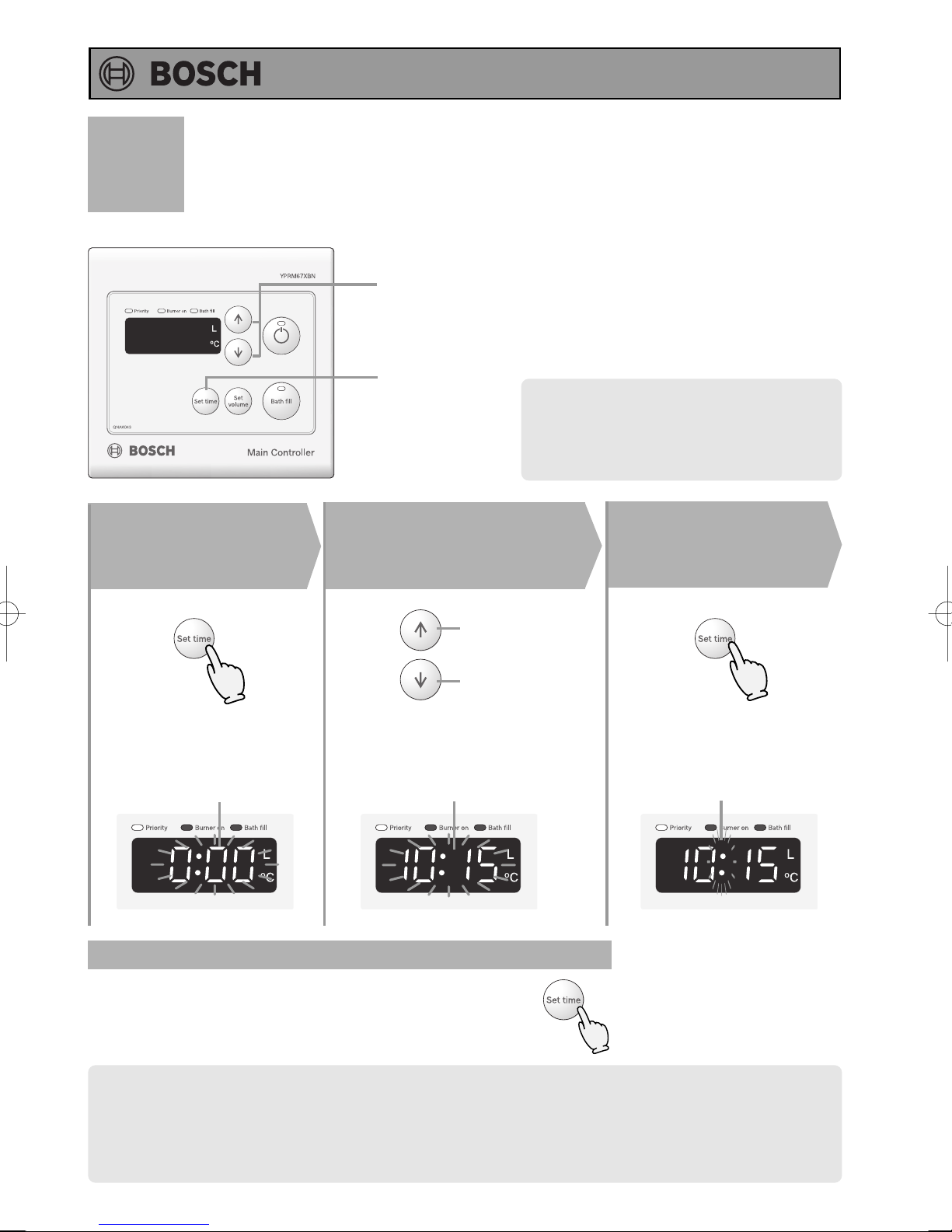
Clock Adjustment
(Main Controller)
2
Note: Only the main controller has a clock
function.
Press the Set
Time Button
1
(Until “0:00” is flashing)
Flashing
1, 3
Adjust the clock
Clock setting and the clock can be displayed regardless of “ON or OFF" of
the operation button.
(The illustration is in a state of "OFF".)
2
Increase
Decrease
The time changes in 1-minute increments
with each press on the button, and
then in 10-minute increments if the
button is kept pressed down.
Flashing
Press the Set
3
Time Button
The flashing changes to
constant illumination when the
clock has been set.
Flashing
Display the clock
Press the set time button.
The clock display will then return to the original screen display.
• The clock display will disappear if hot water is used or the temperature of the hot water is changed during
the clock display.
• If the Time set button is pushed when the hot water is being used or a high temperature (60°C) is set, the
clock is displayed for 10 seconds and will return to the original screen display after that.
• In the event of a power cut or after disconnecting the power supply, the clock on the display screen will
show 0:00 when the power is restored. In this case the clock will need to be reset.
(Eg.: 10:15)
13
Page 14
Operating Instructions
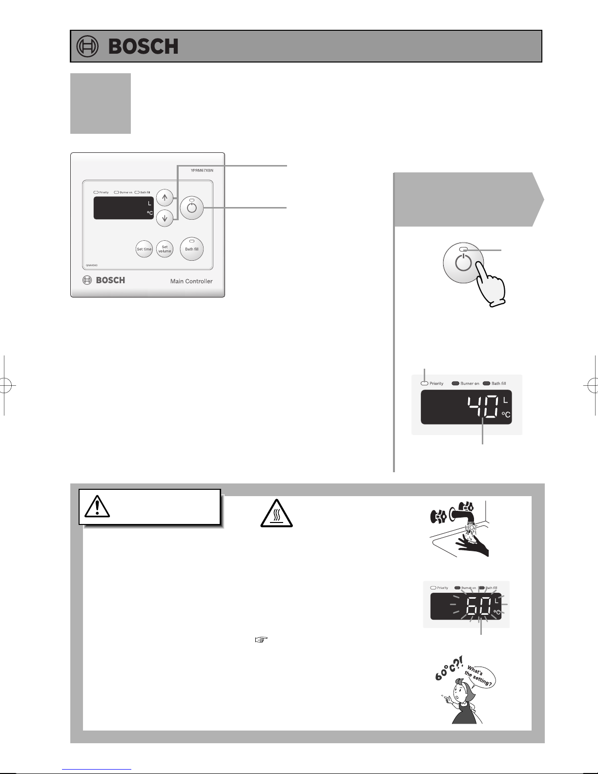
Setting and Using the Water Heater
(Main Controller)
2
1
(Starting with the Operation Off)
Press the Operation
Button.
1
On
The temperature will be
displayed on the remote
control thermostat.
On
DANGER
High Temperature
Hot Water Heater temperatures over 50°C can cause
severe burns instantly or death from scalding.
• Children, disabled and elderly are at the highest risk of being scalded.
Feel water temperature before bathing or showering.
Temperature limiting valves are available, ask licensed installer.
• When setting the unit to 60°C ( p.15), the temperature
display will flash for 10 seconds.
• Take caution when using the unit again after setting to 50°C
or higher. Always check the set temperature before use.
To prevent scalding:
Previous set temperature
(Eg.: 40°C)
Remote Controller Display
Flashes for 10 sec
14
Page 15
Operating Instructions
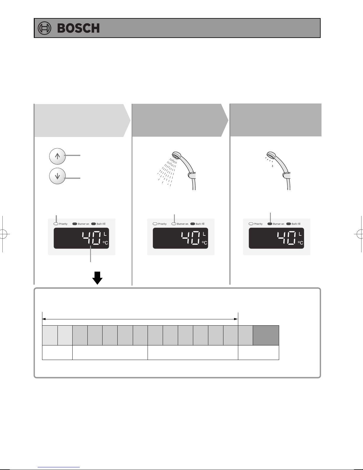
Set temperature.
2
Always check the
temperature setting
(
before use.
Hot
Cold
Check the indicator lights.
Water temperature
)
3
Turn on hot
water.
On
Turn off the hot
water.
4
Off
The temperature settings below are examples. The temperature setting
:
(°C
necessary depends on the usage, the length of piping or seasons.
Bathroom and Sub controller are these ranges.
[RA5: Main and Bathroom and Sub controller are these ranges.]
37 38 39 40 41 42 43 44 45 46 47 48 50 55 60
Shower, hot water supply, etc.
* For most residential applications, the recommended setting temperature is 50°C or less.
For applications that occasionally require a higher temperature setting, locate the remote controller
in a convenient location.
* Consult local codes for minimum operating temperatures.
)
Hot water supply, etc.
*Initial factory setting is 40°C
High temperature
15
Page 16
Operating Instructions
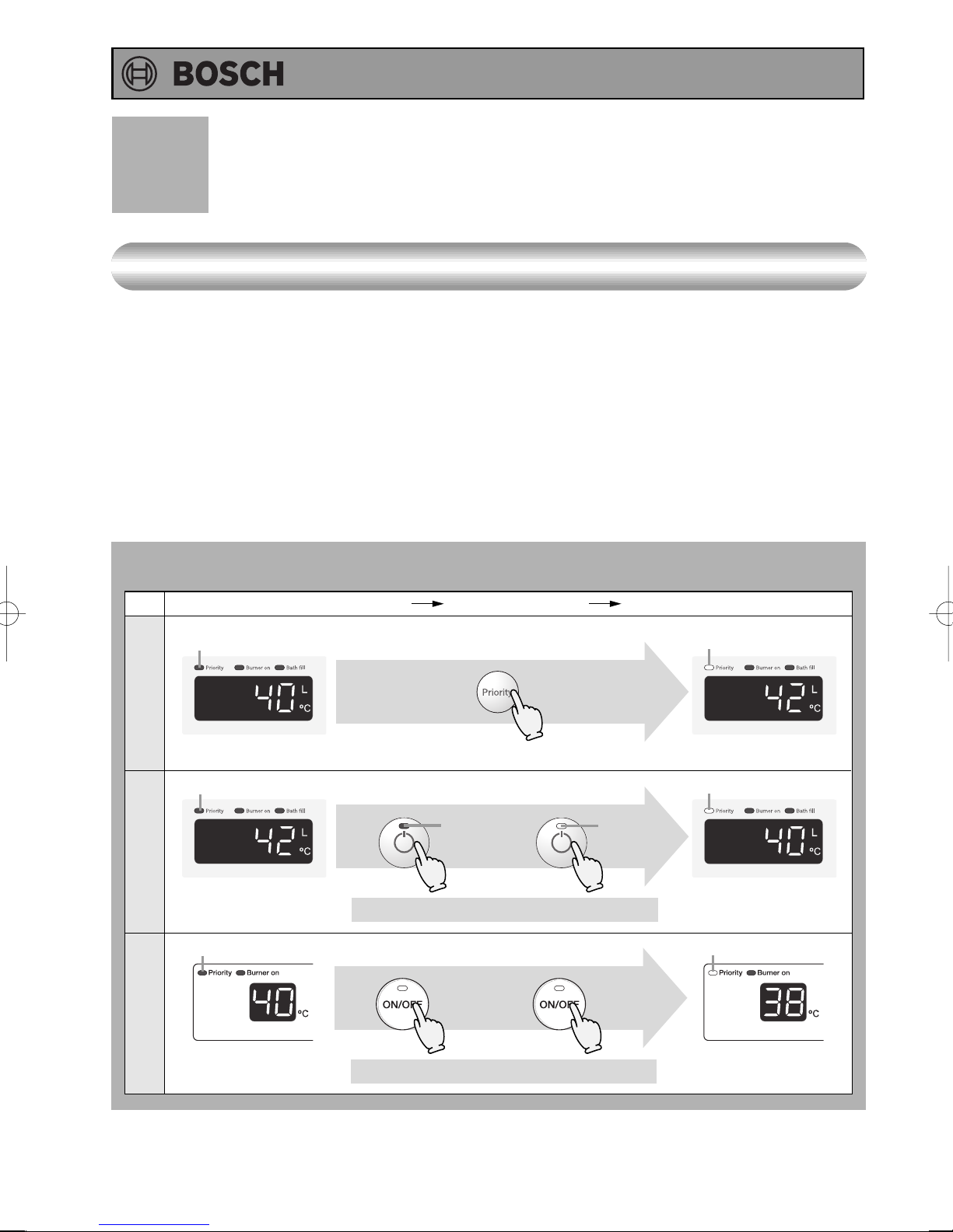
Controller Priority Function
Priority
Hot water supplied from this appliance is delivered to the kitchen, washroom, and shower, etc. at the
same temperature.
The water temperature can only be changed by one remote controller if a number of remote controllers
are installed.
Only the controller with the priority light illuminated will be able to adjust the temperature of the water
heater.
• The remote controller on which the operation button is turned “on” has priority.
• If the Bathroom or Sub controller has priority left ON, press OFF & ON any other controller to transfer
priority to that controller. This function cannot be changed while the appliance is producing hot water
(Except when hot water is operating).
When the temperature cannot be adjusted, follow the procedure below. <Priority button>
(Temperature settings for example.)
Temperature cannot be adjusted Switch priority Temperature can be adjusted
Bathroom Controller
Off
Main Controller
Sub Controller
Off
Off
Press the priority button
Turn off the
operation button.
Off
* Care must be taken as operation is interrupted.
Turn off the
operation button.
Turn on the operation
button once again.
On
Turn on the operation
button once again.
On
On
On
16
* Care must be taken as operation is interrupted.
Page 17
Operating Instructions
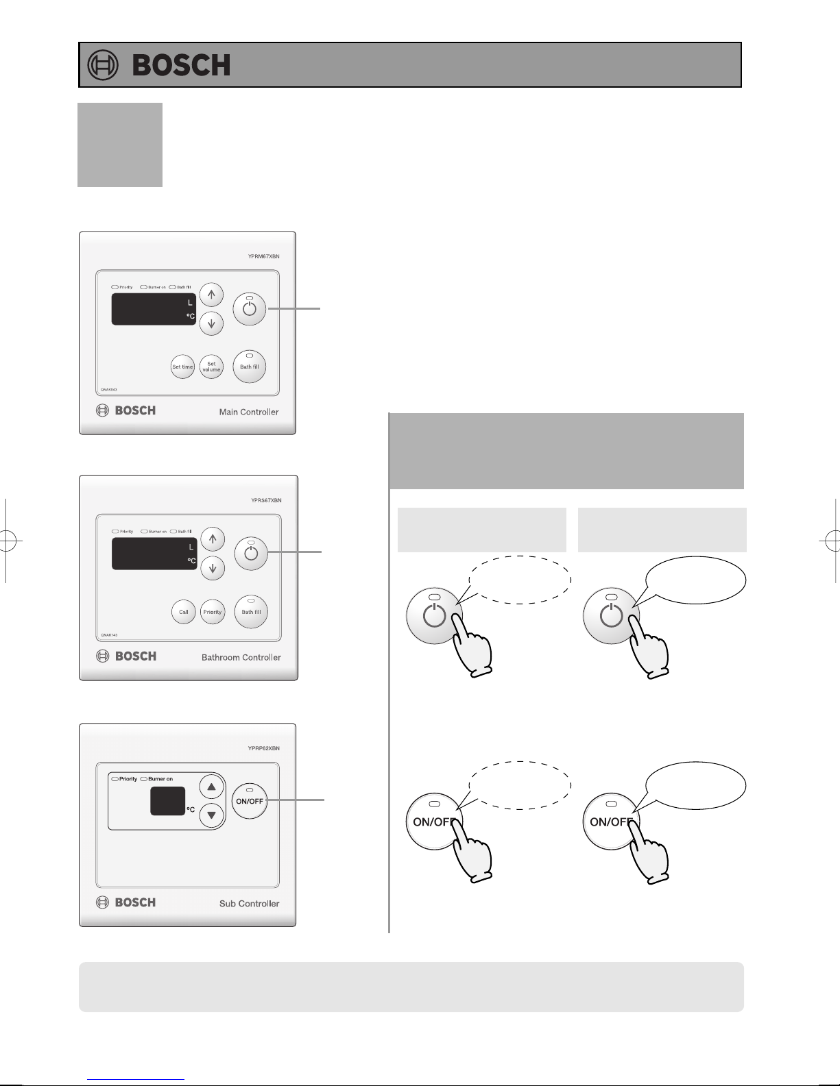
Muting the Remote Controller
(Main Controller)
(Bathroom Controller)
1
1
The remote controller will emit a sound
when any button is pushed. This sound
can be muted if it is desired.
* Initial factory setting is with sound
Hold the Operation Button
1
for five seconds.
Muted
No sound
after 5 sec.
Sound
Tone sounds
after 5 sec.
(Sub Controller)
• The bath fill and the call function alarm are not muted.
1
No sound
after 5 sec.
Tone sounds
after 5 sec.
17
Page 18
Operating Instructions
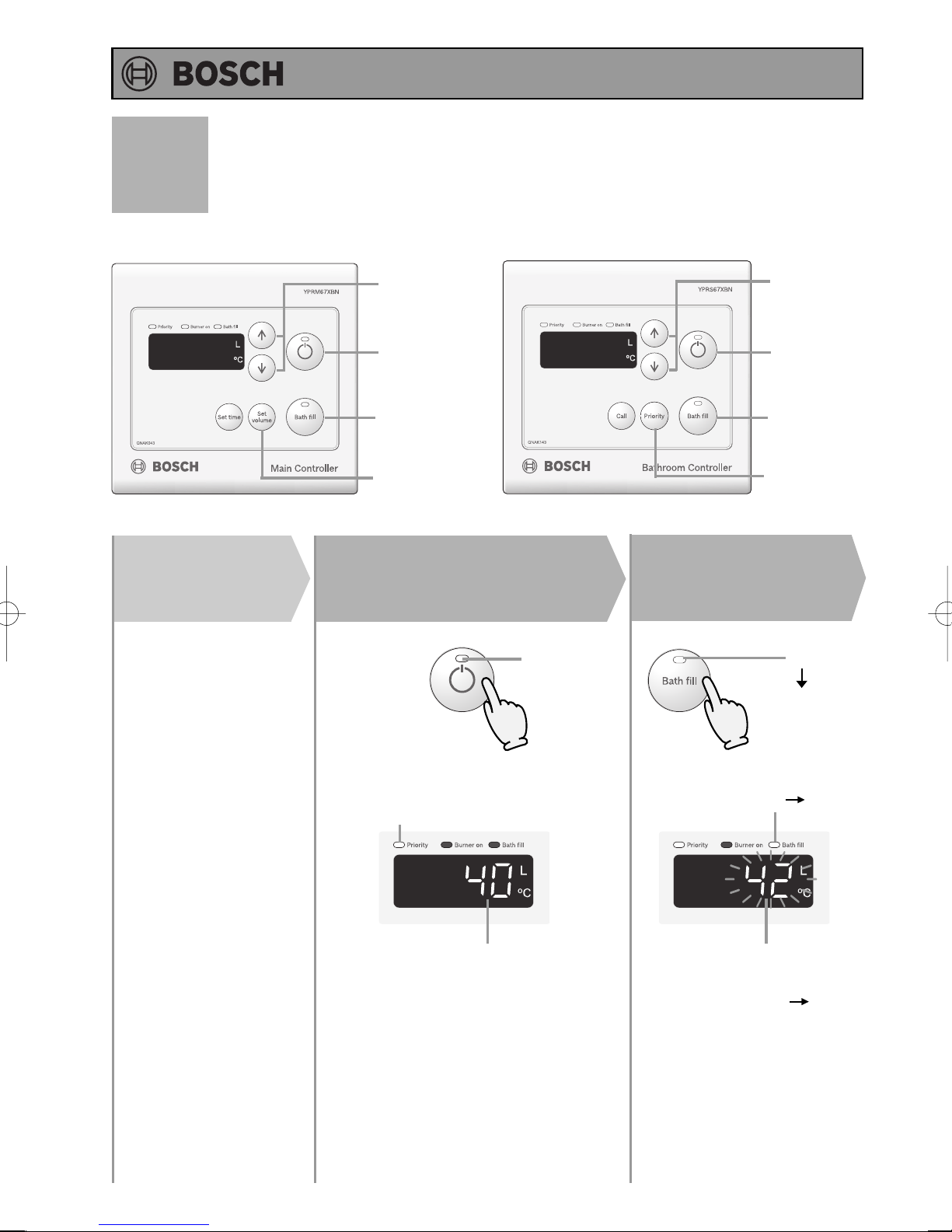
Bath Fill Function
(Main Controller)
Preparation
Plug the bath drain.
(Bathroom Controller)
3
1
2
4
(Starting with the operation off)
Press the
Operation Button
1
On
Press the Bath
Fill Button
2
3
1
2
4
On
10 seconds
after flashing.
18
The temperature will be displayed
on the remote control thermostat.
On
Previous set temperature
(Eg.:40
°C)
Flashes for 10 sec.
Bath Fill temperature
(Eg.:42°C)
Flashes for 10 sec.
On
On
Page 19
Operating Instructions
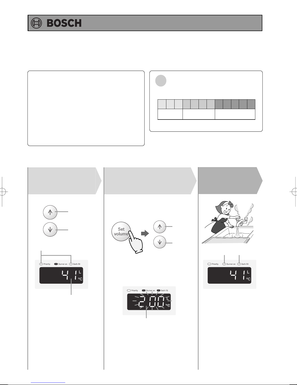
Filling Up the Bath
In order to run a warm bath, push the bath fill
button and open the hot water tap of the bath.
When the bath has reached the volume set
on the controller, an alarm sounds and the hot
water supply will stop automatically.
Once the bath fill is complete, please close
the tap as the water heater cannot operate
until this is done.
To set the Bath Fill Volume:
Set temperature.
3
Always check
temperature setting
(
before use.
)
Hot
Adjust bath fill
4
volume setting.
Press the Bath Fill button (the setting
will flash on the display) and adjust
with the setting buttons.
Water Temperature
The temperatures settings below are only examples. The
:
temperature setting necessary will depend on the usage,
(°C
the length of piping or seasons.
37 38 39 40 41 42 43 44 45 46 47 48
Warmer
* Initial factory setting: 40°C
HotWarm
Turn on hot
5
water.
)
Cold
Check the indicator lights.
Bath Fill temperature
Increase
Decrease
OnOn
Choose the bath fill volume setting from the
following options: 40 - 80 (In 20 litre intervals),
120 - 200 (In 40 litre intervals), or 250 - 650
(In 50 litre intervals).
* Initial factory setting: 160 litre.
Bath fill volume setting will be flashing
(Eg. 200 litre.)
* The level can only be adjusted while the
indicator is flashing.
* After ten seconds, the remote
will again display the temperature.
* For Bathroom controller.
To alter the bath fill volume press the
priority button after the bath fill button.
19
Page 20
Operating Instructions
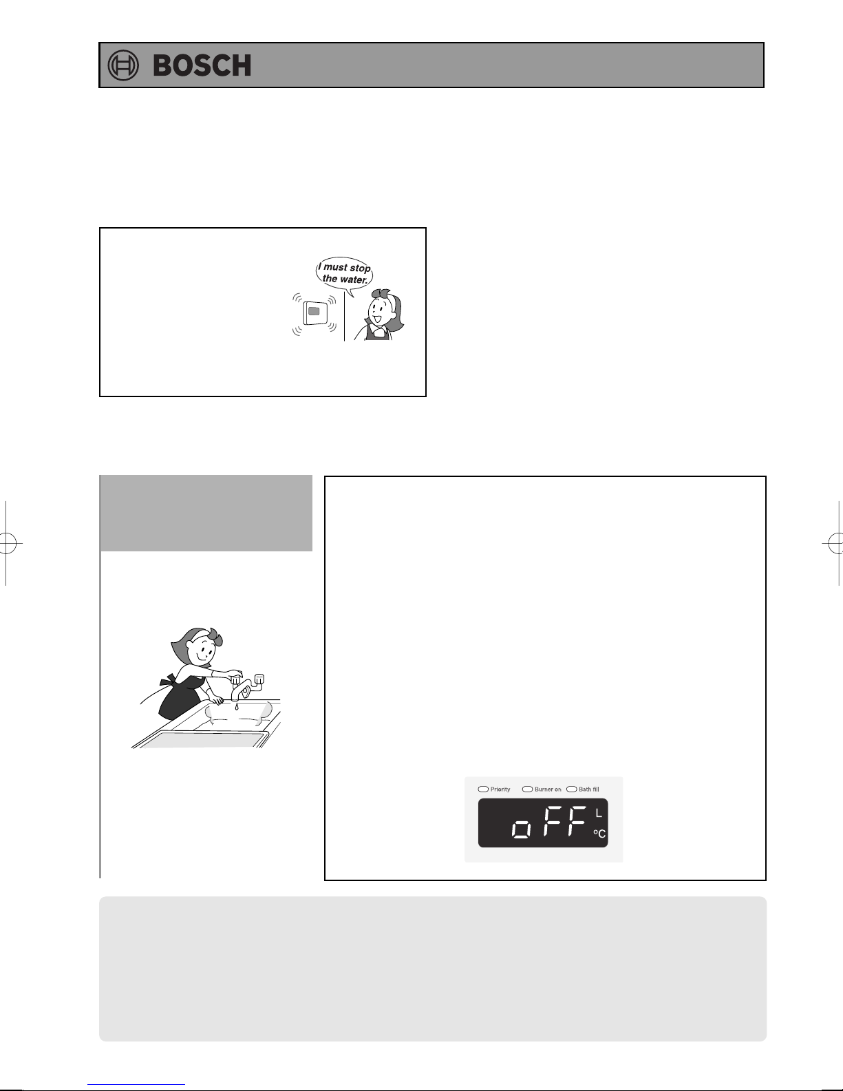
An alarm will sound for ten
seconds when the flow
reaches the set level.
And the hot water will stop automatically.
Turn off the hot
water when the
6
alarm sounds.
The alarm will sound when
the set level has been
reached. Stop the water.
* When using hot water at another hot water outlet, also
turn it off.
<When you turn off the hot water supply>
• Bath fill temperature indicator turns off. (within approx. 30
seconds).
<If you do not turn off the hot water supply>
The equipment automatically runs the water to check if the hot
water supply has been turned off.
<When approx. 10 minutes passes without turning off the
hot water supply the sound is played>
The following screen appears, so turn off all the hot water
supplies and then press the buth fill button.
* Do not open the hot water supply until the Bath fill temperature
indicator goes off.
The setting temperature becomes the bath fill temperature after the bath fill was used.
If the bath fill is being used to indicate when a bath is full:
• If any hot water is being used besides what is going into the bath, the alarm will sound before
the bath is full.
• If there was water in the bath before the fill began, the bath may overflow.
• If there was water in the bath before the fill began, the temperature in the bath after it is full
may be different from the temperature setting.
20
Page 21
Call Function
(Bathroom Controller)
Operating Instructions
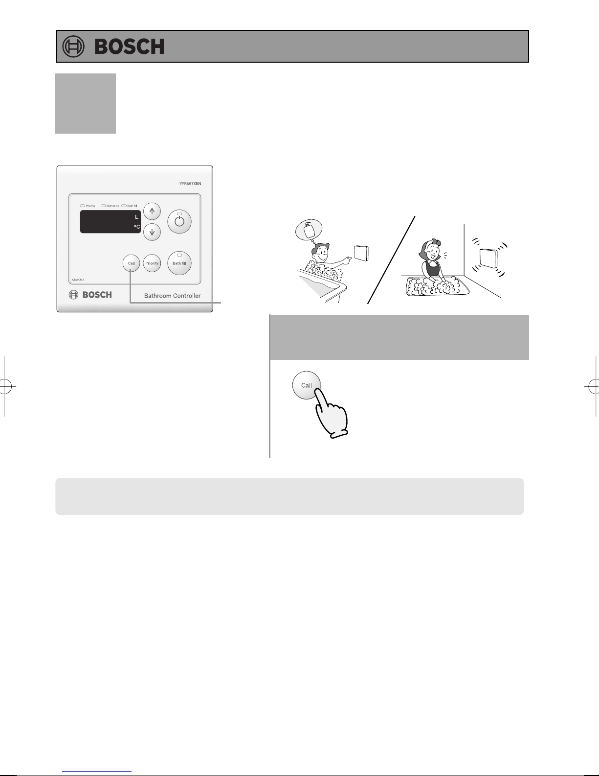
The call button can be used to sound an alarm at the
Main Controller.
(Conversation is not possible as it is not an intercom.)
Sham
poo
1
Pi!
Pi!
Pi!
1
Press the call button.
The alarm sounds for as long as
the button is pressed.
The call button can be used regardless of whether the operation button is turned “on” or “off”.
•
21
Page 22
Operating Instructions
Frost Protection
CAUTION
* Damage can occur from frozen water within the device and pipes even in warm environments.
Be sure to read below for appropriate measures.
* Repairs for damage caused by freezing are not covered by the warranty.
Freezing is prevented within the device automatically by the freeze-prevention heater
Freezing cannot be prevented when the power plug is unplugged. Ensure that the appliance is
plugged in and switched on at all times.
(Freezing will be prevented regardless of whether the operation switch is ON or OFF.)
* The freeze prevention heaters will not prevent the plumbing external to the unit from freezing.
Protect this plumbing with insulation, heat tape or electric heaters, solenoids, or pipe covers.
Take the measures below for extremely cold temperatures*.
(outside temperature including wind chill factor less than -15°C)
This method can protect not only to the heater, but also to the water supply,
water piping and mixing valves.
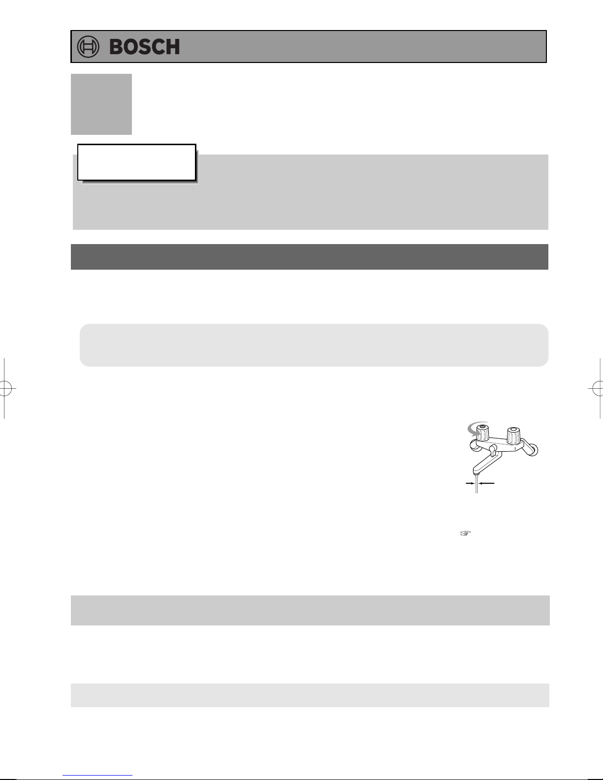
1. Turn the unit off with the Operation Button on the Remote Controller.
2. Close the gas supply valve.
3. Open a hot water fixture, and keep a small amount of hot water running
(400cc / minute or about 4mm thick).
* If there is a mixing valve, set it to the highest level.
4. The flow may become unstable from time to time. Check the flow 30 minutes later.
* In general, it is not advisable to run water through the unit when it is OFF ( p. 6),
but in this case freeze prevention is more important.
Hot Water Fixture
4mm thick
If water will not flow because it is frozen
1. Close the gas and water valves.
2. Turn off the operation button.
3. Open the water supply valve from time to time to check whether water is running.
4. When the water is flowing again, check for water leaks from the equipment and piping before using.
If the heater or the piping is frozen, do not use the heater or it may get damaged.
22
Page 23
Operating Instructions
Check
Check
Check
Check
Regular Maintenance
Periodic Inspection
CAUTION
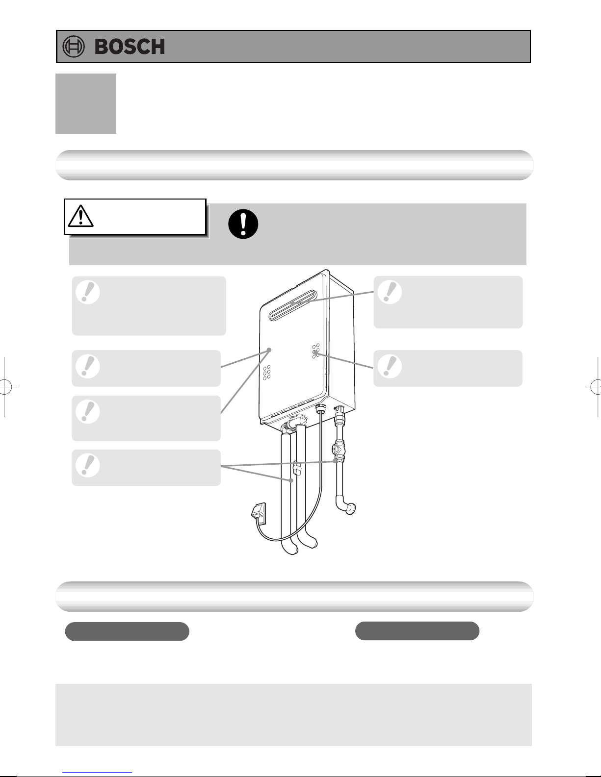
For laundry, newspaper,
timber, oil, spray cans
and other combustible
materials.
For abnormal sounds
during operation.
For abnormalities in
external appearance,
discoloration or flaws.
For water leaks from the
equipment and piping.
Be sure to do.
To prevent burns or scalding, turn off the operation
button and wait until the equipment cools before
performing maintenance.
Check
Check
For dust and soot in
the flue collar.
For dust or debris in
the air inlet.
Periodic Maintenance
Equipment
Wipe the outside surface with a wet cloth, then dry the
surface. Use a neutral detergent to clean any stains.
• Do not use benzene, oil or fatty detergents to clean the remote controller;
deformation may occur.
• YPRS67XBN, YPRP62XBN are water resistant but not water proof. Keep it as dry as possible.
YPRM67XBN is not water resistant.
Remote Controller
Wipe the surface with a wet cloth.
23
Page 24
Operating Instructions
Periodic Maintenance
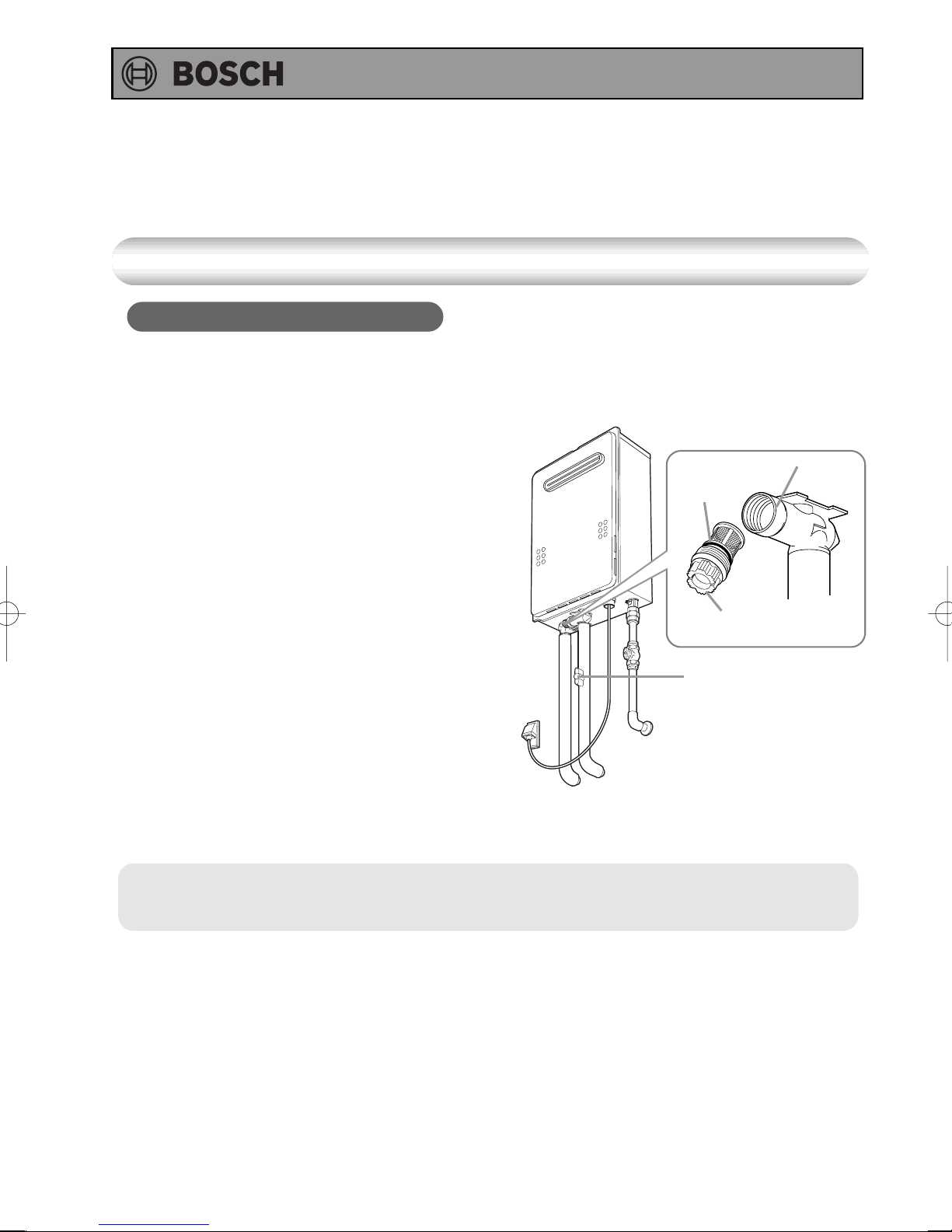
Water Drain Valve (with Water Filter)
If the water drain valve (with water filter) is covered with debris, the hot water may not run
smoothly, or the unit may put out cold water. Check and clean the filter as explained below.
* To avoid burns, wait until the equipment cools down before draining the water.
The appliance will remain hot after it is turned off.
1. Close the water supply valve.
2. Open all hot water fixtures.
3. With a bucket ready, remove the inlet and outlet
drain plugs (about 1 L. will drain out)
4. Take the water drain valve (with water filter) out
of the inlet. (See illustration to right).
5. Clean the water drain valve (with water filter) with
a brush under running water.
6. Replace the water drain valve (with water filter)
and close the drain plugs.
(Take care not to lose the packing.)
7. Close all hot water fixtures.
8. Open the water supply valve and check that
water does not leak from the drain plugs or water
drain valve (with water filter).
* This water heater should be serviced by an authorised person at regular intervals not
exceeding 2 years.
Packing
Water drain valve
(with water filter)
Water Supply
Valve
Inlet
24
Page 25
Operating Instructions
Troubleshooting
Initial Operation
Unit does not attempt to ignite
when water is running.
Unit attempts to ignite but fails
Hot water is not available
when a fixture is opened.
No water is available when
a fixture is opened.
• Check for reversed plumbing or crossed pipes.
• Check the water drain valve filter. (
• Reset unit and try again. There may be air in the gas line.
• Have a professional check the gas supply pressure.
p.24)
Temperature
• Are the gas and water supply valves fully open?
• Is the water supply cut off?
• Is the hot water fixture sufficiently open?
•
Is the gas being cut off by the gas meter?
(Can other gas devices such as stoves be used?)
• (For LP) Is there enough gas in the tank?
(Can other gas devices such as stoves be used?)
• Is the water drain valve filter clogged? ( p.24)
• Is the operation button turned on?
• Is the water supply cut off?
• Is the heater frozen?
The hot water is not the correct
temperature.
Water takes time to become hot
when turning the hot water fixture.
The water is too hot.
The water is not hot enough.
• Is the hot water fixture sufficiently open?
• Have you allowed enough time for the cold water in the
pipes to drain out?
• Are the gas and water supply valves fully open?
• Is the water temperature setting appropriate?
(
• If the water supply temperature is high, it is possible
for the temperature to be higher than the temperature
set on the remote controller.
• If only a small amount of hot water is demanded, it is
possible for the temperature to be higher than the
temperature set on the remote controller.
• Are the gas and water supply valves fully open?
• Is the water temperature setting appropriate?
( p.14 and p.15)
p.14 and p.15)
(Continued)
25
Page 26
(Continued)
Operating Instructions
The water is cold when only a
single fixture is open.
Fluctuations in hot water
temperatures.
Amount of Hot Water
The amount of hot water at a
certain fixture is not constant.
• The unit will not heat the water if the flow rate is less than
2.5 litre per minute.
Open the fixture more or open other fixtures so that a greater
flow passes through the unit, and the unit should begin
heating again.
• Set water temperature at 48°C to 50°C. This will allow you
to use a higher flow of hot water thus meeting the minimum
flow requirement of 2.5 L/min.
• Clean the water filter of any debris ( p.24)
• When hot water is demanded at other fixtures, the amount
available may be reduced. The maximum flow available
from YS2180 RA (5) (P) (5P) is 21 L /min., YS1780 RA (5)
(P) (5P) is 17 L /min. at a 25°C temperature rise.
• Pressure fluctuations and other plumbing conditions can
cause the temperature and pressure at a fixture to be
unstable, but it should stabilize after a short time.
• There are some types of hot water taps that discharges large
volumes of hot water at first but stabilize after time.
•To keep the temperature stable, the heater limits the
amount of water that can flow through it to a small amount
initially, but the amount increases over time.
The amount of hot water in the
bath is less/more than the set
amount.
The bath fill alarm does not
sound even when filled to the set
amount.
Amount of hot water available
has decreased over time.
The light on the operation button
does not come on.
26
• When hot water is used for other fixtures while filling the
bath, the bath will not fill as much.
• If there is water in the bath already, or when filling is
stopped and restarted, the bath will fill more.
• The bath fill alarm is set to sound when hot water
is continuously discharged for the set volume of water.
If mixing valves are used, or if cold water is mixed with hot
water at the fixture, the bath will fill more than the setting
of the bath fill function.
• Is the water filter clogged? ( p.24)
Remote Controller
• Has there been a power failure?
• Is the power connected properly?
(Continued)
Page 27
(Continued)
Operating Instructions
Clock shows “0:00”.
The water temperature changes
after a power failure or when the
power is disconnected.
The plastic on the surface or buttons
of the remote controller has torn,
peeled, or air bubbles inside.
The fan can be heard after
operation is stopped.
A motor can be heard when turning
the unit ON or OFF, when opening
or closing a fixture, or after the unit
has been running for a while.
• If the power is disconnected for any reason, when the
power is reconnected, the clock on the display screen
shows “0:00”, indicating that it needs to be reset. ( p.13)
• The temperature setting and the bath fill setting may
both need to be reset after a power outage.
• The surface of the remote controller is affixed with a
protective sheet (to prevent surface scratching, etc.) at
time of shipment. This sheet can be removed or left as it
is. When leaving the protective sheet on, areas frequently
touched may tear or peel. However, the remote controller
will not malfunction from water entering such torn or
peeled areas. To restore the appearance of the remote
controller surface, simply remove the protective sheet.
Sounds
• These noises indicate the proper operation of devices
which are designed to let the unit reignite more quickly,
and ensure the water temperature is stable.
The heater stops burning during
operation.
collar on a cold day.
Other
• Are the gas and water supply valves fully open?
• Is the water supply cut off?
• Is the hot water fixture sufficiently open?
• Is the gas being cut off by the gas meter?
(Can other gas devices such as stoves be used?)
• (For LP) Is there enough gas in the tank?
(Can other gas devices such as stoves be used?)
• This is normal. The white smoke is actually steam.White smoke comes out of the flue
(Continued)
27
Page 28
(Continued)
The hot water is turbid.
The water appears blue
The bath tub/wash-basin has turned
blue.
Operating Instructions
This is harmless. Small bubbles appear as the air in the water
•
is heated and depressurized rapidly to atmospheric pressure.
•
Coloration to a blue colour may be noticed from small traces of
copper ion contained in the water and fat (furring). However,
there are not problems concerning health. Coloration of the
bath tub/wash-basin can be prevented by cleaning frequently.
åÃè·ï\é¶Ç Ç®íÇÇÇæÇÇ¢ åÃè·ï\é¶Ç Ç®íÇÇÇæÇÇ¢
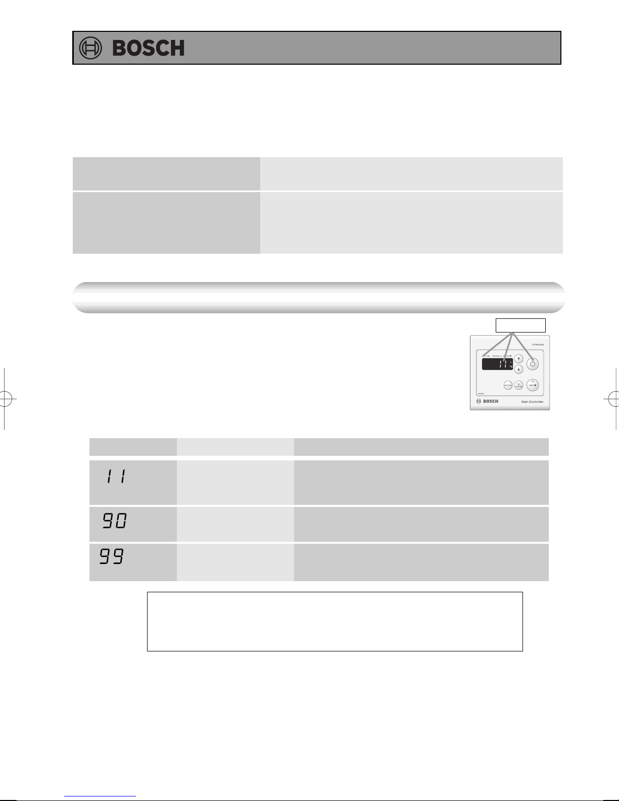
Check for an Error Code
If there is a problem with the unit, a numerical error code will flash on
the remote controller.
If this occurs, take appropriate measures as listed below.
When an error code appears, the display and the operation light
will flash together.
Error Code Cause Action
Ignition error
Abnormal combustion,
low gas supply pressure
Abnormal combustion
Check whether the gas valve is open. Press the operation button to
turn the unit off, open a hot water fixture, and turn the unit back on.
If the flashing number doesn't return the problem is solved.
Have a professional check the gas supply pressure.
Contact Bosch 1300-30-70-37.
Contact the installer or Bosch Service Department for
assistance.
Flashing
Main Controller
Contact Bosch if:
• Any other error code appears.
• An error code is indicated again after the above actions were followed.
• There are any other questions.
28
Page 29
Operating Instructions
Follow-up Service
Requesting Service
First follow the instructions in the troubleshooting section ( p.25 to p.28).
If the error is not corrected, contact Bosch Service Department at 1300-30-70-37.
We will need to know:
The Models .............. YS2180RA YS2180RA5 YS2180RAP YS2180RA5P
YS1780RA YS1780RA5 YS1780RAP YS1780RA5P
Date of purchase ..... (see the warranty)
Details of problem ... (flashing error codes, etc., in much detail as possible)
Your name, address, and telephone number
Desired date of visit
Warranty
For repairs after the warranty period, there will be a charge on any service, and service will only
be performed if the unit is deemed repairable.
See warranty Document on page 35.
Period of Time for Stocking Repair Parts
Bosch will stock repair and maintenance parts for this unit within ten (10) years of the date of
original manufacture.
Reinstallation
If you want to reinstall the appliance at a different location, confirm that the gas and power
supply indicated on the data plate are available at the new location. If you are not sure, consult
the local utility company.
If you move to a region that uses a different type of gas, conversion and adjustment of the
appliance will be necessary.
29
Page 30
Operating Instructions
Specifications
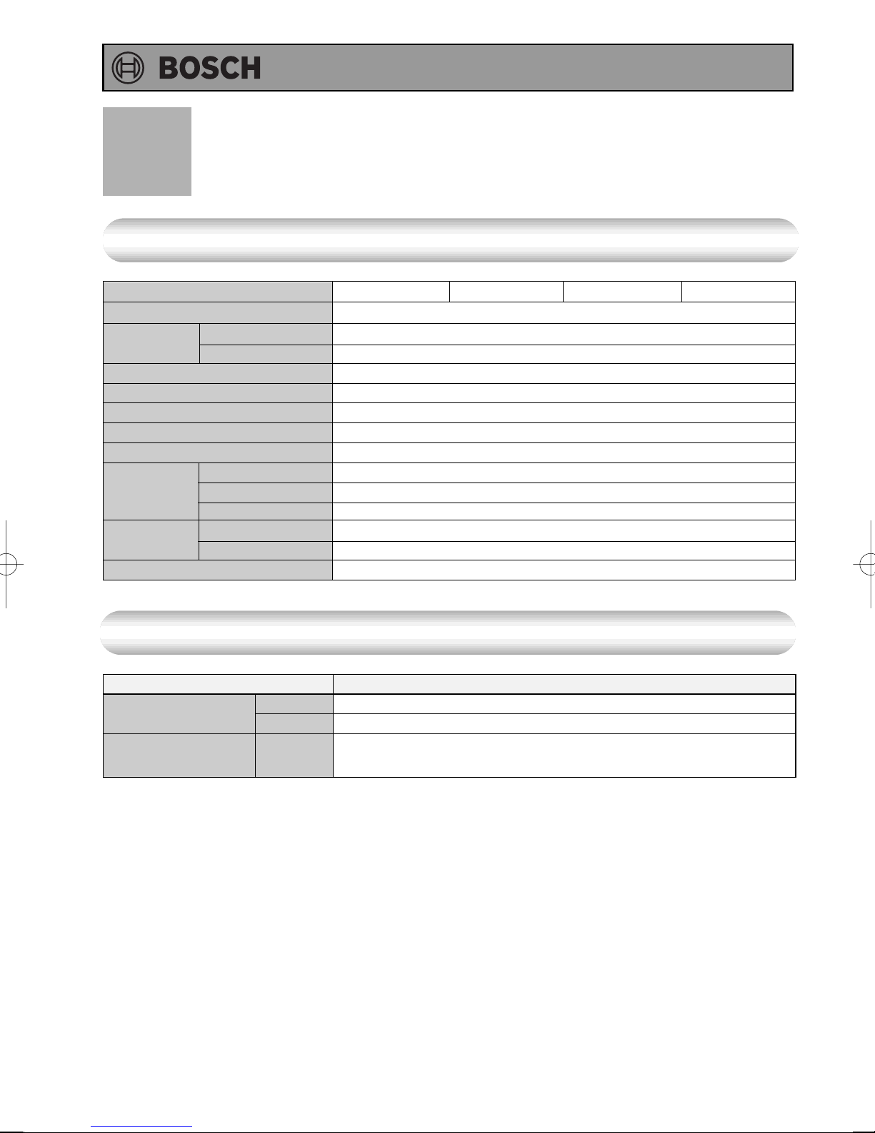
Specifications
Model Name
Approval certification number
Type
Operating Pressure
Minimum Flow Rate
Dimensions
Weight
Water Holding Capacity
Connection
Sizes
Power Supply
Accessories
Item
Gas
Consumption
Maximum Hot Water
Capacity
Installation
Air Supply/Exhaust
Water Inlet
Hot Water Outlet
Gas Inlet
Supply
Consumption
NG
LP
25°C Rise
YS2180RA
520mm (Height) x 350mm (Width) x 170mm (Depth)
NG:39.4W LP:45.4W Freeze Prevention 129W
YS2180RA5
SAI-400151
Outdoor, Wall Mounted
Power Flue
200 -1,000 kPa
2.5 L/min.
15 kg
0.5 L
R 3/4 (20mm)
R 3/4 (20mm)
R 3/4 (20mm)
230 / 240 VAC (50Hz)
Anchoring Screws
YS2180RAP
Performance
Maximum Performance
159 MJ/hr
158 MJ/hr
21 L/min.
YS2180RA5P
30
Page 31
Operating Instructions
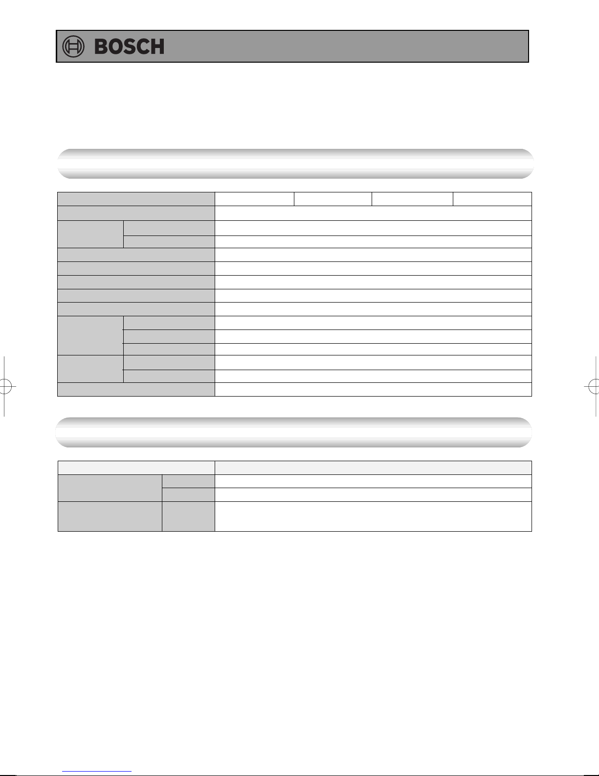
•Specifications may be changed without prior notice.
• The capacity may differ slightly, depending on the water
pressure, water supply, piping conditions, and water temperature.
Specifications
Model Name
Approval certification number
Type
Operating Pressure
Minimum Flow Rate
Dimensions
Weight
Water Holding Capacity
Connection
Sizes
Power Supply
Accessories
Item
Gas
Consumption
Maximum Hot Water
Capacity
Installation
Air Supply/Exhaust
Water Inlet
Hot Water Outlet
Gas Inlet
Supply
Consumption
NG
LP
25°C Rise
YS1780RA
520mm (Height) x 350mm (Width) x 170mm (Depth)
NG:33.3W LP:36.5W Freeze Prevention 129W
YS1780RA5
SAI-400151
Outdoor, Wall Mounted
Power Flue
200 -1,000 kPa
2.5 L/min.
14 kg
0.5 L
R 3/4 (20mm)
R 3/4 (20mm)
R 3/4 (20mm)
230 / 240 VAC (50Hz)
Anchoring Screws
YS1780RAP
Performance
Maximum Performance
126 MJ/hr
130 MJ/hr
17 L/min.
YS1780RA5P
31
Page 32

Note
Operating Instructions
32
Page 33

Note
Operating Instructions
33
Page 34
Operating Instructions
WATER QUALITY
All Bosch water heating appliances are constructed from high quality materials and
components and all are certified for compliance with relevant parts of Australian and
New Zealand gas, electrical and water standards.
Whilst Bosch water heaters are warranted against defects, the warranty is conditional
upon correct installation and use, in accordance with detailed instructions provided
with the heater. In the case of the water supplied to the heater, it is important that the
water quality be of acceptable standard.
The water quality limits/parameters listed in water quality table are considered
acceptable and generally, Australian and New Zealand suburban water supplies fall
within these limits/parameters.
In areas of Australia and New Zealand where water may be supplied, either fully or
partly, from bores, artesian wells or similar, one or more of the important limits may well
be exceeded and the heater could, therefore, be at risk of failure.
Where uncertainty exists concerning water quality, intending appliance users should
seek a water analysis from the water supplying authority and in cases where it is
established that the water supply does not meet the quality requirements of the water
quality table, the Bosch warranty would not apply.
WATER QUALITY TABLE
Maximum levels
pH Saturation Total Chlorides Sodium Iron
Index(LSI) Hardness
(langelier)
6.5-9 +0.4 to 200mg/l 250mg/l 180mg/l 1mg/l
Minus 1.0
@65C
34
Page 35

Operating Instructions
Robert Bosch (Australia) Pty Ltd (Bosch)
Manufacturer’s Warranty
(Applicable for purchases from 1 January 2012)
All Bosch hot water units are carefully checked, tested and subject to stringent quality controls.
1. Warranty
Bosch offers, at its option, to repair or exchange this Bosch hot water unit or the relevant part
listed in clause 2 below at no charge, if it becomes faulty or defective in manufacture or materials
during the warranty period also stated in clause 2. This warranty is offered in addition to any
other rights or remedies held by a consumer at law.
2. Warranty periods & coverage
(a) Domestic applications: 3 years (parts and labour)
(b) Heat exchangers used in domestic applications: 10 years (parts only)
(c) Commercial applications: 12 months (parts and labour)
(d) Heat exchangers used in commercial applications: 5 years (part only)
All warranty periods commence on the date of purchase of the hot water unit by the end-user.
However, where the date of purchase by the end-user is more than 24 months after the date of
manufacture, all warranty periods will automatically commence 24 months after the date of
manufacture.
3. Warranty exclusions
This warranty is VOID if any damage to or failure of the hot water unit is caused wholly or partly
by:
(a) faulty installation
(b) neglect, misuse, accidental or non-accidental damage, failure to follow instructions
(c) use of the unit for purposes other than which it was designed or approved
(d) unauthorised repairs or alterations to the unit without Bosch’s consent
(e) use of unauthorised parts and accessories without Bosch’s consent
(f) use of non-potable water or bore water in the hot water unit (see product instructions for
further details)
(g) continued use after a fault becomes known or apparent.
This warranty DOES NOT include:
(a) costs of consumables or accessories
(b) wear and tear, normal or scheduled maintenance
(c) to the extent permitted by law, any damage to property, personal injury, direct or indirect loss,
consequential losses or other expenses
(d) changes in the condition or operational qualities of the hot water unit due to incorrect storage
or mounting or due to climatic, environmental or other influences.
NOTE: Any service call costs incurred by the owner or user of the hot water unit for any matter
not covered by the terms of this warranty will not be reimbursed by Bosch, even if those costs are
incurred during the warranty period. If the hot water unit is located outside the usual operating
area of a Bosch service agent, the agent’s travel, freight or similar costs are not covered by this
warranty and must be paid by the owner or user of the hot water unit.
4. Warranty conditions
(a) Proof of purchase may be required.
(b) The hot water unit must be installed by an authorised and licensed installer.
(c) Proof may be required of the date of installation and correct commissioning of the hot water
unit has been carried out to Bosch’s satisfaction (such as a certificate of compliance).
(d) Repair or replacement of the hot water unit or any parts under this warranty does not
lengthen or renew the warranty period.
35
Page 36
Operating Instructions
(e) This warranty is not transferable and is only offered to the original purchaser of the hot water
unit.
(f) No employee or agent of Bosch is authorised to amend the terms of this warranty.
(g) This warranty only applies to Bosch hot water units purchased from an authorised reseller
and installed in Australia or New Zealand.
(h) To the extent that any condition or warranty implied by law is excludable, such condition or
warranty is excluded.
5. How to lodge a warranty claim and warranty procedure
(a) Warranty claims must be made with the Bosch Customer Contact Centre (Australia: ph 1300
307 037; New Zealand: ph 0800 543 352). Please be ready to provide the model and serial
numbers, date of installation, purchase details and a full description of the problem.
Warranty claims must be made before the end of the warranty period.
(b) All warranty service calls must conducted by an authorised Bosch service agent.
(c) Invoices for attendance and repair of a hot water unit by third parties not authorised by Bosch
will not be accepted for payment by Bosch.
6. Privacy Act 1988 (Cth)
A customer's personal information collected during warranty claims may be used for the
provision of customer support, for the provision of information about products and services and
for other marketing activities undertaken by Bosch and its Bosch Service Agents who are
authorised to carry out warranty repairs on behalf of Bosch (Purpose). Bosch is committed to
protecting the privacy of its customers' personal information. It will act in compliance with
the National Privacy Principles and
personal information to third parties other than for the Purpose. A customer can object at any
time to the use of their personal information for the Purpose. Bosch will cease to use a
customer's personal information accordingly if an objection is made.
Privacy Act 1988
(Cth). Bosch will not forward customers'
7. Bosch contact details
If you have any questions about this warranty or to lodge a warranty claim, please contact:
Robert Bosch (Australia) Pty Ltd
1555 Centre Road, Clayton, Victoria 3168
Tel: Australia: 1300 307 037
Tel: New Zealand: 0800 543 352
IMPORTANT NOTE FOR AUSTRALIAN CONSUMERS
Our goods come with guarantees that cannot be excluded under the Australian Consumer Law.
You are entitled to a replacement or refund for a major failure and for compensation for any other
reasonably foreseeable loss or damage. You are also entitled to have the goods repaired or
replaced if the goods fail to be of acceptable quality and the failure does not amount to a major
failure.
36
 Loading...