

Bosch WTW86560AU Repair Instructions

Repair Instructions Laundry - Repair Instruction;T22 - Table of content
2013-10-23 / DIS 113_58300000133444_ara_en_l Repair Instructions Laundry Repair Instruction;T22 Page 1 of 35
1 Concerning this document 2
1.1 Purpose and target group..................................................... 2
1.2 Other applicable documents..................................................2
2 Safety 3
2.1 Qualification........................................................................... 3
2.2 Information in warnings......................................................... 3
2.3 Basic safety instructions........................................................4
2.4 Basic warning instructions.....................................................5
3 Design and function 7
3.1 Fascia.....................................................................................7
3.2 Conductivity measurement.................................................... 8
3.3 Condensate water container..................................................9
3.4 Temperature control with fan (cooling air)........................... 10
3.5 Heat pump circuit................................................................ 11
3.6 Automatic cleaning function.................................................12
4 Fault diagnosis 13
4.1 Malfunctions.........................................................................13
4.2 Result faults.........................................................................14
4.3 Leaks....................................................................................15
4.4 Odours................................................................................. 16
5 Test 17
5.1 Starting / ending demo programme..................................... 17
5.2 Checking electrodes for measuring conductance................ 18
5.3 Checking interior light..........................................................19
5.4 Read out fault memory........................................................ 20
6 Repairs 21
6.1 Cleaning the heat pump...................................................... 21
6.2 Installing conversion kit 743988.......................................... 22
6.3 Replacing motor...................................................................23
6.4 Replacing left / right side panel...........................................24
6.5 Replacing rollers..................................................................26
6.6 Removing / installing the cooling-air panel.......................... 27
6.7 Opening / closing refrigeration circuit.................................. 28
6.8 Replacing compressor......................................................... 29
6.9 Replacing fluff filter..............................................................30
6.10 Removing / installing front panel......................................... 32
6.11 Cleaning the condenser.......................................................33
6.12 Removing / installing drum bearing..................................... 34
6.13 Transporting the appliance..................................................35

Concerning this document
2013-10-23 / DIS 113_58300000133444_ara_en_l Repair Instructions Laundry Repair Instruction;T22 Page 2 of 35
1.1 Purpose and target group
These repair instructions include information on troubleshooting and repairs.
This information supports the following employees in customer service:
• Service technicians who repair domestic appliances
• Technical storemen in the spare-parts warehouse who determine the required
spare parts
• Call centre employees who take orders
1.2 Other applicable documents
The following documents include additional relevant repair information:
• Documents “Design and function” and “Customer advice”
• Test programmes
• Circuit diagrams
• Exploded drawings
• Parts lists
• Repair videos
Safety
2013-10-23 / DIS 113_58300000133444_ara_en_l Repair Instructions Laundry Repair Instruction;T22 Page 3 of 35
2.1 Qualification
In Germany repair work may be performed only by electrical engineers who have
been trained by BSH or a centre authorised by BSH.
In all other countries repair work may be performed by comparably trained
technicians only.
2.2 Information in warnings
2.2.1 Danger levels and warning symbols
Warnings are provided in this document with danger levels and warning symbols.
The danger levels consist of a symbol and a warning word. The warning word
identifies the severity of the danger.
Danger level Meaning
Failure to observe the warning will result in death or serious injuries.
Failure to observe the warning may result in death or serious
injuries.
Failure to observe the warning may result in minor injuries.
Failure to observe the warning may result in damage.
Table 1: Danger levels
Warning symbols are symbolic illustrations which indicate the type of danger.
Symbol Meaning
General warning
Danger of electric shock
Risk of explosion
Risk of cut injuries
Safety
2013-10-23 / DIS 113_58300000133444_ara_en_l Repair Instructions Laundry Repair Instruction;T22 Page 4 of 35
Symbol Meaning
Risk of crush injuries
Danger - hot surfaces
Danger - strong magnetic
Danger - non-ionising radiation
Table 2: Warning symbols
2.2.2 Structure
Warnings in this document have a uniform appearance and structure.
Type and source of danger!
Consequences of ignoring the warning.
► Actions to protect from danger.
The following example shows a warning which warns of an electric shock:
High voltage!
Death by electric shock.
► Disconnect appliance from grid.
► Discharge high-voltage capacitor.
2.3 Basic safety instructions
These repair instructions form the basis for a systematic and safetyconscious procedure for the repair of domestic appliances.
2.3.1 Measures to be taken for each repair
The following dangers are associated with the repair of domestic appliances:
• Danger of electric shock from exposed, live wires and components
• Risk of cut injuries from sharp edges
• Risk of destruction of electronic components by electrostatic discharge
Specific measures prevent injuries and damage. Service technicians are obliged to
take these measures for each repair.
Preventive measures
... against electric shock When carrying out repairs:
• Disconnect appliance from power
supply.
When running tests with power supply
on:
• Use a residual-current-operated circuit-breaker.
• Select protective conductor connection less than standard value.
... to prevent cut injuries • wear protective gloves.
... electronic components • wear earthing wrist strap.
• Discharge capacitors.
Table 3: Measures to be taken for each repair
Safety
2013-10-23 / DIS 113_58300000133444_ara_en_l Repair Instructions Laundry Repair Instruction;T22 Page 5 of 35
2.3.2 Measures to be taken after each repair
State of the appliance Measures
Appliance has been repaired and is
functionally reliable.
• Run tests in accordance with VDE
0701 or comparable national regulations.
• Conduct a performance test.
• Document repair work, tests, measured values and functional reliability.
Appliance is still defective and not functionally reliable.
• Clearly identify appliance as "not
functionally reliable".
• Inform customer in writing about the
lack of functional safety.
Table 4: Measures to be taken after each repair
2.4 Basic warning instructions
Exposed, live components!
Death from electric shock.
► Disconnect the appliance from the power supply.
► Do not touch housing, frame or components.
► If running tests while the power is on, always use a residual
current circuit-breaker.
► Ensure that the resistance of the protective conductor does not
exceed the standardised value.
Discharge current of charged capacitors!
Death from electric shock. Risk of injury from startle response.
► Disconnect the appliance from the power supply.
► Discharge capacitors.
Exposed, defective components live!
Death from electric shock.
► Disconnect the appliance from the power supply.
► Do not touch housing, frame or components.
► If running tests while the power is on, always use a residual
current circuit-breaker.
► Ensure that the resistance of the protective conductor does not
exceed the standardised value.

Safety
2013-10-23 / DIS 113_58300000133444_ara_en_l Repair Instructions Laundry Repair Instruction;T22 Page 6 of 35
Sharp edges!
Cut injuries.
► Wear protective gloves.
► Wear personal protective equipment.
Touching electrostatically sensitive components!
Destruction of components.
► Apply electrostatic protection system.
► Observe measures to protect the electrostatically sensitive
components.
Unnecessary replacement of sensitive components!
Destruction of components.
► Systematically check components before replacing them.
► Do not replace components without reason.
► Observe technical documentation.
Design and function
2013-10-23 / DIS 113_58300000133444_ara_en_l Repair Instructions Laundry Repair Instruction;T22 Page 7 of 35
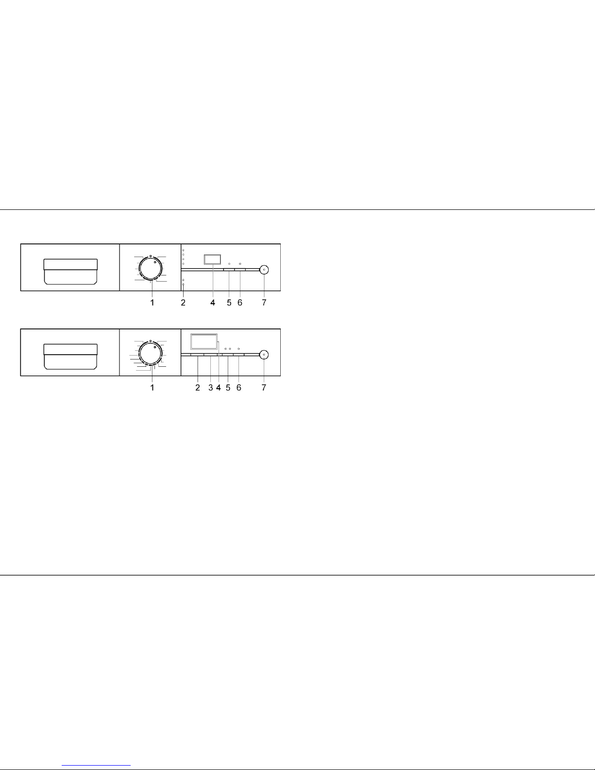
3.1 Fascia
Graphic 1: Fascia
Graphic 2: Fascia
1 Programme selector 5 Low heat / super low heat button
2 Menu button 6 Easy-iron / Anti-crease button
3 Change button 7 Start / stop button
4 LCD display
Design and function
2013-10-23 / DIS 113_58300000133444_ara_en_l Repair Instructions Laundry Repair Instruction;T22 Page 8 of 35
3.2 Conductivity measurement
If the load is low, conductivity cannot be measured with precision.
See circuit diagrams: Washing not dry.
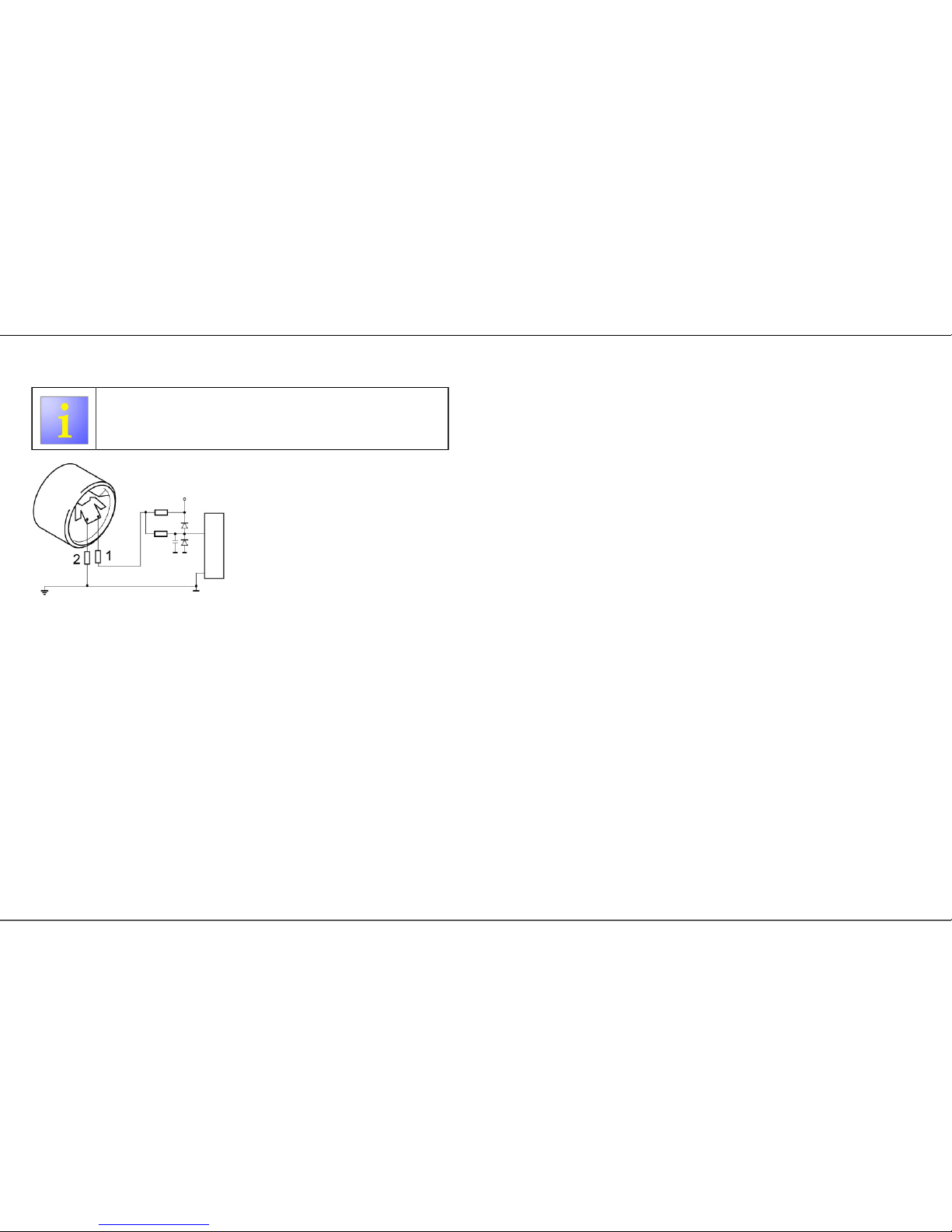
Graphic 3: Conductivity measurement in the appliance
1 Conductivity electrode 2 Counter-electrode
The conductivity measurement is a moisture-dependent control.
The conductivity measurement is based on the physical principle that textiles
have a conductivity which varies depending on the moisture. Damp washing has
a higher conductivity than dry washing. The conductivity is measured when the
washing touches an electrode and a counter-electrode which form a measurement
section.
The electrodes are in the end shield. During the drying process the items of
washing continuously touch the electrodes. The preselected degree of drying is
reached when the determined conductance of the washing agrees with a value
specified by the programme selection.
Design and function
2013-10-23 / DIS 113_58300000133444_ara_en_l Repair Instructions Laundry Repair Instruction;T22 Page 9 of 35
3.3 Condensate water container
3.3.1 Structure
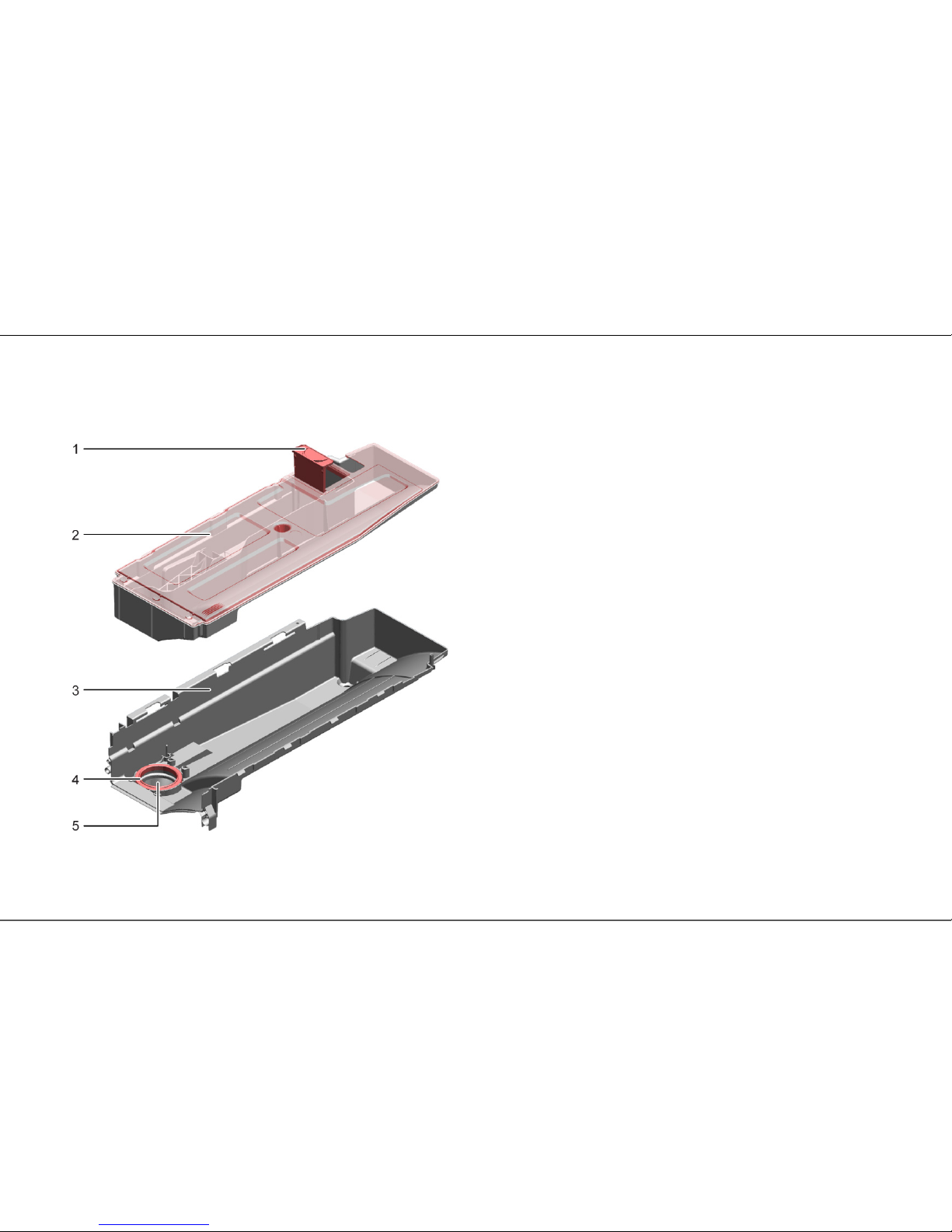
Graphic 4: Components of the condensate water container
1 Filter 3 Tray
2 Drawer 4 Opening
The condensate water container consists of a cover with filter (1) and a chamber
(2) for condensation, as well as a tray (3) with an opening (4) with a downpipe to
the evaporator.
3.3.2 Function
The condensate water is pumped through the filter into the condensate water
container via the condensate pump in the base pan. Fluff in the condensate water
is caught in the filter. The filter is usually cleaned by emptying the condensate
water container, but it can also be removed and cleaned manually. The cleaned
condensate water is collected in one drawer (max. 2 l). The cleaned condensate
water is conveyed through the opening in the tray to the evaporator via a downpipe
and flushes the evaporator.

Design and function
2013-10-23 / DIS 113_58300000133444_ara_en_l Repair Instructions Laundry Repair Instruction;T22 Page 10 of 35
3.4 Temperature control with fan (cooling air)
3.4.1 Structure
The appliance features two NTC sensors: The NTC sensor B31 in the refrigeration
circuit on the compressor and an NTC sensor on the end shield (optional).
The electronic control is connected to the NTC sensors and controls the
components, via electrical connections, which are required to control the
temperature.
3.4.2 Function
The electrical control controls the fan (cooling air) depending on the selected
programme and the transmitted NTC sensor values:
• From an ambient temperature above 30 °C.
• From a temperature on the NTC sensor B31 above 61 °C.
This prevents actuation of the overheating protection OLP (Over Load Protector)
on the compressor.
Design and function
2013-10-23 / DIS 113_58300000133444_ara_en_l Repair Instructions Laundry Repair Instruction;T22 Page 11 of 35
3.5 Heat pump circuit
3.5.1 Structure
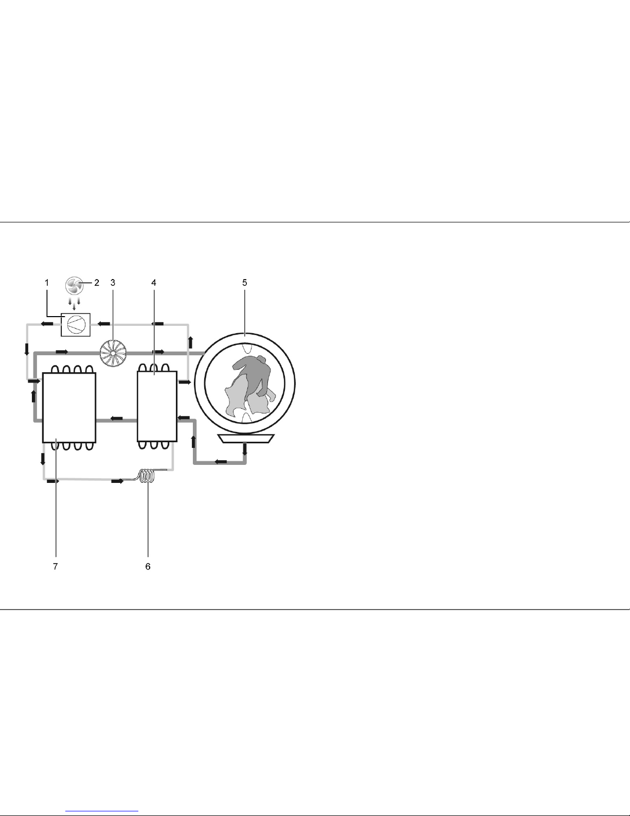
Graphic 5: Components of the heat pump circuit
1 Compressor 5 Drum with washing
2 Fan (cooling air) 6 Capillary tube
3 Fan process air 7 Condenser
4 Evaporator
3.5.2 Function
• The heat pump circuit contains the refrigerant
• The compressor compresses the gaseous refrigerant which is heated in the
process.
• The condenser (7) releases heat into the process air which is then blown by the
process air wheel into the drum.
• The heat dissipation causes the refrigerant to condense.
• The connecting capillaries cause the refrigerant to expand abruptly. As a result,
the pressure and temperature are reduced, but the coolant remains liquid.
• The evaporator now absorbs heat from the moist process air and the coolant
becomes gaseous. The cooling of the moist warm process air causes water to
condense on the fins and then to flow into the base group.
• The compressor now draws the gaseous coolant in again and compresses it
again.
• The fan cools the compressor to prevent the self-locking system (OLP) from
activating.
 Loading...