

Bosch WTVC853PUC Operating And Installation Instructions
Bosch Vision _M300/500/800
Gas Clothes Dryers
Series
iiiiiiiiiiiiiiiiiiiiiiiiiiiiiiiiiiiiiiiiiiiiiiiiiiiiiiiiiiiiiiiiiiiiiiiiiiiiiiiiiiiiiiiiiiiiiiiiiiiiiiiiiiiiiiiiiiiiiiiiiiiiiiiiiiiiiiiiiiiiiiiiiiiiiiiiiiiiiiiiiiiiiiiiii_
iiiiiiiiiiiiiiiiiiiiiiiiiiiiiiiiiiiiiiiiiiiiiiiiiiiiiiiiiiiiiiiiiiiiiiiiiiiiiiiiiiiiiiiiiiiiiiiiiiiiiiiiiiiiiiiiiiiiiiiiiiiiiiiiiiiiiiiiiiiiiiiiiiiiiiiiiiiiiiiiiiiiiiiiii_ii_ i
iiiiiiiiiiiiiiiiiiiiiiiiiiiiiiiiiiiiiiiiiiiiiiiiiiiiiiiiiiiiiiiiiiiiiiiiiiiiiiiiiiiiiiiiiiiiiiiiiiiiiiiiiiiiiiiiiiiiiiiiiiiiiiiiiiiiiiiiiiiiiiiiiiiiiiiiiiiiiiiiiiiiiiiiii_ii__ i
_i_i_i_i_i_i_i_i_i_i_i_i_i_i_i_i_i_i_i_i_i_i_i_i_i_i_i_i_i_i_i_i_i_i_i_i_i_i_i_i_i_i_i_i_i_i_i_i_i_i_i_i_i_i_i_i_i_i_i_i_i_i_i_i_i_i_i_i_i_i_i_i_i_i_i_i_i_i_i_i_i_i_i_i_i_i_i_i_i_i_i_i_i_i_i_i_i_i_i_i_i_i_i_i_i_i_i_i_i_i_i_i_i_i_i_i_i_i_i_i_i_i_i_i_i_i_i_i_i_i_i_i_i_i_i_i_i_i_i_i_i_i_i_i_i_i_i_i_i_i_i_i_i_i_i_i_i_i_i_i_i_i_i_i_i_i_i_i_i_i_ii_
iiiiiiiiiiiiiiiiiiiiiiiiiiiiiiiiiiiiiiiiiiiiiiiiiiiiiiiiiiiiiiiiiiiiiiiiiiiiiiiiiiiiiiiiiiiiiiiiiiiiiiiiiiiiiiiiiiiiiiiiiiiiiiiiiiiiiiiiiiiiiiiiiiiiiiiiiiiiiiiiiiiiiiiiii_ii
iiiiiiiiiiiiiiiiiiiiiiiiiiiiiiiiiiiiiiiiiiiiiiiiiiiiiiiiiiiiiiiiiiiiiiiiiiiiiiiiiiiiiiiiiiiiiiiiiiiiiiiiiiiiiiiiiiiiiiiiiiiiiiiiiiiiiiiiiiiiiiiiiiiiiiiiiiiiiiiiiiiiiiiiii_ii
iiiiiiiiiiiiiiiiiiiiiiiiiiiiiiiiiiiiiiiiiiiiiiiiiiiiiiiiiiiiiiiiiiiiiiiiiiiiiiiiiiiiiiiiiiiiiiiiiiiiiiiiiiiiiiiiiiiiiiiiiiiiiiiiiiiiiiiiiiiiiiiiiiiiiiiiiiiiiiiiiiiiiiiiii_
Features and Benefits of Your New Dryer
ActiveDry MTechnology
Moisture and temperature levels are constantly monitored to ensure
precise drying results for a wide array of fabrics. Everything from
T shirts to baby blankets comes out warm and soft every time.
Constant monitoring ensures the lowest energy usage possible,
cutting consumption by up to 50% per year.
EcoSmart'M
EcoSmart TMtechnology utilizes a network of sensors inthe Bosch
Vision dryer for cycles that conserve the most energy possible while
maintaining superior drying performance. Byadjusting to how wet
the Ioad isand regulating temperature to never over heat, it is no
wonder that Bosch offers some of the most efficient dryers in the
market.
EcoAction M
This option gives you the ability to reduce energy usage by up to
10%. Byselecting this option, temperature is reduced to save
resources while the cycle time is slightly extended to ensure proper
drying.
DynamicAir M
The Bosch Vision DynamicAir TMsystem features gentle heat and
high air volume in the most gentle dryer drum. Only Bosch Vision
can offer a one-piece dryer drum with a backshietd fuli of holes to
properly distribute air over your laundry, giving you the most gentle
and effective drying possible.
Wrinkle Block®
Sometimes you can't get your laundry right when the buzzer rings.
Wrinkle Block® gives you one hour of intermittent tumbling,
preventing creases from setting in and, ultimately, reducing ironing
time.
Stainless Steel Drum
Bosch dryers feature smooth, stainless steel drums for the gentlest
of care.
160° Door Hinge
The dryer door opens up to 160° - making it easier to load and
unload laundry. Washer and dryer doors also open in opposite
directions, so when set up side by side, transferring your damp
laundry to the dryer becomes an effortless task.
Quiet Performance
Bosch laundry appliances use brushless motors, suspended pump
systems, and speciai sound-deadening materiai to keep them
exceptionally quiet while in operation. Quiet operation means they
can be installed virtually anywhere inthe home without causing a
disturbance.
Dryer Rack
The dryer rack protects the most delicate fabrics or apair of tennis
shoes, allowing either to dry without tumbling. It isstandard on the
Premium model and is available as an accessory on all models.
Lint Filter
The dryer lint filter isconveniently located in the appliance housing
below the dryer door for easy access. The lint filter's fine mesh filter
captures even the smallest Iint particles. And to increase drying
efficiency, there's also a lintfilter LED on the control panel that
illuminates should the filter need immediate cleaning.
Steam Cycles
Steam Cycles offered on select models utilize added moisture to
help relax fabric, ease wrinkling, and freshen cotton blend laundry
items to reduce odor.
A
ZJ__WARNING: For your safety the information in this manual must be followed to
minimize the risk of fire or explosion or to prevent property damage, personal injury or
death.
- Do not store or use gasoline or other flammable vapors and liquids in the vicinity of
this or any other appliance.
- WHAT TO DO IF YOU SMELL GAS
C_ Do not try to light any appliance.
c_ Do not touch any electrical switch. Do not use any phone in your building.
c_ Clear the room, building or area of all occupants.
c_ Immediately call your gas supplier from a neighbor's phone. Follow the gas
supplier's instructions.
c_ If you cannot reach your gas supplier, call the fire department.
- Installation and service must be performed by a qualified installer, service agency or
the gas supplier.
Table of Contents
Definitions ..........................................................................................
IMPORTANT SAFETY INSTRUCTIONS .................................................................
GROUNDING INSTRUCTIONS .......................................................................
INSTALLATION INSTRUCTIONS .......................................................................
Introduction .......................................................................................
Information concerning waste disposal ................................................................
Before installing the dryer ............................................................................
Checklist for Installation .............................................................................
Installation Location ................................................................................
Dryer Dimensions ..................................................................................
Door Hinge Reversal ................................................................................
Installation Types ...................................................................................
Electrical connection ...............................................................................
Gas connection ....................................................................................
Exhaust air connection ..............................................................................
Accessories .......................................................................................
Preparing to transport the dryer - step by step ..........................................................
OPERATING INSTRUCTIONS .........................................................................
Panel ............................................................................................
Additional Safety information .........................................................................
Protection of the environment .........................................................................
Laundry ............................................................................................
Identification of fabrics ..............................................................................
Drying tips ........................................................................................
Cycle Selection ......................................................................................
Options (Delicates, ECO Action) ......................................................................
Acoustic Signal (800 Serie, page 26) ..................................................................
LED indicators of cycle sequence .....................................................................
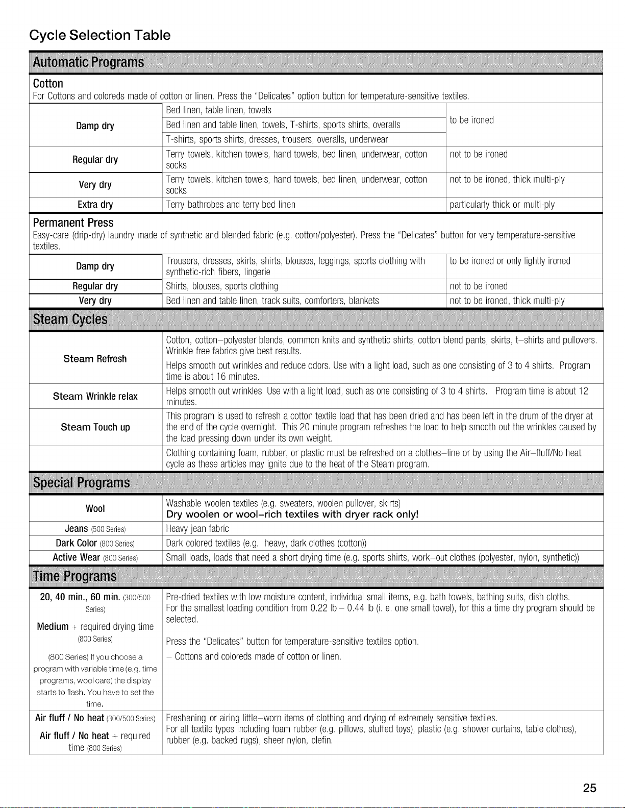
Cycle Selection Table ...............................................................................
Automatic cycles ...................................................................................
Steam cycles ......................................................................................
Special cycles .....................................................................................
Time cycles .......................................................................................
Additional Options on LCD Menu .....................................................................
Operation ...........................................................................................
Using the dryer ....................................................................................
Cleaning the lint filter ................................................................................
Using the dryer rack (Option) .........................................................................
Cleaning and care ...................................................................................
Cleaning the dryer ..................................................................................
Cleaning the exhaust duct ...........................................................................
Cleaning the moisture sensor ........................................................................
Cleaning the lint filter housing ........................................................................
Cleaning the Steam nozzle ..........................................................................
Change the light bulb ...............................................................................
Troubleshooting .....................................................................................
SERVICE and REPAIR ..............................................................................
STATEMENT OF LIMITED PRODUCT WARRANTY ......................................................
4
5
6
7
7
7
7
8
8
8
9
12
15
15
16
19
2O
21
21
22
22
22
22
22
23
23
23
24
25
25
25
25
25
25
27
27
28
29
30
3O
3O
3O
3O
3O
3O
31
33
34
3
Congratulations!
Your new clothes dryer is a modern,
high quality domestic appliance.
This dryer complies with: ANSI Z21.5.1/
CSA 7.1 Clothes Dryers Vol. 1.
A distinctive feature of your dryer is low
energy consumption.
An easy operation philosophy, a variety
of customized drying programs, and a
solid touch and feel make this
appliance a user-friendly assistant in
your household.
Bosch dryers offer the following
standard features:
- High-efficiency precision drying
system
Large stainless steel drum with a
capacity of up to 17.6 Ibs (8 kg)
Large port hole (16"/406 mm), and
door interlock with automatic drum
stop function
Exceptionally quiet operation
Sensor-controlled auto cycles
Timed cycles
300 and 500 Series Dryer: 20, 40
and 60 minute cycles
800 Series Dryer: 10 to
150 minutes (in increments of 10
minutes)
Wrinkle Block® feature tumbles
clothes periodically for up to one
hour following drying to help
decrease wrinkling
Each dryer which leaves our factory
has undergone a thorough
performance test and is in full working
condition. If you have any questions,
especially concerning installation of the
dryer - our customer service team will
be happy to assist you.
Further information and a selection of
our products can be found on our web
site:
www.bosch-home.com/us
Information
Models Covered by this User
Manual
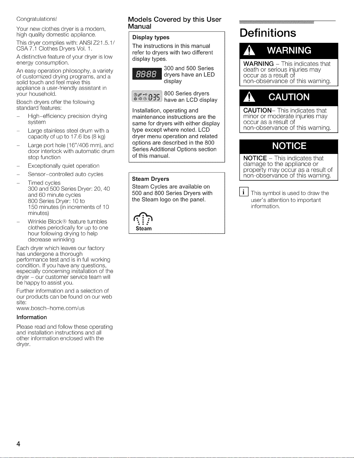
Display types
The instructions in this manual
refer to dryers with two different
display types.
300 and 500 Series
dryers have an LED
display
800 Series dryers
have an LCD display
Installation, operating and
maintenance instructions are the
same for dryers with either display
type except where noted. LCD
dryer menu operation and related
options are described in the 800
Series Additional Options section
of this manual.
Steam Dryers
Steam Cycles are available on
500 and 800 Series Dryers with
the Steam logo on the panel.
Steam
Definitions
WARNING - This indicates that
death or serious injuries may
occur as a result of
non-observance of this warning.
CAUTION- This indicates that
minor or moderate injuries may
occur as a result of
non-observance of this warning.
NOTICE - This indicates that
damage to the appliance or
property may occur as a result of
non-observance of this warning.
D This symbol is used to draw the
user's attention to important
information.
Please read and follow these operating
and installation instructions and all
other information enclosed with the
dryer.
4
,/k IMPORTANT SAFETY INSTRUCTIONS
The warnings and safety
instructions in this manual can not
cover all possible risks, conditions
and situations that may arise. Use
common sense and exercise
caution when installing, maintaining
and operating this or any other
appliance.
To reduce the risk of fire, electric
shock, serious injury or death to
persons and/or damage when
using your dryer, follow basic
precautions, _ncluding the
following.
1. Read all instructions before using
the dryer. Bosch dryers are
provided with Operating, Care and
Installation Instructions.
2. Do not dry articles that have been
previously cleaned, washed,
soaked or spotted with gasoline,
dry cleaning solvents, or other
flammable or explosive
substances as they give off vapors
that could ignite or explode.
To reduce the risk of fire, clothes,
cleaning rags, mop heads and the
like which have traces of any
flammable substance, such as
vegetable oil, cooking oil,
petroleum-based oils or distillates,
waxes, fats, etc., must not be
placed in the dryer. These items
may contain some flammable
substance(s), even after washing,
which may smoke or catch fire by
themselves.
Do not place items exposed to
cooking oils in your dryer. Items
contaminated with cooking oils
may contribute to a chemical
reaction that could cause a
laundry load to catch fire.
3. The dryer must only be used for its
intended purpose.
4. When children become old
enough to operate the appliance, it
is the responsibility of the parents
or legal guardians to ensure that
they are instructed insafe
practices by qualified persons.
5. Do not allow children to play on or
in the appliance at any time;
severe injury or death could
result. Children should be kept a
safe distance away from
appliances at all times. Children
should only be permitted within an
appliance's vicinity if under close,
constant adult supervision.
6. Do not allow children's toys, or
other items that might encourage
children to climb on the dryer, to
be stored on or in the dryer or on
shelves or in cabinets or other
storage areas adjacent to the
dryer.
7. Do not sit or stand on the top of
the dryer.
8. Do not allow anyone to climb, lean
or hang on any part of the dryer
including any protruding
components such as the
appliance door or a pullout shelf.
9. To reduce the risk of poisoning or
chemical burns, keep all cleaning
products out of the reach of
children.
10.
Store all laundry chemicals and
aids in a cool dry place according
to the manufacturer's instructions.
Make sure children cannot reach
them. Gasoline, combustible
materials and materials that
produce flammable vapors,
flammable liquids, and substances
that pose a fire hazard must not be
stored near the dryer.
11.
Keep pets away from the dryer.
12.
BEFORE THE APPLIANCE IS
REMOVED FROM SERVICE OR
DISCARDED, REMOVE THE
DOOR TO THE DRYING
COMPARTMENT.
Do not reach into the appliance if
the drum is rotating.
Do not install or store this
appliance where it will be exposed
to the weather or the elements,
such as water/moisture, dirt,
corrosive/salt air, and excessive
cold.
15. Do not tamper with the controls.
16. Do not repair or replace any part of
the appliance or attempt any
service unless specifically
recommended in the
user-maintenance instructions or
in published user repair
instructions that you understand
and have the skills to carry out.
17. Do not use fabric softeners or
products to eliminate static unless
recommended by the fabric
manufacturer.
18. Do not use heat to dry articles
containing foam rubber (may be
labeled latex foam) or similarly
textured rubber-like materials.
Foam rubber materials can ignite
by spontaneous combustion.
19.
Do not dry articles containing
spunbonded olefin. Spunbonded
olefin can melt and can ignite by
spontaneous combustion.
20.
Check the lint screen before each
laundry load and clean as needed.
Excess lint buildup can damage
the dryer and create a potential
fire hazard.
21.
Keep area around the exhaust
opening and adjacent surrounding
areas free from the accumulation
of lint, dust and dirt. An obstructed
port might reduce the airflow and
cause overheating.
22. The interior of the machine and
exhaust duct should be cleaned
periodically by qualified service
personnel.
23. Removing any panel or cover,
including the light cover, may
expose live electrical circuits.
Removing any panel, including the
round service panel in the front,
can also expose sharp edges and
points as well as hot surfaces.
Always unplug the dryer from the
electrical supply before attempting
any service. Disconnect the power
cord by grasping the plug, not the
cord.
24. To avoid fire hazards, do not use
an extension cord, an adapter, or
any other non-manufacturer
supplied electrical connector or
cord, to connect the dryer to the
electrical supply.
25. Always check clothing pockets
and shake out all laundry items
5
before placing into dryer;
inappropriate objects can damage
the dryer and certain items like
cigarette lighters can pose a fire
hazard.
26. To reduce the risk of fire and
electrical shock hazards, do not
use the dryer ifthe power cord is
frayed or damaged, or if the plug is
loose.
27. Do not operate the dryer ifany
guards and/or panels have been
removed or if any parts are missing
or broken.
28. Do not bypass any safety devices.
29. Do not use a plastic or non-metal
flexible duct with this dryer. Plastic
or non-metal flexible duct isa
potential fire hazard.
30. Do not operate this dryer until you
are sure that the dryer has been
installed according to the
INSTALLATION INSTRUCTIONS
and that installation and electrical
grounding are in compliance with
all local regulations and/or other
applicable regulations and
requirements.
31. Failure to install, maintain and/or
operate the dryer according to
the manufacturer's instructions
may result in injury and/or
damage.
32. To avoid floor damage and mold
growth, do not let spills or
splashout to cause standing water
around or under the appliance.
33. No other fuel-burning appliances
shall be installed in the same
closet as the dryer.
34. Make sure that all water
connections to the dryer have a
shut-off valve that is readily
accessible. Close the appliance
water shut-off valve(s) at the end
of each day of use.
35. Check the fill hose connections on
a regular basis to ensure that they
are tight and not leaking.
Notes:
A
The IMPORTANT
SAFEGUARDS and
WARNINGS presented in this
manual do not cover all
possible conditions that may
Occur.
Common sense, caution and
care must be exercised when
installing, maintaining or
operating the dryer.
B
Always contact your dealer,
distributor, service agent or
the manufacturer about any
problems or conditions that
you do not understand.
C
Follow the Safety Information
provided in the
INSTALLATION
INSTRUCTIONS and the
OPERATING
INSTRUCTIONS.
GROUNDING
INSTRUCTIONS
This appliance must be grounded. In
the event of malfunction or breakdown,
grounding will reduce the risk of electric
shock by providing a path of least
resistance for the electric current.
For the State of Massachusetts In-
stallations:
1. Installation must be performed by a li-
censed plumber or gas fitter licensed by
the state, province or region where this
appliance is being installed.
2. Shut-off valve must be a "T" handle
gas cock.
3. Flexible gas connector must not be
longer than 36 inches (0.91 m).
Improper connection of the
equipment grounding conductor
can result in a risk of electric
shock.
Check with a qualified electrician
or service person if you are in
doubt as to whether the dryer is
B_Doperlygrounded.
NOT modify the plug
provided with the appliance.
If it will not fit the outlet, have
a proper outlet installed by
a qualified electrician.
KEEP THESE
INSTRUCTIONS FOR
FUTURE REFERENCE.
In case of change of ownership, this
manual should be conveyed with the
dryer.
SAVE THESE
INSTRUCTIONS
INSTALLATION INSTRUCTIONS
Introduction
Read these installation instructions
completely and carefully. They will save
you time and effort and help to ensure
optimum dryer performance. Be sure to
observe all listed warnings and
cautions.
WARNING - Risk of Fire.
- Clothes dryer installation must be
performed by a qualified installer.
- Install the clothes dryer according
to the manufacturer's instructions
and local codes.
- Do not install a clothes dryer with
flexible plastic venting materials. If
flexible metal (foiltype) duct is
installed, it must be of a specific
type identified by the appliance
manufacturer as suitable for
clothes dryers. Flexible venting
materials are known to collapse,
be easily crushed and trap lint.
These conditions will obstruct
clothes dryer airflow and increase
the risk of fire.
- To reduce the risk of severe injury
or death, follow all installation
instructions.
- SAVETHESE INSTRUCTIONS.
Inaddition to these instructions the
dryer must be installed in accordance
with all local codes or, in the absence
of a local code:
In the U.S.A., in accordance with
the National Electric Code,
ANSI/NFPA70 -latest
edition/State and Municipal codes
and/or local codes.
- In Canada, in accordance with the
Canadian Electric Code C22.1 -
latest edition/Provincial and
Municipal codes and/or local
codes.
The gas installation must conform with
local codes, or in absence of local
codes, with the National Fuel Gas
Code, ANSI Z223.1/NFPA 54 or the
Canadian Natural Gas and Propane
Installation Code CAN/CSA-B149.1
Note:
This gas dryer has been UL and C-UL
listed for safe operation up to a height
of 7,700 ft. without any modifications to
components for natural gas.
Information concerning
waste disposal
Disposal of the packaging
Keep children away from the
shipping carton andpackaging
components to avoidrisk of
suffocation.
All packaging materials are
environmentally friendly and can be
reused. Please dispose of packaging in
an environmentally friendly manner.
Please ask your dealer or inquire at
your local authority about the best
means of disposal.
Disposal of the old appliance
If the appliance is no longer
usable, pull out main plug, cut off
power cord and discard with
main plug. To prevent children
from locking themselves in the
appliance, remove the door.
Old appliances are not worthless
rubbish! Valuable raw materials can be
reclaimed from environmentally friendly
recycling.
Please ask your dealer or inquire at
your local authority about the best
means of disposal.
Before installing the dryer
Before installing the dryer to a
previously used ductwork system,
make sure the system is clean.
Professional ductwork cleaning is
recommended annually and also when
attaching your dryer to a previously
used ductwork system.
Maintaining clean ductwork will reduce
drying time and will improve drying
performance.
Unpacking the appliance
The dryer is very heavy, Do not
lift it by yourself. Do not lift the
appliance by projecting
components (e.g. door) - due to
risk of breakage.
Remove the appliance
packaging carefully to prevent
damage to appliance surfaces
and adjacent areas.
Check the dryer for transportation
damage. Do not install a dryer which is
visibly damaged. If in doubt, contact
your dealer.
Supplied components
After removing the packaging,
immediately remove any objects
from the drum.
7
Installation location
DO NOT install the dryer:
- outdoors
- in an environment with dripping
water,
- near flammable materials,
- in rooms which are at risk of frost,
- in rooms which may contain gas
or other fuels,
- in cupboards with Iockable doors
or in alcoves.
- with other fuel-burning appliances
in the same closet.
The installation room must be well
ventilated, otherwise the dryer will
operate below optimum performance.
Do not operate the dryer at
temperatures above 104°F (40°C) or
below 41 °F (5°C). Low temperatures
affect the automatic program sequence
and may prolong the drying times.
The installation surface for the dryer
must be clean, level and firm. Do not
install the appliance on carpets!
Compensate for uneven floors with the
height-adjustable feet.
The size of the installation area
depends on the dimensions of the
dryer. Ensure that there is adequate
room for the swivel range of the door!
If installed in a garage, the dryer
must be installed on a substantial
platform at least 18 inches (46 cm)
above the floor to reduce the
likelihood of igniting flammable
vapors and be located or protected
so it cannot be damaged by a
moving vehicle.
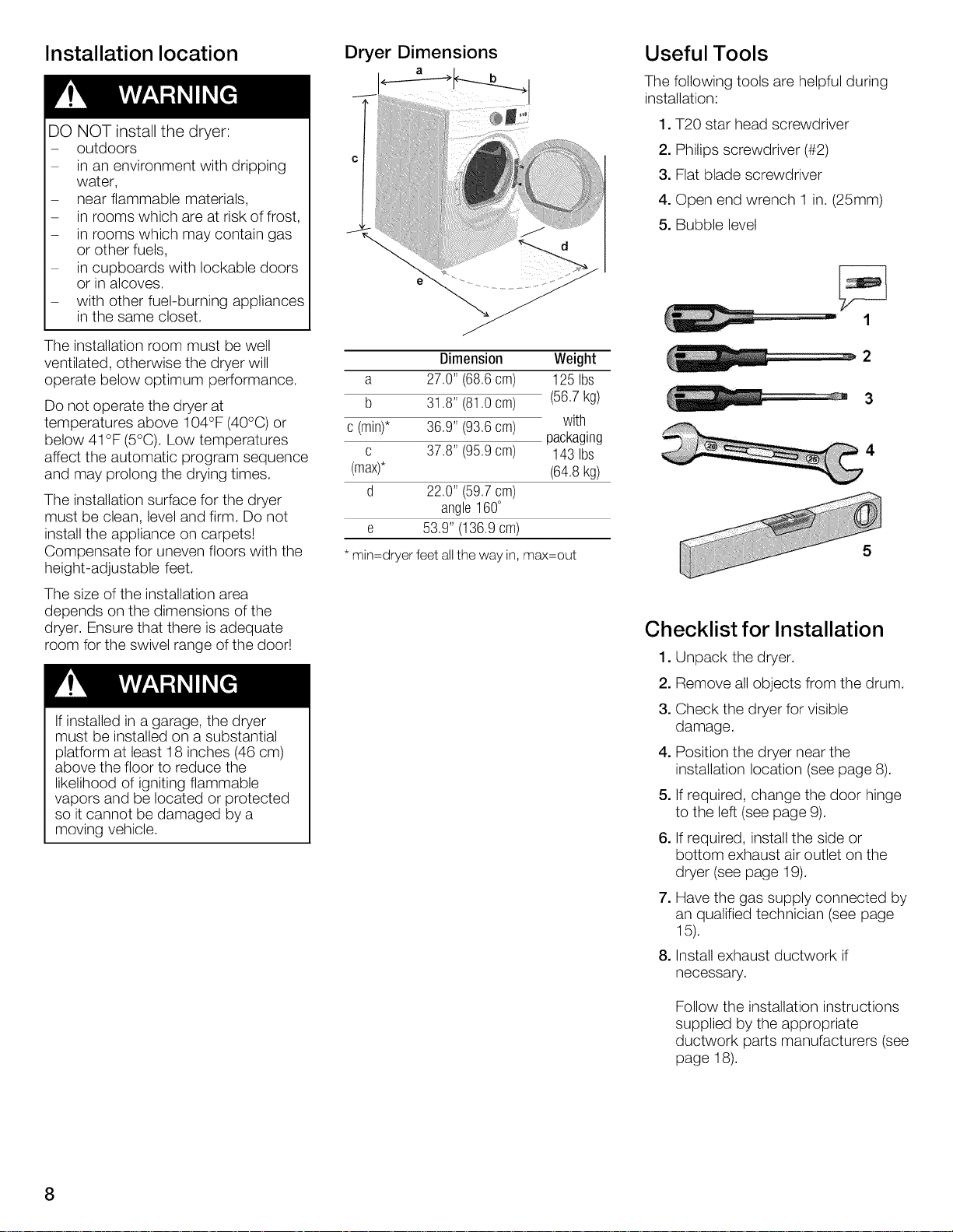
Dryer Dimensions
J
Dimension Weight
a 27,0" (68,6cm) 125Ibs
b 31,8" (81,0cm) (56,7kg)
c (min)* 36,9" (93,6cm) with
packaging
c 37,8" (95,9cm) 143Ibs
(max)* (64,8kg)
d 22,0" (59,7cm)
angle160°
e 53,9"(136,9cm)
* rain=dryer feet all the way in, max=out
Useful Tools
The following tools are helpful during
installation:
1. T20 star head screwdriver
2. Philips screwdriver (#2)
3. Flat blade screwdriver
4. Open end wrench 1 in. (25ram)
5. Bubble level
1
2
4
5
Checklist for Installation
1. Unpack the dryer.
2. Remove all objects from the drum.
3. Check the dryer for visible
damage.
4. Position the dryer near the
installation location (see page 8).
5. If required, change the door hinge
to the left (see page 9).
6. If required, install the side or
bottom exhaust air outlet on the
dryer (see page 19).
7. Have the gas supply connected by
an qualified technician (see page
15).
8. Install exhaust ductwork if
necessary.
Follow the installation instructions
supplied by the appropriate
ductwork parts manufacturers (see
page 18).
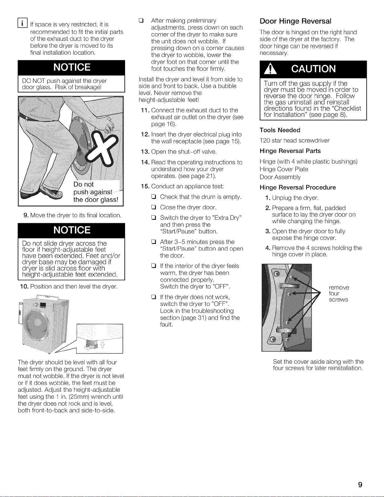
[_lf spaceisveryrestricted,itis
recommendedtofittheinitialparts
oftheexhaustducttothedryer
beforethedryerismovedtoits
finalinstallationlocation.
DONOTpushagainstthedryer
doorglass.Riskofbreakage!
De not
push against
the d0or glass!
9. Move the dryer to its final location.
Do not slide dryer across the
floor if height-adjustable feet
have been extended. Feet and/or
dryer base may be damaged if
dryer is slid across floor with
height-adjustable feet extended.
10. Position and then level the dryer.
!!iii !i!ii i!i!ii i@iiiilmiliiiiiiiii!@
tl
E3
After making preliminary
adjustments, press down on each
corner of the dryer to make sure
the unit does not wobble. If
pressing down on a corner causes
the dryer to wobble, lower the
dryer foot on that corner until the
foot touches the floor firmly.
Install the dryer and level it from side to
side and front to back. Use a bubble
level. Never remove the
height-adjustable feet!
11. Connect the exhaust duct to the
exhaust air outlet on the dryer (see
page 16).
12.
Insert the dryer electrical plug into
the wall receptacle (see page 15).
13.
Open the shut-off valve.
14.
Read the operating instructions to
understand how your dryer
operates. (see page 21).
15.
Conduct an appliance test:
Check that the drum is empty.
Close the dryer door.
Switch the dryer to "Extra Dry"
and then press the
"Start/Pause" button.
After 3-5 minutes press the
"Start/Pause" button and open
the door.
E3
If the interior of the dryer feels
warm, the dryer has been
connected properly.
Switch the dryer to "OFF".
E3
If the dryer does not work,
switch the dryer to "OFF".
Look in the troubleshooting
section (page 31) and find the
fault.
Door Hinge Reversal
The door is hinged on the right hand
side of the dryer at the factory. The
door hinge can be reversed if
necessary.
Turn off the gas supply if the
dryer must be moved Lnorder to
reverse the door hinge. Follow
the gas uninstall andreinstall
directions found in the "Checklist
for Installation" (see page 8).
Tools Needed
T20 star head screwdriver
Hinge Reversal Parts
Hinge (with 4 white plastic bushings)
Hinge Cover Plate
Door Assembly
Hinge Reversal Procedure
1. Unplug the dryer.
2. Prepare a firm, flat, padded
surface to laythe dryer door on
while changing the hinge.
3. Open the dryer door to fully
expose the hinge cover.
4. Remove the 4 screws holding the
hinge cover in place.
remove
four
screws
The dryer should be level with all four
feet firmly on the ground. The dryer
must not wobble. Ifthe dryer is not level
or if it does wobble, the feet must be
adjusted. Adjust the height-adjustable
feet using the 1 in. (25mm) wrench until
the dryer does not rock and is level,
both front-to-back and side-to-side.
Set the cover aside along with the
four screws for later reinstallation.
9
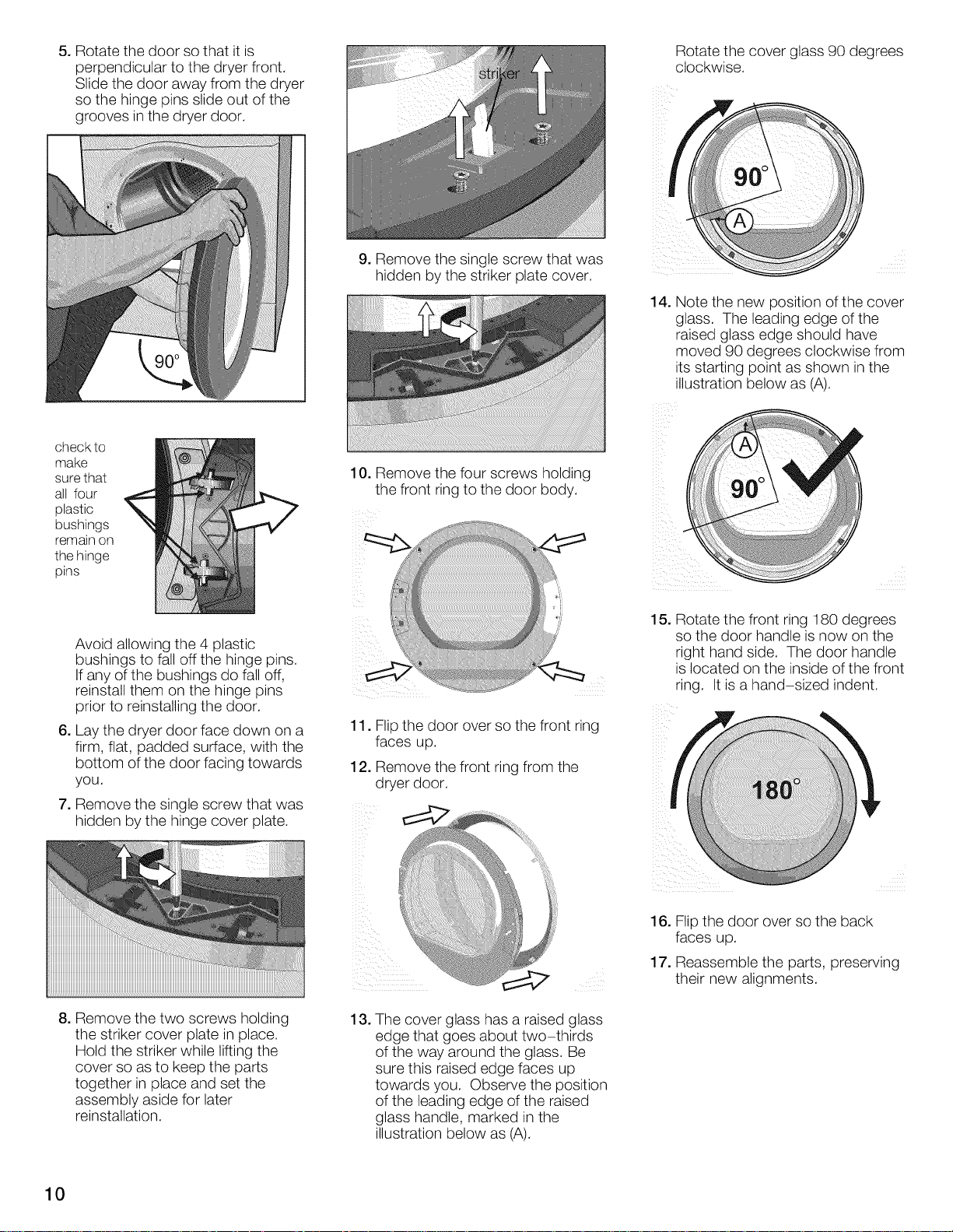
5. Rotate the door so that it is
perpendicular to the dryer front.
Slide the door away from the dryer
so the hinge pins slide out of the
grooves inthe dryer door.
check to
make
sure that
all four
plastic
bushings
remain on
the hinge
pins
Rotate the cover glass 90 degrees
clockwise.
9. Remove the single screw that was
hidden by the striker plate cover.
14. Note the new position of the cover
glass. The leading edge of the
raised glass edge should have
moved 90 degrees clockwise from
its starting point as shown in the
illustration below as (A).
10. Remove the four screws holding
the front ring to the door body.
Avoid allowing the 4 plastic
bushings to fall off the hinge pins.
If any of the bushings do fall off,
reinstall them on the hinge pins
prior to reinstalling the door.
6. Lay the dryer door face down on a
firm, flat, padded surface, with the
bottom of the door facing towards
you.
7. Remove the single screw that was
hidden by the hinge cover plate.
8. Remove the two screws holding
the striker cover plate in place.
Hold the striker while lifting the
cover so as to keep the parts
together in place and set the
assembly aside for later
reinstallation.
15. Rotate the front ring 180 degrees
so the door handle is now on the
right hand side. The door handle
is located on the inside of the front
ring. It is a hand-sized indent.
11. Flip the door over so the front ring
faces up.
12. Remove the front ring from the
dryer door.
16. Flipthe door over so the back
faces up.
17. Reassemble the parts, preserving
their new alignments.
13. The cover glass has a raised glass
edge that goes about two-thirds
of the way around the glass. Be
sure this raised edge faces up
towards you. Observe the position
of the leading edge of the raised
glass handle, marked inthe
illustration below as (A).
10
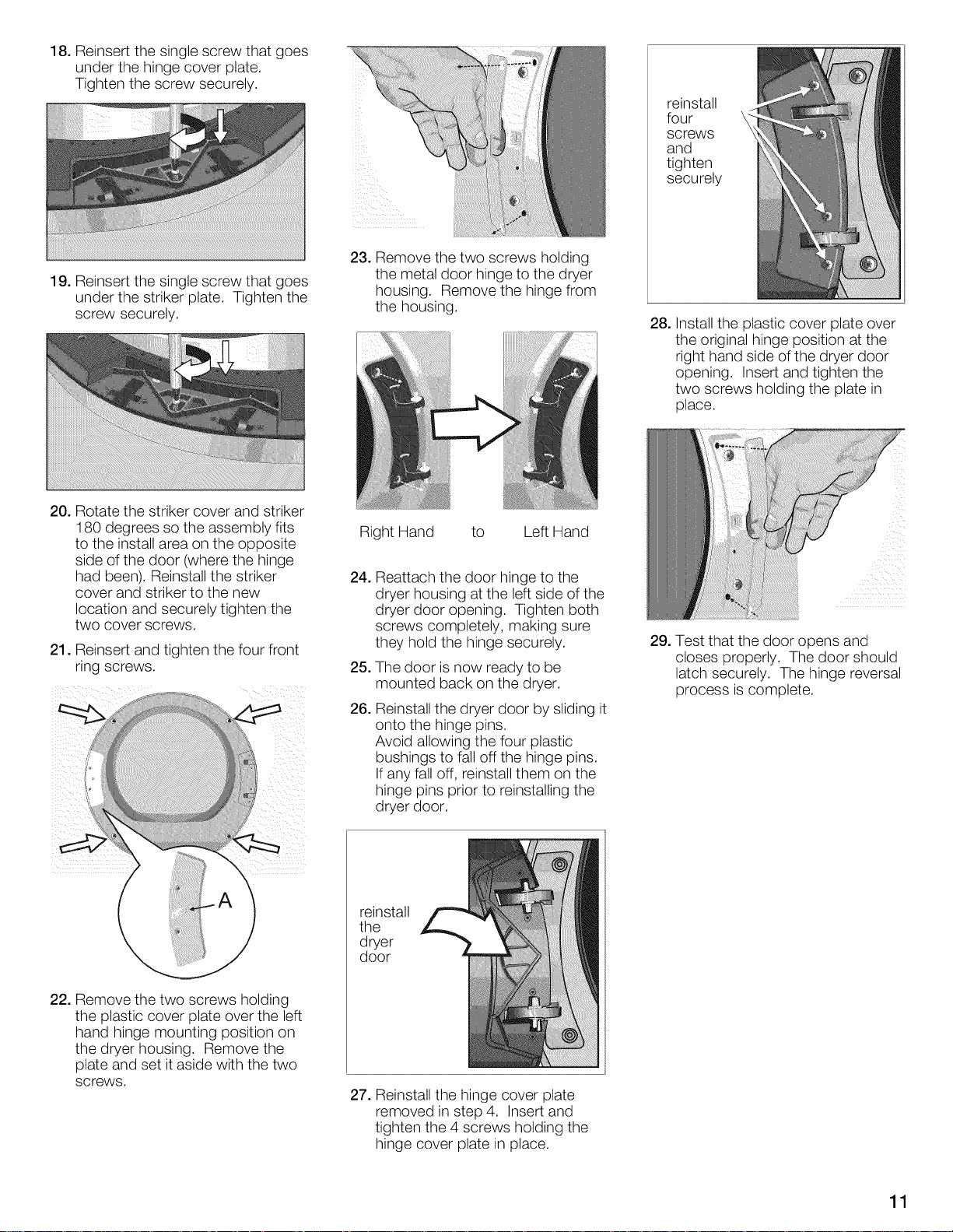
18. Reinsert the single screw that goes
under the hinge cover plate.
Tighten the screw securely.
19. Reinsert the single screw that goes
under the striker plate. Tighten the
screw securely.
reinstall
four
screws
and
tighten
securely
23. Remove the two screws holding
the metal door hinge to the dryer
housing. Remove the hinge from
the housing.
28. Install the plastic cover plate over
the original hinge position at the
right hand side of the dryer door
opening. Insert and tighten the
two screws holding the plate in
place.
20. Rotate the striker cover and striker
180 degrees so the assembly fits
to the install area on the opposite
side of the door (where the hinge
had been). Reinstall the striker
cover and striker to the new
location and securely tighten the
two cover screws.
21. Reinsert and tighten the four front
ring screws.
Right Hand to Left Hand
24.
Reattach the door hinge to the
dryer housing at the left side of the
dryer door opening. Tighten both
screws completely, making sure
they hold the hinge securely.
The door is now ready to be
mounted back on the dryer.
Reinstall the dryer door by sliding it
onto the hinge pins.
Avoid allowing the four plastic
bushings to fall off the hinge pins.
If any fall off, reinstall them on the
hinge pins prior to reinstalling the
dryer door.
reinstall
the
dryer
door
29. Test that the door opens and
closes properly. The door should
latch securely. The hinge reversal
process is complete.
22. Remove the two screws holding
the plastic cover plate over the left
hand hinge mounting position on
the dryer housing. Remove the
plate and set it aside with the two
screws.
27. Reinstall the hinge cover plate
removed in step 4. Insert and
tighten the 4 screws holding the
hinge cover plate in place.
11
Minimum Distances
Important information concerning
minimum distances:
- Depending on the location of the
exhaust air connection, an
additional minimum distance of
51/2inch (14 cm) must be provided
on this side, the side the
connection is on, for
ducts/brackets (see page 19).
- Benefits of maintaining greater
distance (clearances) than the
minimum shown include:
* more air cools the dryer, keeps
the dryer from overheating, and
improves drying performance.
* reduction of the risk of mold
formation behind the appliance.
* reduced noise transmission
* facilitation of installation and
service.
- If the dryer is installed in a small
room, the doors of the room must
be fitted with vents of the specified
minimum size. Refer to the
following illustrations of enclosed
installations for additional
information.
- Allow additional clearance for
door, wall and window molding
where necessary.
Installation Types
Observe the following minimum
clearances between the dryer and
adjacent surfaces for all installation
types.
Minimum Installation Clearances
A Sides 0.25in.(6.4mm)
B Top 0.25in.(6.4mm)
C Rear* 5.25in.(13.4cm)
D Front 0.50in,(12.8mm)
* as closetowall asventingorwater
connectionwillallow,Ifinstalledwitha
washer,the largerrearclearancefor dryer
ventingis requiredforthe laundrypair,
Units are designed so that the
dryer can be stacked on top of the
washer using one of the stacking
kits shown on page 20.
Units are designed to allow for
under-counter installation See
required dimensions in under-
counter installation section on
page 13.
Height measurements shown in this
section are with the dryer feet at
minimum extension (turned in all the
way up against the base of the dryer).
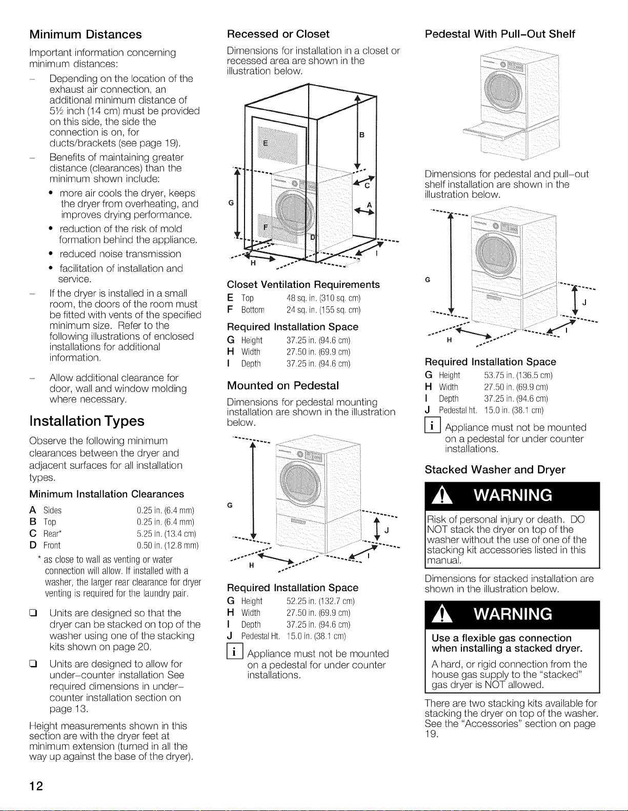
Recessed or Closet
Dimensions for installation in a closet or
recessed area are shown in the
illustration below.
Closet Ventilation Requirements
E Top 48sq.in.(310sq.cm)
F Bottom 24sq, in,(155sq,cm)
Required Installation Space
G Height 37.25in.(94.6cm)
H Width 27.50in,(69.9cm)
I Depth 37.25in. (94.6cm)
Mounted on Pedestal
Dimensions for pedestal mounting
installation are shown in the illustration
below.
i ¸ ii i ( J
I
Required Installation Space
G Height 52.25in.(132.7cm)
H Width 27.50in.(69.9cm)
I Depth 37.25in,(94,6cm)
J PedestalHt, 15,0in.(38.1cm)
D Appliance must not be mounted
on a pedestal for under counter
installations.
Pedestal With Pull-Out Shelf
Dimensions for pedestal and 3ull-out
shelf installation are shown in the
illustration below.
G
J
Required Installation Space
G Height 53.75in.(136.5cm)
H Width 27.50in,(69.9cm)
I Depth 37.25in.(94.6cm)
J Pedestalht,15,0in.(38.1cm)
D Appliance must not be mounted
on a pedestal for under counter
installations.
Stacked Washer and Dryer
Risk of personal injury or death. DO
NOT stack the dryer on top of the
washer without the use of one of the
stacking kit accessories listed in this
manual.
Dimensions for stacked installation are
shown in the illustration below.
Use a flexible gas connection
when installing a stacked dryer.
A hard, or rigid connection from the
house gas supply to the "stacked"
gas dryer is NOT allowed.
There are two stacking kits available for
stacking the dryer on top of the washer.
See the "Accessories" section on page
19.
12
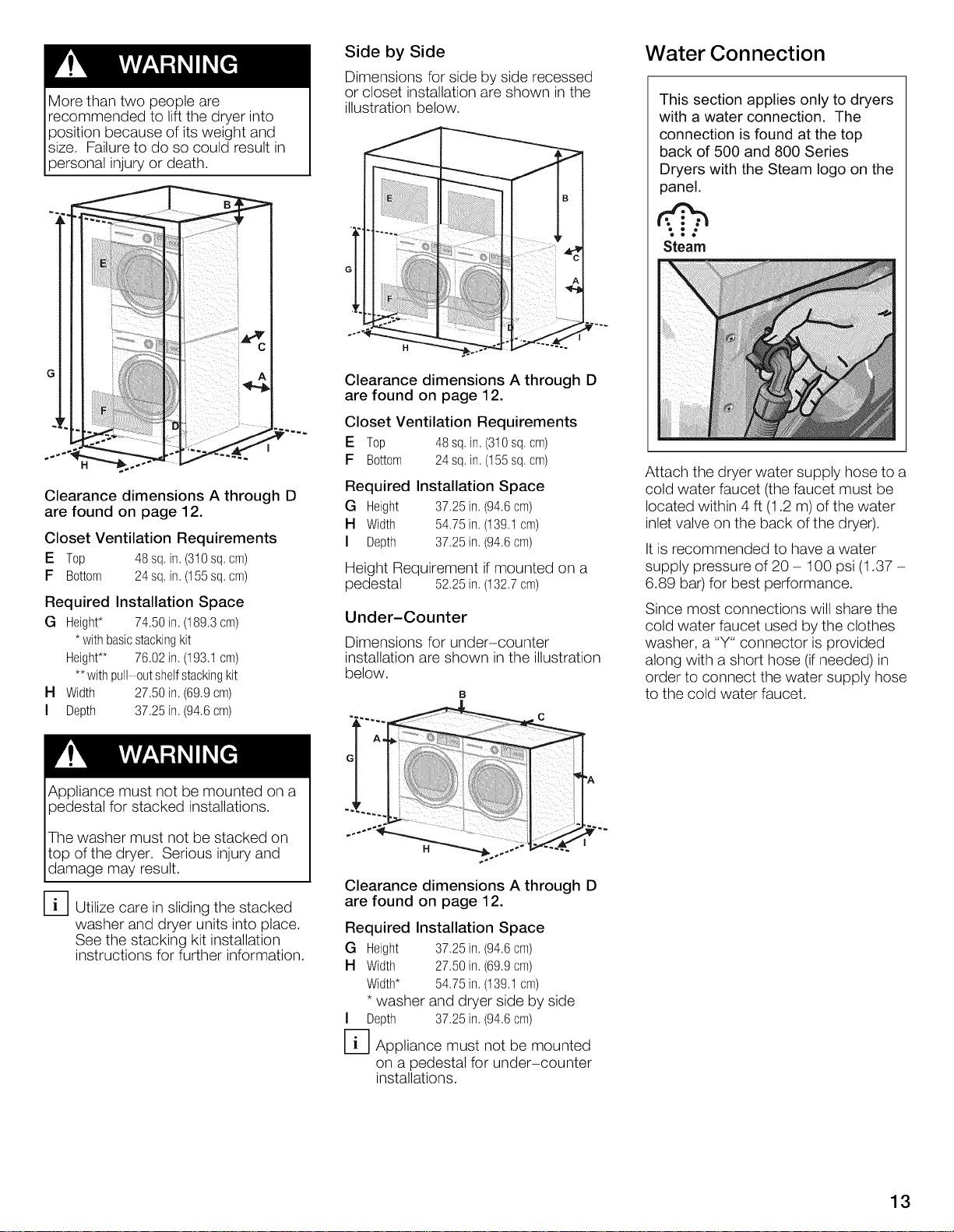
More than two people are
recommended to lift the dryer into
position because of its weight and
size. Failure to do so could result in
persona njury or death.
Clearance dimensions A through D
are found on page 12.
Closet Ventilation Requirements
E Top 48 sq.in.(310sq.cm)
F Bottom 24 sq,in, (155sq,cm)
Required Installation Space
G Height* 74.50 in. (189,3cm)
* withbasicstackingkit
Height** 76.02in,(193.1cm)
**withpull-0ut shelfstackingkit
H Width 27.50 in, (69.9cm)
I Depth 37.25in. (94.6cm)
Side by Side
Dimensions for side by side recessed
or closet installation are shown in the
illustration below.
Clearance dimensions A through D
are found on page 12.
Closet Ventilation Requirements
E Top 48sq.in.(310sq.cm)
F Bottom 24sq,in, (155sq,cm)
Required Installation Space
G Height 37.25in.(94.6cm)
H Width 54.75in,(t39,t cm)
I Depth 37.25in. (94.6cm)
Height Requirement if mounted on a
pedestal 52.25in.(132.7cm)
Under-Counter
Dimensions for under-counter
installation are shown in the illustration
below.
Water Connection
This section applies only to dryers
with a water connection. The
connection is found at the top
back of 500 and 800 Series
Dryers with the Steam logo on the
panel,
Steam
Attach the dryer water supply hose to a
cold water faucet (the faucet must be
located within 4 ft (1.2 m) of the water
inlet valve on the back of the dryer).
It is recommended to have a water
supply pressure of 20 - 100 psi (1.37 -
6.89 bar) for best performance.
Since most connections will share the
cold water faucet used by the clothes
washer, a "Y" connector is provided
along with a short hose (if needed) in
order to connect the water supply hose
to the cold water faucet.
Appliance must not be mounted on a
pedestal for stacked installations.
The washer must not be stacked on
top of the dryer. Serious injury and
damage may resut.
F_ Utilize care in sliding the stacked
washer and dryer units into place.
See the stacking kit installation
instructions for further information.
Clearance dimensions A through D
are found on page 12.
Required Installation Space
G Height 37.25in.(94.6cm)
H Width 27.50in.(69.9cm)
Width* 54.75in.(139.tcm)
* washer and dryer side by side
I Depth 37.25in.(94.6cm)
D Appliance must not be mounted
on a pedestal for under-counter
installations.
13
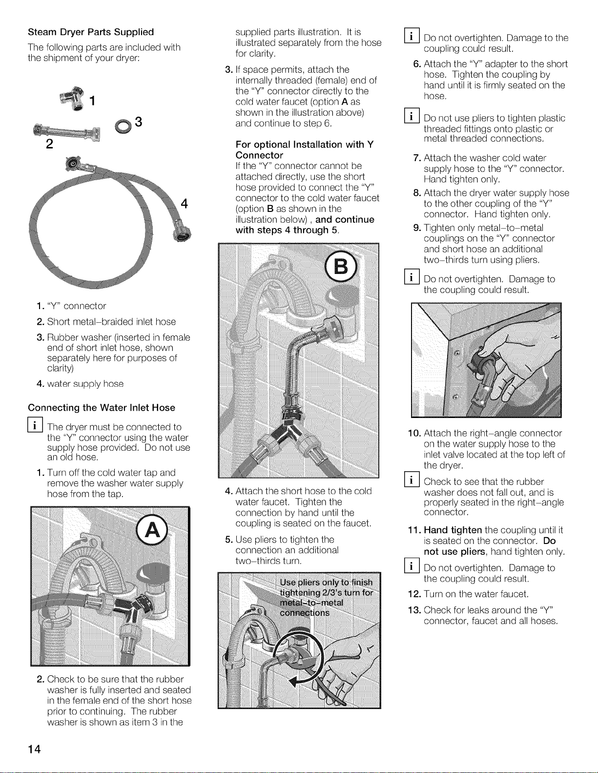
Steam Dryer Parts Supplied
The following parts are included with
the shipment of your dryer:
0 3
2
1. "Y" connector
2. Short metal-braided inlet hose
3. Rubber washer (inserted in female
end of short inlet hose, shown
separately here for purposes of
clarity)
4. water supply hose
supplied parts illustration. It is
illustrated separately from the hose
for clarity.
,
If space permits, attach the
internally threaded (female) end of
the "Y" connector directly to the
cold water faucet (option A as
shown in the illustration above)
and continue to step 6.
For optional Installation with Y
Connector
If the "Y" connector cannot be
attached directly, use the short
hose provided to connect the "Y"
4
connector to the cold water faucet
(option B as shown in the
illustration below), and continue
with steps 4 through 5.
D Do not overtighten. Damage to the
coupling could result.
6. Attach the "Y" adapter to the short
hose. Tighten the coupling by
hand until it isfirmly seated on the
hose.
D Do not use pliers to tighten plastic
threaded fittings onto plastic or
metal threaded connections.
7. Attach the washer cold water
supply hose to the "Y" connector.
Hand tighten only.
8. Attach the dryer water supply hose
to the other coupling of the "Y"
connector. Hand tighten only.
9. Tighten only metal-to-metal
couplings on the "Y" connector
and short hose an additional
two-thirds turn using pliers.
D Do not overtighten. Damage to
the coupling could result.
Connecting the Water Inlet Hose
I-_1 The dryer must be connected to
the "Y" connector using the water
supply hose provided. Do not use
an old hose.
1. Turn off the cold water tap and
remove the washer water supply
hose from the tap.
2. Check to be sure that the rubber
washer is fully inserted and seated
in the female end of the short hose
prior to continuing. The rubber
washer is shown as item 3 in the
4. Attach the short hose to the cold
water faucet. Tighten the
connection by hand until the
coupling is seated on the faucet.
5. Use pliers to tighten the
connection an additional
two-thirds turn.
10. Attach the right-angle connector
on the water supply hose to the
inlet valve located at the top left of
the dryer.
D Check to see that the rubber
washer does not fall out, and is
properly seated in the right-angle
connector.
11. Hand tighten the coupling until it
is seated on the connector. Do
not use pliers, hand tighten only.
D Do not overtighten. Damage to
the coupling could result.
12. Turn on the water faucet.
13. Check for leaks around the "Y"
connector, faucet and all hoses.
14
Electrical Connection
GROUNDING INSTRUCTIONS
The dryer must only be connected
to an individual branch circuit via a
socket which has been properly
installed and grounded.
The household electrical voltage must
correspond to the voltage specification
on the dryer (rating plate).
You will find the rating plate on the
inside of the front panel.
Connection specifications as well as
the electrical requirements are
stipulated on the appliance nameplate.
Make sure that:
- the power cord plug fits into the
socket.
- the power cord is acceptable for
use in this application, if replaced.
- the grounding system is properly
installed.
The power cord may be replaced by a
qualified technician or a licensed
electrician only.
Replacement power cords are available
from Customer Service (see page 33).
Volts Hertz Amperes Watts
110 120 60 9 1080
Gas connection
Explosion hazard!
Use a new AGA or CSA approved
gas supply line.
Install a shut-off valve.
Securely tighten all gas
connections.
Do not crush or kink the gas line.
Have a qualified person make sure
gas pressure does not exceed
14 in. W.C./3.49 kPa/0.506 psig.
(Natural Gas and Propane).
Examples of a qualified person
include:
- licensed heating personnel,
- authorized gas supplier personnel
- authorized service personnel.
Failure to do so can result in
explosion or fire.
Risk of death or injury!
All gas line connections must be
tested for leaks prior to appliance
operation. Apply soapy water to gas
line connections and check for
formation of new bubbles. Bubbles
indicate a leak!
When installing the gas supply to the
gas dryer inlet pipe, do not exceed 26
ft-lb (35 Nm).
Never use an open flame to test for
gas leaks.
Gas type
This dryer when equipped for use with
NATURAL GAS will employ an orifice
size 46 and will have a gas outlet
pressure of 3.5 in. W.C.
Your dryer must have the correct valve
for the type of gas in your home. Valve
information is located on the rating
plate behind the door below the port
hole.
If the rating-plate information does not
agree with the type of gas available,
contact your dealer or our customer
service team (see page 33).
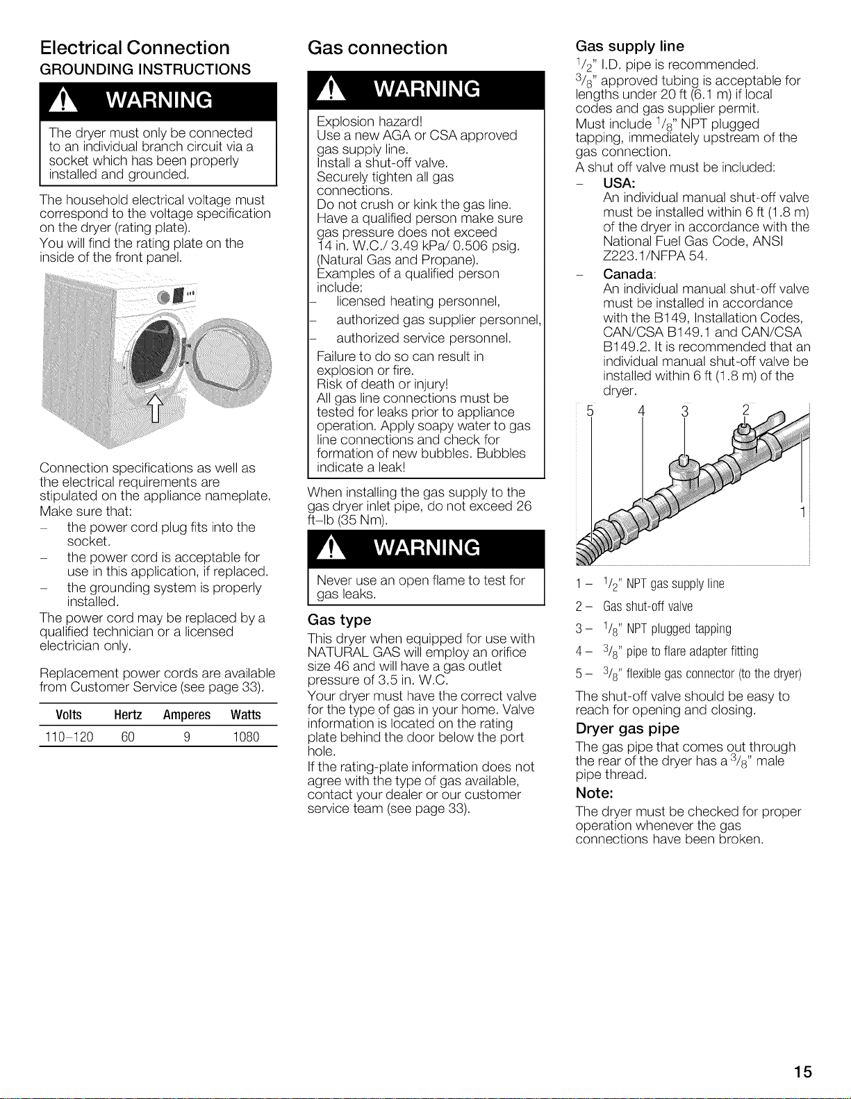
Gas supply line
1/2" I.D. pipe is recommended.
3/8" approved tubing is acceptable for
lengths under 20 ft (6.1 m) if local
codes and gas supplier permit.
Must include 1/8" NPT plugged
tapping, immediately upstream of the
gas connection.
A shut off valve must be included:
- USA:
An individual manual shut-off valve
must be installed within 6 ft (1.8 m)
of the dryer in accordance with the
National Fuel Gas Code, ANSI
Z223.1/NFPA 54.
- Canada:
An individual manual shut-off valve
must be installed in accordance
with the B149, Installation Codes,
CAN/CSA B149.1 and CAN/CSA
B149.2. It is recommended that an
individual manual shut-off valve be
installed within 6 ft (1.8 m) of the
dryer.
5 4 3 2
1- 1/2"NPTgassupplyline
2- Gasshut-0ffvalve
3- 1/8"NPTpluggedtapping
4- 3/8"pipetoflareadapterfitting
5- 3/8"flexiblegasconnector(tothedryer)
The shut-off valve should be easy to
reach for opening and closing.
Dryer gas pipe
The gas pipe that comes out through
the rear of the dryer has a 3/8" male
pipe thread.
Note:
The dryer must be checked for proper
operation whenever the gas
connections have been broken.
15
Connection of the dryer
Connection must be made by
a qualified technician.
The dryer must be disconnected
from the gas supply piping system
during pressure testing.
When using for the first time make
sure that there is no air in the piping
system.
Do not use copper pipes and tubing
if connected to natural gas.
Use a flexible gas connection
when installing a stacked dryer.
A hard, or rigid connection from the
house gas supply to the "stacked"
gas dryer is NOT allowed.
The connection may be different,
according to the supply line type, size
and location.
If local codes permit, use a flexible
stainless steel connector (Design
certified by the American Gas
Association or CSA International)
to connect the dryer.
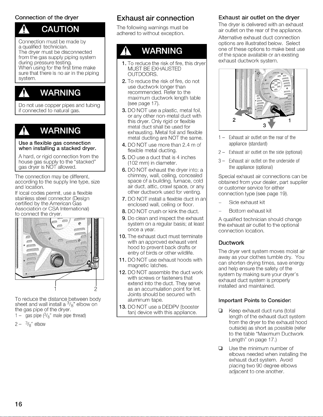
To reduce the distance between body
sheet and wall install a 3/8" elbow on
the gas pipe of the dryer.
1- gaspipe(3/8"malepipethread)
2- 3/8"elbow
Exhaust air connection
The following warnings must be
adhered to without exception.
.
To reduce the risk of fire, this dryer
MUST BE EXHAUSTED
OUTDOORS.
2. To reduce the risk of fire, do not
use ductwork longer than
recommended. Refer to the
maximum ductwork length table
(see page 17).
3. DO NOT use a plastic, metal foil,
or any other non-metal duct with
this dryer. Only rigid or flexible
metal duct shall be used for
exhausting. Metal foil and flexible
metal ducting are NOT the same.
4. DO NOT use more than 2.4 m of
flexible metal ducting.
5. DO use a duct that is 4 inches
(102 mm)in diameter.
6. DO NOT exhaust the dryer into: a
chimney, wall, ceiling, concealed
space of a building, furnace, cold
air duct, attic, crawl space, or any
other ductwork used for venting.
7. DO NOT install a flexible duct in an
enclosed wall, ceiling or floor.
8. DO NOT crush or kink the duct.
9.
Do clean and inspect the exhaust
system on a regular basis; at least
once a year.
10. The exhaust duct must terminate
with an approved exhaust vent
hood to prevent back drafts or
entry of birds or other wildlife.
11. DO NOT use exhaust hoods with
magnetic latches.
12. DO NOT assemble the duct work
with screws or fasteners that
extend into the duct. They serve
as an accumulation point for lint.
Joints should be secured with
aluminum tape.
13. DO NOT use a DEDPV (booster
fan) device with this appliance.
Exhaust air outlet on the dryer
The dryer is delivered with an exhaust
air outlet on the rear of the appliance.
Alternative exhaust duct connection
options are illustrated below. Select
one of these options to make best use
of the space available or an existing
exhaust ductwork system.
2
3
1- Exhaustairoutletontherearofthe
appliance(standard)
2- Exhaustairoutletontheside(optional)
3- Exhaustairoutletontheundersideof
the appliance(optional)
Special exhaust air connections can be
obtained from your dealer, part supplier
or customer service for either
connection type (see page 19).
- Side exhaust kit
- Bottom exhaust kit
A qualified technician should change
the exhaust air outlet to the optional
connection location.
Ductwork
The dryer vent system moves moist air
away as your clothes tumble dry. You
can shorten drying times, save energy
and help ensure the safety of the
system by making sure your dryer's
exhaust duct system is properly
installed and maintained.
Important Points to Consider:
E3
Keep exhaust duct runs (total
length of the exhaust duct system
from the dryer to the exhaust hood
outside) as short as possible (refer
to the table "Maximum Ductwork
Length" on page 17.)
E3
Use the minimum number of
elbows needed when installing the
exhaust duct system. Avoid
placing two 90 degree elbows
adjacent to one another.
16
E3 Check and clean the exhaust duct
system and exhaust hood at least
once each year, and any time you
suspect dryer performance is
decreased.
Remove accumulated lint to
prevent diminished airflow or
clogging of the system.
Professional cleaning is
recommended annually and when
attaching your dryer to a previously
used exhaust duct system.
Replace any plastic or metal foil
venting sections with rigid metal or
flexible metal ducting. Rigid metal
ducting is recommended.
[_ Correct exhaust system installation
is the responsibility of the
consumer.
[_ Problems that result from
incorrect installation are not
covered by the appliance
warranty.
Exhaust ducting which is longer than
specified in the maximum ductwork
length table on page 17 is not
permitted. Not adhering to this table
will extend drying time, cause lint to
accumulate and affect dryer
performance and life-time.
All joints should be tight to avoid leaks.
The male end of each duct section
must point away from the dryer.
Whether connecting to an existing
venting system or a new venting
system, make sure that all ducting is
clean and free of lint.
The maximum permitted length for
rigid duct and for rigid duct used with
flexible metal duct is shown inthe table
below. If using flexible metal ducting to
connect the appliance to the ductwork
system, the total length of flexible
metal duct used shall not exceed 2.4 m
and can only be used to connect the
dryer to the ductwork system. As the
table below shows, the maximum
overall ductwork length is reduced if
flexible ducting is used.
Maximum Ductwork Length
Numberof
90°Turns
or Elbows
0 66 ft. 45 ft.
1 56 ft. 36ft.
2 48 ft. 29ft.
3 39 ft. 22ft.
4 30ft. 16ft.
Note:
Side and bottom exhaust installations
have a 90°turn inside the dryer. Take
this into account when using the table
above.
The use of more than two 90° turns is
not recommended. For best
performance, separate all turns by at
least 4 ft. of straight duct, including
distance between last turn and exhaust
hood.
RigidDuct
(201 1 cm) (1372 cm)
(1707cm) (1097cm)
(1463cm) (884cm)
(1189cm) (671cm)
(914cm) (488cm)
FlexibleDuct
in
Combination
with Rigid
Duct
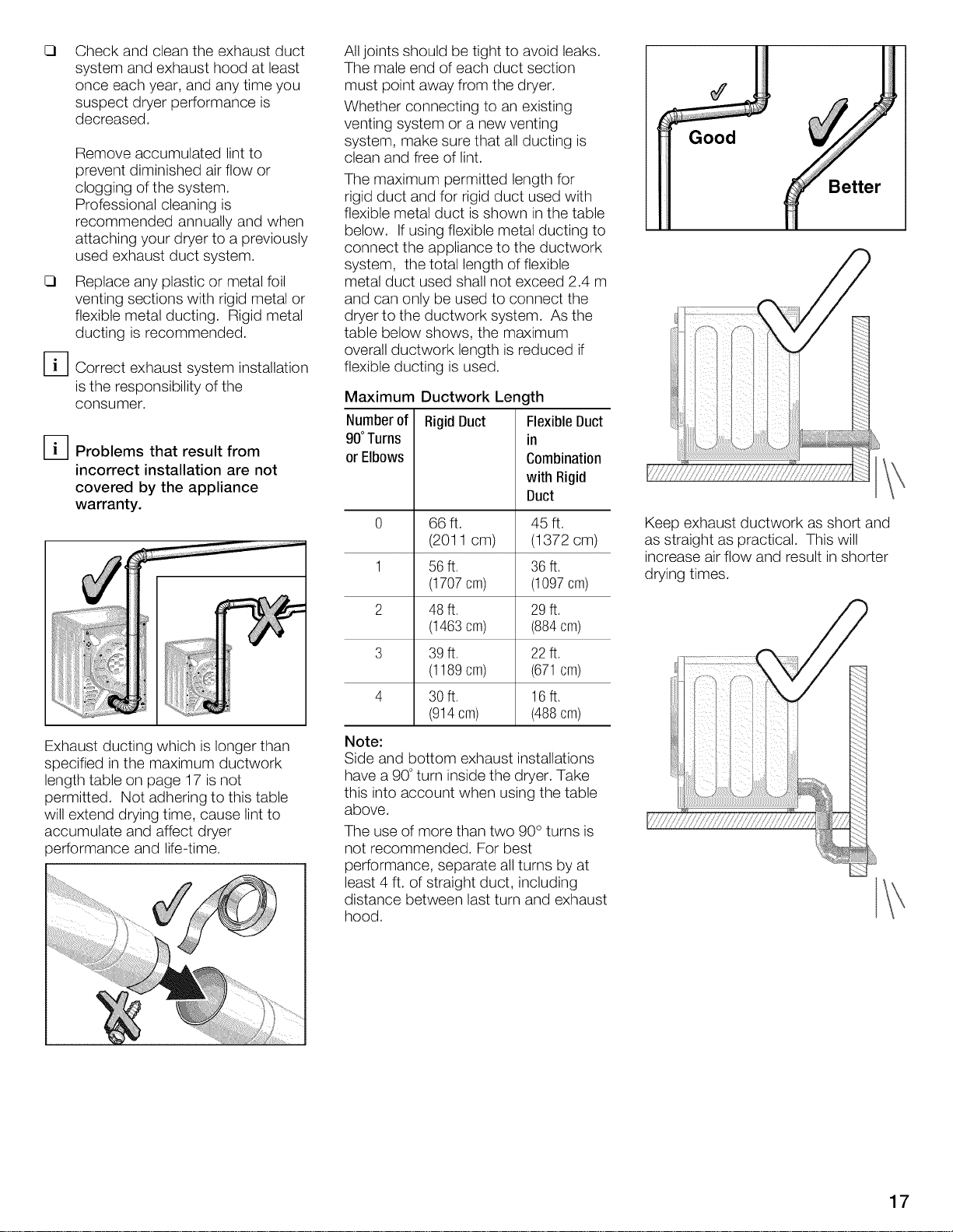
Good
Better
Keep exhaust ductwork as short and
as straight as practical. This will
increase air flow and result in shorter
drying times.
17
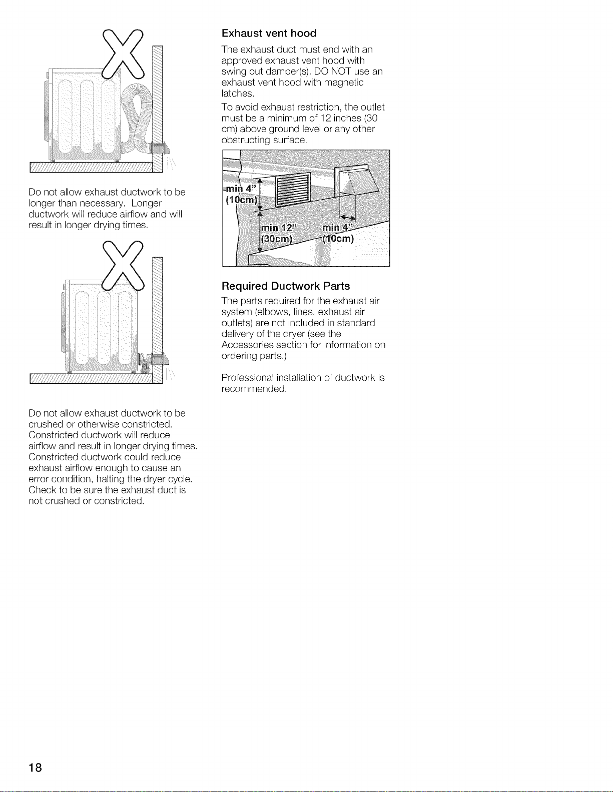
Do not allow exhaust ductwork to be
longer than necessary. Longer
ductwork will reduce airflow and will
result in longer drying times.
Exhaustventhood
The exhaust duct must end with an
approved exhaust vent hood with
swing out damper(s). DO NOT use an
exhaust vent hood with magnetic
latches.
To avoid exhaust restriction, the outlet
must be a minimum of 12 inches (30
cm) above ground level or any other
obstructing surface.
Required Ductwork Parts
The parts required for the exhaust air
system (elbows, lines, exhaust air
outlets) are not included in standard
delivery of the dryer (see the
Accessories section for information on
ordering parts.)
Do not allow exhaust ductwork to be
crushed or otherwise constricted.
Constricted ductwork will reduce
airflow and result in longer drying times.
Constricted ductwork could reduce
exhaust airflow enough to cause an
error condition, halting the dryer cycle.
Check to be sure the exhaust duct is
not crushed or constricted.
Professional installation of ductwork is
recommended.
18
Accessories
The following optional accessories for
your dryer may be obtained from
customer service (see page 33) or from
your local dealer. Please follow the
installation instructions supplied by the
appropriate manufacturer.
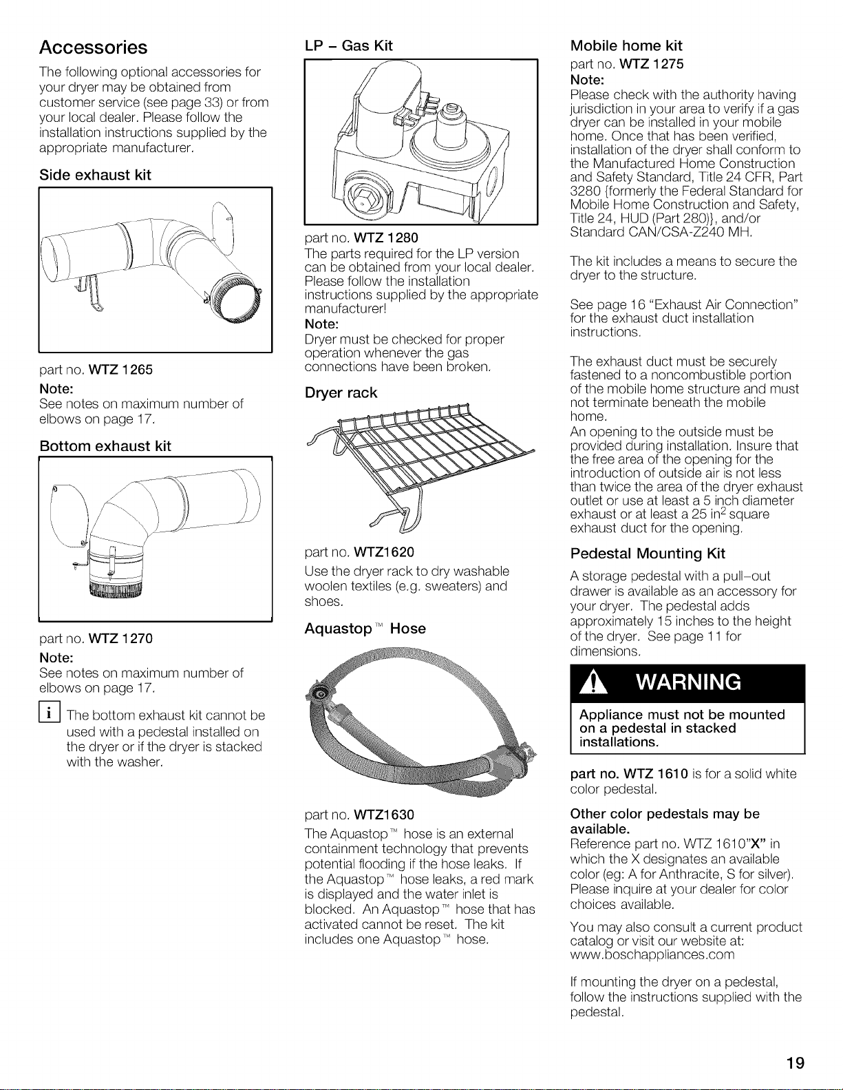
Side exhaust kit
i
o
part no. WTZ 1265
Note:
See notes on maximum number of
elbows on page 17.
Bottom exhaust kit
LP - Gas Kit
part no. WTZ 1280
The parts required for the LP version
can be obtained from your local dealer.
Please follow the installation
instructions supplied by the appropriate
manufacturer!
Note:
Dryer must be checked for proper
operation whenever the gas
connections have been broken.
Dryer rack
Mobile home kit
part no. WTZ 1275
Note:
Please check with the authority having
jurisdiction in your area to verify if agas
dryer can be installed in your mobile
home. Once that has been verified,
installation of the dryer shall conform to
the Manufactured Home Construction
and Safety Standard, Title 24 CFR, Part
3280 {formerly the Federal Standard for
Mobile Home Construction and Safety,
Title 24, HUD (Part 280)}, and/or
Standard CAN/CSA-Z240 MH.
The kit includes a means to secure the
dryer to the structure.
See page 16 "Exhaust Air Connection"
for the exhaust duct installation
instructions.
The exhaust duct must be securely
fastened to a noncombustible portion
of the mobile home structure and must
not terminate beneath the mobile
home.
An opening to the outside must be
provided during installation. Insure that
the free area of the opening for the
introduction of outside air is not less
than twice the area of the dryer exhaust
outlet or use at least a 5 inch diameter
exhaust or at least a 25 in2square
exhaust duct for the opening.
part no. WTZ 1270
Note:
See notes on maximum number of
elbows on page 17.
[_The bottom exhaust kit cannot be
used with a pedestal installed on
the dryer or if the dryer is stacked
with the washer.
part no. WTZ1620
Use the dryer rack to dry washable
woolen textiles (e.g. sweaters) and
shoes.
Aquastop TMHose
part no. WTZ1630
The Aquastop TMhose is an external
containment technology that prevents
potential flooding if the hose leaks. If
the Aquastop TMhose leaks, a red mark
is displayed and the water inlet is
blocked. An AquastopT_ hose that has
activated cannot be reset. The kit
includes one AquastopT_ hose.
Pedestal Mounting Kit
A storage pedestal with a pull-out
drawer is available as an accessory for
your dryer. The pedestal adds
approximately 15 inches to the height
of the dryer. See page 11 for
dimensions.
Appliance must not be mounted
on a pedestal in stacked
installations.
part no. WTZ 1610 isfor a solid white
color pedestal.
Other color pedestals may be
available.
Reference part no. WTZ 1610"X" in
which the X designates an available
color (eg: A for Anthracite, Sfor silver).
Please inquire at your dealer for color
choices available.
You may also consult a current product
catalog or visit our website at:
www.boschappliances.com
If mounting the dryer on a pedestal,
follow the instructions supplied with the
pedestal.
19
Stacking Kits
Use a flexible gas connection
when installing a stacked dryer.
A hard or rigid connection from the
house gas supply to the "stacked"
gas dryer is NOT allowed.
Risk of personal injury or death. DO
NOT stack the dryer on top of the
washer without the use of one of the
stacking kit accessories listed in this
manua.
There are two stacking kits available.
Basic Stacking Kit
This kit anchors the dryer on top of the
washer and adds approximately 0.63
inches (16 mm) to the stacked height.
See page 12 for dimensions.
part no. WTZ 1601 is for the basic
mechanical stacking kit.
Pull-Out Shelf Stacking Kit
This kit serves to stack the dryer on top
of the washer and also provides a pull-
out shelf. This kit adds approximately
1.52 inches (38.6 mm) to the stacked
washer/dryer height. See page 12 for
dimensions.
Preparing to transport the
dryer - step by step
D These procedures should only be
performed by a qualified person.
1. Close the shut-off valve.
2. Rotate the program selector
to "OFF".
.
Disconnect the power supply (turn
the circuit breaker off, unplug the
appliance).
.
Disconnect gas supply.
5.
Turn off the water faucet
connected to the water supply
hose (Steam models only).
Disconnect the water supply hose.
.
Disconnect the exhaust duct from
the exhaust air outlet on the dryer.
7.
Collect any accessories and
package them for shipment with
the appliance.
.
Close the door and secure with
adhesive tape.
9.
Screw the height-adjustable feet of
the dryer into the housing to
prevent them from being damaged
during transportation.
10.
Reinstallation of the Dryer at the
New Location - refer to the
Installation Instructions inthis
manual (see page 7).
This kit may also be combined with the
pedestal mounting kit to provide a
pull-out shelf as well as a combined
increase in height of the dryer of
approximately 16.5 inches.
[_The pedestal can not be combined
with the pull-out shelf stacking kit
in stacked washer/dryer
installations.
part no. WTZ 1600 is for the solid
white pull-out shelf stacking kit.
Other color pull-out shelf stacking
kits may be available.
Reference part no. WTZ 1600"X" in
which the X designates an available
color (eg: A for Anthracite, S for silver).
Please inquire at your dealer for color
choices available.
2O
OPERATING INSTRUCTIONS
Before using
To reduce the risk of fire, electric
shock, or injury to persons, read the
IMPORTANT SAFETY
INSTRUCTIONS before operating
this appliance.
Panel
O
Perm P_'e_g Cotto_
Time Br_f
Before using your dryer, read and
follow all installation and operating
instructions.
LED's
tl
11
L_t _t
Option
Buttons
Ddi¢ates
Start/Pause
Button
n
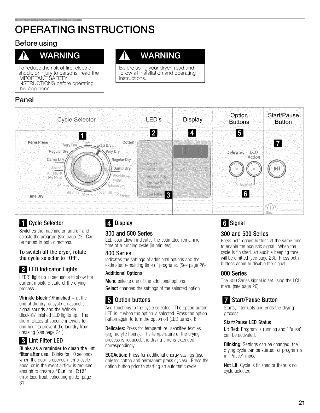
0 Cycle Selector
Switchesthemachineonandoff and
selectstheprogram(seepage23).Can
beturnedin bothdirections.
To switch off the dryer, rotate
the cycle selector to "Off".
LEDIndicator
LED'Slightup insequenceto showthe
currentmoisturestateofthe drying
process.
Wrinkle Block®/Finished - atthe
endofthedryingcycleanacoustic
signalsoundsandtheWrinkle
BIock®/FinishedLEDlightsup, The
drumrotatesatspecificintervalsfor
onehourto preventthe laundryfrom
creasing(seepage24),
Lights
_1 Lint Filter LED
Blinks as a reminderto cleanthe lint
filter after use. Blinksfor10seconds
whenthedoorisopenedaftera cycle
ends,or inthe eventairflowis reduced
enoughtocreatea "CLn"or"E:12"
error(seetroubleshootingguide,page
31),
Display
300 and 500 Series
LEDcountdownindicatesthe estimatedremaining
timeof a runningcycle(in minutes),
800 Series
Indicatesthe settingsofadditionaloptionsandthe
estimatedremainingtimeof programs.(Seepage26)
AdditionalOptions
Menuselectsoneof theadditionaloptions
Select changesthe settingsofthe selectedoption
Option buttons
Addfunctionsto the cycleselected.Theoptionbutton
LEDis litwhentheoptionis selected.Presstheoption
buttonagaintoturnthe optionoff(LEDturnsoff).
Delicates:Pressfortemperaturesensitivetextiles
(e.g.acrylicfibers). Thetemperatureof the drying
processisreduced,thedryingtimeis extended
correspondingly.
ECOAction:Pressforadditionalenergysavings(use
onlyfor cottonandpermanentpresscycles),Pressthe
optionbuttonpriorto startinganautomaticcycle,
r_ Signal
300 and 500 Series
Pressbothoptionbuttonsatthesametime
to enabletheacousticsignal, Whenthe
cycleis finished,anaudiblebeepingtone
willbe emitted(seepage23). Pressboth
buttonsagainto disablethesignal.
800 Series
The800 SeriessignalissetusingtheLCD
menu(seepage26),
Start/Pause Button
Starts,interruptsandendsthedrying
process,
Start/PauseLEOStatus
Lit Red:Programis runningand"Pause"
canbeactivated,
Blinking: Settingscanbechanged,the
dryingcyclecanbestarted,or programis
in "Pause"mode.
Not Lit: Cycleisfinishedor thereis no
cycleselected.
21
Additional Safety
Information
To reduce the risk of fire, electric
shock, or injury to persons, always
follow the IMPORTANT SAFETY
INSTRUCTIONS
(see page 5).
Protection of the
environment
Tips on saving energy
To save energy, money and time,
Bosch recommends the following:
Drain the laundry thoroughly!
Before drying, spin the laundry
thoroughly in the washing
machine. Use the highest possible
spin speed for the type of laundry!
Higher washer spin speeds reduce
residual moisture and decrease
drying time and energy
consumption.
Use optimum load!
Use larger loads, up to the
maximum recommended loads for
the cycle and laundry type.
However, do not exceed
maximum recommended load
capacity.
Clean the lint filter!
Check the lint filter before using
the dryer each time and clean the
filter as needed. Making sure the
lint filter is clean before beginning
each drying load results in
improved airflow and reduced
drying time. (see page 28)
Ventilate the room!
Provide an adequate supply
of fresh air during the drying
process.
Do not dry unsuitable materials!
Do not dry rubberized or air-tight
items.
Temporary
disconnection of
the dryer
Operate your dryer only when you are
at home. Ifyou plan to go on vacation
or are not using your dryer for an
extended period of time, you should:
1. Turn off the circuit breaker.
2. Unplug the power supply plug if
possible.
3. Clean the lint filter.
4. Turn off the water supply (applies
only to Steam dryers).
5. Turn off the gas supply.
Laundry
Identification of fabrics
Observe the treatment symbols on the
textile labels. They provide valuable
information as well as limitations about
the drying process.
Do not dry the following textiles in the
dryer:
Air-tight textiles (e.g. rubberized)
Delicate fabrics (silk, synthetic
curtains)
%
Dry woolen or wool-rich textiles
with the dryer rack only!
%
Use the time program "Air fluff/No
heat" to dry articles containing
foam rubber or similarly textured
rubber-like materials.
Drying tips
In principle, the following applies to all
drying programs:
- To ensure a uniform drying result,
sort the laundry according to fabric
type and drying cycle selected.
Fasten zippers, hooks and eyes,
loose belts, apron strings, etc.
Do not overdry easy-care laundry
to reduce the risk of wrinkling!
Hang laundry up promptly to dry in
the air.
Do not iron laundry immediately
after drying. Place the laundry in a
pile for a short while. Residual
moisture will then be distributed
uniformly.
Knit textiles (e.g. T-shirts,
sweatshirts, and other similar
types of laundry) often shrink when
dried for the first time. Do not use
the "Very dry/Extra dry" cycles the
first time you dry these types of
laundry to reduce potential
shrinkage.
Some items such as these can
also shrink during later laundering.
Use caution in cycle selection to
avoid shrinkage.
Clean and inspect the exhaust
system on a regular basis!
Blockages may extend drying time
or may cause the dryer to
malfunction.
22
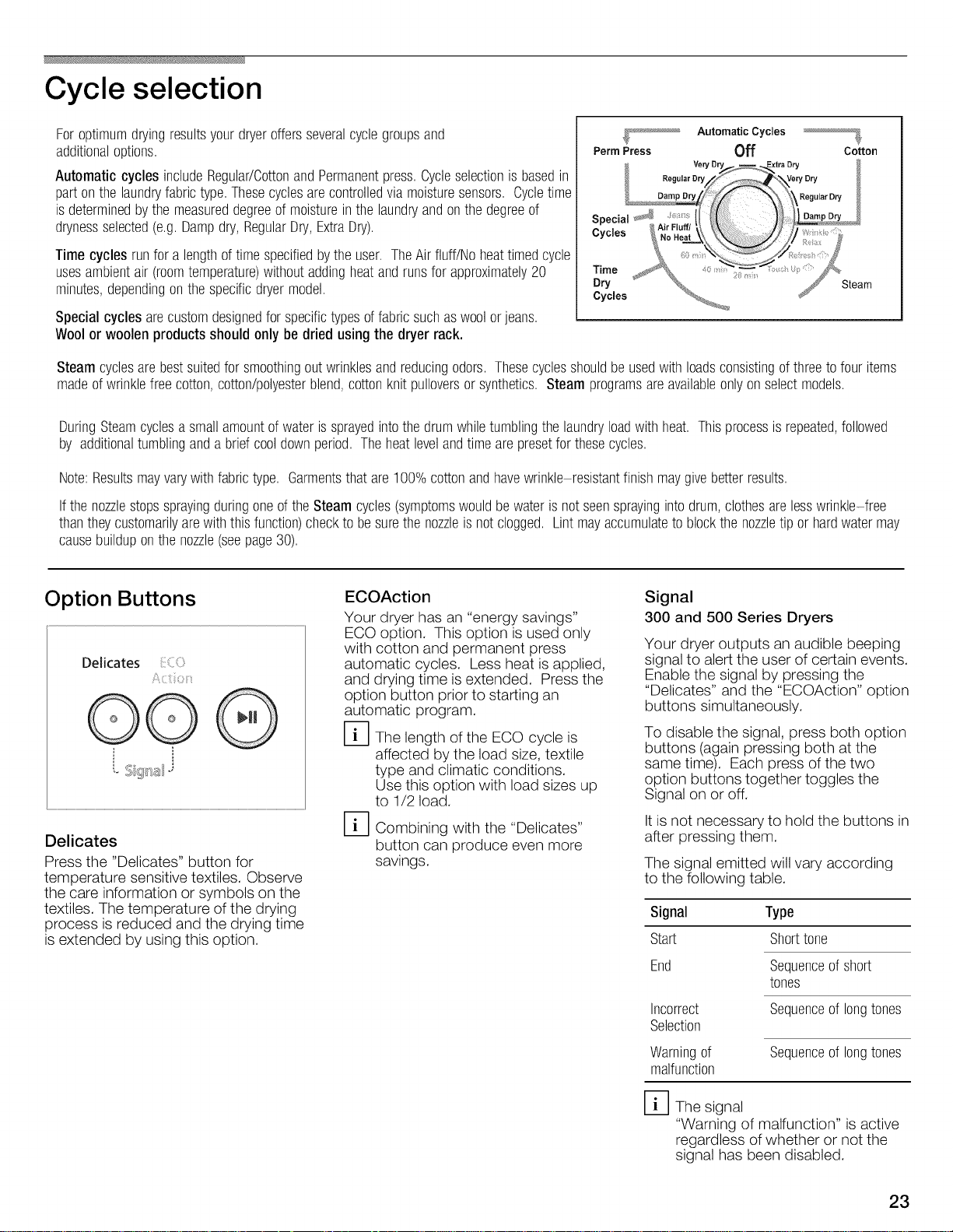
Cycle selection
Foroptimumdryingresultsyourdryeroffersseveralcyclegroupsand
additionaloptions.
Automatic cycles includeRegular/CottonandPermanentpress.Cycleselectionis basedin
partonthe laundryfabrictype.Thesecyclesarecontrolledvia moisturesensors. Cycletime
isdeterminedbythe measureddegreeof moistureinthe laundryandonthedegreeof
drynessselected(e.g.Dampdry,RegularDry,ExtraDry).
Time cycles runfora lengthoftimespecifiedbytheuser. TheAir fluff/Noheattimedcycle
usesambientair (roomtemperature)withoutaddingheatandrunsfor approximately20
minutes,dependingon thespecificdryermodel.
Specialcycles arecustomdesignedfor specifictypesoffabricsuchaswoolor jeans.
Woolor woolen productsshould only bedried using the dryer rack.
Steam cyclesarebestsuitedforsmoothingoutwrinklesandreducingodors. Thesecyclesshouldbe usedwithloadsconsistingofthreetofour items
madeofwrinklefreecotton,cotton/polyesterblend,cottonknitpulloversorsynthetics.Steamprogramsareavailableonlyonselectmodels.
DuringSteamcyclesasmallamountofwateris sprayedintothedrumwhiletumblingthelaundryloadwithheat. Thisprocessisrepeated,followed
by additionaltumblingandabrief cooldownperiod.Theheatlevelandtimearepresetfor thesecycles.
Note:Resultsmayvarywithfabrictype. Garmentsthatare100%cottonandhavewrinkle resistantfinishmaygivebetterresults.
Ifthe nozzlestopssprayingduringoneoftheSteamcycles(symptomswouldbe wateris notseensprayingintodrum,clothesarelesswrinkle-free
thantheycustomarilyarewiththisfunction)checkto besurethe nozzleis notclogged.Lintmayaccumulateto blockthenozzletip or hardwatermay
causebuilduponthe nozzle(seepage30).
Perm Press Off Cotton
Automatic Cycles
Option Buttons
Delicates C:
C
O0
L i_'_
Delicates
Press the "Delicates" button for
temperature sensitive textiles. Observe
the care information or symbols on the
textiles. The temperature of the drying
process is reduced and the drying time
is extended by using this option.
ECOAction
Your dryer has an "energy savings"
ECO option. This option is used only
with cotton and permanent press
automatic cycles. Less heat is applied,
and drying time is extended. Press the
option button prior to starting an
automatic program.
D The length of the ECO cycle is
affected by the load size, textile
type and climatic conditions.
Use this option with load sizes up
to 1/2 load.
D Combining with the "Delicates"
button can produce even more
savings.
Signal
300 and 500 Series Dryers
Your dryer outputs an audible beeping
signal to alert the user of certain events.
Enable the signal by pressing the
"Delicates" and the "ECOAction" option
buttons simultaneously.
To disable the signal, press both option
buttons (again pressing both at the
same time). Each press of the two
option buttons together toggles the
Signal on or off.
It is not necessary to hold the buttons in
after pressing them.
The signal emitted will vary according
to the following table.
Signal Type
Start Shorttone
End
Incorrect
Selection
Sequenceofshort
tones
Sequenceof longtones
Warningof
malfunction
D The signal
"Warning of malfunction" is active
regardless of whether or not the
signal has been disabled.
Sequenceof longtones
23
LED Indicators of Cycle
Sequence
The dryer uses an electronic scanning
system for all cycles except the time
cycles. A moisture sensor continuously
checks the moisture in the laundry.
Drying ends automatically as soon as
the selected degree of dryness has
been reached.
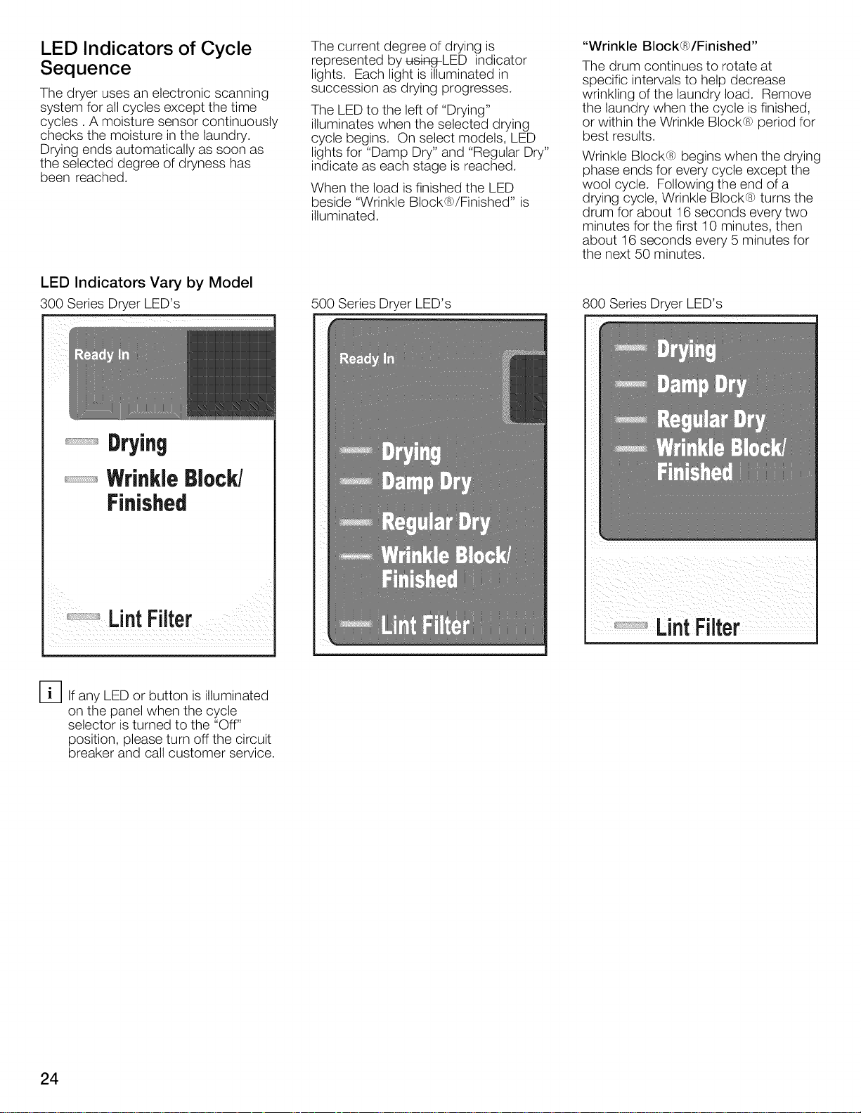
LED Indicators Vary by Model
300 Series Dryer LED's
Drying
The current degree of drying is
represented by u_J_-LED indicator
lights. Each light is illuminated in
succession as drying progresses.
The LED to the left of "Drying"
illuminates when the selected drying
cycle begins. On select models, LED
lights for "Damp Dry" and "Regular Dry"
indicate as each stage is reached.
When the load is finished the LED
beside "Wrinkle Block /Finished is
illuminated.
500 Series Dryer LED's
"Wrinkle Block®/Finished"
The drum continues to rotate at
specific intervals to help decrease
wrinkling of the laundry load. Remove
the laundry when the cycle is finished,
or within the Wrinkle Block® period for
best results.
Wrinkle Block® begins when the drying
phase ends for every cycle except the
wool cycle. Following the end of a
drying cycle, Wrinkle Block® turns the
drum for about 16 seconds every two
minutes for the first 10 minutes, then
about 16 seconds every 5 minutes for
the next 50 minutes.
800 Series Dryer LED's
WrinkleBlock/
Finished
il _i i iii
Lnt ter
[_lf any LED or button is illuminated
on the panel when the cycle
selector is turned to the "Off"
position, please turn off the circuit
breaker and call customer service.
24
Cycle Selection Table
Cotton
ForCottonsandcoloredsmadeofcottonorlinen,Pressthe"Delicates"optionbuttonfortemperature-sensitivetextiles,
Bedlinen,tablelinen,towels
Dampdry Bedlinenandtablelinen,towels,T-shirts,sportsshirts,overalls
T-shirts,sportsshirts,dresses,trousers,overalls,underwear
Terrytowels,kitchentowels,handtowels,bedlinen, underwear,cotton notto beironed
Regulardry socks
Terrytowels,kitchentowels,handtowels,bedlinen, underwear,cotton notto beironed,thickmulti-ply
Verydry socks
Extradry Terrybathrobesandterrybedlinen particularlythickor multi-ply
Permanent Press
Easy-care(drip-dry)laundrymadeofsyntheticandblendedfabric(e.g.cotton/polyester).Pressthe "Delicates"buttonfor verytemperature-sensitive
textiles.
Trousers,dresses,skirts,shirts,blouses,leggings,sportsclothingwith to be ironedoronlylightlyironed
Dampdry synthetic-richfibers, lingerie
Regulardry Shirts,blouses,sportsclothing notto beironed
Verydry Bedlinenandtablelinen,tracksuits,comforters,blankets notto beironed,thickmulti-ply
to beironed
Cotton,cotton polyesterblends,commonknitsandsyntheticshirts,cottonblendpants,skirts,t shirtsandpullovers.
Steam Refresh
Wrinklefreefabricsgivebestresults.
Helpssmoothoutwrinklesandreduceodors.Usewitha lightload,suchasoneconsistingof 3 to4 shirts. Program
time isabout16minutes.
Steam Wrinkle relax Helpssmoothoutwrinkles.Usewitha light load,suchasoneconsistingof 3to 4 shirts. Programtime is about12
minutes.
Thisprogramis usedto refresha cottontextileloadthat hasbeendriedandhasbeenleftin the drumofthedryerat
Steam Touch up theendofthe cycleovernight.This20minuteprogramrefreshestheloadto helpsmoothoutthewrinklescausedby
the loadpressingdownunderitsownweight.
Clothingcontainingfoam,rubber,or plasticmustberefreshedona clothes lineor byusingtheAir fluff/Noheat
cycleasthesearticlesmayignitedueto theheatoftheSteamprogram.
Wool
Washablewoolentextiles(e.g.sweaters,woolenpullover,skirts)
Dry woolen or wool-rich textiles with dryer rack only!
Jeans (5ooSeries) Heavyjeanfabric
DarkColor(800Series) Darkcoloredtextiles(e.g. heavy,darkclothes(cotton))
Active Wear (8ooSeries) Smallloads,loadsthat needa shortdryingtime(e.g.sportsshirts,work out clothes(polyester,nylon,synthetic))
20, 40 min.,60 min. (3oo/5oo
Series)
Pre-driedtextileswith lowmoisturecontent,individualsmallitems,e.g.bathtowels,bathingsuits,dishcloths.
Forthe smallestloadingconditionfrom 0.22 Ib- 0.44Ib (i.e.onesmalltowel),for this atime dryprogramshouldbe
selected.
Medium + requireddryingtime
(800Series)
(800 Series) if you choose a
program with variable time (e.g. time
programs, wool care) the display
starts to flash. You have to set the
time,
Air fluff / Noheat (300/500Series)
Air fluff / No heat+ required
time(800Series)
Pressthe"Delicates"buttonfortemperature-sensitivetextilesoption,
Cottonsandcoloredsmadeof cottonor linen,
Fresheningor airinglittle-wornitemsofclothinganddryingof extremelysensitivetextiles.
Forall textiletypesincludingfoamrubber(e.g.pillows,stuffedtoys),plastic(e.g.showercurtains,tableclothes),
rubber(e.g.backedrugs),sheernylon,olefin.
25
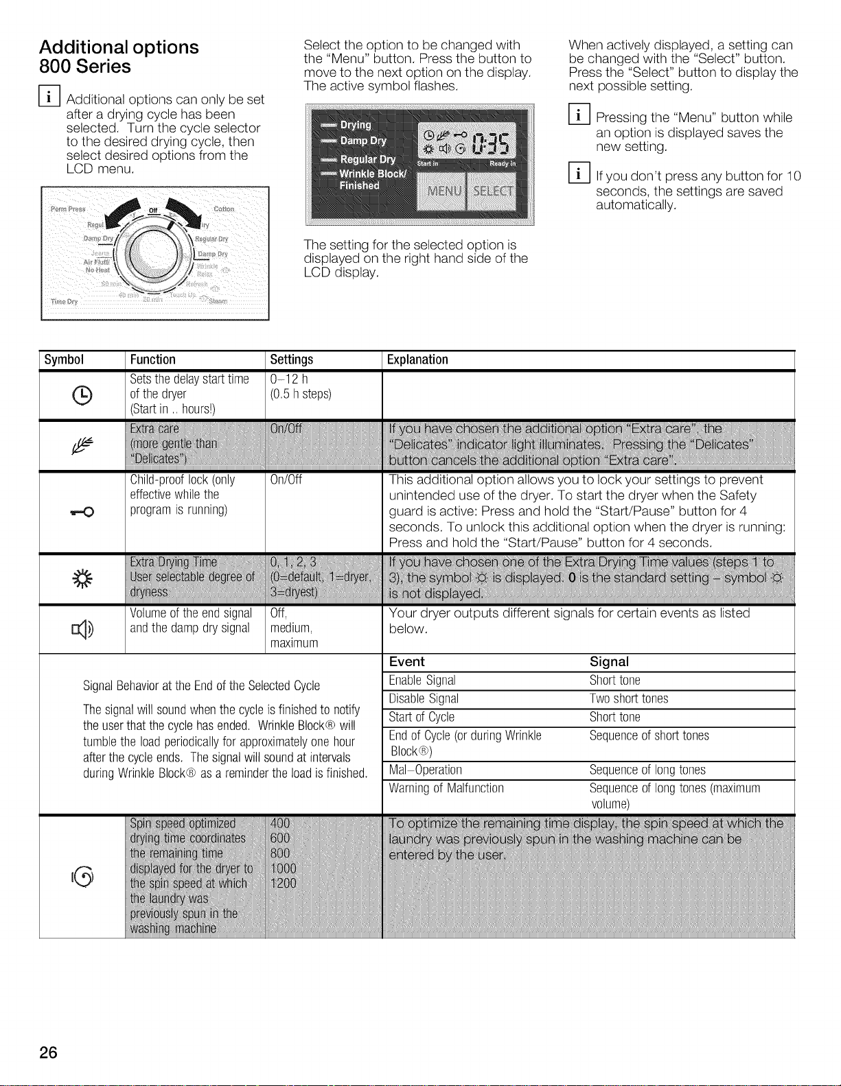
Additional options
800 Series
I-_1 Additional options can only be set
after a drying cycle has been
selected. Turn the cycle selector
to the desired drying cycle, then
select desired options from the
LCD menu.
Symbol Function Settings Explanation
Setsthedelaystarttime 0-12 h
(_ ofthe dryer (0.5hsteps)
(Startin .. hours!)
Select the option to be changed with
the "Menu" button. Press the button to
move to the next option on the display.
The active symbol flashes.
The setting for the selected option is
displayed on the right hand side of the
LCD display.
When actively displayed, a setting can
be changed with the "Select" button.
Press the "Select" button to display the
next possible setting.
D Pressing the "Menu" button while
an option is displayed saves the
new setting.
D If you don't press any button for 10
seconds, the settings are saved
automatically.
Child-prooflock(only
effectivewhilethe
!-O
q,)
SignalBehaviorattheEndofthe SelectedCycle
Thesignalwill soundwhenthe cycleisfinishedto notify
theuserthatthe cyclehasended.WrinkleBlock@will
tumblethe loadperiodicallyforapproximatelyonehour
afterthecycleends, Thesignalwill soundatintervals
duringWrinkleBlock@asa reminderthe loadisfinished.
programis running)
Volumeofthe endsignal
andthedampdry signal
0n/0ff
Off,
medium,
maximum
This additional option allows you to lock your settings to prevent
unintended use of the dryer. To start the dryer when the Safety
guard isactive: Press and hold the "Start/Pause" button for 4
seconds. To unlock this additional option when the dryer is running:
Press and hold the "Start/Pause" button for 4 seconds.
Your dryer outputs different signals for certain events as listed
below.
Event
EnableSignal
DisableSignal
Startof Cycle
Endof Cycle(orduringWrinkle Sequenceof shorttones
Block@)
Mal Operation Sequenceof longtones
Warningof Malfunction Sequenceof longtones(maximum
Signal
Sho_tone
Twoshorttones
Sho_tone
volume)
26
'G
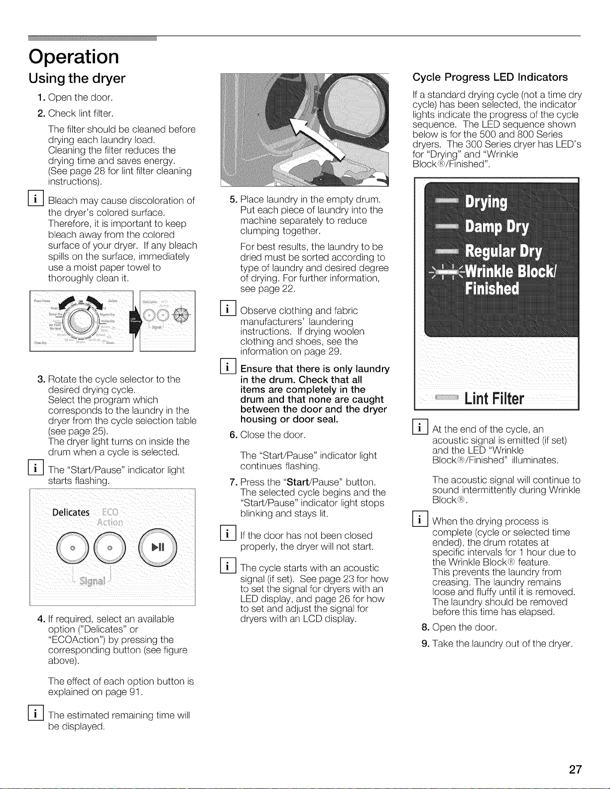
Operation
Using the dryer
1. Open the door.
2. Check lint filter.
The filter should be cleaned before
drying each laundry load.
Cleaning the filter reduces the
drying time and saves energy.
(See page 28 for lint filter cleaning
instructions).
[_ Bleach may cause discoloration of
the dryer's colored surface.
Therefore, it is important to keep
bleach away from the colored
surface of your dryer. If any bleach
spills on the surface, immediately
use a moist paper towel to
thoroughly clean it.
3. Rotate the cycle selector to the
desired drying cycle.
Select the program which
corresponds to the laundry in the
dryer from the cycle selection table
(see page 25).
The dryer light turns on inside the
drum when a cycle is selected.
[_The "Start/Pause" indicator light
starts flashing.
4. If required, select an available
option ("Delicates" or
"ECOAction") by pressing the
corresponding button (see figure
above).
5,
Place laundry in the empty drum.
Put each piece of laundry into the
machine separately to reduce
clumping together.
For best results, the laundry to be
dried must be sorted according to
type of laundry and desired degree
of drying. For further information,
see page 22.
%
Observe clothing and fabric
manufacturers' laundering
instructions. If drying woolen
clothing and shoes, see the
information on page 29.
%
Ensure that there is only laundry
in the drum. Check that all
items are completely in the
drum and that none are caught
between the door and the dryer
housing or door seal.
6. Close the door.
The "Start/Pause" indicator light
continues flashing.
7,
Press the "Start/Pause" button.
The selected cycle begins and the
"Start/Pause" indicator light stops
blinking and stays lit.
%
If the door has not been closed
properly, the dryer will not start.
%
The cycle starts with an acoustic
signal (if set). See page 23 for how
to set the signal for dryers with an
LED display, and page 26 for how
to set and adjust the signal for
dryers with an LCD display.
Cycle Progress LED Indicators
If a standard drying cycle (not a time dry
cycle) has been selected, the indicator
lights indicate the progress of the cycle
sequence. The LED sequence shown
below is for the 500 and 800 Series
dryers. The 300 Series dryer has LED's
for "Drying" and "Wrinkle
Block®/Finished".
LintFilter
%
At the end of the cycle, an
acoustic signal is emitted (ifset)
and the LED "Wrinkle
Block®/Finished" illuminates.
The acoustic signal wiii continue to
sound intermittently during Wrinkle
Block®.
%
When the drying process is
complete (cycle or selected time
ended), the drum rotates at
specific intervals for 1 hour due to
the Wrinkle Block® feature.
This prevents the laundry from
creasing. The laundry remains
loose and fluffy until it is removed.
The laundry should be removed
before this time has elapsed.
8. Open the door.
9. Take the laundry out of the dryer.
The effect of each option button is
explained on page 91.
[_The estimated remaining time will
be displayed.
27
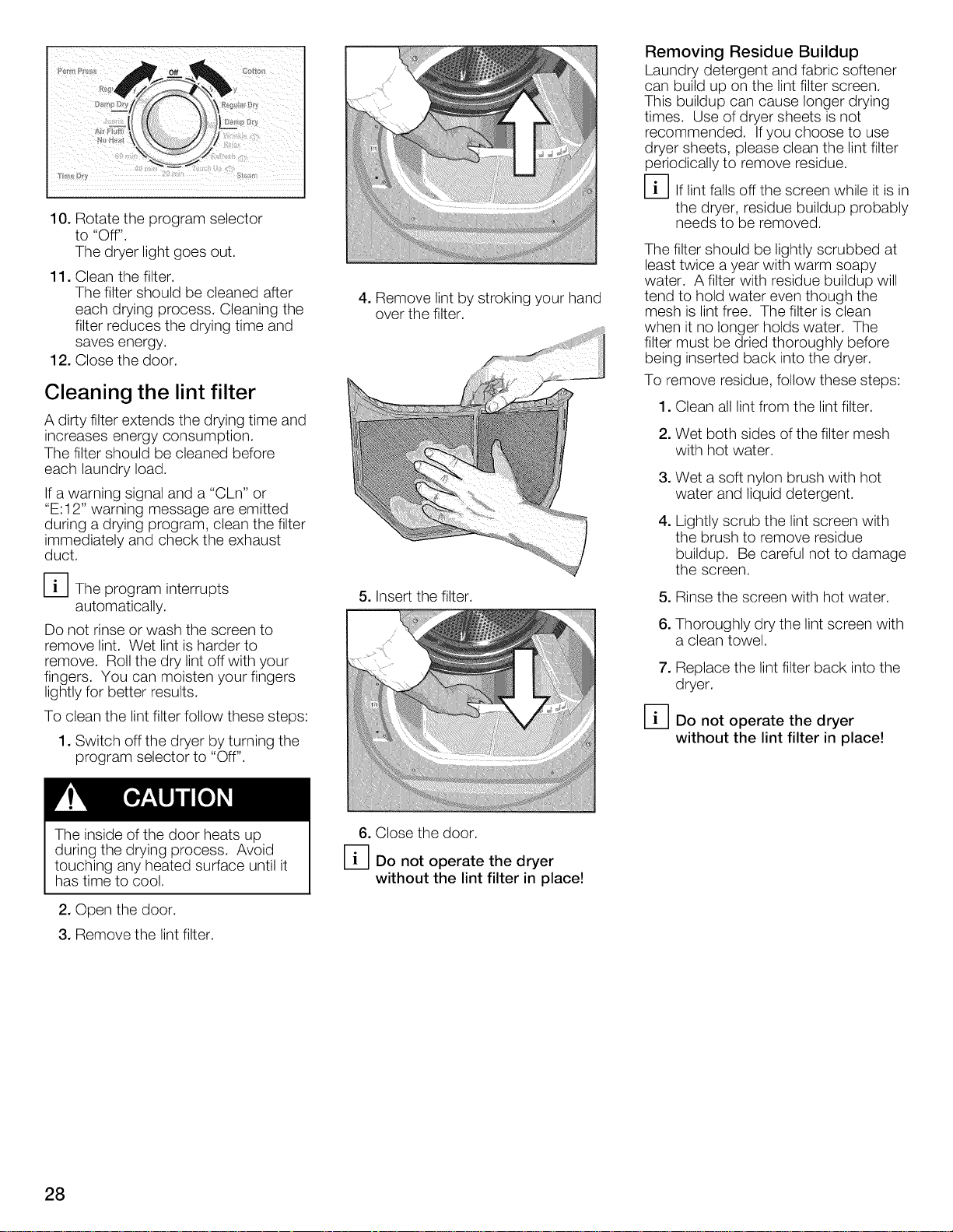
10. Rotate the program selector
to "Off".
The dryer light goes out.
11. Clean the filter.
The filter should be cleaned after
each drying process. Cleaning the
filter reduces the drying time and
saves energy.
12. Close the door.
Cleaning the lint filter
A dirty filter extends the drying time and
increases energy consumption.
The filter should be cleaned before
each laundry load.
If a warning signal and a "CLn" or
"E:I 2" warning message are emitted
during a drying program, clean the filter
immediately and check the exhaust
duct.
[_The program interrupts
automatically.
Do not rinse or wash the screen to
remove lint. Wet lint is harder to
remove. Roll the dry lint off with your
fingers. You can moisten your fingers
lightly for better results.
To clean the lint filter follow these steps:
1. Switch off the dryer by turning the
program selector to "Off".
4. Remove lint by stroking your hand
over the filter.
5. Insert the filter.
Removing Residue Buildup
Laundry detergent and fabric softener
can build up on the lint filter screen.
This buildup can cause longer drying
times. Use of dryer sheets is not
recommended. Ifyou choose to use
dryer sheets, please clean the lint filter
periodically to remove residue.
D If lint falls off the screen while it is in
the dryer, residue buildup probably
needs to be removed.
The filter should be lightly scrubbed at
least twice a year with warm soapy
water. A filter with residue buildup will
tend to hold water even though the
mesh is lint free. The filter is clean
when it no longer holds water. The
filter must be dried thoroughly before
being inserted back into the dryer.
To remove residue, follow these steps:
1. Clean all lint from the lint filter.
2. Wet both sides of the filter mesh
with hot water.
3. Wet a soft nylon brush with hot
water and liquid detergent.
4. Lightly scrub the lint screen with
the brush to remove residue
buildup. Be careful not to damage
the screen.
5. Rinse the screen with hot water.
6. Thoroughly dry the lint screen with
a clean towel.
7. Replace the lint filter back into the
dryer.
D Do not operate the dryer
without the lint filter in place!
The inside of the door heats up
during the drying process. Avoid
touching any heated surface until it
has time to cool.
2. Open the door.
3. Remove the lint filter.
28
6. Close the door.
D Do not operate the dryer
without the lint filter in place!
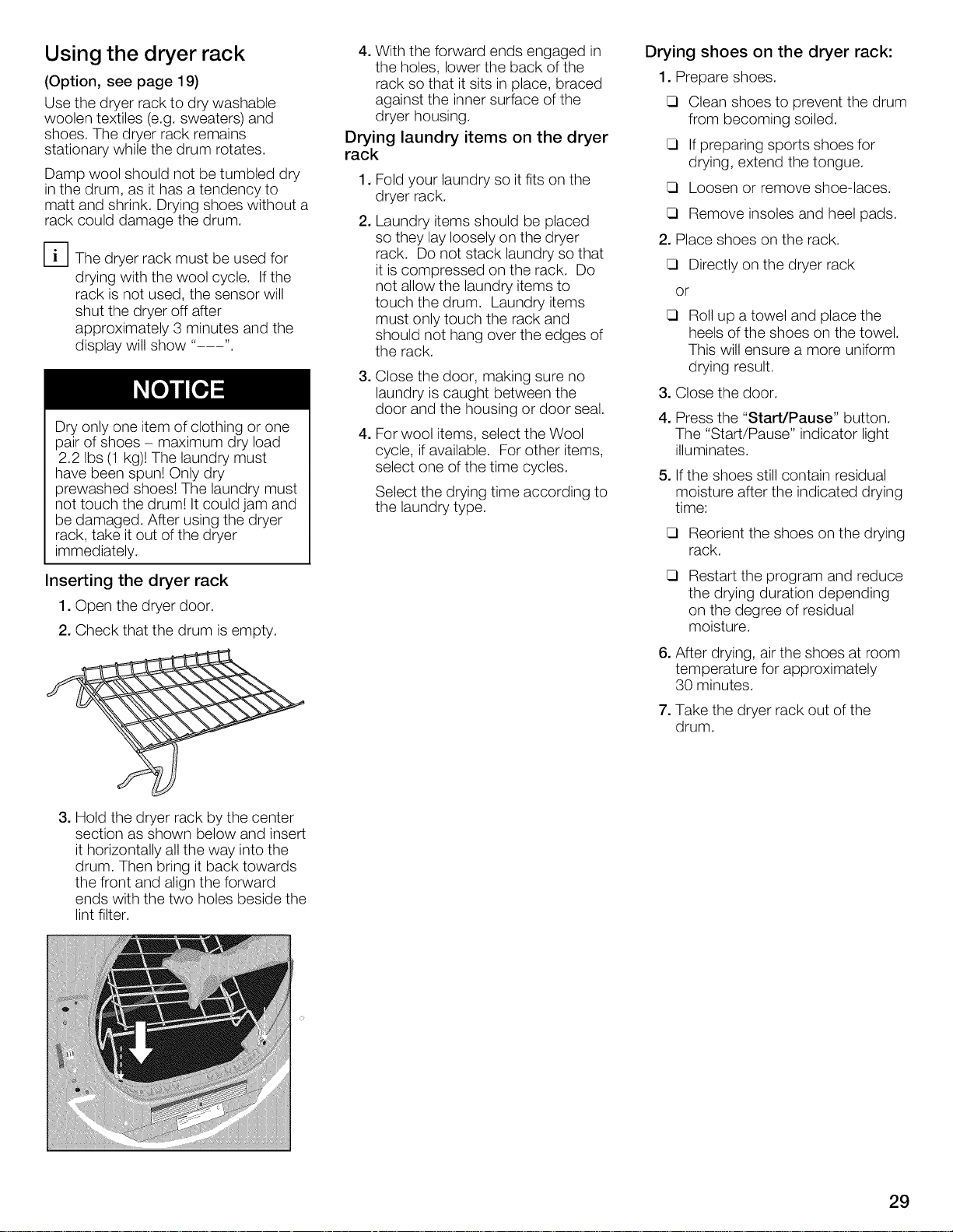
Using the dryer rack
(Option, see page 19)
Use the dryer rack to dry washable
woolen textiles (e.g. sweaters) and
shoes. The dryer rack remains
stationary while the drum rotates.
Damp wool should not be tumbled dry
in the drum, as it has a tendency to
matt and shrink. Drying shoes without a
rack could damage the drum.
[_The dryer rack must be used for
drying with the wool cycle. If the
rack is not used, the sensor will
shut the dryer off after
approximately 3 minutes and the
display will show ....
Dry only one item of clothing or one
pair of shoes - maximum dry load
2.2 Ibs (1 kg)! The laundry must
have been spun! Only dry
prewashed shoes! The laundry must
not touch the drum! It could jam and
be damaged. After using the dryer
rack, take it out of the dryer
immediately.
Inserting the dryer rack
1. Open the dryer door.
2. Check that the drum is empty.
4. With the forward ends engaged in
the holes, lower the back of the
rack so that it sits in place, braced
against the inner surface of the
dryer housing.
Drying laundry items on the dryer
rack
,
Fold your laundry so it fits on the
dryer rack.
2.
Laundry items should be placed
so they lay loosely on the dryer
rack. Do not stack laundry so that
it is compressed on the rack. Do
not allow the laundry items to
touch the drum. Laundry items
must only touch the rack and
should not hang over the edges of
the rack.
,
Close the door, making sure no
laundry is caught between the
door and the housing or door seal.
,
For wool items, select the Wool
cycle, ifavailable. For other items,
select one of the time cycles.
Select the drying time according to
the laundry type.
Drying shoes on the dryer rack:
1. Prepare shoes.
Clean shoes to prevent the drum
from becoming soiled.
If preparing sports shoes for
drying, extend the tongue.
Loosen or remove shoe-laces.
Remove insoles and heel pads.
2. Place shoes on the rack.
Directly on the dryer rack
or
Roll up a towel and place the
heels of the shoes on the towel.
This will ensure a more uniform
drying result.
3. Close the door.
4. Press the "Start/Pause" button.
The "Start/Pause" indicator light
illuminates.
5. If the shoes still contain residual
moisture after the indicated drying
time:
Reorient the shoes on the drying
rack.
E3
Restart the program and reduce
the drying duration depending
on the degree of residual
moisture.
6. After drying, air the shoes at room
temperature for approximately
30 minutes.
7. Take the dryer rack out of the
drum.
3. Hold the dryer rack by the center
section as shown below and insert
it horizontally all the way into the
drum. Then bring it back towards
the front and align the forward
ends with the two holes beside the
lint filter.
29
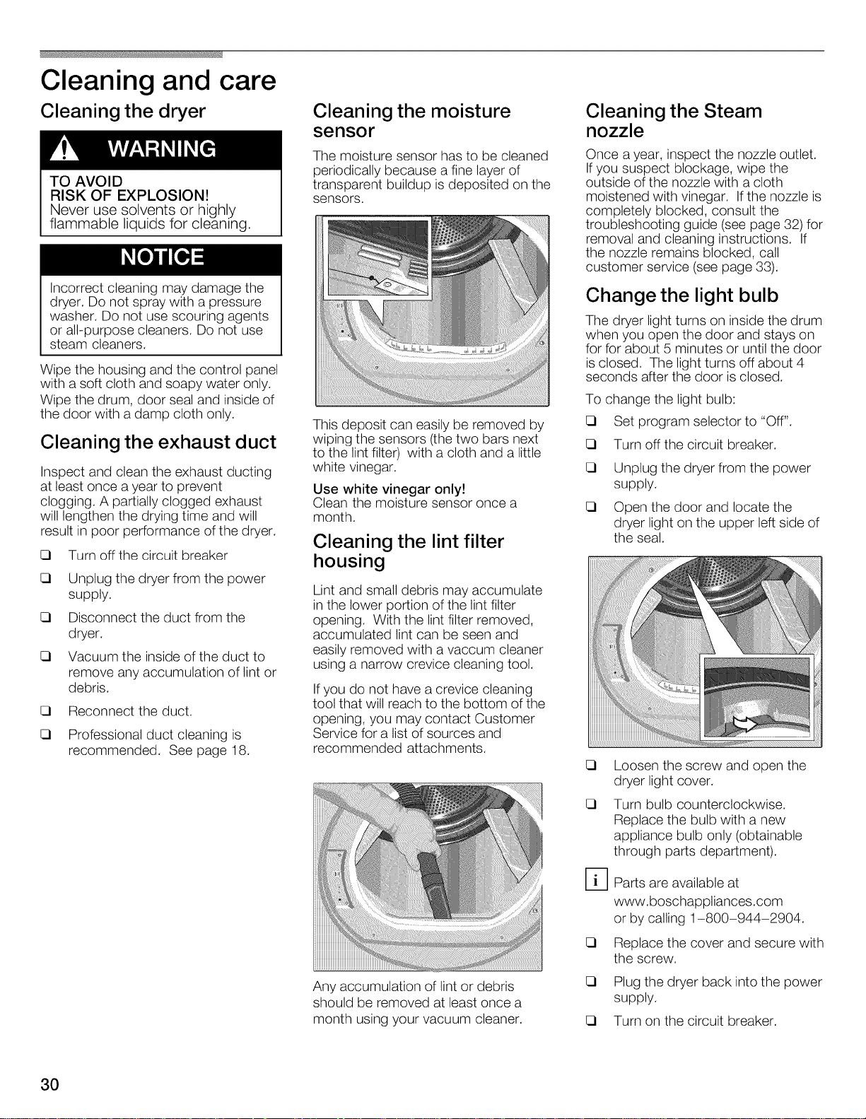
Cleaning and care
Cleaning the dryer
TO AVOID
RISK OF EXPLOSION!
Never use solvents or highly
flammable liquids for cleaning.
Incorrect cleaning may damage the
dryer. Do not spray with a pressure
washer. Do not use scouring agents
or all-purpose cleaners. Do not use
steam cleaners.
Wipe the housing and the control panel
with a soft cloth and soapy water only.
Wipe the drum, door seal and inside of
the door with a damp cloth only.
Cleaning the exhaust duct
Inspect and clean the exhaust ducting
at least once a year to prevent
clogging. A partially clogged exhaust
will lengthen the drying time and will
result in poor performance of the dryer.
13 Turn off the circuit breaker
13 Unplug the dryer from the power
supply.
13 Disconnect the duct from the
dryer.
13 Vacuum the inside of the duct to
remove any accumulation of lint or
debris.
13 Reconnect the duct.
13 Professional duct cleaning is
recommended. See page 18.
Cleaning the moisture
sensor
The moisture sensor has to be cleaned
periodically because afine layer of
transparent buildup is deposited on the
sensors.
This deposit can easily be removed by
wiping the sensors (the two bars next
to the lint filter) with a cloth and a little
white vinegar.
Use white vinegar only!
Clean the moisture sensor once a
month.
Cleaning the lint filter
housing
Lint and small debris may accumulate
in the lower portion of the lint filter
opening. With the lint filter removed,
accumulated lint can be seen and
easily removed with a vaccum cleaner
using a narrow crevice cleaning tool.
If you do not have a crevice cleaning
tool that will reach to the bottom of the
opening, you may contact Customer
Service for a list of sources and
recommended attachments.
Cleaning the Steam
nozzle
Once a year, inspect the nozzle outlet.
If you suspect blockage, wipe the
outside of the nozzle with a cloth
moistened with vinegar. Ifthe nozzle is
completely blocked, consult the
troubleshooting guide (see page 32) for
removal and cleaning instructions. If
the nozzle remains blocked, call
customer service (see page 33).
Change the light bulb
The dryer light turns on inside the drum
when you open the door and stays on
for for about 5 minutes or until the door
is closed. The light turns off about 4
seconds after the door is closed.
To change the light bulb:
13 Set program selector to "Off".
13 Turn off the circuit breaker.
13 Unplug the dryer from the power
supply.
13 Open the door and locate the
dryer light on the upper left side of
the seal.
E3
Loosen the screw and open the
dryer light cover.
E3
Turn bulb counterclockwise.
Replace the bulb with a new
appliance bulb only (obtainable
through parts department).
3O
Any accumulation of lint or debris
should be removed at least once a
month using your vacuum cleaner.
%
Parts are available at
www.boschappliances.com
or by calling 1-800-944-2904.
E3
Replace the cover and secure with
the screw.
E3
Plug the dryer back into the power
supply.
E3
Turn on the circuit breaker.
 Loading...