

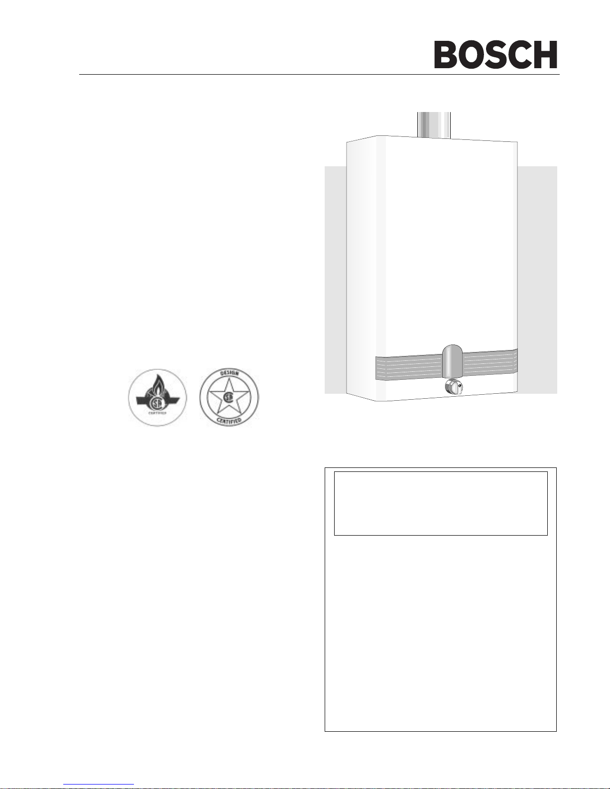
Bosch WR 400-7.K Installation & Operation Manual
6 720 606 560 CA (05.05) AL
ASTRAVAN DISTRIBUTORS, LTD.
123 Charles Street
North Vancouver, B.C. V7H 1S1
Phone Canada: (604) 929-5488
Phone USA: (206) 860-8448
Web Site: www.astravan.com
Note: In case of problems please contact your salesman or installer
NOTICE TO INSTALLER: Please leave this
manual with the owner or affix adjacent to
appliance.
Instantaneous gas water heater
WARNING: If the information in this
manual is not followed exactly, a fire or
explosion may result causing property
damage, personal injury or death.
- Do not store or use gasoline or other flammable vapors and liquids in the vicinity of this or
any other applicance.
- WHAT TO DO IF YOU SMELL GAS
• Do not try to light any appliance.
• Do not touch any electrical switch; do not use
any phone in your building.
• Immediately call your gas supplier from a
neighbor’s phone. Follow the gas supplier’s
instructions.
• If you cannot reach your gas supplier, call the
fire department.
- Installation and service must be performed by
a qualified installer, service agency or the gas
supplier.
READ INSTRUCTIONS CAREFULLY BEFORE INSTALLING
ELECTRONIC IGNITION
Model
WR 400-7.K..
• installation
• operation
• maintenance
The Bosch instantaneous water heater is a high efficiency,
space saving answer to your water heating needs. All Bosch
instantaneous water heaters heat water only as required; no
energy is lost maintaining a large volume of water at elevated
temperatures as in tank-type storage water heaters.
Suitable for heating potable water only – not approved for
space heating purposes.
http://waterheatertimer.org/Troubleshoot-Bosch-Tankless-water-heater.html
2 6 720 606 560
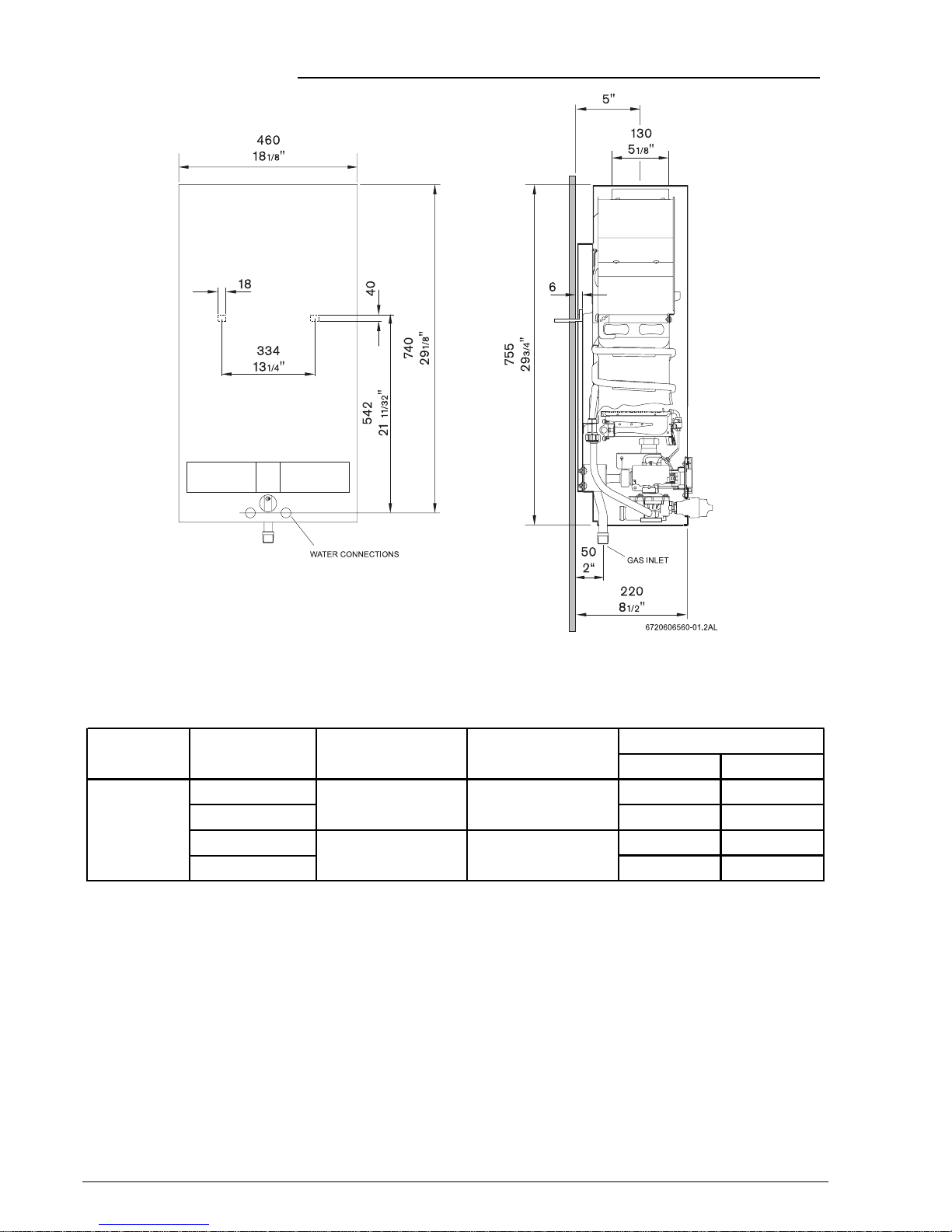
DIMENSIONS
Maximum hydrostatic water pressure - 1.03 MPa (150 p.s.i.)
Maximum recommended working pressure - 0.69 MPa (100 p.s.i.)
Minimum working pressure - 0.0138 MPa (2 p.s.i.) at 2 Litres/min. (0.5 U.S. gals./min.).
* The high altitude ratings listed are Canadian Gas Association high altitude ratings and are valid only in Canada.
In the U.S., the National Fuel Gas Code, ANSI Z223.1-1988, recommends for high altitude installations above 2,000
feet, that the input rate be reduced 4% for each 1,000 feet above sea level. - See page 8.
Figure 1
Size, mm Qt.
natural standart 34.28 kW 1.20 diam. 18
propane/LP (0-2,000 ft.) (117,000 Btu/hr) 0.79 diam. 18
natural high * 30.85 kW 1.20 diam. 18
propane/LP (2,000-4,500 ft.) (105,000 Btu/hr) 0.79 diam. 18
Main Burner Orifices
WR 400-7.K..
Model Type of Gas Altitude Input

36 720 606 560
FORWARD
The design of the WR400-7.K.. complies with CAN 1-4.3
and ANSI Z21.10 (latest edition) as an instantaneous gas
water heater. In addition, the WR400-7.K.. also complies with
CAN 1-2.17 for use at high altitudes, 2.000 – 4.500 ft. above
sea level.
Installation, operation and maintenance information are
provided in this manual. Installation and operation instructions
should be thoroughly reviewed before proceeding with
installation of the BOSCH instantaneous gas water heater.
The BOSCH instantaneous gas water heater is designed to
operate on natural or propane gas; however, make sure that
gas on which heater is to operate is the same as specified
on the heater’s model/rating plate.
In addition to these instrutions,the water heater shall be
installed in accordance with CAN/CGA-B149 Installation
Code (in Canada) or Z223-1- latest edition, National Fuel
Gas Code (in U.S.A.) and/or local installation Code. These
shall be carefully followed in all cases.
Note: Proper plumbing, venting, gas connections and an
adequate supply of combustion air are required for
safe and reliable operation. Ability equivalent to that
of a licensed tradesman in the field involved is required
for installation and/or servicing of these water heaters.
LOCATION
Before installing the BOSCH instantaneous gas water heater
consideration must be given to proper location.
The location should be as close to a chimney or gas vent as
practicable, in an area with an adequate air supply and as
centralized with the piping system as possible. The heater
should not be located in an area where it will be subject to
freezing. The heater should be located in an area where
leakage of the heater or its connections will not result in
damage to the area adjacent to the heater or to lower floors
of the structure.
Note: When such locations cannot be avoided, it is
recommended that a suitable drain pan, adequately
drained, be installed under the water heater. The pan
must not restrict combustion air flow.
AIR REQUIREMENTS
For safe operation, sufficient air for combustion, ventilation
and dilution of flue gases must be available. An insufficient
supply of air will result in a yellow luminous burner flame,
causing carboning or sooting of the heat exchanger.
In order to prevent corrosion, make sure that the combustion
air is kept free of aggressive substances. Substances that
specially contribute to corrosion are halogenated
hydrocarbons (e.g. chlorine and fluorine), which are contained
in solvents, paint, adhesives, propellant gases, various
household cleaners, etc. Take precautionary measures as
necessary.
In unconfined spaces, in buildings of normal construction,
infiltration normally is adequate to provide air for combustion,
ventilation and dilution of flue gases.
However, a confined space must be provided with two
permanent openings to provide combustion and ventilation
air to the appliance. Each opening shall have a free area of
one square inch per 1000 BTU/Hr* of total input rating of all
appliances in the enclosure. One opening shall be within 12
inches of the top and one within 12 inches of the bottom of
the enclosure.
* SPECIAL NOTE
When the WR400-7.K.. is installed in a confined space of
minimum size the openings described above must be
increased to a size of 1½ square inches per 1000 BTU/Hr.
In other words, when installed in a minimum sized confined
space the two openings that are to be made in the enclosure
within 12 inches of the top and 12 inches of the bottom must
each have a minimum free area of, (1½”) x (117)= 175.5 square
inches.
INSTALLATION INSTRUCTIONS

4 6 720 606 560
For either a confined or unconfined space in a building of
tight construction with inadequate infiltration, air must be
drawn from the outdoors or from spaces that freely
communicate with the outdoors. Two permanent openings
located as indicated are to be provided as follows:
1. When communicating with outdoor directly, or by
means of vertical ducts, each opening shall have a
free area of not less than one square inch per 4000
BTU/Hr of total input of all appliances in the space.
2. When communicating with outdoor by means of
horizontal ducts, each opening shall have a free area
of not less than one square inch per 2000 BTU/Hr of
total input of all appliances in the space.
For detailed requirements see:
- in Canada, CAN 1-B 149 Installation Codes
- in U.S.A., ANSI Z223.1- latest edition, National Fuel
Gas Code.
WARNING!
1. Flammable materials, gasoline, pressurized containers,
or any other items or articles that are potentially fire
hazards must never be placed on or adjacent to the
heater. The appliance area must be kept free of all
combustible materials, gasoline and other flammable
vapors and liquids.
2. Do not obstruct the flow of combustion and ventilation
air to the appliance.
CLEARANCE
The WR400-7.K.. is designed certified for installation on a
combustible wall and for installation in an alcove or closet
with minimum clearances to combustible construction of 0
mm from back, 102 mm (4 inches) from sides, 305 mm (12
inches) from top an bottom, and 102 mm (4 inches) from
front. A minimum of 305 mm (12 inches) shall be allowed for
maintenance of serviceable parts. Clearance from vent is
dependant upon the clearance rating of the venting material
used; that is, type B-1 vent is approved for 1 inch clearance,
B-2 vent for 2 inches, etc.
Warning!
Check Flue Gas Safety Device good functioning, please proceed as explained in "Flue gas safety device" page 9.
THIS APPLIANCE MUST BE INSTALLED IN ACCORDANCE WITH THE NATIONAL FUEL GAS CODE
ANSI Z223.1- latest edition in U.S.A. or CAN/CGA- B149 INSTALLATION CODES IN CANADA, LOCAL
CODES AND/OR THE REQUIREMENTS OF THE AUTHORITY HAVING JURISDICTION MUST BE
FOLLOWED.
MOUNTING
The WR400-7.K.. is designed certified for mounting to a wall.
The heater must not be installed on a carpeted wall. The
heater must be mounted to the wall using appropriate
anchoring materials.
Note: If wall is a stud wall sheathed with plasterboard it is
recommended that support board(s), either 1x4’s or
½‘’ (minimum) plywood first be attached across a pair
of studs and then the heaters should be attached to
the support boards. See Figure2.
Figure 2
Expansion and contraction of piping due to changing water
temperature in the pipes imparts movement to the heater
which, if mounted directly to a brittle, friable board, such as
plasterboard, can cause failure of mounting.
WALL STUDS
1” X 4”
SPACE BOARD
SUPPORT BOARD
56 720 606 560
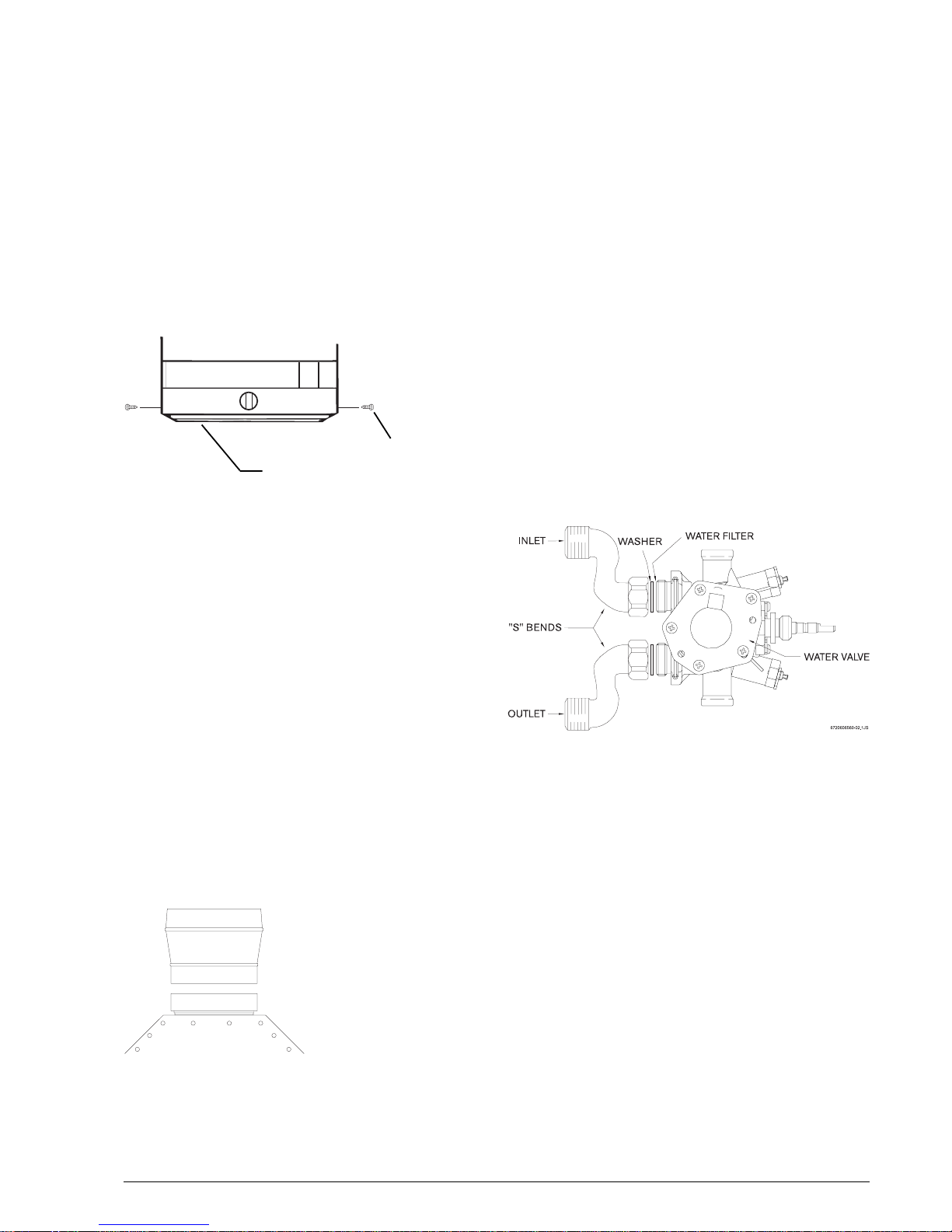
DRIP TRAY
If the water heater is being mounted above a floor of
combustible construction the drip tray (shipped loose in the
carton with the water heater) must be attached to the bottom
of the front cover of the water heater at the time of installation.
The drip tray should be attached to the front cover, using
screws provided, as shown in Figure 3.
Failure to use drip tray when installing unit above a floor of
combustible construction will cause an unsafe condition and
possible fire and will be in violation of A.G.A and C.G.A.
certification of the unit.
Figure 3
VENTING
The BOSCH instantaneous water heaters have built- in draft
diverters and are designed for indoor installation only. The
draft diverter outlet must be connected to a clear,
unobstructed vent of the same size, or lager, refer to:
- in Canada, CAN/CGA – B149 Installation Code for
detailed requirements.
- In U.S.A., ANSI Z223.1- latest edition, National Fuel
Gas Code for detailed requirements.
The flue connection for the WR 400-7.K.. is 130mm (5
inches); however, in Canada for installation at high altitude
(2.000-4.500 ft, above sea level) a six inch (6’’) flue is
required, in Canada a 5’’x 6’’ adapter is required with the
WR400-3.K.. high altitude installations.
Figure 4
For high altitude use the adapter must be installed as shown
in Figure 4, without alteration, before connecting the six inch
flue to the unit. The adapter must be secured to the draft
diverter outlet with a minimum of two screws.
Also, in Canada, the gas pressure regulator supplied with
the water heater is factory preset to deliver gas to the water
heater at the proper pressure setting for high altitude
operation, see PRESSURE REGULATION section of this
manual, table 1 on page 8.
WARNING!
Failure to increase vent size on WR400-7.K.. to six inches
and/or to assure that manifold is set to proper value listed
on rating plate for applications at altitudes in range 2.000 to
4.500 ft. above sea level will cause unsafe venting,
asphyxiation, and voids C.G.A. certification.
WATER CONNECTIONS
The BOSCH instantaneous water heaters are provided with
two S-bend water connectors/adapters that must be
connected to inlet and outlet connections on water valve
assembly, see figure 5 below.
Figure 5
The purpose of the S-bend water connectors/adapters is to
provide threaded water connections that meet standards
used in North America, ANSI Standard Taper Pipe Thread
(1 ½“ NPT).
The cold water should be connected to S-bend attached to
inlet of water valve and hot water connection should be made
to S-bend attached to outlet of water valve.
If plastic piping is to be used, a 1.5 meter (approx. 5 feet)
length of metal piping must first be attached to both the cold
water inlet and hot water outlet of the water heater.
Note: A shut-off valve should be placed in the cold water
supply line to the heater to facilitate servicing the
heater.
SCREWS
INCANDESCENT PARTICLE TRAY
5” X 6” ADAPTOR
USED ON HIGH ALTITUDE
 Loading...