

Bosch WR11B, WR14B, WR18B Installation Manual And Operating Instructions
Installation Manual and Operating Instructions
Gas Instantaneous Water Heater
WR 11/14/18 .B..
6 720 648 592 (2011/06) ZA
Read installation manual prior to installation of this unit!
Read user manual before putting this unit in operation!
Observe the warnings in the manuals!
The installation room must fulfill the ventilation requirements!
Installation by an authorised person only!

2 | Table of contents
6 720 648 592 (2011/06)
Table of contents
1 Key to symbols and safety instructions 3
1.1 Explanation of symbols 3
1.2 Safety Instructions 3
2 Technical Characteristics and Dimensions 5
2.1 Declaration of conformity with relevant EEC
regulations 5
2.2 Explanation of Model Code 5
2.3 Accessories (Included with Appliance) 5
2.4 Description of the heater 5
2.5 Explanation of model code 5
2.6 Special accessories 6
2.7 Dimensions 6
2.8 Functional diagram of the heater 7
2.9 Electrical diagram 8
2.10 Function 8
2.11 Technical characteristics 9
3Use 10
3.1 Before starting up the heater 10
3.2 Batteries 10
3.3 Turning the heater on and off 10
3.4 Power adjustment 11
3.5 Temperature/flow adjustment 11
3.6 Purge the appliance 11
3.7 Cleaning 11
4Regulation 12
5 Installation (must be carried out only by
qualified technicians) 13
5.1 Important information 13
5.2 Selection of the place of installation 13
5.3 Heater mounting 14
5.4 Water connection 14
5.5 Gas connection 14
5.6 Inlet/exhaust pipe installation 15
5.7 Startup 15
6 Adjustments (must be carried out only by
qualified technicians) 16
6.1 Factory regulations 16
6.2 Pressure adjustment 16
6.3 Conversion to a different type of gas 17
7 Maintenance (must be carried out only by
qualified technicians) 18
7.1 Periodic maintenance work 18
7.2 Startup after maintenance work 18
7.3 Flue gas safety device 18
8Problems 20
9 Environment / disposal 21
Key to symbols and safety instructions | 3
6 720 648 592 (2011/06)
1 Key to symbols and safety instructions
1.1 Explanation of symbols
Warnings
Keywords indicate the seriousness of the hazard in
terms of the consequences of not following the safety
instructions.
• NOTE indicates that material damage may occur.
• CAUTION indicates that minor to medium injury may
occur.
• WARNING indicates that serious injury may occur.
• DANGER indicates possible risk to life.
Important information
Additional symbols
1.2 Safety Instructions
If there is a smell of gas:
B Close the gas valve.
B Open windows.
B Do not operate any electrical appliances or switches
(on/off).
B Extinguish any naked flames.
B Phone the gas company or an authorized technician
from a safe distance.
If there is a smell of burnt gases:
B Disconnect the appliance.
B Open doors and windows.
B Inform an installation company.
Burn-back (fire in burner tube or chamber)
B In the event of a burn-back, where the flame burns
back to the injector, immediately turn off the gas
supply at the control valve on the panel.
B After ensuring the flame is extinguished, wait for one
minute and re-light the appliance in the normal
manner.
B Should the appliance again burn back, close the
control valve and call a service technician.
B Do not use the appliance again until the service
technician has declared that it is safe to do so.
Fitting, modifications
B The fitting and modification of the installation of the
appliance must be carried out only by an authorized
technician.
B The installation of the water heater may only be
carried out by a registered installer and that such
installations shall comply with the requirements of
SANS 10087-1.
B The pipes carrying burnt gases must not be modified.
B Do not close or reduce air circulation holes.
Maintenance
B We reccomend to have the system regularly serviced
in order to ensure that it functions reliably and safely.
B The installer is responsible for the safety and
environmental compatibility of the installation.
B The appliance should be serviced annually.
B Only original spare parts must be used.
Warnings in this document are framed and
identified by a warning triangle which is
printed on a grey background.
Electrical hazards are identified by a
lightning symbol surrounded by a warning
triangle.
Important information in cases where there
is no risk of injury or material losses is
identified by the symbol shown on the left.
It is bordered by horizontal lines above and
below the text.
Symbol Meaning
B a step in an action sequence
Æ a reference to a related part in the
document or to other related documents
•a list entry
– a list entry (second level)
Table 1

4 | Key to symbols and safety instructions
6 720 648 592 (2011/06)
Explosive and inflammable materials
B Inflammable materials (paper, solvents, ink, etc.)
should not be stored near the appliance.
Combustion air and ambient air
B To avoid corrosion, combustion air and ambient air
should be free of aggressive substances (for example
halogenated hydrocarbons containing chlorine and
fluoride composites).
Important information for the user
B This appliance may only be installed by a registered
LP Gas installer.
B All registered installers are issued with a card carrying
their registration number.
B Ask to be shown the card before allowing the
installation work to commence and make a note of the
Installer QCC number. Upon completion of the
installation, the installer is required to explain the
operational details of the appliance together with the
safety instructions. You will be asked to sign
acceptance of the installation and be provided with a
completion certificate. You should only sign for
acceptance of the installation when the installation is
completed to your satisfaction.
B Note that your invoice is required in the event that you
wish make a guarantee claim.
Important information for the installer
B This appliance may only be installed by a LP gas
installer registered with the Liquefied Petroleum Gas
Association of Southern Africa.
B The appliance must be installed in accordance with
the requirements of SANS 10087-1 and any fire
department regulations and/or local by laws
applicable to the area. If in doubt check with the
relevant authority before undertaking the installation.
B Upon completion of the installation you are required
to fully explain and demonstrate to the user the
operational details and safety practices applicable to
the appliance and the installation.
Client information
B Inform the client about the function and operation of
the appliance.
B Caution clients against performing modifications or
repairs themselves.
Risk of damage due to operator error
Operator errors can result in injury and damage to
property.
B Ensure that children never operate this appliance
unsupervised or play with it.
B Ensure that only personnel who can operate this
appliance correctly have access to it.
Technical Characteristics and Dimensions | 5
6 720 648 592 (2011/06)
2 Technical Characteristics and Dimensions
2.1 Declaration of conformity with
relevant EEC regulations
This appliance fulfills European directive requirements
2009/142/EC, 2006/95/EC, 2004/108/EC and
corresponds to the specifications described in the
corresponding EEC certificate of proof.
2.2 Explanation of Model Code
W Gas Water Heater
R Proportional power adjustment
11 Capacity (l/min)
B Electronic ignition powered by 1.5 V batteries
23 Indicator number of natural gas H
31 Indicator number of LPG
S... Country code
The code number indicates the gas group according to
EN 437:
2.3 Accessories (Included with Appliance)
•Gas water heater,
• Attachment elements,
• Installation accessories,
• Two 1.5 V batteries type R
•Heater documentation.
2.4 Description of the heater
Operating convenience, as the heater is ready to operate
by simply pressing a switch.
• Heater for wall-mounting,
• Ignition by electronic device triggered when the water
valve opens,
• Great savings in comparison with conventional
heaters, due to the possibility of power adjustment
and no permanent pilot flame,
• Natural gas/LPG burner,
• Semi-permanent pilot burner which only functions
during the period between the opening of the water
valve and the ignition of the main burner,
• Heat exchanger in copper without tin/lead covering,
• Water valve in fibreglass-reinforced polyamide, 100%
recyclable,
• Automatic adjustment of the water flow by means of
a device which permits a constant flow to be
maintained in spite of variable pressure supplies,
• Gas flow adjustment proportional to the water flow to
maintain a constant high temperature.
•Safety devices:
– Ionisation probe to check for accidental extinction
of the burner flame,
– Flue gas safety device which turns off the heater in
case of inadequate combusted gas evacuation
conditions,
– Temperature limiter which prevents overheating of
the heat exchanger.
2.5 Explanation of model code
The type plate is located at the bottom left of the
appliance.
There you will find details of appliance output, model
number, approval data and the serial number.
Model WR 11/14/18 B...
Category II
2H3+
Type Type B
Table 2
W R 11 B 23
31
S....
W R 14 B 23
31
S....
W R 18 B 23
31
S....
Table 3
Identification
Code
Wobbe Index
(Ws) (15 °C)
Gas type
23
12,7-15,2
kWh/m
3
Natural Gas Group H
31
20,2-21,3
kWh/m
3
LPG - Group B/P
Table 4
6 | Technical Characteristics and Dimensions
6 720 648 592 (2011/06)
2.6 Special accessories
• Conversion kit from natural gas to butane/propane.
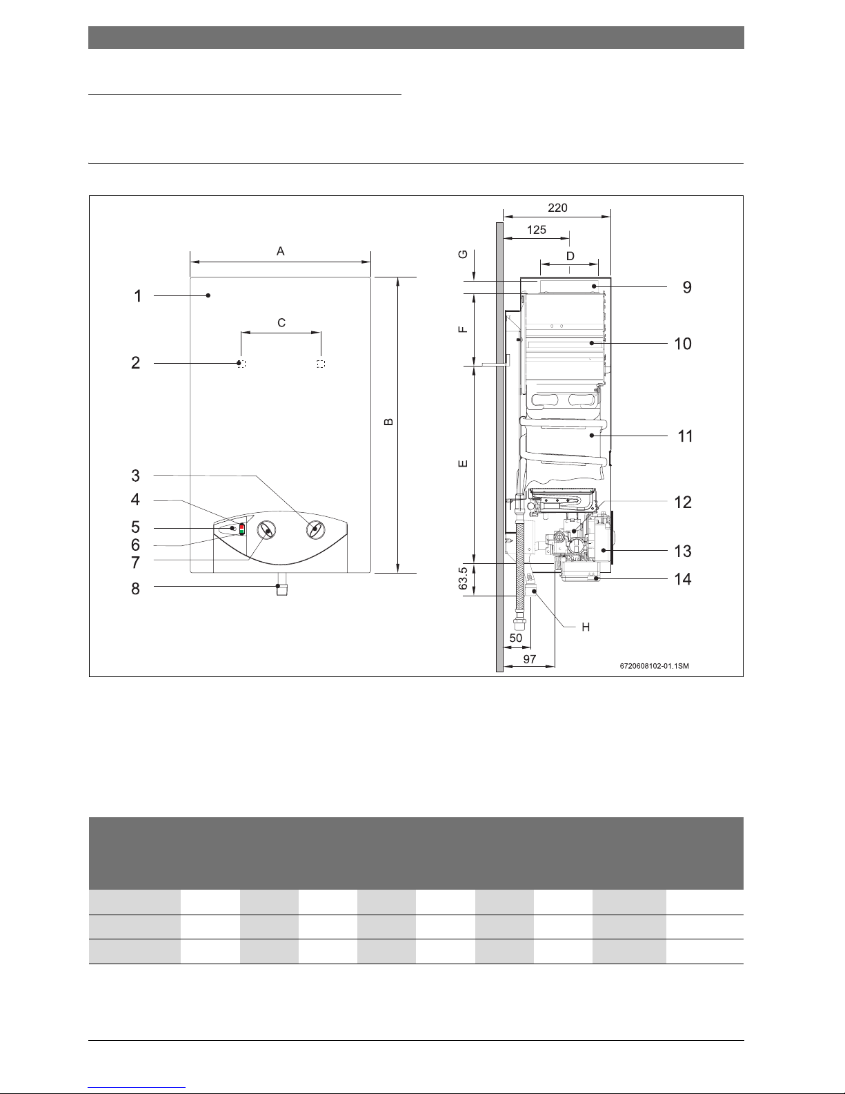
2.7 Dimensions
Fig. 1
1 Front cover
2 Hole for fixing to wall
3 Temperature control
4 Led indicator for battery charge level
5 ON/OFF switch
6 Led indicator for burner status
7 Output control
8 Gas connection
9 Flue socket
10 Draught diverter with flue gas monitor
11 Heat exchanger
12 Automatic gas valve
13 Igniter unit
14 Battery compartment
Dimensions
(mm)
A B C D E F G
H (Ø)
Natural
gas
LPG
WR11B 310 580 228 112,5 463 60 25 1/2” 1/2”
WR14B 350 655 228 132,5 510 95 30 1/2” 1/2”
WR18B 425 655 334 132,5 540 65 30 1/2” 1/2”
Table 5 Dimensions
Technical Characteristics and Dimensions | 7
6 720 648 592 (2011/06)
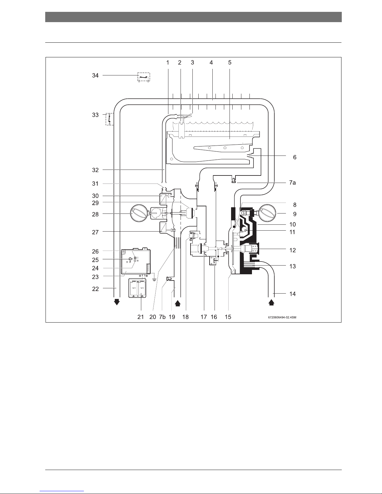
2.8 Functional diagram of the heater
Fig. 2 Functional diagram
1 Pilot burner
2 Igniter electrode
3 Ionisation detector
4 Heat exchanger
5 Main burner
6 Injector
7a Testing point for burner pressure
7b Testing point for supply pressure
8 Venturi
9 Temperature/volume selector
10 Water valve
11 Adjusting screw for min. water flow rate
12 Water flow regulator
13 Water filter
14 Cold water supply pipe
15 Diaphragm
16 Microswitch
17 Main gas valve
18 Regulating screw
19 Gas inlet
20 Gas filter
21 Battery compartment
22 Hot water pipe
23 Igniter unit
24 Led indicator for burner status
25 ON/OFF switch
26 Led indicator for battery charge level
27 Servo valve
28 Output control
29 Gas valve
30 Gas valve for pilot burner
31 Pilot burner injector
32 Gas pipe for pilot burner
33 Temperature limiter
34 Flue gas safety device
8 | Technical Characteristics and Dimensions
6 720 648 592 (2011/06)
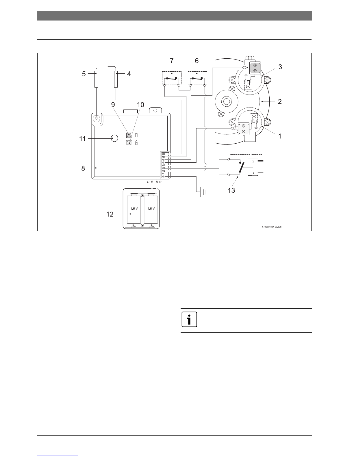
2.9 Electrical diagram
Fig. 3 Electrical diagram
1 Servo valve (normally open)
2 Diaphragm valve
3 Main valve (normally closed)
4 Ionisation detector
5 Igniter electrode
6 Flue gas safety device
7 Temperature limiter
8 Igniter unit
9 LED indicator for battery charge level
10 LED indicator for burner status
11 ON/OFF switch
12 Batteries, 1.5V
13 Microswitch
2.10 Function
This gas heater is equipped with automatic electronic
ignition which simplifies its operation.
B To do so, just turn on the switch (ÆFig. 6).
After this procedure, automatic ignition occurs
whenever a hot water tap is opened. First, the pilot
burner is lit and approximately four seconds afterwards
the main burner. The pilot burner flame is then
extinguished after a short period of time.
This is a way of saving a great amount of energy as the
pilot burner only operates for the minimum necessary
time to ignite the main burner, in contrast to
conventional systems which operate permanently.
If this happens:
B Close and open the hot water tap to repeat the
ignition process until all the air has been purged.
Air in the gas supply pipe when the heater is
started up may cause ignition to fail.
 Loading...