

Bosch WR10**B, WR11**B Installation And Operating Instructions Manual
6 720 607 823 GB (06.06) SM
WR10..B...
WR11..B...
With electronic ignition and triple safety system
consisting of ionisation detector, flue gas monitor
and heat exchanger temperature sensor.
Safety instructions:
If you smell gas:
- Do not operate any electrical switches.
- Do not telephone from inside the danger area.
- Turn off the gas cock.
- Open windows and ventilate room.
- From outside, call the gas company and your approved
installer.
Do not use or store easily combustible materials in the vicinity
of the appliance.
Gas Instantaneous Water Heater
Installation and Operating Instructions
Installation and servicing of the appliance may only be
carried out by an approved technician.
The appliance should be regularly serviced in order to ensure
that it remains in perfect and safe working order.
If there is a risk of freezing, the appliance must be switched
off and drained. If the appliance has not been drained during
a cold spell, when it is switched on again check that it
produces hot water. If problems occur, contact your installer
2 6 720 607 823
2.5 Gas connection ................................................................. 5
2.6 Flue....................................................................................... 5
2.7 Commissioning .................................................................. 6
3. Operation and maintenance
3.1 Function .............................................................................. 6
3.2 Water temperature control .............................................. 6
3.3 Appliance adjustments ..................................................... 6
3.4 Maintenance ...................................................................... 6
3.5 Purge the appliance ......................................................... 6
3.6 Flue gas safety device ..................................................... 6
3.7 Converting to a different gas type ................................ 7
3.8 Troubleshooting ................................................................. 7
4. Operation .................................................................................. 8
1. Technical Characteristics and Dimensions
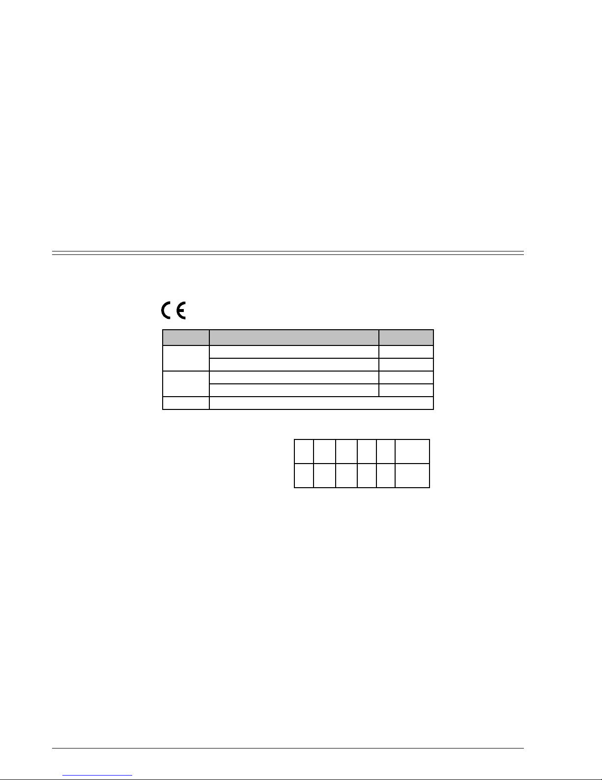
1.1 Category, Appliance Type and Approval Number
1.2 General Description
The appliance is easy to operate as it is ready to use at the
press of a button.
Guaranteed safety provided by:
- Gas-tight ionisation detector that prevents escape of gas
if there is no flame.
- Flue gas safety device that switches off the appliance if
the flue is not functioning properly.
- Temperature limiter which protects the heat exchanger
against overheating.
Electronic ignition controlled by opening of water valve.
Absence of a permanent pilot flame make it more
economical than conventional appliances.
Semi-permanent pilot flame functions only during the time
between opening of the water valve and activation of the
main burner.
Heat exchanger has no tin/lead lining.
Automatic water valve made of glass-fibre reinforced
polyamide, 100% recyclable.
Automatic control of water flow maintains constant flow rate
even with fluctuating supply pressure.
Proportional adjustment of gas and water flow rates in order
to ensure an even temperature gradient.
Green LED indicates burner condition.
1.3 Explanation of Model Code
Contents
W Gas instantaneous water heater
R Proportional output control
10 Flow rate (l/min)
B Electronic ignition powered by 1.5 V batteries
23 Natural gas type H
31 LPG (butane/propane)
S... Country code
1. Technical Characteristics and Dimensions
1.1 Category, Appliance Type and Approval Number ...... 2
1.2 General Description ......................................................... 2
1.3 Explanation of Model Code ............................................ 2
1.4 Dimensions ......................................................................... 3
1.5 Appliance design ............................................................... 3
1.6 Circuit diagram .................................................................. 4
1.7 Technical characteristics ................................................. 4
2. Preconditions for installation
2.1 Regulations ......................................................................... 5
2.2 Location .............................................................................. 5
2.3 Fixing the appliance.......................................................... 5
2.4 Water connection ............................................................. 5
0464 BQ 20
W R 10 B 23 S…
W R 11 B 31 S…
MODEL CATEGORY
CH, ES, GB, IT, PT, HR
I
2H
BE, FR, LU
I2E+
BE, CH, ES, FR, GB, IT, PT, LU, HR
I
3+
NL, DE
I
3B/P
TYPE
WR10
WR11
B
11BS
36 720 607 823
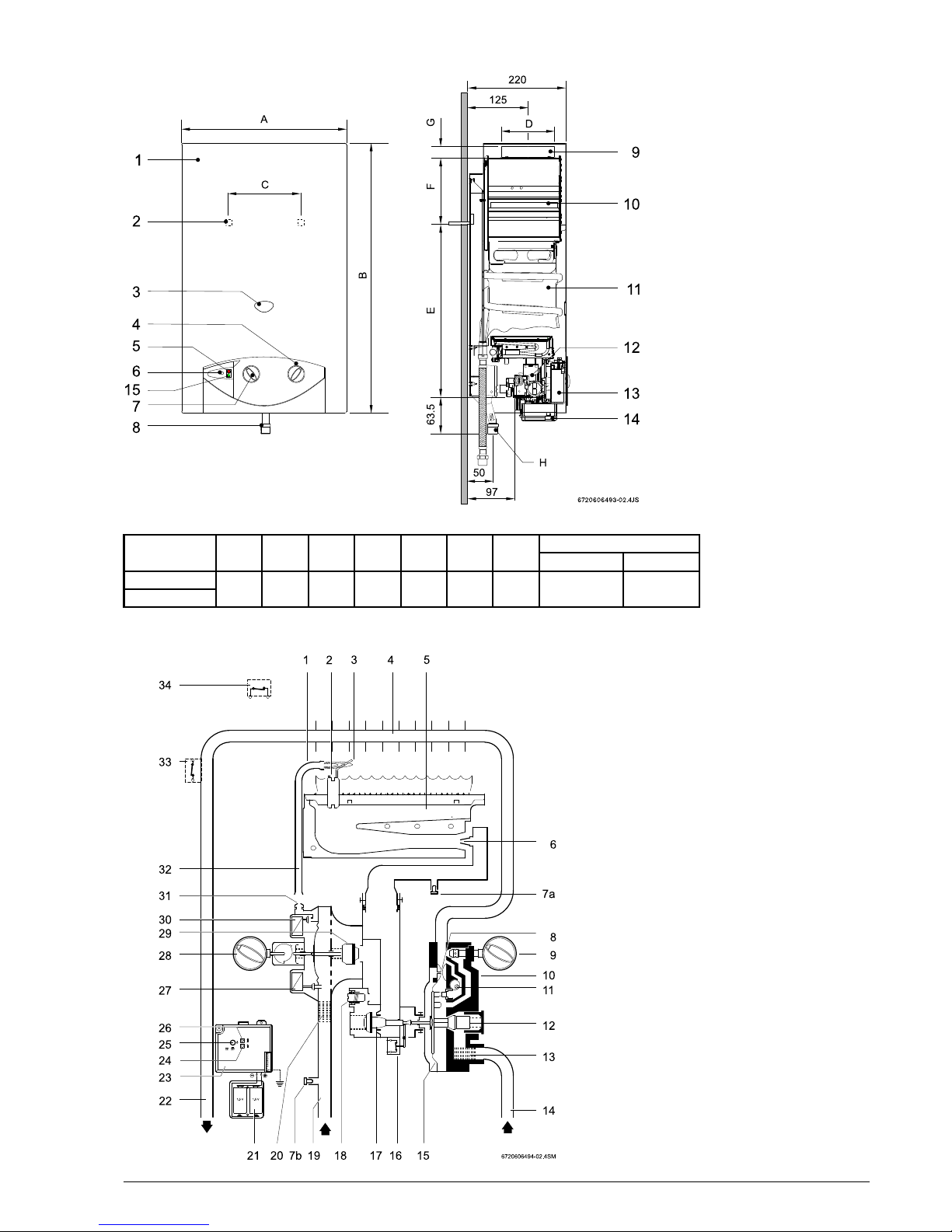
1.4 Dimensions
Fig. 2
1.5 Appliance design
Fig. 3
1. Pilot burner
2. Igniter electrode
3. Ionisation detector
4. Heat exchanger
5. Main burner
6. Injector
7a. Testing point for burner pressure
7b. Testing point for supply pressure
8. Venturi
9. Temperature control
10. Water valve
11. Adjusting screw for min. water flow rate
12. Flow restrictor
13. Water filter
14. Cold water supply pipe
15. Diaphragm
16. Microswitch
17. Main gas valve
18. Regulating screw
19. Gas inlet
20. Gas filter
21. Battery compartment
22. Hot water pipe
23. Igniter unit
24. LED indicator for burner status
25. On/Off switch
26. LED indicator for battery charge level
27. Servo valve
28. Output control
29. Gas valve
30. Gas valve for pilot burner
31. Pilot burner injector
32. Pilot burner pipe
33. Temperature limiter
34. Flue gas safety device
1. Front cover
2. Hole for fixing to wall
3. Observation window
4. Temperature control
5. LED indicator for battery
charge level
6. On/Off switch
7. Output control
8. Gas connection
9. Flue socket
10. Draught diverter with flue
gas monitor
11. Heat exchanger
12. Automatic gas valve
13. Igniter unit
14. Battery compartment
15. LED indicator for burner
status
Dimensions A B C D E F G
(mm) Natural Gas LPG
WR10..B...
WR11..B...
H (Ø)
580310 60463112,5228 25 3/4" 1/2"
 Loading...