

Page 1
AutoDome Junior
VJR-A3-IC
en Installation Manual
Page 2

Page 3

AutoDome Junior Table of Contents | en 3
Table of Contents
1 Installing a Recessed Mount 4
1.1 Description 4
1.1.1 Additional Requirements 4
1.1.2 Preparing the Ceiling for Installation 5
1.1.3 Installing the Camera to the Mounting Plate 8
Bosch Security Systems, Inc. Installation Manual F.01U.168.034 | 3.0 | 2010.12
Page 4
4 en | Installing a Recessed Mount AutoDome Junior
1 Installing a Recessed Mount
1.1 Description
This chapter details how to recess mount the AutoDome Junior.
NOTICE!
The image sensors in modern CCD cameras are highly sensitive
and require special care for proper performance and extended
lifetime. Follow the guidelines for optimum results with your
camera:
– Do not expose to direct sunlight or bright spotlights in
operating and nonoperating conditions.
– Avoid bright lights in the field of view of the camera. Bright
lights cause a “smearing” effect, which is visible as white
lines above and below the highlight. Prolonged exposure to
bright lights may cause bleaching of the sensor's color
filters. This will be visible as colored spots in the picture
and is irreversible.
1.1.1 Additional Requirements
– Appropriate straight slot screwdrivers
– No. 2 Phillips screwdriver
– Appropriate tool for cutting a hole in drywall or ceiling tile
(if applicable)
– 4 in. x 4 in. junction box (optional)
– T-10 Torx wrench
– VJR-A3-SP, support kit for VJR-A3-IC mounting kit
F.01U.168.034 | 3.0 | 2010.12 Installation Manual Bosch Security Systems, Inc.
Page 5
AutoDome Junior Installing a Recessed Mount | en 5
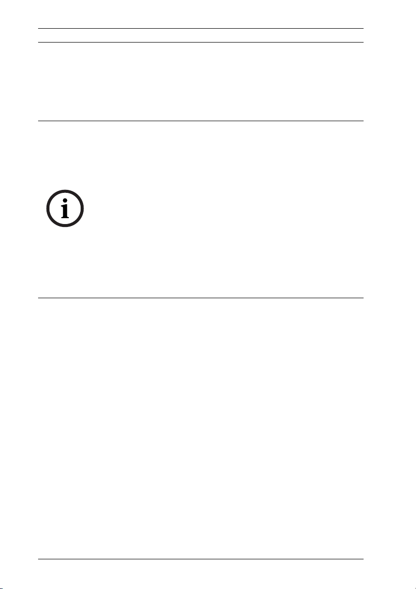
104.9
(4.13)
71.6
(2.82)
mm
(in.)
229.0
(9.02)
1.1.2 Preparing the Ceiling for Installation
To mount to a recess mount, do the following:
1. Determine a secure location for the recessed mount
(supplied separately).
Figure 1.1 Recess Mount Dimensions
2. Drill or cut a 200 mm hole with a tolerance of 2.2 mm ( 7.9
in. ± 1/8).
3. Optional: if installing the AutoDome Junior HD to a
suspended ceiling tile or any other surface where
additional support is required, the VJR-A3-SP mounting kit
is recommended (supplied separately).
Bosch Security Systems, Inc. Installation Manual F.01U.168.034 | 3.0 | 2010.12
Page 6

6 en | Installing a Recessed Mount AutoDome Junior
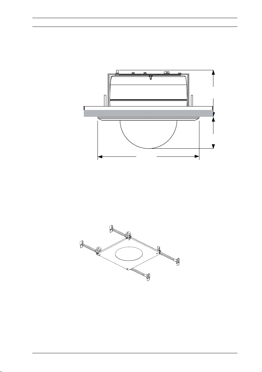
4. Align holes of mounting plate (supplied with dome) with
mounting bracket and attach with screws. Ensure that
both the crescent shape of the mounting plate and the
crescent shape of the mounting bracket are aligned.
Figure 1.2 Attach Mounting Plate to Mounting Bracket
1 Mounting Bracket
2 Mounting Plate
3 Clamping Plate
4 Crescent Shape
5 Clamp Drive Screw
5. Loosen the two clamp drive screws (item 5, above) so that
the clamping plates move freely.
6. Insert mount through the hole in the ceiling. Slide clamps
out and down so that the ceiling/drywall is captured in
between the clamps and the bracket flange. The ceiling/
drywall must have a maximum thickness of 41.7 mm
(1.64 in.) and an minimum thickness of 12.7 mm (0.50 in.).
F.01U.168.034 | 3.0 | 2010.12 Installation Manual Bosch Security Systems, Inc.
Page 7

AutoDome Junior Installing a Recessed Mount | en 7
Figure 1.3 Attach Recess Mount to Ceiling
7. Tighten both clamps using the clamp drive screws
(installed on the assembly) and a #2 Phillips screwdriver.
NOTICE!
Over-torquing the ceiling clamps can damage the clamp or
ceiling. Only tighten the clamp until it contacts the ceiling and
you start to feel some resistance. If using a power screwdriver,
set the torque level to the lowest setting.
NOTICE!
If you need to install the the VJR-A3-SP Support Bracket, refer
to the guide included with the bracket. Once the bracket is
installed, continue with the next section.
Bosch Security Systems, Inc. Installation Manual F.01U.168.034 | 3.0 | 2010.12
Page 8

8 en | Installing a Recessed Mount AutoDome Junior
1.1.3 Installing the Camera to the Mounting Plate
To install the base to a surface or suspended ceiling using the
supplied mounting plate, do the following:
1. Loosen the single safety locking screw on the base of the
unit using the user-supplied T-10 Torx wrench.
Figure 1.4 Unlock Safety Locking Screw
CAUTION!
All wires for installation applications must be routed through a
grounded conduit.
2. Remove the screw from the Earth ground ( )on the top
of the mounting bracket.
3. Attach a user-supplied ground wire to the Earth ground
( ) screw hole on the mounting bracket and secure with
the screw.
4. Attach the green grounding wire from the unit to the
grounded ( ) screw hole on the mounting bracket using
the attached captive screw washer.
5. Route wires on the side of mounting plate with the
crescent shaped cut-out.
6. Connect the mating connectors (supplied in the accessory
kit) with the flying leads to the user supplied wiring.
F.01U.168.034 | 3.0 | 2010.12 Installation Manual Bosch Security Systems, Inc.
Page 9

AutoDome Junior Installing a Recessed Mount | en 9
7. Plug the matching connectors from the camera into the
mating connectors from the ceiling.
Figure 1.5 Match Connectors
1 Locking Screw
2 Crescent Shape
3 Mounting Plate
4 Vertical Tab
Bosch Security Systems, Inc. Installation Manual F.01U.168.034 | 3.0 | 2010.12
Page 10

10 en | Installing a Recessed Mount AutoDome Junior
8. Attach the camera to the mounting plate by inserting the
vertical tab on the plate (item 1, below) into the recessed
slot on the top of the camera dome (Item 3) to the right of
the safety locking screw (item 2).
Note: Do not loosen the three brass buttons (item 4).
These brass buttons engage the slotted tabs (item 5) on
the mounting plate.
Figure 1.6 Tab/Slot Alignment Detail
1 Vertical Tab (on mounting plate)
2 Locking Screw
3 Recessed Slot (on dome housing)
4 Brass Button (total of three on housing)
5 Slotted Tab (total of three on mounting plate)
F.01U.168.034 | 3.0 | 2010.12 Installation Manual Bosch Security Systems, Inc.
Page 11

AutoDome Junior Installing a Recessed Mount | en 11
9. Rotate the camera approximately 15 degrees in the
clockwise direction. Then, lock firmly into place, as shown
in the next illustration.
Figure 1.7 Attach Dome to Mounting Plate
1 Recess Mounting Bracket
2 Mounting Plate
3 Mounting Bracket Tether Point
10. Ensure unit is centered.
NOTICE!
The recessed mounting bracket is provided with an additional
safety tether point. To prevent injury, attach a safety wire from
a secure anchor point above the ceiling to this tether point.
Bosch Security Systems, Inc. Installation Manual F.01U.168.034 | 3.0 | 2010.12
Page 12

12 en | Installing a Recessed Mount AutoDome Junior
11. Align trim ring so the four alignment posts (item 1, below)
align with the recesses in the camera housing (item 2) and
so the two safety screws align with the off center holes
(item 3) on the locking clamps.
Note: The two (2) sets of raised stand-off tabs (item 4) on
each side of the trim ring align with the locking clamps.
Figure 1.8 Align Trim Ring
1 Alignment Tabs (four)
2 Align tabs to the recessed areas on the housing
3 Align safety locking screws to these connections
4 Stand-off Tabs (two)
12. Snap trim ring into place. Ensure snaps are secure by
attempting to lightly turn unit. Note: Unit should not turn.
13. Use the supplied T-10 Torx wrench to secure the trim
ring’s two (2) safety locking screws to the mounting
bracket.
F.01U.168.034 | 3.0 | 2010.12 Installation Manual Bosch Security Systems, Inc.
Page 13

Page 14

Bosch Security Systems, Inc.
850 Greenfield Road
Lancaster, PA 17601
U.S.A.
www.boschsecurity.com
© Bosch Security Systems, Inc., 2011
 Loading...