

Bosch VIP X1600 M4S User Manual
VIP X1600 M4S
Encoder module
en Installation and Operating Manual

VIP X1600 XFM4

VIP X1600 Table of Contents | en 3
Table of Contents
1Preface 7
1.1 About this Manual 7
1.2 Conventions in this Manual 7
1.3 Intended Use 7
1.4 EU Directives 8
1.5 Rating Plate 8
2 Safety Information 9
2.1 Electric Shock Hazard 9
2.2 Installation and Operation 9
2.3 Maintenance and Repair 9
3 Product Description 11
3.1 Scope of Delivery 11
3.2 System Requirements 11
3.3 Overview of Functions 12
3.4 Connections 15
4 Installation 17
4.1 Preparations 17
4.2 Installing Modules 17
4.3 Connections 19
4.4 Setup Using the Configuration Manager 21
5 Configuration Using a Web Browser 23
5.1 Connecting 23
5.2 Configuration Menu 25
5.3 Basic Mode: Unit Access 27
5.4 Basic Mode: Date/Time 28
5.5 Basic Mode: Network 29
5.6 Basic Mode: Encoder Profile 30
5.7 Basic Mode: Audio (Audio Version Only) 31
5.8 Basic Mode: Recording 31
5.9 Basic Mode: System Overview 32
5.10 Advanced Mode: Identification 33
5.11 Advanced Mode: Password 35
5.12 Advanced Mode: Date/Time 36
5.13 Advanced Mode: Display Stamping 37
5.14 Advanced Mode: Appearance 38
5.15 Advanced Mode: LIVEPAGE Functions 40
5.16 Advanced Mode: Logging 41
5.17 Advanced Mode: Video Input 42
5.18 Advanced Mode: Picture Settings 43
5.19 Advanced Mode: Encoder Profile 44
5.20 Advanced Mode: Audio (Audio Version Only) 47
Bosch Security Systems Installation and Operating Manual DOC | V4.0 | 2009.06

4 de | Table of Contents VIP X1600
5.21 Advanced Mode: Storage Management 48
5.22 Advanced Mode: Recording Profiles 50
5.23 Advanced Mode: Retention Time 52
5.24 Advanced Mode: Recording Scheduler 53
5.25 Advanced Mode: Recording Status 55
5.26 Advanced Mode: Alarm Connections 56
5.27 Advanced Mode: VCA 59
5.28 Advanced Mode: VCA Profiles 60
5.29 Advanced Mode: VCA Scheduled 64
5.30 Advanced Mode: VCA Event Triggered 66
5.31 Advanced Mode: Audio Alarm 67
5.32 Advanced Mode: Alarm E-Mail 68
5.33 Advanced Mode: Alarm Task Editor 70
5.34 Advanced Mode: Alarm Inputs 71
5.35 Advanced Mode: Relay 71
5.36 Advanced Mode: COM1 72
5.37 Advanced Mode: Network 74
5.38 Advanced Mode: Advanced 77
5.39 Advanced Mode: Switch Configuration 79
5.40 Advanced Mode: Multicasting 81
5.41 Advanced Mode: JPEG Posting 82
5.42 Advanced Mode: Encryption 83
5.43 Advanced Mode: Maintenance 84
5.44 Advanced Mode: Licenses 86
5.45 Advanced Mode: System Status 86
5.46 Advanced Mode: System Overview 87
5.47 Function Test 88
6Operation 89
6.1 Operation with Microsoft Internet Explorer 89
6.2 The LIVEPAGE 91
6.3 Saving Snapshots 93
6.4 Recording Video Sequences 94
6.5 Running Recording Program 94
6.6 The RECORDINGS Page 95
6.7 Installing the Player 97
6.8 Hardware Connections Between Video Servers 98
6.9 Operation Using Software Decoders 99
7 Maintenance and Upgrades 101
7.1 Testing the Network Connection 101
7.2 Unit Reset 101
7.3 Repairs 102
7.4 Transfer and Disposal 102
8 Appendix 103
8.1 Troubleshooting 103
8.2 General Malfunctions 104
8.3 Malfunctions with iSCSI Connections 106
DOC | V4.0 | 2009.06 Installation and Operating Manual Bosch Security Systems

VIP X1600 Table of Contents | en 5
8.4 LEDs 106
8.5 Processor Load 107
8.6 Network Connection 107
8.7 Serial interface 107
8.8 Terminal Block 107
8.9 Communication with Terminal Program 109
8.10 Copyrights 111
9 Specifications 113
9.1 VIP X1600 M4S Encoder Module 113
9.2 Protocols/Standards 113
9.3 Image Refresh Rate 114
10 Glossary 115
11 Index 119
Bosch Security Systems Installation and Operating Manual DOC | V4.0 | 2009.06

6 de | Table of Contents VIP X1600
DOC | V4.0 | 2009.06 Installation and Operating Manual Bosch Security Systems
VIP X1600 M4S Preface | en 7
!
i
1Preface
1.1 About this Manual
This manual is intended for persons responsible for the installation and operation of the
VIP X1600 XF. International, national and any regional electrical engineering regulations must
be followed at all times. Relevant knowledge of network technology is required. The manual
describes the installation and operation of the unit.
1.2 Conventions in this Manual
In this manual, the following symbols and notations are used to draw attention to special
situations:
CAUTION!
This symbol indicates that failure to follow the safety instructions described may endanger
persons and cause damage to the unit or other equipment.
It is associated with immediate, direct hazards.
NOTICE!
This symbol refers to features and indicates tips and information for easier, more convenient
use of the unit.
1.3 Intended Use
The VIP X1600 XF network video server is intended for use with CCTV systems and serves to
transfer video and control signals via data networks (Ethernet LAN and Internet). The optional
modules for installation determine the range of functions. Encoder modules (senders) and
decoder modules (receivers) are available. The encoder modules each contain RAM memory
for short-term recording of connected cameras. Audio signals can also be transmitted with the
audio versions of the encoder modules. Various functions can be triggered automatically by
incorporating external alarm sensors. Other applications are not permitted.
In the event of questions concerning the use of the unit which are not answered in this
manual, please contact your sales partner or:
Bosch Security Systems
Robert-Koch-Straße 100
85521 Ottobrunn
Germany
www.boschsecurity.com
Bosch Security Systems Installation and Operating Manual DOC | V4.0 | 2009.06

8 en | Preface VIP X1600 M4S
1.4 EU Directives
The VIP X1600 XF network video server complies with the requirements of EU Directives 89/
336 (Electromagnetic Compatibility) and 73/23, amended by 93/68 (Low Voltage Directive).
1.5 Rating Plate
For exact identification, the model name and serial number are inscribed on the rating plate
on the bottom of the VIP X1600 XF base and on the rating plates on the circuit boards of the
modules. Please make a note of this information before installation, if necessary, so as to have
it to hand in case of questions or when ordering spare parts.
DOC | V4.0 | 2009.06 Installation and Operating Manual Bosch Security Systems

VIP X1600 M4S Safety Information | en 9
2 Safety Information
2.1 Electric Shock Hazard
– Always install a module in the appropriate VIP X1600 XF base housing only.
– If a fault occurs, disconnect the VIP X1600 XF from the power supply and from all other
units.
– Install the power supply and the unit only in a dry, weather-protected location.
– If safe operation of the unit cannot be ensured, remove it from service and secure it to
prevent unauthorized operation. In such cases, have the unit checked by Bosch Security
Systems.
Safe operation is no longer possible in the following cases:
– if there is visible damage to the unit or power cables,
– if the unit no longer operates correctly,
– if the unit has been exposed to rain or moisture,
– if foreign bodies have penetrated the unit,
– after long storage under adverse conditions, or
– after exposure to extreme stress in transit.
2.2 Installation and Operation
– The relevant electrical engineering regulations and guidelines must be complied with at
all times during installation.
– Relevant knowledge of network technology is required to install the unit.
– Before installing or operating the module, please ensure you have read and understood
the documentation for the VIP X1600 XF base and for any other equipment connected to
the module, such as monitors. The documentation contains important safety instructions
and information about permitted uses.
– Perform only the installation and operation steps described in this manual. Any other
actions may lead to personal injury, damage to property or damage to the equipment.
2.3 Maintenance and Repair
– Never open the housing of a VIP X1600 XF base. The unit does not contain any user-
serviceable parts. Remove only the supplied cover when installing a module.
– Do not change any components in a VIP X1600 XF base or a module. The units do not
contain any user-serviceable parts.
– Never open the housing of the power supply unit. The power supply unit does not contain
any user-serviceable parts.
– Ensure that all maintenance or repair work is carried out only by qualified personnel
(electrical engineers or network technology specialists).
Bosch Security Systems Installation and Operating Manual DOC | V4.0 | 2009.06

10 en | Safety Information VIP X1600 M4S
DOC | V4.0 | 2009.06 Installation and Operating Manual Bosch Security Systems
VIP X1600 M4S Product Description | en 11
i
i
3 Product Description
3.1 Scope of Delivery
– VIP X1600 M4S encoder module
– Mounting kit for installation in the VIP X1600 XF base
– Terminal plugs
– Quick Installation Guide
NOTICE!
Check that the delivery is complete and in perfect condition. Arrange for the unit to be
checked by Bosch Security Systems if you find any damage.
3.2 System Requirements
General Requirements
– VIP X1600 XF base or VIP X1600 B base housing
– Computer with Windows XP or Windows Vista operating system
– Network access (Intranet or Internet)
– Screen resolution 1,024 × 768 pixels
– 16- or 32-bit color depth
– Installed Sun JVM
NOTICE!
Please note the information in the System Requirements document on the product CD
supplied with the VIP X1600 XF base. If necessary, you can install the required programs and
controls from the product CD.
The Web browser must be configured to enable Cookies to be set from the IP address of the
unit.
Under Windows Vista, the protected mode on the Security tab under Internet Options must
be deactivated.
You can find notes on using Microsoft Internet Explorer in the online Help in Internet Explorer.
Additional Configuration Requirements
– Microsoft Internet Explorer (version 6.0 or higher)
or
– Installed Configuration Manager program (version 2.0 or higher)
Additional Operational Requirements
– Microsoft Internet Explorer (version 6.0 or higher)
or
– Receiver software, for example VIDOS (version 3.11 or higher) or Bosch Video
Management System (version 2.02 or higher)
or
– MPEG-4 compatible hardware decoder from Bosch Security Systems (for example
VIP XD) as a receiver and connected video monitor
– For playing back recordings: connection to storage medium
Bosch Security Systems Installation and Operating Manual DOC | V4.0 | 2009.06

12 en | Product Description VIP X1600 M4S
3.3 Overview of Functions
Network Video Encoder
The VIP X1600 M4S encoder module is a network video server for up to four independent
video channels. It is primarily designed for encoding video and control data for transfer over
an IP network. The audio version of the module also allows the transmission of audio signals
to compatible units. The use of existing networks means that integration with CCTV systems
or local networks can be achieved quickly and easily. The module offers a 2/3 D1 or 2CIF
resolution at a complete image rate of 25 (PAL) or 30 (NTSC) images per second for up to
four channels. Video images from a single sender can be received simultaneously on multiple
receivers.
The VIP X1600 M4S encoder module is designed for installation in the VIP X1600 XF base.
Installing the units is a quick and easy operation that does not require any additional tools. All
modules are hot swappable and can be exchanged while the system is running.
Receiver
Compatible MPEG-4 enabled hardware decoders (for example the VIP XD) can be used as
receivers. Computers with decoding software such as VIDOS or computers with the Microsoft
Internet Explorer Web browser can also be used as receivers.
Video Encoding
The VIP X1600 M4S encoder module uses the MPEG-4 video compression standard. Thanks to
efficient encoding, the data rate remains low even with high image quality and can also be
adapted to local conditions within wide limits.
Dual Streaming
Dual Streaming allows the incoming data stream to be encoded simultaneously according to
two different, individually customized profiles. This feature creates two data streams that can
serve different purposes, for example one for recording and one optimized for live
transmission over the LAN.
Multicast
In suitably configured networks, the multicast function enables simultaneous real-time video
transmission to multiple receivers. The UDP and IGMP V2 protocols must be implemented on
the network for this function.
Encryption
The VIP X1600 M4S encoder module offers a variety of options for protection against
unauthorized reading. Web browser connections can be protected using HTTPS. You can
protect the control channels via the SSL encryption protocol. With an additional license, the
user data itself can be encrypted.
DOC | V4.0 | 2009.06 Installation and Operating Manual Bosch Security Systems

VIP X1600 M4S Product Description | en 13
Remote Control
For remote control of external units such as pan or tilt heads for cameras or motorized zoom
lenses, control data is transmitted via the module's bidirectional serial interface. This
interface can also be used to transmit transparent data.
Tamper Detection and Motion Detectors
The VIP X1600 M4S encoder module offers a wide range of configuration options for alarm
signaling in the event of tampering with the connected camera. An algorithm for detecting
movement in the video image is also part of the scope of delivery and can optionally be
extended to include special video analysis algorithms.
Snapshots
Individual video frames (snapshots) can be called up as JPEG images, stored on the
computer's hard drive or displayed in a separate browser window.
Backup
A function for storing the video images displayed on the hard drive of your computer is
available on the LIVEPAGE as well as on the RECORDINGS page. Video sequences can be
stored by means of a mouse click and can be redisplayed using the Player supplied as part of
the scope of delivery of the base.
Bosch Security Systems Installation and Operating Manual DOC | V4.0 | 2009.06

14 en | Product Description VIP X1600 M4S
Summary
The VIP X1600 M4S encoder module provides the following main functions:
– Video and data transmission over IP data networks
– Dual Streaming function for simultaneous encoding with two individually definable
profiles
– Multicast function for simultaneous image transmission to multiple receivers
– Four analog BNC composite video inputs (PAL/NTSC)
– Video encoding to international standard MPEG-4
– Transparent, bidirectional data channel via RS-232/RS-422/RS-485 serial interface
– Configuration and remote control of all internal functions via TCP/IP, also secured via
HTTPS
– Password protection to prevent unauthorized connection or configuration changes
– Extensive, flexible storage options
– Four alarm inputs and four relay outputs
– Built-in video sensor for motion and tamper alarms
– Event-controlled automatic connection
– Convenient maintenance via uploads
– Flexible encryption of control and data channels
– Authentication according to international standard 802.1x
The audio version of the module also offers:
– Audio signal transmission via IP data networks
– Audio encoding to international standard G.711
DOC | V4.0 | 2009.06 Installation and Operating Manual Bosch Security Systems
VIP X1600 M4S Product Description | en 15
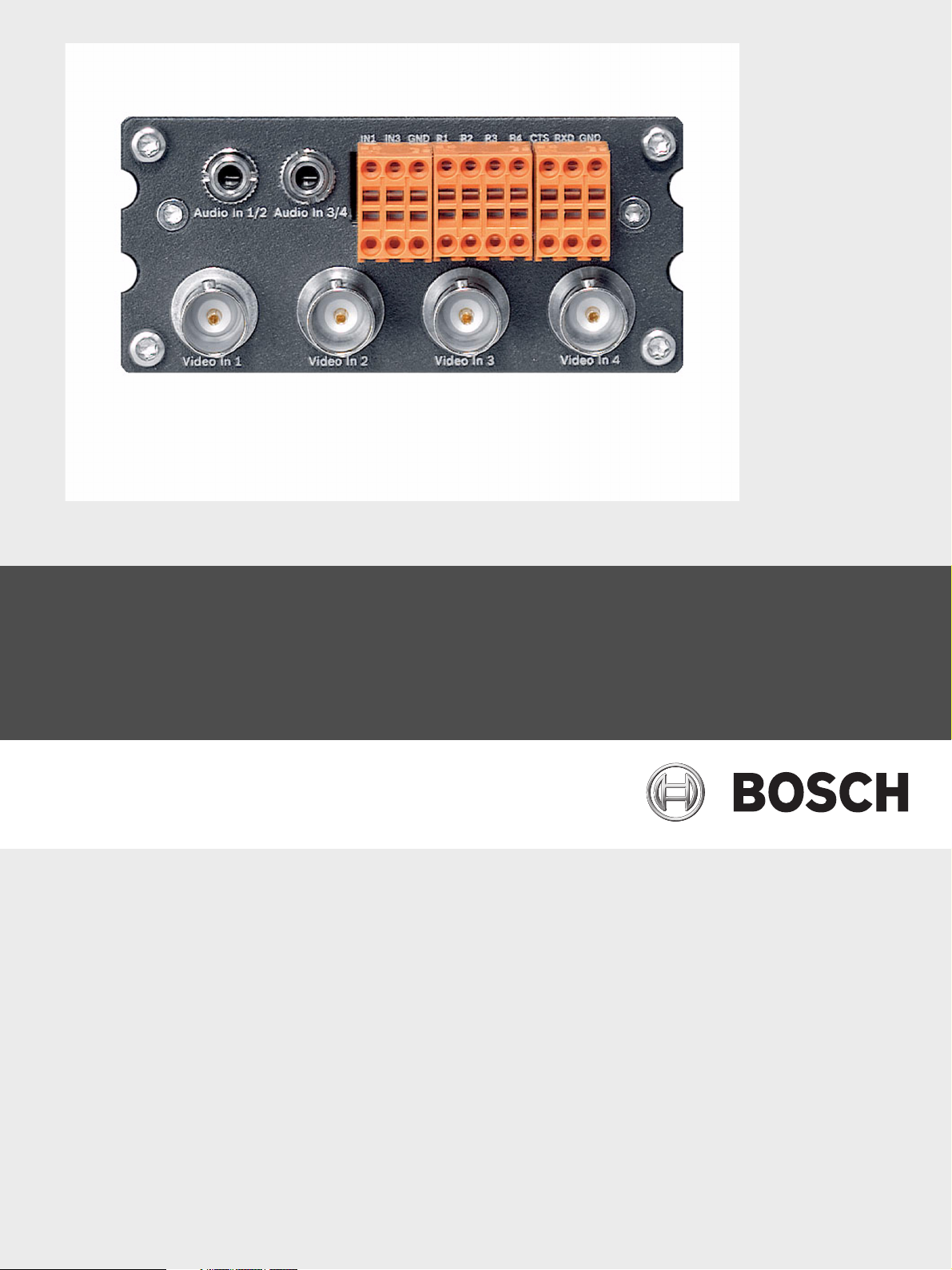
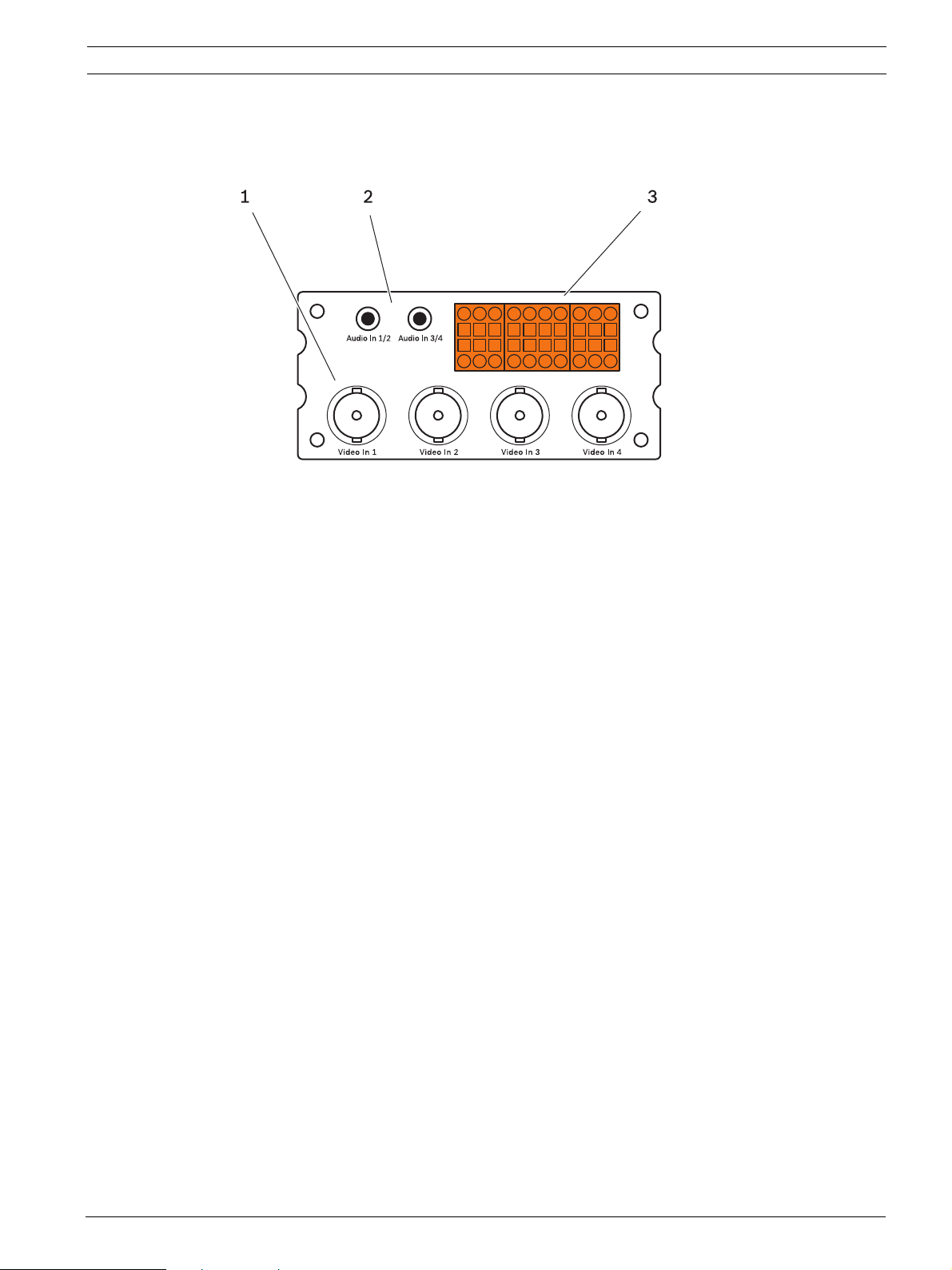
3.4 Connections
1 Video inputs Video In 1 to Video In 4
BNC sockets for attaching video sources
2 Audio inputs (mono) Audio In 1/2 and Audio In 3/4
3.5 mm / 1/8 in. stereo sockets line-outs for connecting audio cables
(only audio versions of the module)
3 Terminal block
for alarm inputs, relay outputs and serial interface
Bosch Security Systems Installation and Operating Manual DOC | V4.0 | 2009.06

16 en | Product Description VIP X1600 M4S
DOC | V4.0 | 2009.06 Installation and Operating Manual Bosch Security Systems
VIP X1600 M4S Installation | en 17
!
!
!
4 Installation
4.1 Preparations
The module is exclusively designed for installation in the VIP X1600 XF base. Installing the
units is a quick and easy operation that does not require any additional tools.
4.2 Installing Modules
Installation of the different VIP X1600 XF modules in the VIP X1600 XF base is described in
the relevant Quick Installation Guide. Please also take note of the following basic notes when
installing a unit.
CAUTION!
Do not install a module in a different housing and do not operate the unit outside of the
VIP X1600 XF base. The ambient temperature during installation must be between
0 and +50 °C (+32 and +122 °F), and the relative humidity must not exceed 80% (noncondensing).
Installation Sequence and Capacity of the VIP X1600 XF Base
CAUTION!
Ensure that Slot 1 is always populated by a module, even when modifying the installation.
Malfunctions may occur when the VIP X1600 XF is switched on without a functional module in
Slot 1.
You can install up to four modules in a VIP X1600 XF base. Slot 1 must always be the first slot
that is populated. The remaining slots can be populated in any order desired. It is also
possible to install and remove modules during operation.
Cooling
CAUTION!
Whenever the installation is modified, or modules are exchanged or supplemented, it is
essential that all unpopulated slots are properly covered on the rear panel of the VIP X1600 XF
base.
The installed modules generate a high volume of heat during operation. As a result, it is
essential that a functional heat dissipation system is in place for problem-free operation of a
VIP X1600 XF.
Bosch Security Systems Installation and Operating Manual DOC | V4.0 | 2009.06
18 en | Installation VIP X1600 M4S
!
Rating Plates
Every module has a label on the circuit board containing a printed MAC address by which the
module can be uniquely identified. Take note of this MAC address and the location in the
VIP X1600 XF base before installation so that you can later identify the module, even after it
has been inserted, for example when performing fault diagnosis.
Removing and Exchanging Modules
It is also possible to install, remove and exchange modules during operation.
CAUTION!
Ensure that Slot 1 is always populated by a module, even when modifying the installation.
Malfunctions may occur when the VIP X1600 XF is switched on without a functional module in
Slot 1.
1. Before removing a module, terminate all recordings currently running in this module.
2. When installing a module, please ensure that the cover is kept for future use.
3. When removing a module, it is essential that the corresponding slot be closed with the
cover if a module is no longer to be used in this slot. The opening must be closed to
ensure that the unit remains cool.
DOC | V4.0 | 2009.06 Installation and Operating Manual Bosch Security Systems

VIP X1600 M4S Installation | en 19
4.3 Connections
Cameras
You can connect a maximum of four video sources to the module. Any cameras and other
video sources that produce a standard PAL or NTSC signal are suitable.
1. Connect the cameras or other video sources to the BNC sockets Video In 1 to Video In 4
using a video cable (75 Ohm, BNC plug).
2. If the video signal is not looped through, termination is performed by a software setting if
necessary (see Section 5.17 Advanced Mode: Video Input, page 42).
Audio Connections
The audio version of the VIP X1600 M4S module has two audio line inputs for a total of four
mono signals.
The audio signals are transmitted at the same time as the video signals. As a result, you can
connect a speaker or door intercom system at the destination point, for example. The
following specification should be complied with in all cases:
Impedance 9 kOhm typ., 5.5 V
The stereo plugs must be connected as follows:
Contact Audio In 1/2 Audio In 3/4
Tip Channel 1 Channel 3
Middle ring Channel 2 Channel 4
Lower ring Ground Ground
max. input voltage.
p-p
Bosch Security Systems Installation and Operating Manual DOC | V4.0 | 2009.06
20 en | Installation VIP X1600 M4S
!
i
i
Data interface
The bidirectional data interface is used to control units connected to the module, such as a
dome camera with a motorized lens. The connection supports the RS-232, RS-422 and RS-485
transmission standards.
The module offers the serial interface via the orange terminal block (see Section 8.8 Terminal
Block, page 107).
The range of controllable equipment is expanding constantly. The manufacturers of the
relevant equipment provide specific information on installation and control.
CAUTION!
Please take note of the appropriate documentation when installing and operating the unit to
be controlled.
The documentation contains important safety instructions and information about permitted
uses.
NOTICE!
A video connection is necessary to transmit transparent data.
Alarm Inputs
The module offers four alarm inputs via the orange terminal block (see Section 8.8 Terminal
Block, page 107). The alarm inputs are used to connect to external alarm devices such as door
contacts or sensors. With the appropriate configuration, an alarm sensor can automatically
connect the VIP X1600 XF to a remote location, for example.
A zero potential closing contact or switch can be used as the actuator.
NOTICE!
If possible, use a bounce-free contact system as the actuator.
X Connect the lines to the appropriate terminals on the orange terminal block (IN1 to IN4)
and check that the connection is secure.
DOC | V4.0 | 2009.06 Installation and Operating Manual Bosch Security Systems
VIP X1600 M4S Installation | en 21
!
i
Relay Outputs
The module has four relay outputs for switching external units such as lamps or alarm sirens.
You can operate these relay outputs manually while there is an active connection to the
module. The outputs can also be configured to automatically activate sirens or other alarm
units in response to an alarm signal. The relay outputs are also located on the orange terminal
block (see Section 8.8 Terminal Block, page 107).
CAUTION!
A maximum load of 30 V and 2 A may be applied to the relay contacts.
X Connect the lines to the appropriate terminals on the orange terminal block (R1 to R4)
and check that the connections are secure.
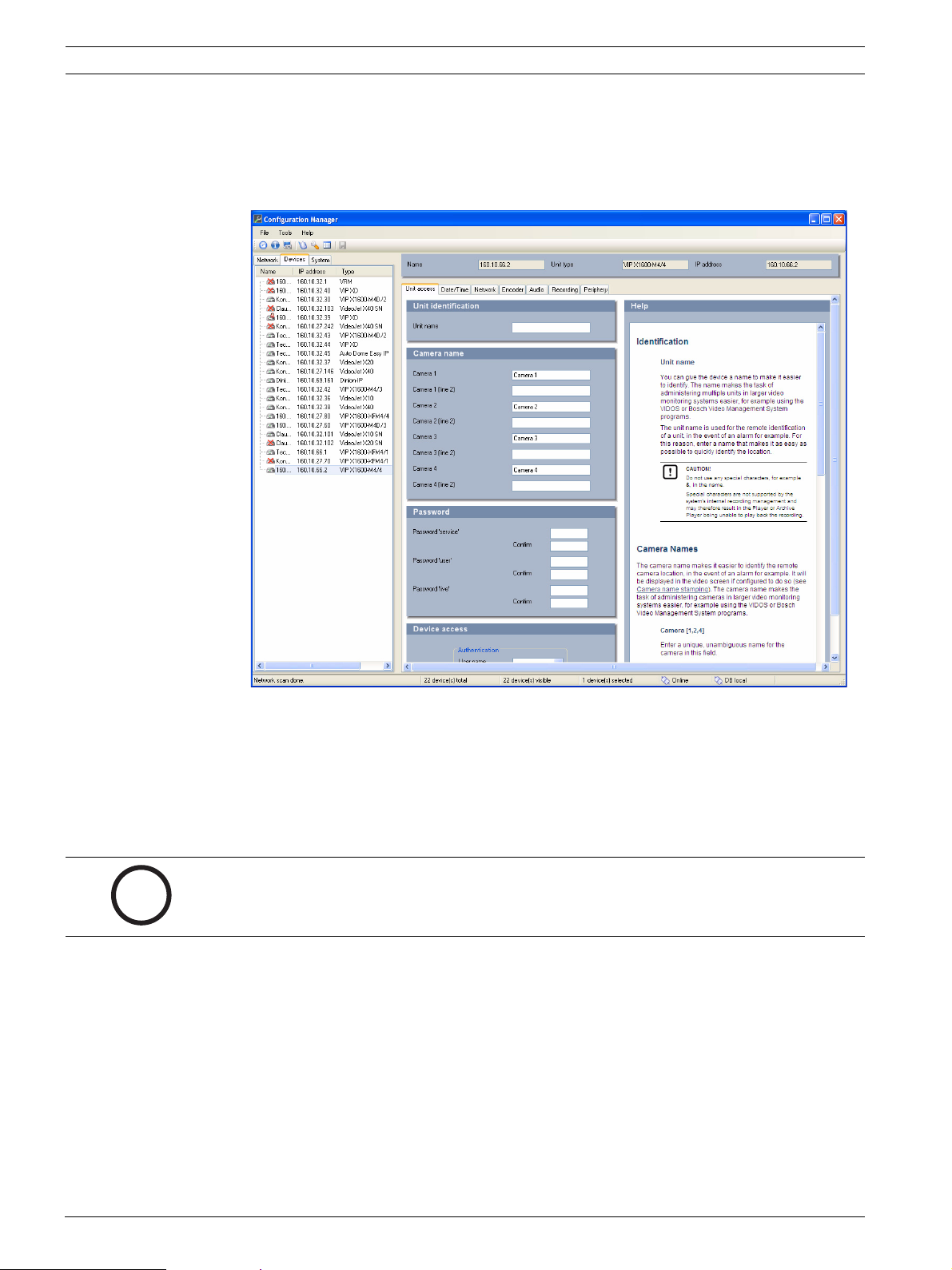
4.4 Setup Using the Configuration Manager
The Configuration Manager program can be found on the product CD contained in the
VIP X1600 XF base's scope of delivery. This program allows you to implement and set up new
modules quickly and conveniently.
NOTICE!
Using the Configuration Manager to set all parameters in the module is an alternative to
configuration by means of a Web browser, as described in chapter 5 of this manual.
Installing the Program
1. Insert the CD into the computer's CD-ROM drive.
2. If the CD does not start automatically, open the Configuration Manager directory using
Windows Explorer and double-click Setup.exe.
3. Follow the on-screen instructions.
Bosch Security Systems Installation and Operating Manual DOC | V4.0 | 2009.06
22 en | Installation VIP X1600 M4S
i
Configuring the Module
You can start the Configuration Manager immediately after installation.
1. Double-click the icon on the desktop or start the program via the Start menu. After the
program has started, the network is immediately searched for compatible video servers.
2. You can start the configuration if the module is shown in the list in the left section of the
window. To do this, right-click the entry for the module.
3. Click Unit network settings... in the popup menu.
4. In the Unit IP address field, enter a valid IP address for your network (for example
192.168.0.17) and click OK. The unit reboots and the IP address is valid.
5. If required, enter an appropriate subnet mask for the IP address, and additional network
data.
NOTICE!
You must reboot to activate the new IP address, a new subnet mask or a gateway IP address.
Reboot
You can trigger the reboot directly with the assistance of the Configuration Manager.
X Right click the entry for the module in the list in the left section of the window and select
the Reset command.
Additional Parameters
You can check and set additional parameters with the assistance of the Configuration
Manager. You can find detailed information on this in the documentation for this program.
DOC | V4.0 | 2009.06 Installation and Operating Manual Bosch Security Systems
VIP X1600 M4S Configuration Using a Web Browser | en 23
i
5 Configuration Using a Web Browser
5.1 Connecting
The integrated HTTP server in the module offers you the option of configuring the unit over
the network with a Web browser. This option is an alternative to configuration using the
Configuration Manager program and is considerably richer in function and more convenient
than configuration using the terminal program.
System requirements
– Computer with Windows XP or Windows Vista operating system
– Network access (Intranet or Internet)
– Microsoft Internet Explorer (version 6.0 or higher)
– Screen resolution 1,024 × 768 pixels
– 16- or 32-bit color depth
– Installed Sun JVM
NOTICE!
Please note the information in the System Requirements document on the product CD
supplied with the VIP X1600 XF base. If necessary, you can install the required programs and
controls from the product CD.
The Web browser must be configured to enable Cookies to be set from the IP address of the
unit.
Under Windows Vista, the protected mode on the Security tab under Internet Options must
be deactivated.
You can find notes on using Microsoft Internet Explorer in the online Help in Internet Explorer.
Installing MPEG ActiveX
Suitable MPEG ActiveX software must be installed on the computer to allow the live video
images to be played back. If necessary, you can install the program from the product CD.
1. Insert the product CD into the computer's CD-ROM drive. If the CD does not start
automatically, open the root directory of the CD in Windows Explorer and double-click
MPEGAx.exe.
2. Follow the on-screen instructions.
Bosch Security Systems Installation and Operating Manual DOC | V4.0 | 2009.06
24 en | Configuration Using a Web Browser VIP X1600 M4S
i
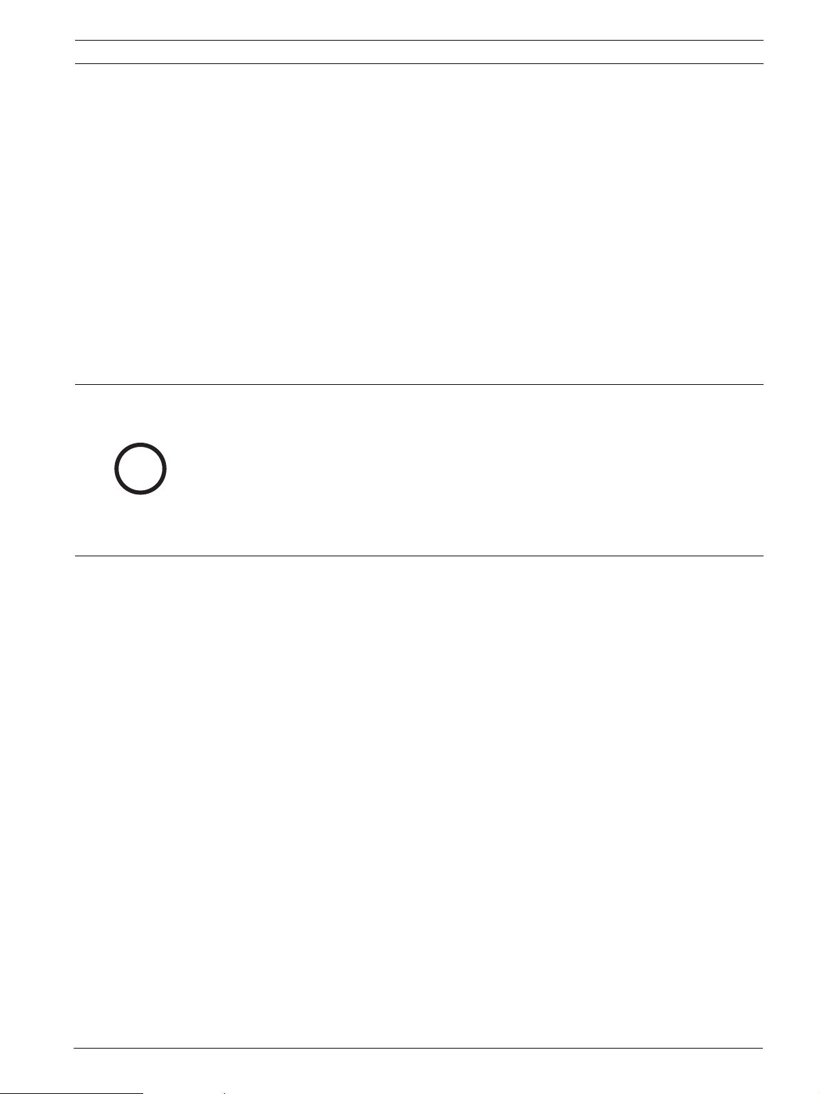
Establishing the Connection
At least the module in Slot 1 must be assigned a valid IP address and a compatible subnet
mask to operate the VIP X1600 XF on your network.
The following default address is preset at the factory: 192.168.0.1
1. Start the Web browser.
2. Enter the module's IP address as the URL. The connection is established and after a short
time you will see the LIVEPAGE with the video image.
Maximum Number of Connections
If you do not connect, the unit may have reached its maximum number of connections.
Depending on the unit and network configuration, each module can have up to 25 Web
browser connections or up to 50 connections via VIDOS or Bosch Video Management System.
Protected Module
If the module is password protected against unauthorized access, the Web browser displays a
message to that effect and prompts you to enter the password when you call up accessprotected areas.
NOTICE!
The module offers the option to limit the extent of access using various authorization levels
(see Section 5.11 Advanced Mode: Password, page 35).
1. Enter the user name and associated password in the corresponding text fields.
2. Click OK. If the password is entered correctly, the Web browser displays the page that
was called up.
Protected Network
If a RADIUS server is employed in the network for managing access rights (802.1x
authentication), the module must be configured accordingly, otherwise no communication is
possible.
DOC | V4.0 | 2009.06 Installation and Operating Manual Bosch Security Systems
VIP X1600 M4S Configuration Using a Web Browser | en 25
!
!
To configure the unit, you must connect the VIP X1600 XF directly to a computer using a
network cable. This is because communication via the network is not enabled until the
Identity and Password parameters have been set and successfully authenticated (see
Section 5.38 Advanced Mode: Advanced, page 77).
CAUTION!
The switch used for the network must support the multi-host operation when using 802.1x
authentication and must be configured so that a VIP X1600 XF with several modules can try
several hosts for communicating over the network.
5.2 Configuration Menu
The SETTINGS page provides access to the configuration menu, which contains all the unit's
parameters arranged in groups. You can view the current settings by opening one of the
configuration screens. You can change the settings by entering new values or by selecting a
predefined value from a list field.
There are two options for configuring the unit or checking the current settings:
– Basic mode
– Advanced mode
In Basic Mode the most important parameters are arranged in seven groups. This allows you
to change the basic settings with just a few entries and then put the device into operation.
Advanced Mode is recommended for expert users or system support personnel. You can
access all unit parameters in this mode. Settings that affect the fundamental functionality of
the unit (such as firmware updates) can only be altered in the advanced mode.
All parameter groups are described in this chapter in the order in which they are listed in the
configuration menu, from the top of the screen to the bottom.
CAUTION!
The settings in the advanced mode should only be processed or modified by expert users or
system support personnel.
All settings are stored in the module's memory so that they are retained even if the power
supply is interrupted.
Bosch Security Systems Installation and Operating Manual DOC | V4.0 | 2009.06

26 en | Configuration Using a Web Browser VIP X1600 M4S
!
Starting Configuration
X Click the SETTINGS link in the upper section of the window. The Web browser opens a
new page with the configuration menu.
Navigation
1. Click one of the menu items in the left window margin. The corresponding submenu is
displayed.
2. Click one of the entries in the submenu. The Web browser opens the corresponding
page.
Making Changes
Each configuration screen shows the current settings. You can change the settings by entering
new values or by selecting a predefined value from a list field.
X After each change, click Set to save the change.
CAUTION!
Save each change with the associated Set button.
Clicking the Set button saves the settings only in the current field. Changes in any other fields
are ignored.
DOC | V4.0 | 2009.06 Installation and Operating Manual Bosch Security Systems
VIP X1600 M4S Configuration Using a Web Browser | en 27
!
!
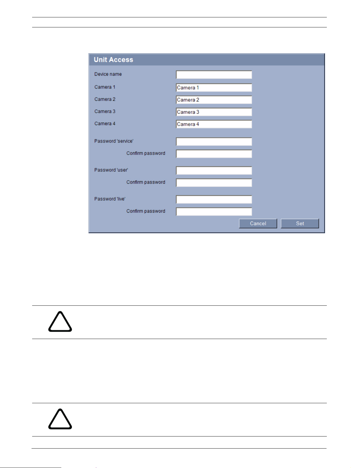
5.3 Basic Mode: Unit Access
Device name
You can give the module a name to make it easier to identify. The name makes the task of
administering multiple units in larger video monitoring systems easier, for example using the
VIDOS or Bosch Video Management System programs.
The device name is used for the remote identification of a module, in the event of an alarm for
example. For this reason, enter a name that makes it as easy as possible to quickly identify the
location.
CAUTION!
Do not use any special characters, for example &, in the name.
Special characters are not supported by the system's internal recording management and may
therefore result in the Player or Archive Player being unable to play back the recording.
Camera 1 to Camera 4
The camera name makes it easier to identify the remote camera location, in the event of an
alarm for example. It will be displayed in the video screen if configured to do so (see
Section Camera name stamping, page 37). The camera name makes the task of administering
cameras in larger video monitoring systems easier, for example using the VIDOS or Bosch
Video Management System programs.
Enter a unique, unambiguous name for the camera in this field.
CAUTION!
Do not use any special characters, for example &, in the name.
Special characters are not supported by the system's internal recording management and may
therefore result in the Player or Archive Player being unable to play back the recording.
Bosch Security Systems Installation and Operating Manual DOC | V4.0 | 2009.06
28 en | Configuration Using a Web Browser VIP X1600 M4S
i
i
i
Password
A module is generally protected by a password to prevent unauthorized access to the unit.
You can use different authorization levels to limit access.
The module operates with three authorization levels: service, user and live.
The highest authorization level is service. After entering the correct password, this user name
allows you to use all the functions of the module and change all configuration settings.
With the user authorization level, you can operate the unit and also control cameras, for
example, but you cannot change the configuration.
The lowest authorization level is live. It can only be used to view the live video image and
switch between the different live image displays.
You can define and change a password for each authorization level if you are logged in as
service or if the unit is not password protected.
Enter the password for the appropriate authorization level here.
NOTICE!
Proper password protection is only guaranteed when all higher authorization levels are also
protected with a password. If a live password is assigned, for example, a service and a user
password must also be set. When assigning passwords, you should therefore always start
from the highest authorization level, service, and use different passwords.
Confirm password
In each case, enter the new password a second time to eliminate typing mistakes.
NOTICE!
A new password is only saved when you click the Set button. You should therefore click the
Set button immediately after entering and confirming a password.
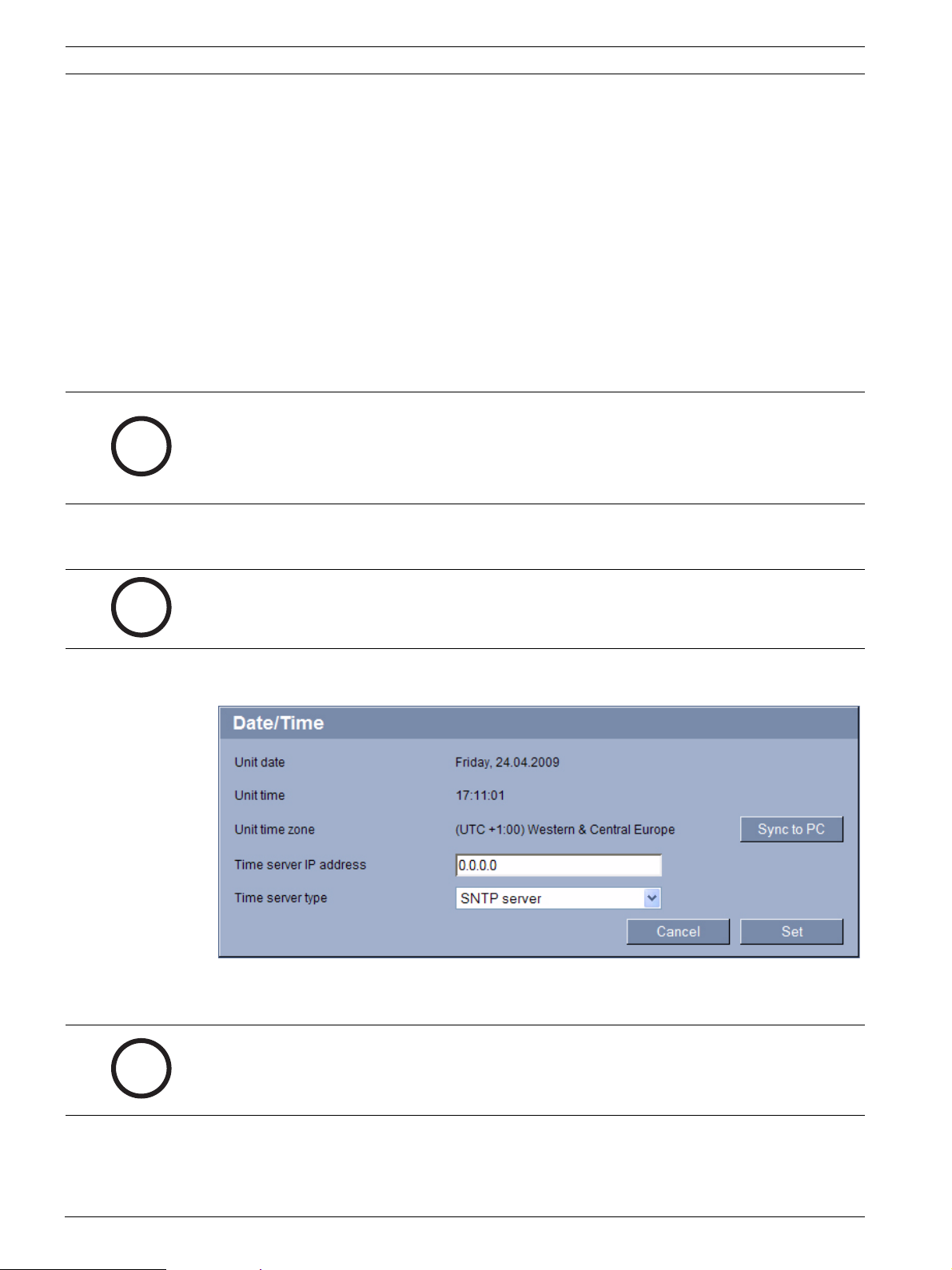
5.4 Basic Mode: Date/Time
Unit date/Unit time/Unit time zone
NOTICE!
The module in Slot 1 of the VIP X1600 XF is the time server for the modules in Slots 2 to 4.
Consequently, the Sync to PC button is only active for the module in Slot 1. The button is
deactivated for modules in Slots 2 to 4.
If there are multiple devices operating in your system or network, it is important to
synchronize their internal clocks. For example, it is only possible to identify and correctly
DOC | V4.0 | 2009.06 Installation and Operating Manual Bosch Security Systems
VIP X1600 M4S Configuration Using a Web Browser | en 29
!
evaluate simultaneous recordings when all units are operating on the same time. If necessary,
you can synchronize the module with your computer's system settings.
X Click the Sync to PC button to copy your computer's system time to the module.
Time server IP address
The module can receive the time signal from a time server using various time server protocols,
and then use it to set the internal clock. The module polls the time signal automatically once
every minute.
X Enter the IP address of a time server here.
Time server type
Select the protocol that is supported by the selected time server. Preferably, you should
select the SNTP server as the protocol. This supports a high level of accuracy and is required
for special applications and subsequent function extensions.
Select Time server for a time server that works with the protocol RFC 868.
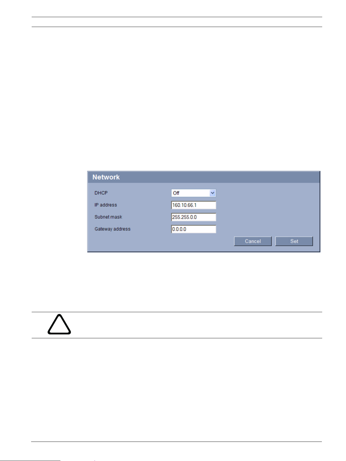
5.5 Basic Mode: Network
The settings in this screen are used to integrate the module into an existing network.
Some changes only take effect after the module is rebooted. In this case, the Set button
changes to Set and Reboot.
1. Make the desired changes.
2. Click the Set and Reboot button. The module is rebooted and the changed settings are
activated.
CAUTION!
If you change the IP address, subnet mask or gateway address, the module is only available
under the new addresses after the reboot.
DHCP
If a DHCP server is employed in the network for the dynamic assignment of IP addresses, you
can activate acceptance of IP addresses automatically assigned to the module.
Certain applications (VIDOS, Bosch Video Management System, Archive Player, Configuration
Manager) use the IP address for the unique assignment of the unit. If you use these
applications, the DHCP server must support the fixed assignment between IP address and
MAC address, and must be appropriately set up so that, once an IP address is assigned, it is
retained each time the system is rebooted.
IP address
Enter the desired IP address for the module. The IP address must be valid for the network.
Bosch Security Systems Installation and Operating Manual DOC | V4.0 | 2009.06
30 en | Configuration Using a Web Browser VIP X1600 M4S
Subnet mask
Enter the appropriate subnet mask for the selected IP address here.
Gateway address
If you want the module to establish a connection to a remote location in a different subnet,
enter the IP address of the gateway here. Otherwise leave the box blank (0.0.0.0).
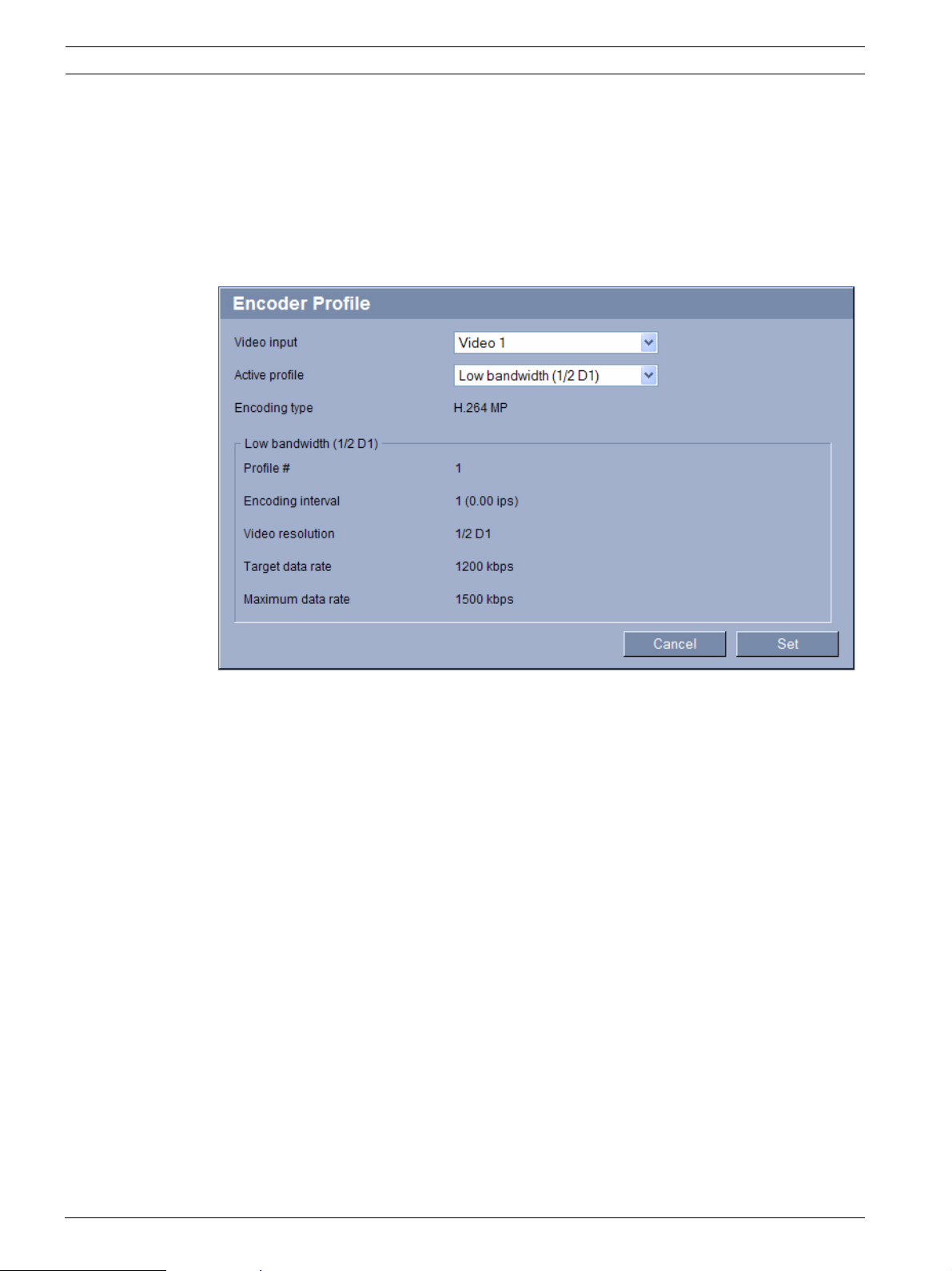
5.6 Basic Mode: Encoder Profile
Video input
Select a video input for the module here; the profile selected in the next field will be applied
to this input. You can select a specific profile for each video input.
Active profile
You can select a profile for encoding the video signal.
You can use this to adapt the video data transmission to the operating environment (for
example network structure, bandwidth, data load).
Pre-programmed profiles are available, each giving priority to different perspectives. When
selecting a profile, details are displayed in the list field.
– Low bandwidth (CIF)
High quality for low bandwidth connections, resolution 352 × 288/240 pixels
– Low delay (2/3 D1)
High quality with low delay, resolution 464 × 576/480 pixels
– High resolution (4CIF/D1)
High resolution for high bandwidth connections, resolution 704 × 576/480 pixels
– DSL
For DSL connections with 500 kbps, resolution 352 × 288/240 pixels
– ISDN (2B)
For ISDN connections via two B-channels, resolution 352 × 288/240 pixels
– ISDN (1B)
For ISDN connections via one B-channel, resolution 352 × 288/240 pixels
DOC | V4.0 | 2009.06 Installation and Operating Manual Bosch Security Systems
 Loading...