

Bosch VJT-X20XF-E, VJT-X40XF-E, VideoJet XF E VJT-X20XF-E, VideoJet XF E VJT-X40XF-E Installation And Operating Manual
VideoJet XF E
VJT-X20XF-E | VJT-X40XF-E
en Installation and Operating Manual


VideoJet XF E Table of Contents | en 3
Bosch Sicherheitssysteme GmbH Installation and Operating Manual DOC | V5.51 | 2012.03
Table of Contents
1Preface 6
1.1 About this manual 6
1.2 Conventions in this manual 6
1.3 Intended use 6
1.4 EU Directives 6
1.5 Rating plate 6
2 Safety information 7
2.1 Electric shock hazard 7
2.2 Installation and operation 7
2.3 Maintenance and repair 8
3 Product description 9
3.1 Parts included 9
3.2 System requirements 9
3.3 Overview of functions 10
3.4 Connections, controls and displays 13
4 Installation 15
4.1 Preparations 15
4.2 Mounting 16
4.3 Installing in a Switch Cabinet 17
4.3.1 Preparations 17
4.3.2 Installing the VideoJet XF E 17
4.4 Connections 19
4.5 Power on/Power off 21
4.6 Setup using Bosch Video Client 21
5 Configuration using a Web browser 23
5.1 Connecting 23
5.2 Configuration menu 25
5.3 Basic Mode: Device Access 27
5.4 Basic Mode: Date/Time 28
5.5 Basic Mode: Network 29
5.6 Basic Mode: Encoder 30
5.7 Basic Mode: Audio 31
5.8 Basic Mode: Recording 31
5.9 Basic Mode: System Overview 32
5.10 Advanced Mode: Identification 32
5.11 Advanced Mode: Password 34
5.12 Advanced Mode: Date/Time 35
5.13 Advanced Mode: Display Stamping 36
5.14 Advanced Mode: Appearance 37
5.15 Advanced Mode: LIVEPAGE Functions 38
5.16 Advanced Mode: Logging 40

4 en | Table of Contents VideoJet XF E
DOC | V5.51 | 2012.03 Installation and Operating Manual Bosch Sicherheitssysteme GmbH
5.17 Advanced Mode: Installer Menu 40
5.18 Advanced Mode: Video Input 41
5.19 Advanced Mode: Privacy Masks 42
5.20 Advanced Mode: Picture Settings 43
5.21 Advanced Mode: Encoder Profile 44
5.22 Advanced Mode: Audio 48
5.23 Advanced Mode: Pixel Counter 49
5.24 Advanced Mode: Storage Management 50
5.25 Advanced Mode: Remote Video Device 52
5.26 Advanced Mode: Recording Profiles 53
5.27 Advanced Mode: Retention Time 56
5.28 Advanced Mode: Recording Scheduler 57
5.29 Advanced Mode: Recording Status 59
5.30 Advanced Mode: Alarm Connections 60
5.31 Advanced Mode: VCA 63
5.32 Advanced Mode: VCA profiles 64
5.33 Advanced Mode: VCA Scheduled 67
5.34 Advanced Mode: VCA Event triggered 69
5.35 Advanced Mode: Audio Alarm 70
5.36 Advanced Mode: Alarm E-Mail 71
5.37 Advanced Mode: Alarm Task Editor 73
5.38 Advanced Mode: Alarm Inputs 74
5.39 Advanced Mode: Relay 74
5.40 Advanced Mode: COM1 76
5.41 Advanced Mode: Network 77
5.42 Advanced Mode: Advanced 81
5.43 Advanced Mode: Multicast 83
5.44 Advanced Mode: FTP Posting 85
5.45 Advanced Mode: IPv4 Filter 86
5.46 Advanced Mode: Encryption 87
5.47 Advanced Mode: Maintenance 87
5.48 Advanced Mode: Licenses 89
5.49 Advanced Mode: System Overview 90
5.50 Function test 90
6Operation 91
6.1 Operation with Microsoft Internet Explorer 91
6.2 The LIVEPAGE 92
6.3 Saving snapshots 96
6.4 Recording video sequences 96
6.5 Running recording program 97
6.6 The RECORDINGS page 98
6.7 Hardware connections between video servers 101
6.8 Operation using software decoders 102
7 Maintenance and upgrades 104
7.1 Testing the network connection 104
7.2 Unit reset 104
7.3 Repairs 104

VideoJet XF E Table of Contents | en 5
Bosch Sicherheitssysteme GmbH Installation and Operating Manual DOC | V5.51 | 2012.03
7.4 Transfer and disposal 105
8 Appendix 106
8.1 Troubleshooting 106
8.2 General malfunctions 106
8.3 Malfunctions with iSCSI connections 108
8.4 LEDs 108
8.5 Processor load 108
8.6 Network connection 109
8.7 Serial interface 109
8.8 Terminal block 109
8.9 Communication with terminal program 110
8.10 Copyrights 111
9 Specifications 113
9.1 VideoJet XF E 113
9.2 Power supply unit delivered 114
Glossary 115
Index 119
6 en | Preface VideoJet XF E
DOC | V5.51 | 2012.03 Installation and Operating Manual Bosch Sicherheitssysteme GmbH
1Preface
1.1 About this manual
This manual is intended for persons responsible for the installation and operation of the
VideoJet XF E and applies to all variants. In the drawings the VideoJet X40XF E is displayed
standing for all versions. International, national and any regional electrical engineering
regulations must be followed at all times. Relevant knowledge of network technology is
required. The manual describes the installation and operation of the unit.
1.2 Conventions in this manual
In this manual, the following symbols and notations are used to draw attention to special
situations:
1.3 Intended use
The VideoJet XF E network video server transfers video, audio and control signals over data
networks (Ethernet LAN, Internet). There are various memory options for recording the
images captured by the connected cameras. The unit is intended for use with CCTV systems.
Various functions can be triggered automatically by incorporating external alarm sensors.
Other applications are not permitted.
In the event of questions concerning the use of the unit which are not answered in this
manual, please contact your sales partner or:
Bosch Sicherheitssysteme GmbH
Robert-Bosch-Ring 5
85630 Grasbrunn
Germany
www.boschsecurity.com
1.4 EU Directives
The VideoJet XF E network video server complies with the requirements of EU Directives 89/
336 (Electromagnetic Compatibility) and 73/23, amended by 93/68 (Low Voltage Directive).
1.5 Rating plate
For exact identification, the model name and serial number are inscribed on the bottom of the
housing. Please make a note of this information before installation, if necessary, so as to have
it to hand in case of questions or when ordering spare parts.
CAUTION!
This symbol indicates that failure to follow the safety instructions described may endanger
persons and cause damage to the unit or other equipment.
It is associated with immediate, direct hazards.
NOTICE!
This symbol refers to features and indicates tips and information for easier, more convenient
use of the unit.

VideoJet XF E Safety information | en 7
Bosch Sicherheitssysteme GmbH Installation and Operating Manual DOC | V5.51 | 2012.03
2 Safety information
2.1 Electric shock hazard
– Never attempt to connect the unit to any power network other than the type for which it
is intended.
– Use only the power supply provided or power supply units with UL approval and a power
output according to LPS or NEC Class 2.
– Never open the housing.
– Never open the housing of the power supply unit.
– If a fault occurs, disconnect the power supply unit from the power supply and from all
other units.
– Install the power supply and the unit only in a dry, weather-protected location.
– When installing in a switch cabinet, ensure that the unit and the power supply units have
sufficient grounding.
– If safe operation of the unit cannot be ensured, remove it from service and secure it to
prevent unauthorized operation. In such cases, have the unit checked by Bosch Security
Systems.
Safe operation is no longer possible in the following cases:
– if there is visible damage to the unit or power cables,
– if the unit no longer operates correctly,
– if the unit has been exposed to rain or moisture,
– if foreign bodies have penetrated the unit,
– after long storage under adverse conditions, or
– after exposure to extreme stress in transit.
2.2 Installation and operation
– The relevant electrical engineering regulations and guidelines must be complied with at
all times during installation.
– Relevant knowledge of network technology is required to install the unit.
– Before installing or operating the unit, make sure you have read and understood the
documentation for the other equipment connected to it, such as cameras. The
documentation contains important safety instructions and information about permitted
uses.
– Perform only the installation and operation steps described in this manual. Any other
actions may lead to personal injury, damage to property or damage to the equipment.
– Please ensure the following installation conditions:
– Do not install the unit close to heaters or other heat sources. Avoid locations
exposed to direct sunlight.
– Allow sufficient space for running cables.
– Ensure that the unit has adequate ventilation. Bear the total heat output in mind,
particularly when installing multiple units in a switch cabinet.
– When making connections, use only the cables supplied or use appropriate cables
immune to electromagnetic interference.
– Position and run all cables so that they are protected from damage, and provide
adequate cable strain relief where needed.
– When installing in a switch cabinet, ensure that the screw joints are free of tension
and subject to as little mechanical stress as possible. Ensure that the unit and the
power supply units have sufficient grounding.

8 en | Safety information VideoJet XF E
DOC | V5.51 | 2012.03 Installation and Operating Manual Bosch Sicherheitssysteme GmbH
2.3 Maintenance and repair
– Never open the housing of the VideoJet XF E. The unit does not contain any user-
serviceable parts.
– Never open the housing of the power supply unit. The power supply unit does not contain
any user-serviceable parts.
– Ensure that all maintenance or repair work is carried out only by qualified personnel
(electrical engineers or network technology specialists).
VideoJet XF E Product description | en 9
Bosch Sicherheitssysteme GmbH Installation and Operating Manual DOC | V5.51 | 2012.03
3 Product description
3.1 Parts included
– VideoJet X20 XF E or VideoJet X40 XF E network video server
– 2 terminal blocks (6-pin, 8-pin)
– 4 self-adhesive elastic bumpers
– 1 wall-mounting panel
–2 screws
– 2 wall plugs
– 1 power supply unit with 3 primary adapters (EU, US, UK)
– 1 Quick Installation Guide
–1 Safety Hints document
3.2 System requirements
General requirements
– Computer with Windows XP or Windows 7 operating system
– Network access (Intranet or Internet)
– Screen resolution at least 1,024 × 768 pixels
– 16- or 32-bit color depth
– Installed Sun JVM
Additional configuration requirements
– Microsoft Internet Explorer (version 7.0 or higher)
or
– Installed Configuration Manager application (version 4.30 or higher)
Additional operational requirements
– Microsoft Internet Explorer (version 7.0 or higher)
or
– Receiver software, for example Bosch Video Client (version 1.3 or higher) or Bosch Video
Management System (version 3.0 or higher)
or
– H.264 compatible hardware decoder from Bosch Security Systems (for example
VIP XD HD) as a receiver and connected video monitor
– For playing back recordings: connection to storage medium
NOTICE!
Check that the delivery is complete and in perfect condition. Arrange for the unit to be
checked by Bosch Security Systems if you find any damage.
NOTICE!
Also note the information in the Releaseletter document for the respective firmware. For the
latest version of the firmware, required programs and controls, and the current version of the
Bosch Video Client (BVC) management software, access your Bosch product catalog on the
Internet.
The Web browser must be configured to enable cookies to be set from the IP address of the
unit.
In Windows 7, deactivate protected mode on the Security tab under Internet Options.
You can find notes on using Microsoft Internet Explorer in the online Help in Internet Explorer.

10 en | Product description VideoJet XF E
DOC | V5.51 | 2012.03 Installation and Operating Manual Bosch Sicherheitssysteme GmbH
3.3 Overview of functions
Network video server
The VideoJet XF E is a compact network video server for two (VideoJet X20 XF E) or four
(VideoJet X40 XF E) connected video sources. It is primarily designed for encoding video,
audio and control data for transfer over an IP network. With its encoding in the H.264 format,
the VideoJet XF E is ideally suited for making existing analog CCTV cameras IP-compatible and
for remote access to digital VCRs and multiplexers.
The use of existing networks means that integration with CCTV systems or local networks can
be achieved quickly and easily.
Two units, for example a VideoJet XF E as a sender and a VIP XD HD as a receiver, can create
a standalone system for data transfer without a PC. Video images from a single sender can be
received simultaneously on multiple receivers. Audio signals can also be transmitted from and
to compatible units.
Triple Streaming
The VideoJet X20/X40 XF E encoders use Dual Streaming to generate two independent
IP video streams per channel. This allows viewing and recording at two different quality levels
to save disk space and bandwidth. As a third stream for easier third-party integration they
provide an independently configured M-JPEG stream. On alarm, they can send an e-mail with
JPEG images attached.
Video encoding
The VideoJet XF E uses the H.264 video compression standard. Thanks to efficient encoding,
the data rate remains low even with high image quality and can also be adapted to local
conditions within wide limits.
Audio encoding
The VideoJet XF E uses the G.711 and L16 audio compression standards. G.711 is the default
setting both for live transmission and recording. When configuring with a Web browser, you
can select L16 for recording. Using video management systems, L16 is also available for live
audio.
Viewing
View the VideoJet X20/X40 XF E encoder video on a PC using a Web browser, in the Bosch
Video Management System, or integrate it into another video management system. By routing
the IP video to a high-performance VIP XD HD video decoder you can present the video with
ultimate clarity. Adaptive bit rate encoding enables viewing from remote sites over bandwidthlimited connections and wireless connections to mobile clients. Latest HTML5 technologies
provide easy access from Android, Windows Phone and iOS based mobile devices.
Region of interest (ROI)
Get every detail even on lower bandwidth or smaller video window by panning, tilting and
zooming a region-of-interest cut-out from the full image. ROI is possible on both live viewing
and playback of recordings.
Advanced remote playback
Bosch’s latest enhancements—adaptive bit rate encoding and transcoding—allow replay of
recordings over bandwidth-limited connections with smooth browsing through the footage
while not missing any detail. Be it a remote guard searching for a specific evidence or alerted
by alarm notification, quick access to the relevant recording is easily achieved, and recorded
images are presented in original quality even over weak links.

VideoJet XF E Product description | en 11
Bosch Sicherheitssysteme GmbH Installation and Operating Manual DOC | V5.51 | 2012.03
Multicast
In suitably configured networks, the multicast function enables simultaneous real-time video
transmission to multiple receivers. The UDP and IGMP V2 protocols must be implemented on
the network for this function.
Access security
The VideoJet X20/X40 XF E encoders offer various security levels for accessing the network,
the unit, and the data channels. As well as password protection with three levels, they
support 802.1x authentication using a RADIUS server for identification. You can secure Web
browser access by HTTPS using a SSL certificate that is stored in the unit. For total data
protection, each communication channel—video, audio, or serial I/O—can be independently
AES encrypted with 128-bit keys, once the Encryption Site License has been applied.
Remote control
For remote control of external units such as pan or tilt heads for cameras or motorized zoom
lenses, control data is transmitted via the VideoJet XF E's bidirectional serial interface. This
interface can also be used to transmit transparent data.
Motion detector
VideoJet X20/X40 XF E comes with built-in MOTION+ video motion detection. This motion
detection algorithm is based on pixel change and includes object size filtering capabilities and
sensitivity settings.
Dual recording
You can record the streams independently on different media. Thus video can be recorded
centrally on iSCSI drives managed by VRM Video Recording Manager and redundantly on the
local media. If necessary, for example in case of a network failure VRM can fill up the gap in
the central recording (ANR, Automatic Network Replenishment).
Backup
A function for storing the video images displayed on the hard drive of your computer is
available on the LIVEPAGE as well as on the RECORDINGS page. Video sequences can be
stored by means of a mouse click.
ONVIF conformance
Firmware 5.50 introduces conformance to ONVIF 1.02 and ONVIF Profile S, providing
interoperability between network video products regardless of manufacturer. In addition,
Firmware 5.50 supports all applicable features of the ONVIF 2.2 specification.
ONVIF conformant devices are able to exchange live video, audio, metadata and control
information and ensure that they are automatically discovered and connected to network
applications such as video management systems.

12 en | Product description VideoJet XF E
DOC | V5.51 | 2012.03 Installation and Operating Manual Bosch Sicherheitssysteme GmbH
Summary
The VideoJet XF E encoders provide the following main functions:
– Video and data transmission over IP data networks
– Dual Streaming function for the encoder for simultaneous encoding with two individually
definable profiles
– Multicast function for simultaneous image transmission to multiple receivers
– Two (VideoJet X20 XF E) or four (VideoJet X40 XF E) analog BNC composite video inputs
(PAL/NTSC)
– Video encoding to international standard H.264
– Integrated Ethernet port (10/100 Base-T)
– CF slot for standard Type I/II CompactFlash memory card for local storage
– Transparent, bidirectional data channel via RS-232/RS-422/RS-485 serial interface
– Configuration and remote control of all internal functions via TCP/IP, also secured via
HTTPS
– Password protection to prevent unauthorized connection or configuration changes
– Extensive, flexible storage options
– Four alarm inputs and one relay output
– Built-in video sensor for motion alarms
– Event-controlled automatic connection
– Convenient maintenance via uploads
– Flexible encryption of control and data channels
– Authentication according to international standard 802.1x
– Bidirectional audio (mono) for line connections
– Audio encoding to international standards AAC, G.711, and L16
VideoJet XF E Product description | en 13
Bosch Sicherheitssysteme GmbH Installation and Operating Manual DOC | V5.51 | 2012.03
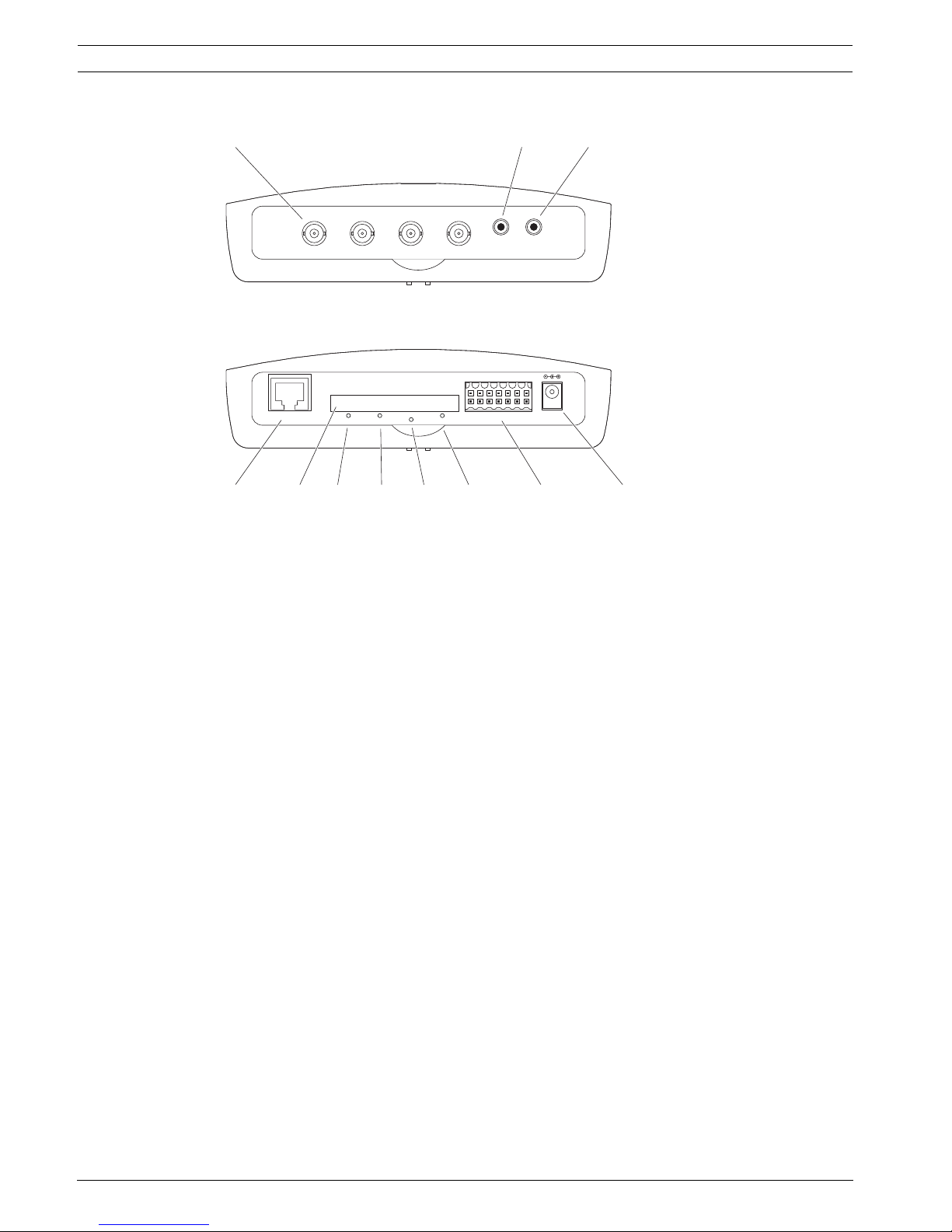
3.4 Connections, controls and displays
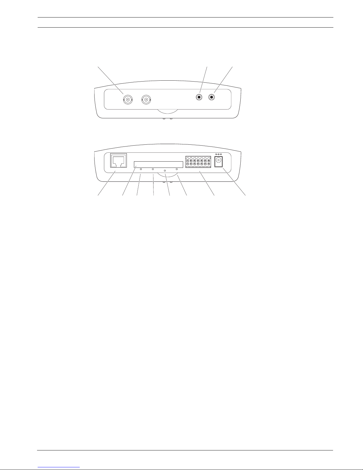
VideoJet X20 XF E
Further topics:
– Section 8.4 LEDs, page 108
– Section 8.8 Terminal block, page 109
1 VIDEO IN 1 and VIDEO IN 2 video inputs
BNC socket for connecting the video source
2 AUDIO IN audio connection (mono)
3.5 mm / 1/8 in stereo socket line-in for connecting two audio sources
3 AUDIO OUT audio connection (mono)
3.5 mm / 1/8 in stereo socket line-out for connecting one audio connection
4 ETH RJ45 socket
for connecting to an Ethernet LAN (local network), 10/100 MBit Base-T
5 CF CARD slot
for one standard Type I/II CompactFlash memory card
6LINK LED
lights up when the unit is connected to the network
7CONNECT LED
lights up when supplied with power and during data transmission
8 Factory reset button
to restore factory default settings
9REC LED
flashes during recordings
10 Terminal block
for alarm inputs, relay output and serial interface
11 12V DC power connector
for connecting the power supply unit
AUDIO IN AUDIO OUT
VIDEO IN 1 VIDEO IN 2
IN1
IN2 12V DC
IN3
IN4
GND
GNDRR
CTS
RTS
RXD
TXD
GND
GND
RECCONNECTLINK
ETH
CF CARD
1
4 5 6 7 8 9 10 11
23
14 en | Product description VideoJet XF E
DOC | V5.51 | 2012.03 Installation and Operating Manual Bosch Sicherheitssysteme GmbH
VideoJet X40 XF E
Further topics:
– Section 8.4 LEDs, page 108
– Section 8.8 Terminal block, page 109
1 VIDEO IN 1 to VIDEO IN 4 video inputs
BNC socket for connecting the video source
2 AUDIO IN audio connection (mono)
3.5 mm / 1/8 in stereo socket line-in for connecting two audio sources
3 AUDIO OUT audio connection (mono)
3.5 mm / 1/8 in stereo socket line-out for connecting one audio connection
4 ETH RJ45 socket
for connecting to an Ethernet LAN (local network), 10/100 MBit Base-T
5 CF CARD slot
for one standard Type I/II CompactFlash memory card
6LINK LED
lights up when the unit is connected to the network
7 CONNECT LED
lights up when supplied with power and during data transmission
8 Factory reset button
to restore factory default settings
9REC LED
lights up during recordings
10 Terminal block
for alarm inputs, relay output and serial interface
11 12V DC power connector
for connecting the power supply unit
AUDIO IN AUDIO OUT
VIDEO IN 1 VIDEO IN 2 VIDEO IN 3 VIDEO IN 4
IN1
IN2 12V DC
IN3
IN4
GND
GNDRR
CTS
RTS
RXD
TXD
GND
GND
RECCONNECTLINK
ETH
CF CARD
1
4 5 6 7 8 9 10 11
23
VideoJet XF E Installation | en 15
Bosch Sicherheitssysteme GmbH Installation and Operating Manual DOC | V5.51 | 2012.03
4 Installation
4.1 Preparations
Please ensure the following installation conditions:
– Do not install the unit close to heaters or other heat sources. Avoid locations exposed to
direct sunlight.
– Allow sufficient space for running cables.
– Ensure that the unit has adequate ventilation. Bear the total heat output in mind,
particularly when installing multiple units in a switch cabinet.
– When making connections, use only the cables supplied or use appropriate cables
immune to electromagnetic interference.
– Position and run all cables so that they are protected from damage, and provide
adequate cable strain relief where needed.
– When installing in a switch cabinet, ensure that the screw joints are free of tension and
subject to as little mechanical stress as possible. Ensure that the unit and the power
supply units have sufficient grounding.
– Avoid impacts, blows and severe vibrations that exceed the specification limits, as these
can irreparably damage the unit.
Further topics:
– Section 9 Specifications, page 113
CAUTION!
The unit is intended for use indoors or in housings.
Select a suitable location for installation that guarantees to meet the environmental
conditions. The ambient temperature for the delivered power supply unit must be between
0 and +40 °C (+32 and +104 °F). The relative humidity must be between 20% and 80%. The
ambient temperature for the VideoJet XF E must be between 0 and +50 °C (+32 and +122 °F).
The relative humidity must not exceed 90%.
The VideoJet XF E generates heat during operation, so you should ensure that there is
adequate ventilation and enough clearance between the unit and heat-sensitive objects or
equipment. During installation, please note the maximum heat value of 31 BTU/h per unit
without the power supply.
16 en | Installation VideoJet XF E
DOC | V5.51 | 2012.03 Installation and Operating Manual Bosch Sicherheitssysteme GmbH
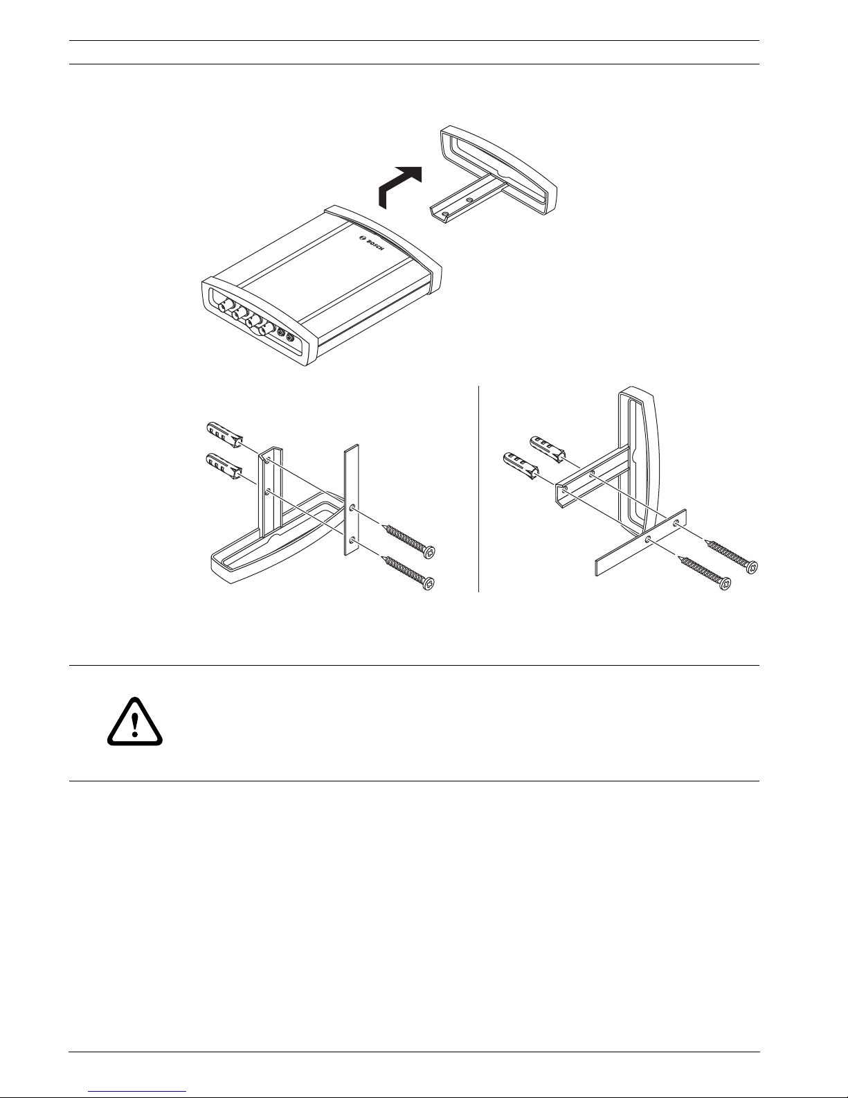
4.2 Mounting
You can secure the VideoJet XF E to walls, below ceilings or any other load-bearing locations
using the wall-mounting panel, in either a vertical or a horizontal position.
– Lift the plastic frame on one side of the housing and carefully remove it from the unit.
– Screw the plastic frame in the required position together with the wall-mounting panel.
– Check that the plastic frame is secure.
– Place the unit on the wall-mounting panel, with the panel positioned between the
housing and the second plastic frame.
– Slide the unit into the plastic frame until you feel it lock securely into place.
– Finally, check that the unit is securely attached in the installation location.
VideoJet X
AUDIO IN AUDIO OUT
VIDEO IN 1
VIDEO IN 2
VIDEO IN 3
VIDEO IN 4
CAUTION!
The mounting location must be able to reliably hold the unit. The load-bearing capacity must
be adequate for four times the weight of the unit.
If mounting the unit in a vertical position, you will need to use the lower plastic frame and
then place the unit onto the frame from above. If mounting the unit in a horizontal position,
you can use either of the two frames.
VideoJet XF E Installation | en 17
Bosch Sicherheitssysteme GmbH Installation and Operating Manual DOC | V5.51 | 2012.03
4.3 Installing in a Switch Cabinet
4.3.1 Preparations
The VideoJet XF E can be installed in a 19-inch rack. A Rack Mount Kit for the installation of up
to 3 VideoJet XF E can be obtained from Bosch. For more information access your Bosch
product catalog on the Internet.
When installing in a switch cabinet, ensure that the screw joints are free of tension and
subject to as little mechanical stress as possible. Ensure that the unit and the power supply
units have sufficient grounding.
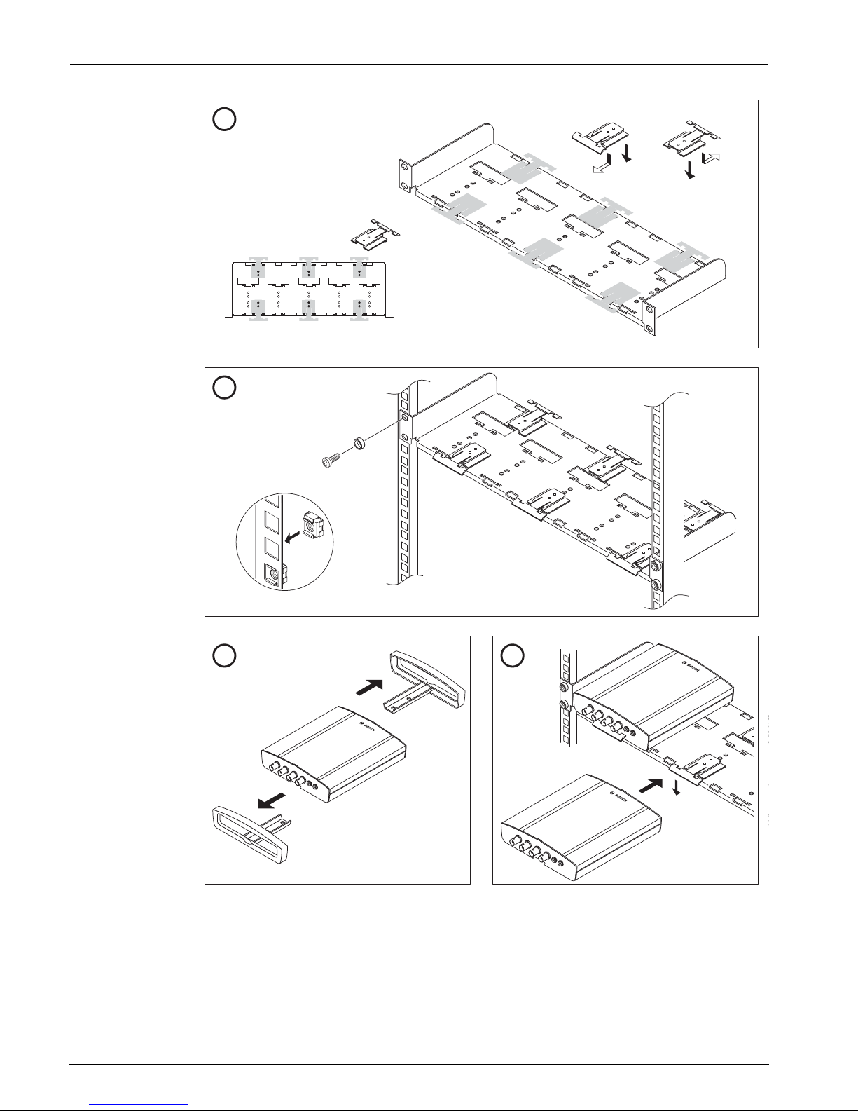
4.3.2 Installing the VideoJet XF E
1. Install the required number of fixing plates, two for each unit.
2. Prepare the switch cabinet in such a manner that you are easily able to insert the rack
mount frame directly at the installation point.
3. Place the cage nuts in the corresponding drillings or spaces in the switch cabinet frame.
4. Lift the empty rack mount frame into the switch cabinet frame and insert the fastening
screws together with the washers.
5. Tighten the screws one after the other and then check once more that all the screws are
tight.
6. Remove the plastic frames from both sides of each VideoJet XF E to be installed.
7. Slide each VideoJet XF E onto the corresponding fixing plates until you feel it lock
securely into place.
CAUTION!
When installing in a switch cabinet, ensure that there is sufficient ventilation for the unit.
The VideoJet XF E generates heat during operation. During installation, please note the
maximum heat value of 31 BTU/h per unit without the power supply.
The ambient temperature for the delivered power supply unit must be between 0 and +40 °C
(+32 and +104 °F). The relative humidity must be between 20% and 80%. The ambient
temperature for the VideoJet XF E must be between 0 and +50 °C (+32 and +122 °F). The
relative humidity must not exceed 90%.
18 en | Installation VideoJet XF E
DOC | V5.51 | 2012.03 Installation and Operating Manual Bosch Sicherheitssysteme GmbH
VideoJet X
AUDIO IN
AUDIO OUT
VIDEO IN 1
VIDEO IN 2
VIDEO IN 3
VIDEO IN 4
VideoJet X
AUDIO IN
AUDIO OUT
VIDEO IN 1
VIDEO IN 2
VIDEO IN 3
VIDEO IN 4
VideoJet X
AUDIO IN
AUDIO OUT
VIDEO IN 1
VIDEO IN 2
VIDEO IN 3
VIDEO IN 4
4×
3× VideoJet XF = 6×
1
3
4
2
VideoJet XF E Installation | en 19
Bosch Sicherheitssysteme GmbH Installation and Operating Manual DOC | V5.51 | 2012.03
4.4 Connections
Camera
You can connect a maximum of two video sources to the VideoJet X20 XF E or a maximum of
four video sources to the VideoJet X40 XF E. Any cameras and other video sources that
produce a standard PAL or NTSC signal are suitable.
1. Connect the cameras or other video sources to the BNC VIDEO IN sockets using a video
cable (75 Ohm, BNC plug).
2. If the video signal is not looped through, termination is performed by a software setting if
necessary.
Further topics:
– Section 5.19 Advanced Mode: Privacy Masks, page 42
Audio connection
The VideoJet XF E has two audio ports for audio line signals (stereo input and mono output).
The audio signals are transmitted two-way and in sync with the video signals. As a result, you
can connect a speaker or door intercom system at the destination point, for example. The
following specifications should be complied with in all cases.
The stereo plugs must be connected as follows:
1. Connect one or two audio sources with line level to the AUDIO IN socket of the
VideoJet XF E with a 3.5 mm stereo plug.
2. Connect a speaker to the AUDIO OUT socket of the VideoJet XF E with a 3.5 mm stereo
plug.
Network
You can connect the VideoJet XF E to a 10/100 Base-T network using a standard UTP
category 5 cable with RJ45 plugs.
Connect the VideoJet XF E to the network via the ETH socket.
CF slot
You can insert a standard Type I/II CompactFlash memory card into the CF CARD slot to
enable recordings to be saved locally. CF cards are the ideal solution for shorter storage times
and temporary recordings, for example alarm recordings or local buffering in the event of
network interruptions.
2 × AUDIO IN: Impedance 9 kOhm typ., 5.5 V
p-p
max. input voltage
1 × AUDIO OUT:3V
p-p
typ. output voltage at 10 kOhm impedance,
2.3 V
p-p
typ. output voltage at 32 Ohm impedance,
1.7 V
p-p
typ. output voltage at 16 Ohm impedance
Contact AUDIO IN function AUDIO OUT function
Tip Line In 1 Line Out 1
Middle ring Line In 2 Line Out 1
Lower ring Ground Ground
NOTICE!
The release letter for the current firmware version includes a list of compatible CF cards.
20 en | Installation VideoJet XF E
DOC | V5.51 | 2012.03 Installation and Operating Manual Bosch Sicherheitssysteme GmbH
Playing back recordings is also possible using a different VideoJet XF E.
1. Carefully slide the CF card into the slot as far as it will go, until it locks into place.
2. To remove the CF card, pull and remove the card.
Data interface
The bidirectional data interface is used to control units connected to the VideoJet XF E, such
as a dome camera with a motorized lens. The connection supports the RS-232, RS-422 and
RS-485 transmission standards. A video connection is necessary to transmit transparent data.
The VideoJet XF E offers the serial interface via the orange terminal block.
The range of controllable equipment is expanding constantly. The manufacturers of the
relevant equipment provide specific information on installation and control.
Further topics:
– Section 8.8 Terminal block, page 109
Alarm inputs
The VideoJet XF E has four alarm inputs on the orange terminal block. The alarm inputs are
used to connect to external alarm devices such as door contacts or sensors. With the
appropriate configuration, an alarm sensor can automatically connect the VideoJet XF E to a
remote location, for example.
A zero potential closing contact or switch can be used as the actuator.
Connect the lines to the appropriate terminals IN1 to IN4 on the orange terminal block
and check that the connections are secure.
Further topics:
– Section 8.8 Terminal block, page 109
Relay output
The VideoJet XF E has one relay output for switching external units such as lamps or alarm
sirens. You can operate the relay output manually while there is an active connection to the
VideoJet XF E. The output can also be configured to automatically activate a siren or another
alarm unit in response to an alarm signal. The relay output is also located on the orange
terminal block.
CAUTION!
If the card is formatted, all existing data is deleted from the card.
You should therefore check whether the CF card contains any data that needs to be backed up
before it is inserted.
CAUTION!
Please take note of the appropriate documentation when installing and operating the unit to
be controlled.
The documentation contains important safety instructions and information about permitted
uses.
NOTICE!
If possible, use a bounce-free contact system as the actuator.
CAUTION!
A maximum load of 30 V
p-p
(SELV) and 200 mA may be applied to the relay contact.
VideoJet XF E Installation | en 21
Bosch Sicherheitssysteme GmbH Installation and Operating Manual DOC | V5.51 | 2012.03
Connect the lines to the appropriate terminals R on the orange terminal block and check
that the connections are secure.
Further topics:
– Section 8.8 Terminal block, page 109
4.5 Power on/Power off
Power supply
The VideoJet XF E does not have a power switch. Power is supplied via a separate unit.
Connect the VideoJet XF E to the power supply unit and plug this into the mains. The unit is
now ready for use. The VideoJet XF E comes supplied with an appropriate power supply unit.
1. Connect the power supply unit to the 12V DC socket on the VideoJet XF E. The jack must
fit a pin of 2 mm (0.079 in) in diameter (polarity: ).
2. Connect the power supply unit to the mains. The VideoJet XF E is ready for use as soon
as the CONNECT LED changes from a red light, indicating the start-up procedure, to a
green light.
Provided the network connection has been correctly made, the green LINK LED also lights up.
The flashing green LED CONNECT signals that data packets are being transmitted via the
network.
4.6 Setup using Bosch Video Client
For the current version of the Bosch Video Client (BVC) management software, access your
Bosch product catalog on the Internet. This program allows you to implement and set up the
encoder in the network quickly and conveniently.
Installing the program
1. Download the Bosch Video Client from the Bosch product catalog on the Internet.
2. Unzip the file.
3. Double-click the installer file.
4. Follow the instructions on the screen to complete the installation.
Configuring the VideoJet XF E
You can start Bosch Video Client immediately after installation.
1. Double-click the icon on the desktop to start the program. Alternatively, start the
application via the Start button and the Programs menu (path: Start/Programs/Bosch
Video Client/Bosch Video Client).
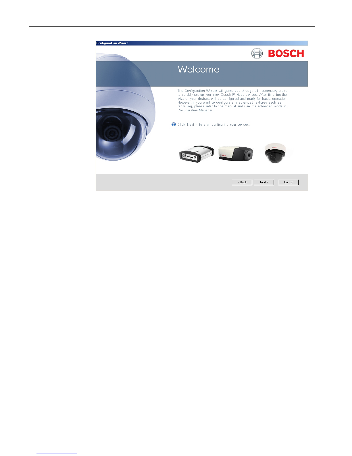
2. When the program is started for the first time, a wizard opens to help you detect and
configure devices on the network.
3. If the wizard does not start automatically, click to open the Configuration Manager
application. Then, click Configuration Wizard... on the Tools menu.
CAUTION!
Use only the power supply unit provided or another power suppply unit with UL approval and
a power output according to LPS or NEC Class 2.
Where necessary, use suitable equipment to ensure that the power supply is free from
interference such as voltage surges, spikes or voltage drops.
Do not connect the VideoJet XF E to the power supply until all other connections have been
made.
22 en | Installation VideoJet XF E
DOC | V5.51 | 2012.03 Installation and Operating Manual Bosch Sicherheitssysteme GmbH
4. Follow the instructions given in the Configuration Wizard window.
Additional parameters
You can check and set additional parameters with the assistance of the Configuration
Manager application in Bosch Video Client. You can find detailed information on this in the
documentation for these applications.
VideoJet XF E Configuration using a Web browser | en 23
Bosch Sicherheitssysteme GmbH Installation and Operating Manual DOC | V5.51 | 2012.03
5 Configuration using a Web browser
5.1 Connecting
The integrated HTTP server in the VideoJet XF E provides you with the option to configure the
unit over the network with a Web browser. This option is an alternative to configuration using
the Configuration Manager application and is considerably richer in function and more
convenient than configuration using the terminal program.
System requirements
– Computer with Windows XP or Windows 7 operating system
– Network access (Intranet or Internet)
– Microsoft Internet Explorer (version 7.0 or higher)
– Screen resolution at least 1,024 × 768 pixels
– 16- or 32-bit color depth
– Installed Sun JVM
Establishing the connection
Before you can operate the VideoJet XF E within your network, it must have a valid IP address
for your network and a compatible subnet mask.
The following default address is preset at the factory: 192.168.0.1
1. Start the Web browser.
2. Enter the IP address of the VideoJet XF E as the URL.
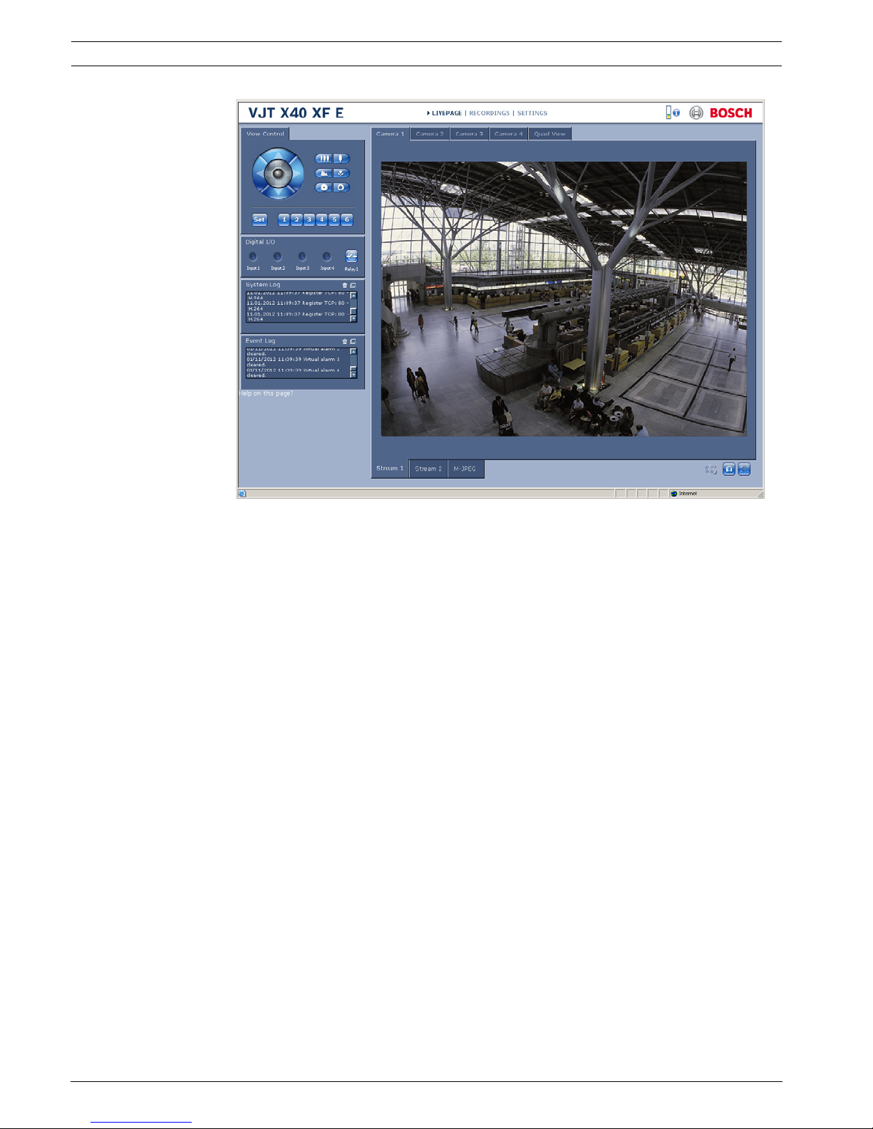
3. During initial installation, confirm the security questions that appear. The connection is
established and after a short time you will see the LIVEPAGE with the video image.
NOTICE!
Also note the information in the Releaseletter document for the respective firmware. For the
latest version of the firmware, required programs and controls, access your Bosch product
catalog on the Internet.
The Web browser must be configured to enable cookies to be set from the IP address of the
unit.
In Windows 7, deactivate protected mode on the Security tab under Internet Options.
You can find notes on using Microsoft Internet Explorer in the online Help in Internet Explorer.
NOTICE!
As a default DHCP is enabled in the VideoJet XF E settings.
With an active DHCP server in the network you must know the IP address assigned by the
DHCP server to operate the VideoJet XF E.
24 en | Configuration using a Web browser VideoJet XF E
DOC | V5.51 | 2012.03 Installation and Operating Manual Bosch Sicherheitssysteme GmbH
Maximum number of connections
If you do not connect, the unit may have reached its maximum number of connections.
Depending on the unit and network configuration, each VideoJet XF E can have up to 25 Web
browser connections or up to 50 connections via Bosch Video Client or Bosch Video
Management System.
Protected VideoJet XF E
The VideoJet XF E offers the option to limit the extent of access using various authorization
levels. If the VideoJet XF E is password protected against unauthorized access, the Web
browser displays a corresponding message and prompts you to enter the password when you
attempt to access protected areas.
1. Enter the user name and associated password in the corresponding text fields.
2. Click OK. If the password is entered correctly, the Web browser displays the page that
was called up.
Further topics:
– Section 5.11 Advanced Mode: Password, page 34
Protected network
If a RADIUS server is employed in the network for managing access rights (802.1x
authentication), the VideoJet XF E must be configured accordingly, otherwise no
communication is possible.
To configure the unit, you must connect the VideoJet XF E directly to a computer using a
network cable. This is because communication via the network is not enabled until the
Identity and Password parameters have been set and successfully authenticated.
Further topics:
– Section Authentication, page 82
VideoJet XF E Configuration using a Web browser | en 25
Bosch Sicherheitssysteme GmbH Installation and Operating Manual DOC | V5.51 | 2012.03
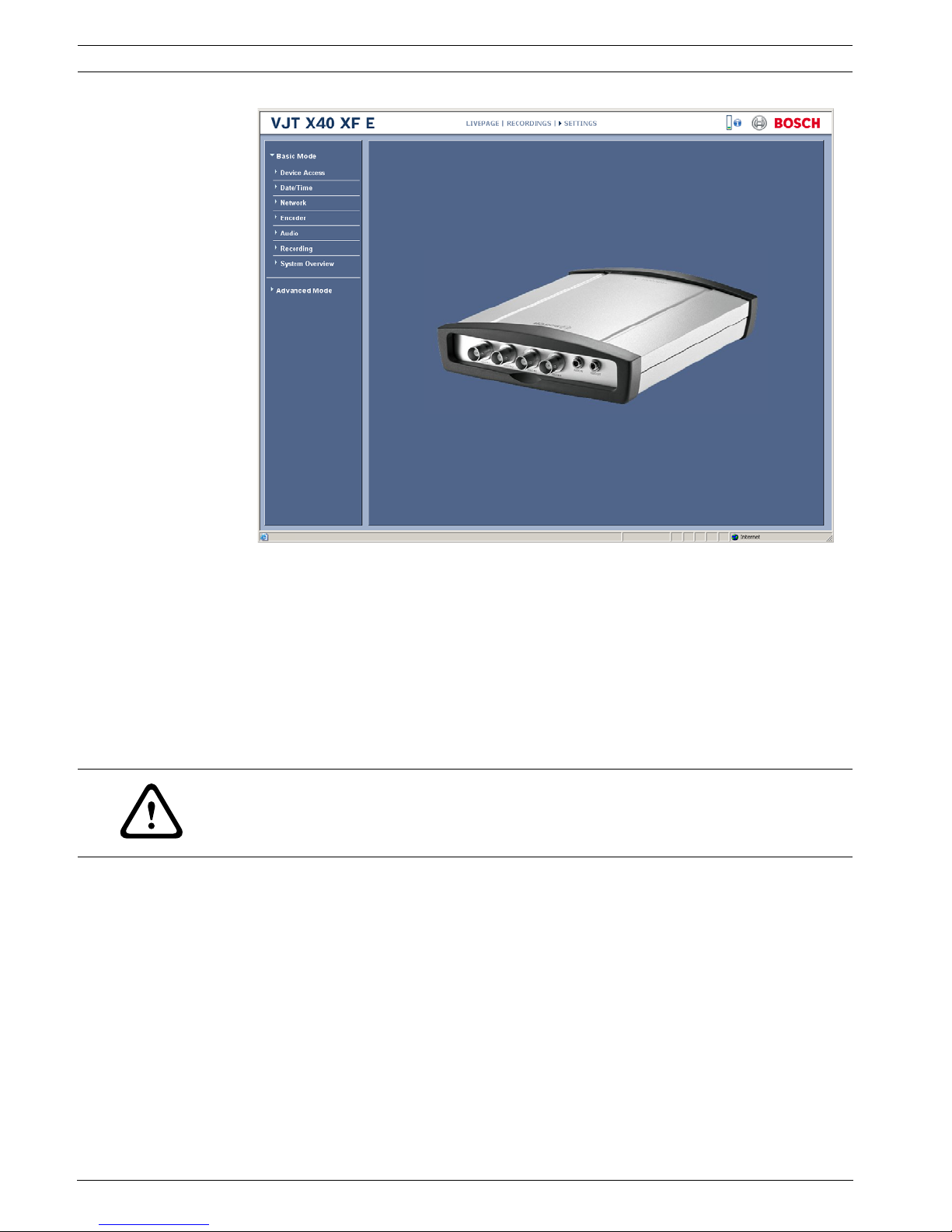
5.2 Configuration menu
The SETTINGS page provides access to the configuration menu, which contains all the unit's
parameters arranged in groups. You can view the current settings by opening one of the
configuration screens. You can change the settings by entering new values or by selecting a
predefined value from a list field.
There are two options for configuring the unit or checking the current settings:
– Basic Mode
– Advanced Mode
In Basic Mode the most important parameters are arranged in seven groups. This allows you
to change the basic settings with just a few entries and then put the device into operation.
Advanced Mode is recommended for expert users or system support personnel. You can
access all device parameters in this mode. Settings that affect the fundamental functionality
of the device (such as firmware updates) can only be altered in Advanced Mode.
All parameter groups are described in this chapter in the order in which they are listed in the
configuration menu, from the top of the screen to the bottom.
All settings are backed up in the VideoJet XF E memory so they are not lost even if the power
fails. The exception is the time settings, which are lost after 72 hours without power if no
central time server is selected.
Further topics:
– Section 5.4 Basic Mode: Date/Time, page 28
– Section 5.12 Advanced Mode: Date/Time, page 35
Starting configuration
Click the SETTINGS link in the upper section of the window. The Web browser opens a
new page with the configuration menu.
CAUTION!
The settings in the Advanced Mode should only be processed or modified by expert users or
system support personnel.
26 en | Configuration using a Web browser VideoJet XF E
DOC | V5.51 | 2012.03 Installation and Operating Manual Bosch Sicherheitssysteme GmbH
Navigation
1. Click one of the menu items in the left window margin. The corresponding submenu is
displayed.
2. Click one of the entries in the submenu. The Web browser opens the corresponding
page.
Making changes
Each configuration screen shows the current settings. You can change the settings by entering
new values or by selecting a predefined value from a list field.
After each change, click Set to save the change.
CAUTION!
Save each change with the associated Set button.
Clicking the Set button saves the settings only in the current field. Changes in any other fields
are ignored.
VideoJet XF E Configuration using a Web browser | en 27
Bosch Sicherheitssysteme GmbH Installation and Operating Manual DOC | V5.51 | 2012.03
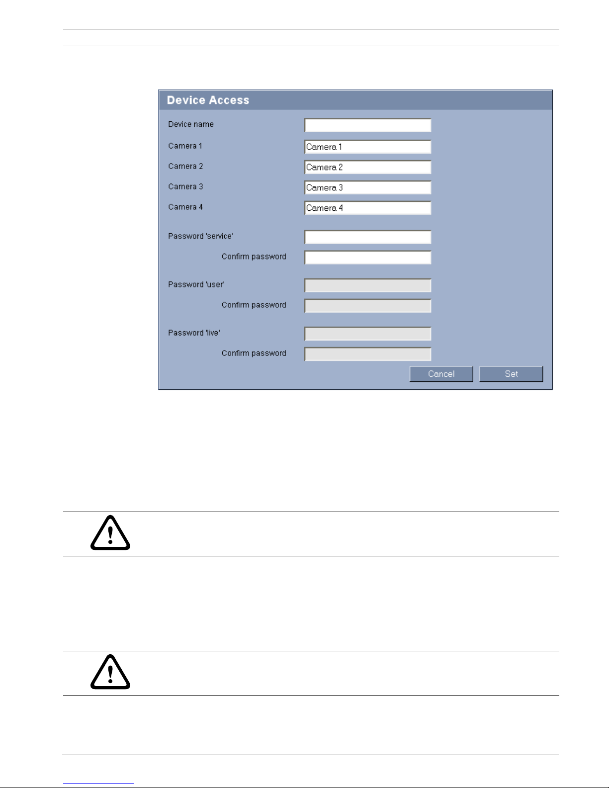
5.3 Basic Mode: Device Access
Device name
You can give the VideoJet XF E a name to make it easier to identify. The name makes the task
of administering multiple units in larger video monitoring systems easier, for example using
the Bosch Video Client or Bosch Video Management System programs.
The device name is used for the remote identification of a unit, in the event of an alarm for
example. For this reason, enter a name that makes it as easy as possible to quickly identify the
location.
Camera 1 to Camera 4
The camera name makes it easier to identify the remote camera location, in the event of an
alarm for example. It will be displayed in the video screen if configured to do so. The camera
name makes the task of administering cameras in larger video monitoring systems easier, for
example using the Bosch Video Client or Bosch Video Management System programs.
Enter unique, unambiguous names for each camera in these fields.
Further topics:
– Section Camera name stamping, page 36
CAUTION!
Do not use any special characters, for example &, in the name.
Special characters are not supported by the system's internal management.
CAUTION!
Do not use any special characters, for example &, in the name.
Special characters are not supported by the system's internal management.
28 en | Configuration using a Web browser VideoJet XF E
DOC | V5.51 | 2012.03 Installation and Operating Manual Bosch Sicherheitssysteme GmbH
Password
A VideoJet XF E is generally protected by a password to prevent unauthorized access to the
unit. You can use different authorization levels to limit access.
The VideoJet XF E operates with three authorization levels: service, user and live.
The highest authorization level is service. After entering the correct password, you can access
all the functions of the VideoJet XF E and change all configuration settings.
With the user authorization level, you can operate the unit, play back recordings and also
control cameras, for example, but you cannot change the configuration.
The lowest authorization level is live. It can only be used to view the live video image and
switch between the different live image displays.
Proper password protection is only guaranteed when all higher authorization levels are also
protected with a password. Therefore, you always have to start from the highest authorization
level when assigning passwords.
You can define and change a password for each authorization level if you are logged in as
service or if the unit is not password protected.
Enter the password for the appropriate authorization level here. The maximum password text
length is 19 characters.
Confirm password
In each case, enter the new password a second time to eliminate typing mistakes.
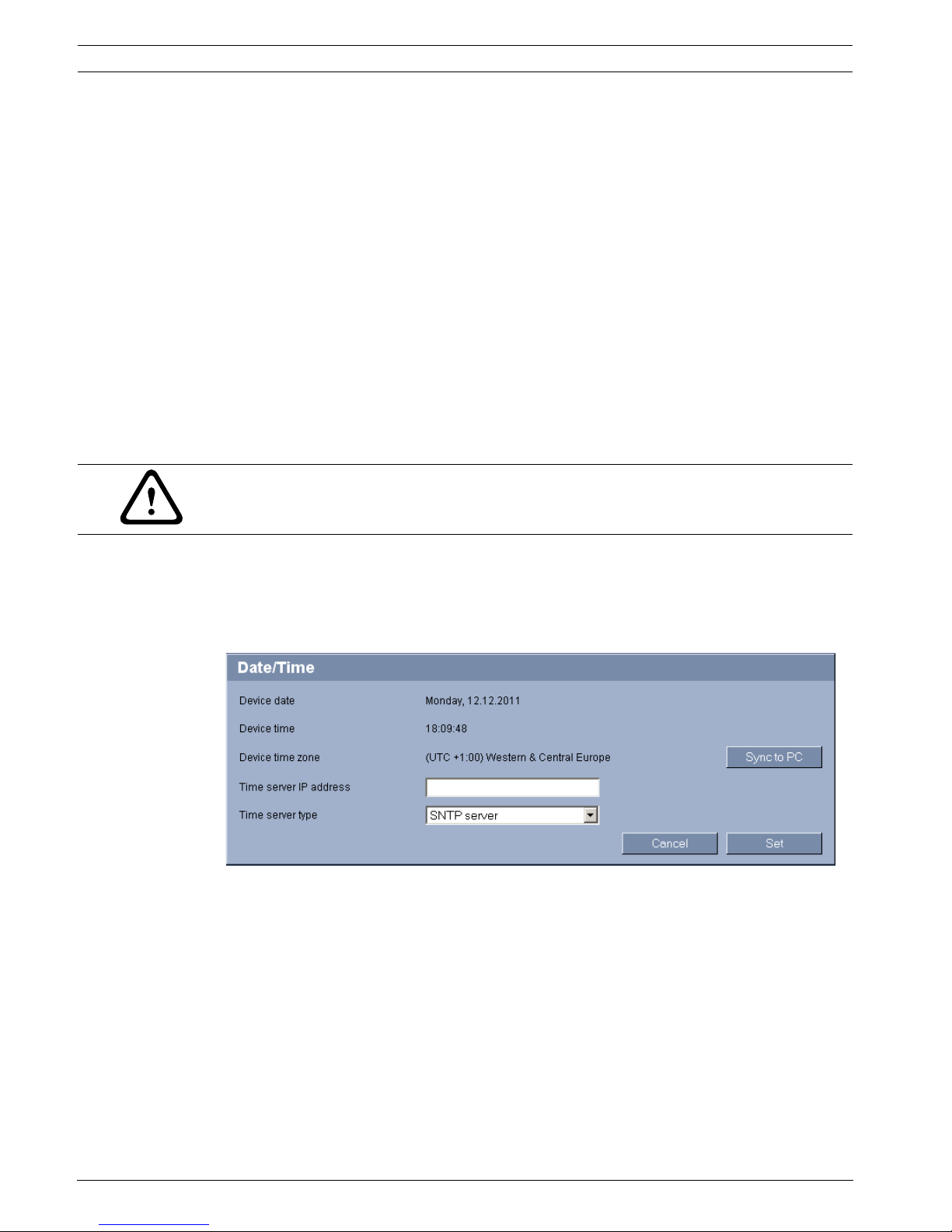
5.4 Basic Mode: Date/Time
Device date / Device time / Device time zone
If there are multiple devices operating in your system or network, it is important to
synchronize their internal clocks. For example, it is only possible to identify and correctly
evaluate simultaneous recordings when all units are operating on the same time. If necessary,
you can synchronize the unit with your computer's system settings.
Click the Sync to PC button to copy your computer's system time to the VideoJet XF E.
Time server IP address
The VideoJet XF E can receive the time signal from a time server using various time server
protocols, and then use it to set the internal clock. The unit polls the time signal automatically
once every minute.
Enter the IP address of a time server here.
CAUTION!
Do not use any special characters, for example &, in the password.
Special characters are not supported by the system's internal management.
VideoJet XF E Configuration using a Web browser | en 29
Bosch Sicherheitssysteme GmbH Installation and Operating Manual DOC | V5.51 | 2012.03
Time server type
Select the protocol that is supported by the selected time server. Preferably, you should
select SNTP server as the protocol. This supports a high level of accuracy and is required for
special applications and subsequent function extensions.
Select Time server for a time server that works with the protocol RFC 868.
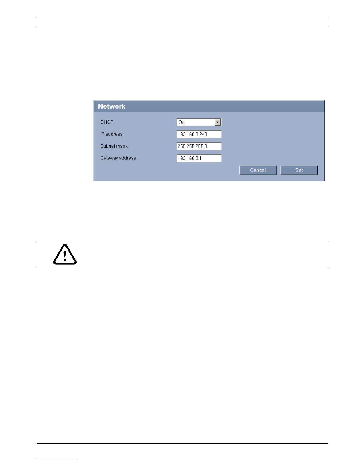
5.5 Basic Mode: Network
The settings on this page are used to integrate the VideoJet XF E into an existing network.
Some changes only take effect after the unit is rebooted. In this case, the Set button changes
to Set and Reboot.
1. Make the desired changes.
2. Click the Set and Reboot button. The VideoJet XF E is rebooted and the changed
settings are activated.
DHCP
If a DHCP server is employed in the network for the dynamic assignment of IP addresses, you
can activate acceptance of IP addresses automatically assigned to the VideoJet XF E.
Certain applications (Bosch Video Client, Bosch Video Management System) use the IP
address for the unique assignment of the unit. If you use these applications, the DHCP server
must support the fixed assignment between IP address and MAC address, and must be
appropriately set up so that, once an IP address is assigned, it is retained each time the
system is rebooted.
IP address
Enter the desired IP address for the VideoJet XF E in this field. The IP address must be valid
for the network.
Subnet mask
Enter the appropriate subnet mask for the selected IP address here.
Gateway address
If you want the unit to establish a connection to a remote location in a different subnet, enter
the IP address of the gateway here. Otherwise leave the box blank (0.0.0.0).
CAUTION!
If you change the IP address, subnet mask, gateway address or the DHCP setting, the
VideoJet XF E is only available under the new addresses after the reboot.
30 en | Configuration using a Web browser VideoJet XF E
DOC | V5.51 | 2012.03 Installation and Operating Manual Bosch Sicherheitssysteme GmbH
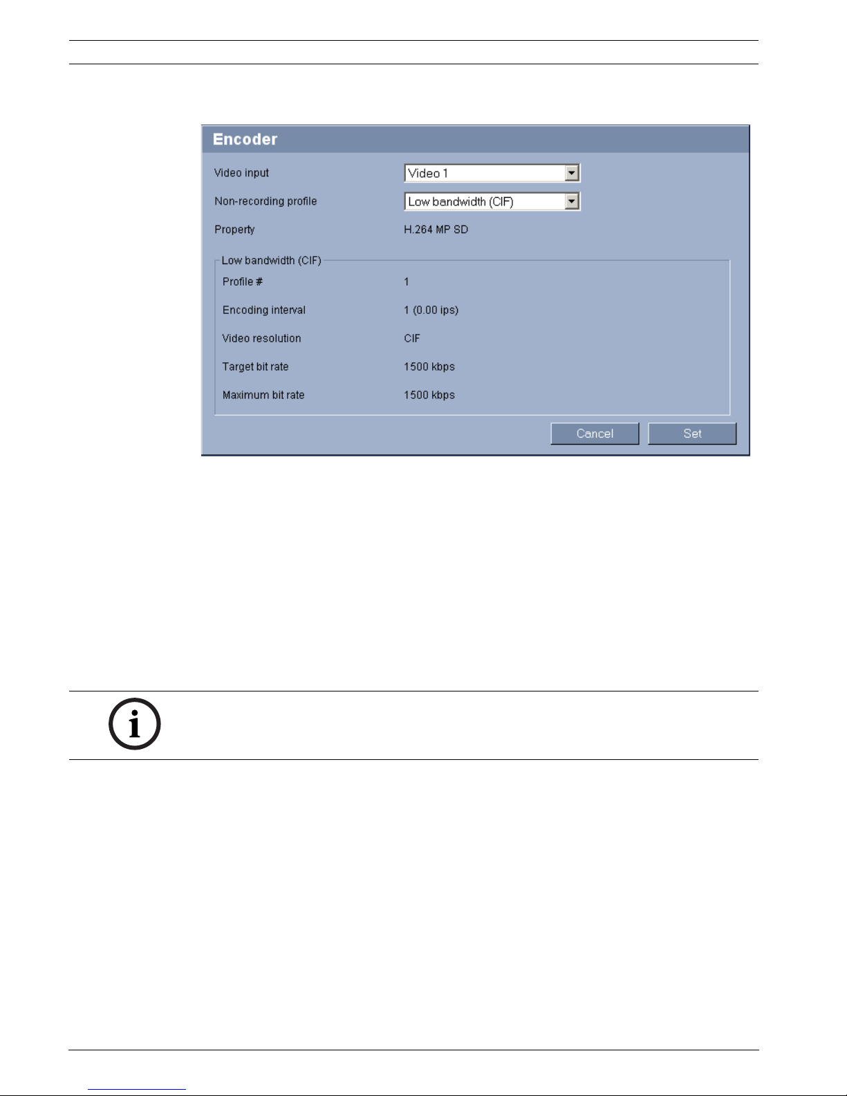
5.6 Basic Mode: Encoder
Video input
Select a video input of the VideoJet XF E here; the profile selected in the next field will be
applied to this input. You can select a specific profile for each video input.
Non-recording profile
You can select a profile for encoding the video signal.
You can use this to adapt the video data transmission to the operating environment (for
example network structure, bandwidth, data load).
Pre-programmed profiles are available, each giving priority to different perspectives. When
selecting a profile, details are displayed in the list field. Below is a brief description of the
factory default settings for the encoder profiles.
– High resolution 1
High quality for connections with the highest bandwidth, resolution 704 × 576/480 pixels
– High resolution 2
High quality for high bandwidth connections, resolution 704 × 576/480 pixels
– Low bandwidth
High resolution for low bandwidth connections, resolution 704 × 576/480 pixels
– DSL
For DSL connections with 500 kbps, resolution 704 × 576/480 pixels
– ISDN (2B)
For ISDN connections via two B-channels, resolution 352 × 288/240 pixels
– ISDN (1B)
For ISDN connections via one B-channel, resolution 352 × 288/240 pixels
NOTICE!
The names and the technical details for the encoder profiles depend on the configuration of
the device.
 Loading...