

Page 1
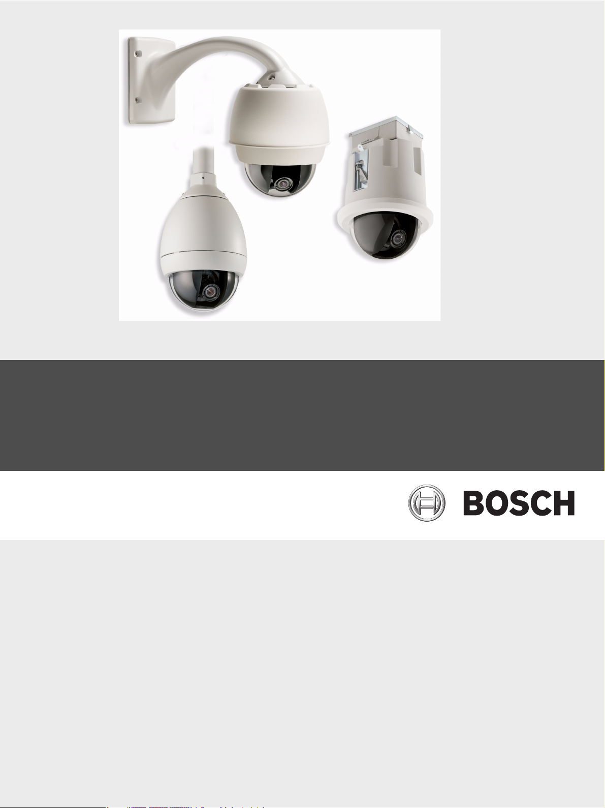
AutoDome 800 Series HD PTZ Camera
VG5 800 Series
en Installation Manual
Page 2

Page 3

AutoDome 800 Series HD PTZ Camera Table of Contents | en 3
Table of Contents
1Safety 7
1.1 Important Safety Instructions 7
1.2 Safety Precautions 9
1.3 Important Notices 9
1.4 Customer Support and Service 13
2 Installing the Pendant Arm Wall, Corner, and Mast (Pole) Mounts 14
2.1 Unpacking 14
2.1.1 Parts List 14
2.1.2 Description 15
2.1.3 Tools Required 15
2.2 Pre-installation Checklist 15
2.3 Mount Power Supply Box 16
2.4 Route Wires and Attach Connectors 17
2.4.1 Power Supply Box Connections 19
2.5 Route Power through Intermediate Power Supply Box 20
2.6 Attach Pendant Arm to Power Supply Box 22
2.7 Make Connections in Power Supply Box 23
2.8 Installing the VG4-A-ARMPLATE 26
2.8.1 Attach the Pendant Arm to the Mounting Plate 27
2.8.2 Route and Connect Wires to a Power Supply Box 27
2.9 Attach Pendant to Arm and Tighten 31
3 Installing Roof Parapet and Pipe Mounts 33
3.1 Unpacking 33
3.1.1 Parts List 33
3.1.2 Description 33
3.1.3 Tools Required 33
3.2 Pre-installation Check List 34
3.3 Mount Power Supply Box 34
3.3.1 Attach Cover Door 36
3.4 Route Wires and Attach Connectors 37
3.4.1 Wiring the Power Supply Box 39
3.4.2 Wiring the Fiber Optic Model 39
3.4.3 Power Supply Box Connections 41
3.5 Installing the VG4-A-9230 Roof Parapet Mount 42
3.6 Installing the VG4-A-9543 Pipe Mount 45
3.7 Wire the Pipe Interface Board 46
3.7.1 Connecting Wires to the Pipe Interface Board 47
3.8 Attach Pendant to Pipe and Tighten 49
4 Cable and Wire Standards 51
4.1 Power 51
4.2 Wire Distance Guide for Pendant 51
4.3 Video and Control Cables 51
4.4 Audio Cables 52
Bosch Security Systems, Inc. Installation Manual F.01U.273.797 | 5.0 | 2012.08
Page 4

4 en | Table of Contents AutoDome 800 Series HD PTZ Camera
5 Alarms and Relay Connections 54
5.1 Alarm Inputs 54
5.2 Connecting Alarms (inputs 1 or 2) 54
5.2.1 Connecting a Normally Open Alarm 54
5.2.2 Connecting a Normally Closed Alarm 54
5.3 Configuring an Open Collector Output 55
6 Using the AutoDome 800 Series 56
6.1 Overview of Features 56
6.2 System Requirements 56
6.3 Connecting the AutoDome 800 Series to the PC 57
6.4 Configuring the AutoDome 800 Series Camera 58
6.4.1 Changing the Network Settings 59
6.5 Configuring Intelligent Tracking 60
6.5.1 Intelligent Tracking Operation 60
6.5.2 Guidelines for Implementing Intelligent Tracking 61
6.6 The Livepage 61
6.6.1 Entering a Keyboard Control Command 64
6.6.2 Using Intelligent Tracking 65
6.6.3 Using Special Functions 65
6.7 Saving Snapshots 66
6.8 Recording Video Sequences 66
6.9 Processor Load 66
6.10 Recordings page 68
6.10.1 Controlling playback 68
7 Configuring the AutoDome 800 Series 70
7.1 Basic Mode: Device Access 70
7.2 Basic Mode: Date/Time 71
7.3 Basic Mode: Network 72
7.4 Basic Mode: Encoder 72
7.5 Basic Mode: Audio 73
7.6 Basic Mode: Recording 73
7.7 Basic Mode: System Overview 74
7.8 Advanced Mode: General 74
7.9 Identification 74
7.10 Password 74
7.11 Date/Time 75
7.12 Display Stamping 76
7.13 Advanced Mode: Web Interface 77
7.14 Appearance 77
7.15 Livepage Functions 78
7.16 Logging 79
7.17 Advanced Mode: Camera 79
7.18 Installer Menu 79
7.19 Encoder Profile 80
7.20 Encoder Streams 82
7.21 Privacy Masks 84
7.22 Camera Settings 84
F.01U.273.797 | 5.0 | 2012.08 Installation Manual Bosch Security Systems, Inc.
Page 5

AutoDome 800 Series HD PTZ Camera Table of Contents | en 5
7.23 Lens Settings 86
7.24 PTZ Settings 87
7.25 Diagnostics 88
7.26 Preposition and Tours 89
7.27 Sectors 89
7.28 Miscellaneous 90
7.29 Logs 90
7.30 Audio 90
7.31 Pixel Counter 90
7.32 Advanced Mode: Recording 91
7.33 Storage Management 91
7.34 Recording Profiles 92
7.35 Retention Time 94
7.36 Recording Schedule 94
7.37 Recording Status 95
7.38 Advanced Mode: Alarm 95
7.39 Alarm Connections 95
7.40 VCA 97
7.41 Audio Alarm 101
7.42 Alarm E-Mail 102
7.43 Alarm Task Editor 103
7.44 Alarm Rules 103
7.45 Advanced Mode: Interfaces 104
7.46 Alarm Inputs 104
7.47 Relay 104
7.48 Advanced Mode: Network 105
7.49 Network Access 105
7.49.1 IPv4 105
7.49.2 IPv6 106
7.49.3 Detailed Settings 106
7.50 Advanced 108
7.51 Multicast 109
7.52 FTP Posting 110
7.53 IPv4 Filter 111
7.54 Encryption 111
7.55 Advanced Mode: Service 111
7.56 Maintenance 111
7.57 Licenses 112
7.58 System Overview 112
8 Bubble Handling and Cleaning 113
8.1 Handling 113
8.2 Cleaning 113
8.2.1 Cleaning the Bubble Interior 113
8.2.2 Cleaning the Bubble Exterior 114
9 BVIP Firmware Updates 115
9.1 Upgrading the AutoDome 800 Series 115
9.2 Beginning the Firmware Update Process 115
Bosch Security Systems, Inc. Installation Manual F.01U.273.797 | 5.0 | 2012.08
Page 6

6 en | Table of Contents AutoDome 800 Series HD PTZ Camera
A Keyboard Commands by Number 116
Index 117
F.01U.273.797 | 5.0 | 2012.08 Installation Manual Bosch Security Systems, Inc.
Page 7

AutoDome 800 Series HD PTZ Camera Safety | en 7
1Safety
1.1 Important Safety Instructions
Read, follow, and retain for future reference all of the following safety instructions. Heed all
warnings on the unit and in the operating instructions before operating the unit.
1. Cleaning - Unplug the unit from the outlet before cleaning. Follow any instructions
provided with the unit. Generally, using a dry cloth for cleaning is sufficient, but a moist
fluff-free cloth or leather shammy may also be used. Do not use liquid cleaners or aerosol
cleaners.
2. Heat Sources - Do not install the unit near any heat sources such as radiators, heaters,
stoves, or other equipment (including amplifiers) that produce heat.
3. Ventilation - Any openings in the unit enclosure are provided for ventilation to prevent
overheating and ensure reliable operation. Do not block or cover these openings. Do not
place the unit in an enclosure unless proper ventilation is provided, or the manufacturer's
instructions have been adhered to.
4. Water - Do not use this unit near water, for example near a bathtub, washbowl, sink,
laundry basket, in a damp or wet basement, near a swimming pool, in an outdoor
installation, or in any area classified as a wet location. To reduce the risk of fire or
electrical shock, do not expose this unit to rain or moisture.
5. Object and liquid entry - Never push objects of any kind into this unit through openings
as they may touch dangerous voltage points or short-out parts that could result in a fire
or electrical shock. Never spill liquid of any kind on the unit. Do not place objects filled
with liquids, such as vases or cups, on the unit.
6. Lightning - For added protection during a lightning storm, or when leaving this unit
unattended and unused for long periods, unplug the unit from the wall outlet and
disconnect the cable system. This will prevent damage to the unit from lightning and
power line surges.
7. Controls adjustment - Adjust only those controls specified in the operating instructions.
Improper adjustment of other controls may cause damage to the unit. Use of controls or
adjustments, or performance of procedures other than those specified, may result in
hazardous radiation exposure.
8. Overloading - Do not overload outlets and extension cords. This can cause fire or
electrical shock.
9. Power cord and plug protection - Protect the plug and power cord from foot traffic,
being pinched by items placed upon or against them at electrical outlets, and its exit
from the unit. For units intended to operate with 230 VAC, 50 Hz, the input and output
power cord must comply with the latest versions of IEC Publication 227 or IEC Publication
245.
10. Power disconnect - Units with or without ON/OFF switches have power supplied to the
unit whenever the power cord is inserted into the power source; however, the unit is
operational only when the ON/OFF switch is in the ON position. The power cord is the
main power disconnect device for switching off the voltage for all units.
Bosch Security Systems, Inc. Installation Manual F.01U.273.797 | 5.0 | 2012.08
Page 8

8 en | Safety AutoDome 800 Series HD PTZ Camera
11. Power sources - Operate the unit only from the type of power source indicated on the
label. Before proceeding, be sure to disconnect the power from the cable to be installed
into the unit.
– For battery powered units, refer to the operating instructions.
– For external power supplied units, use only the recommended or approved power
supplies.
– For limited power source units, this power source must comply with EN60950.
Substitutions may damage the unit or cause fire or shock.
– For 24 VAC units, voltage applied to the unit's power input should not exceed ±10%,
or 28 VAC. User-supplied wiring must comply with local electrical codes (Class 2
power levels). Do not ground the supply at the terminals or at the unit's power
supply terminals.
– If unsure of the type of power supply to use, contact your dealer or local power
company.
12. Servicing - Do not attempt to service this unit yourself. Opening or removing covers may
expose you to dangerous voltage or other hazards. Refer all servicing to qualified service
personnel.
13. Damage requiring service - Unplug the unit from the main AC power source and refer
servicing to qualified service personnel when any damage to the equipment has
occurred, such as:
– the power supply cord or plug is damaged;
– exposure to moisture, water, and/or inclement weather (rain, snow, etc.);
– liquid has been spilled in or on the equipment;
– an object has fallen into the unit;
– unit has been dropped or the unit cabinet is damaged;
– unit exhibits a distinct change in performance;
– unit does not operate normally when the user correctly follows the operating
instructions.
14. Replacement parts - Be sure the service technician uses replacement parts specified by
the manufacturer, or that have the same characteristics as the original parts.
Unauthorized substitutions may cause fire, electrical shock, or other hazards.
15. Safety check - Safety checks should be performed upon completion of service or repairs
to the unit to ensure proper operating condition.
16. Installation - Install in accordance with the manufacturer's instructions and in
accordance with applicable local codes.
17. Attachments, changes or modifications - Only use attachments/accessories specified by
the manufacturer. Any change or modification of the equipment, not expressly approved
by Bosch, could void the warranty or, in the case of an authorization agreement, authority
to operate the equipment.
F.01U.273.797 | 5.0 | 2012.08 Installation Manual Bosch Security Systems, Inc.
Page 9
AutoDome 800 Series HD PTZ Camera Safety | en 9
1.2 Safety Precautions
DANGER!
This symbol indicates an imminently hazardous situation such as “Dangerous Voltage” inside
the product. If not avoided, this will result in an electrical shock, serious bodily injury, or
death.
WARNING!
Indicates a potentially hazardous situation. If not avoided, this could result in serious bodily
injury or death.
CAUTION!
Indicates a potentially hazardous situation. If not avoided, this may result in minor or
moderate injury. Alerts the user to important instructions accompanying the unit.
CAUTION!
Indicates a potentially hazardous situation. If not avoided, this may result in property damage
or risk of damage to the unit.
NOTICE!
This symbol indicates information or a company policy that relates directly or indirectly to the
safety of personnel or protection of property.
1.3 Important Notices
Accessories - Do not place this unit on an unstable stand, tripod, bracket, or mount. The unit
may fall, causing serious injury and/or serious damage to the unit. Use only with the cart,
stand, tripod, bracket, or table specified by the manufacturer. When a cart is used, use
caution and care when moving the cart/apparatus combination to avoid injury from tip-over.
Quick stops, excessive force, or uneven surfaces may cause the cart/unit combination to
overturn. Mount the unit per the manufacturer's instructions.
All-pole power switch - Incorporate an all-pole power switch, with a contact separation of at
least 3 mm in each pole, into the electrical installation of the building.If it is needed to open
the housing for servicing and/or other activities, use this all-pole switch as the main
disconnect device for switching off the voltage to the unit.
Camera grounding - For mounting the camera in potentially damp environments, ensure to
ground the system using the ground connection of the power supply connector (see section:
Connecting external power supply).
Camera lens - An assembled camera lens in the outdoor housing must comply and be tested
in accordance with UL/IEC60950. Any output or signal lines from the camera must be SELV or
Limited Power Source. For safety reasons the environmental specification of the camera lens
assembly must be within the environmental specification of -10 °C (14 °F) to 50 °C (122 °F).
Camera signal - Protect the cable with a primary protector if the camera signal is beyond 140
feet, in accordance with NEC800 (CEC Section 60).
Coax grounding:
– Ground the cable system if connecting an outside cable system to the unit.
– Connect outdoor equipment to the unit's inputs only after this unit has had its grounding
plug connected to a grounded outlet or its ground terminal is properly connected to a
ground source.
Bosch Security Systems, Inc. Installation Manual F.01U.273.797 | 5.0 | 2012.08
Page 10
10 en | Safety AutoDome 800 Series HD PTZ Camera
– Disconnect the unit's input connectors from outdoor equipment before disconnecting
the grounding plug or grounding terminal.
– Follow proper safety precautions such as grounding for any outdoor device connected to
this unit.
U.S.A. models only - Section 810 of the National Electrical Code, ANSI/NFPA No.70, provides
information regarding proper grounding of the mount and supporting structure, grounding of
the coax to a discharge unit, size of grounding conductors, location of discharge unit,
connection to grounding electrodes, and requirements for the grounding electrode.
NOTICE!
This device is intended for use in public areas only.
U.S. federal law strictly prohibits surreptitious recording of oral communications.
Your Bosch product was developed and manufactured with high-quality material and
components that can be recycled and reused. This symbol means that electronic and
electrical appliances, which have reached the end of their working life, must be collected and
disposed of separately from household waste material. Separate collecting systems are
usually in place for disused electronic and electrical products. Please dispose of these units at
an environmentally compatible recycling facility, per European Directive 2002/96/EC.
Environmental statement - Bosch has a strong commitment towards the environment. This
unit has been designed to respect the environment as much as possible.
Electrostatic-sensitive device - Use proper CMOS/MOS-FET handling precautions to avoid
electrostatic discharge.
NOTE: Wear required grounded wrist straps and observe proper ESD safety precautions when
handling the electrostatic-sensitive printed circuit boards.
Fuse rating - For security protection of the device, the branch circuit protection must be
secured with a maximum fuse rating of 16A. This must be in accordance with NEC800 (CEC
Section 60).
Grounding and polarization - This unit may be equipped with a polarized alternating current
line plug (a plug with one blade wider than the other blade). This safety feature allows the
plug to fit into the power outlet in only one way. If unable to insert the plug fully into the
outlet, contact a locally certified electrician to replace the obsolete outlet. Do not defeat the
safety purpose of the polarized plug.
Alternately, this unit may be equipped with a 3-pole grounding plug (a plug with a third pin for
earth grounding). This safety feature allows the plug to fit into a grounded power outlet only.
If unable to insert the plug into the outlet, contact a locally certified electrician to replace the
obsolete outlet. Do not defeat the safety purpose of the grounding plug.
Moving - Disconnect the power before moving the unit. Move the unit with care. Excessive
force or shock may damage the unit and the hard disk drives.
Outdoor signals - The installation for outdoor signals, especially regarding clearance from
power and lightning conductors and transient protection, must be in accordance with NEC725
and NEC800 (CEC Rule 16-224 and CEC Section 60).
Permanently connected equipment - Incorporate a readily accessible disconnect device in
the building installation wiring.
Pluggable equipment - Install the socket outlet near the equipment so it is easily accessible.
PoE - Never supply power via the Ethernet connection (PoE) when power is already supplied
via the power connector.
Power disconnect - Units have power supplied whenever the power cord is inserted into the
power source. The power cord is the main power disconnect for all units.
F.01U.273.797 | 5.0 | 2012.08 Installation Manual Bosch Security Systems, Inc.
Page 11
AutoDome 800 Series HD PTZ Camera Safety | en 11
Power lines - Do not locate the camera near overhead power lines, power circuits, or
electrical lights, nor where it may contact such power lines, circuits, or lights.
SELV
All the input/output ports are Safety Extra Low Voltage (SELV) circuits. SELV circuits should
only be connected to other SELV circuits.
Because the ISDN circuits are treated like telephone-network voltage, avoid connecting the
SELV circuit to the Telephone Network Voltage (TNV) circuits.
Video loss - Video loss is inherent to digital video recording; therefore, Bosch Security
Systems cannot be held liable for any damage that results from missing video information. To
minimize the risk of lost digital information, Bosch Security Systems recommends multiple,
redundant recording systems, and a procedure to back up all analog and digital information.
NOTICE!
This is a class A product. In a domestic environment this product may cause radio
interference, in which case the user may be required to take adequate measures.
FCC & ICES INFORMATION
(U.S.A. and Canadian Models Only, CLASS A)
This device complies with part 15 of the FCC Rules. Operation is subject to the following
conditions:
– this device may not cause harmful interference, and
– this device must accept any interference received, including interference that may cause
undesired operation.
Note
This equipment has been tested and found to comply with the limits for a Class A digital
device, pursuant to Part 15 of the FCC Rules and ICES-003 of Industry Canada. These limits
are designed to provide reasonable protection against harmful interference when the
equipment is operated in a commercial environment. This equipment generates, uses, and
radiates radio frequency energy and, if not installed and used in accordance with the
instruction manual, may cause harmful interference to radio communications. Operation of
this equipment in a residential area is likely to cause harmful interference, in which case the
user will be required to correct the interference at his expense.
Intentional or unintentional modifications, not expressly approved by the party responsible
for compliance, shall not be made. Any such modifications could void the user's authority to
operate the equipment. If necessary, the user should consult the dealer or an experienced
radio/television technician for corrective action.
The user may find the following booklet, prepared by the Federal Communications
Commission, helpful: How to Identify and Resolve Radio-TV Interference Problems. This
booklet is available from the U.S. Government Printing Office, Washington, DC 20402, Stock
No. 004-000-00345-4.
INFORMATIONS FCC ET ICES (commercial applications)
(modèles utilisés aux États-Unis et au Canada uniquement, CLASSE A)
Ce produit est conforme aux normes FCC partie 15. la mise en service est soumises aux deux
conditions suivantes:
– cet appareil ne peut pas provoquer d'interférence nuisible et
– cet appareil doit pouvoir tolérer toutes les interférences auxquelles il est soumit, y
compris les interférences qui pourraient influer sur son bon fonctionnement.
AVERTISSEMENT: Suite à différents tests, cet appareil s’est révélé conforme aux exigences
imposées aux appareils numériques de Classe A en vertu de la section 15 du règlement de la
Commission fédérale des communications des États-Unis (FCC). Ces contraintes sont
Bosch Security Systems, Inc. Installation Manual F.01U.273.797 | 5.0 | 2012.08
Page 12
12 en | Safety AutoDome 800 Series HD PTZ Camera
destinées à fournir une protection raisonnable contre les interférences nuisibles quand
l'appareil est utilisé dans une installation commerciale. Cette appareil génère, utilise et émet
de l'energie de fréquence radio, et peut, en cas d'installation ou d'utilisation non conforme
aux instructions, générer des interférences nuisibles aux communications radio. L’utilisation
de ce produit dans une zone résidentielle peut provoquer des interférences nuisibles. Le cas
échéant, l’utilisateur devra remédier à ces interférences à ses propres frais.
Au besoin, l’utilisateur consultera son revendeur ou un technicien qualifié en radio/télévision,
qui procédera à une opération corrective. La brochure suivante, publiée par la Commission
fédérale des communications (FCC), peut s’avérer utile : « How to Identify and Resolve RadioTV Interference Problems » (Comment identifier et résoudre les problèmes d’interférences de
radio et de télévision). Cette brochure est disponible auprès du U.S. Government Printing
Office, Washington, DC 20402, États-Unis, sous la référence n° 004-000-00345-4.
AVERTISSEMENT: Ce produit est un appareil de Classe A. Son utilisation dans une zone
résidentielle risque de provoquer des interférences. Le cas échéant, l’utilisateur devra
prendre les mesures nécessaires pour y remédier.
Disclaimer
Underwriter Laboratories Inc. (“UL”) has not tested the performance or reliability of the
security or signaling aspects of this product. UL has only tested fire, shock and/or casualty
hazards as outlined in UL's Standard(s) for Safety for Information Technology Equipment, UL
60950-1. UL Certification does not cover the performance or reliability of the security or
signaling aspects of this product.
UL MAKES NO REPRESENTATIONS, WARRANTIES, OR CERTIFICATIONS WHATSOEVER
REGARDING THE PERFORMANCE OR RELIABILITY OF ANY SECURITY OR SIGNALINGRELATED FUNCTIONS OF THIS PRODUCT.
Copyright
This user guide is the intellectual property of Bosch Security Systems, Inc. and is protected by
copyright.
All rights reserved.
Trademarks
All hardware and software product names used in this document are likely to be registered
trademarks and must be treated accordingly.
NOTICE!
This user guide has been compiled with great care and the information it contains has been
thoroughly verified. The text was complete and correct at the time of printing. The ongoing
development of the products may mean that the content of the user guide can change without
notice. Bosch Security Systems accepts no liability for damage resulting directly or indirectly
from faults, incompleteness or discrepancies between the user guide and the product
described.
F.01U.273.797 | 5.0 | 2012.08 Installation Manual Bosch Security Systems, Inc.
Page 13

AutoDome 800 Series HD PTZ Camera Safety | en 13
1.4 Customer Support and Service
If this unit needs service, contact the nearest Bosch Security Systems Service Center for
authorization to return and shipping instructions.
Service Centers
USA
Telephone: 800-366-2283 or 585-340-4162
Fax: 800-366-1329
Email: cctv.repair@us.bosch.com
Customer Service
Telephone: 888-289-0096
Fax: 585-223-9180
Email: security.sales@us.bosch.com
Technical Support
Telephone: 800-326-1450
Fax: 585-223-3508 or 717-735-6560
Email: technical.support@us.bosch.com
Repair Center
Telephone: 585-421-4220
Fax: 585-223-9180 or 717-735-6561
Email: security.repair@us.bosch.com
Canada
Telephone: 514-738-2434
Fax: 514-738-8480
Europe, Middle East & Asia Pacific Region
Telephone: 44 (0) 1495 274558
Fax: 44 (0) 1495 274280
Email: rmahelpdesk@solectron.com
More information
For additional information, please contact your Bosch Security Systems representative or visit
our web site at www.boschsecurity.com
Bosch Security Systems, Inc. Installation Manual F.01U.273.797 | 5.0 | 2012.08
Page 14

14 en | Installing the Pendant Arm Wall, Corner, and Mast (Pole) Mounts AutoDome 800 Series HD PTZ Camera
2 Installing the Pendant Arm Wall, Corner, and Mast
(Pole) Mounts
2.1 Unpacking
This equipment should be unpacked and handled with care. If an item appears to have been
damaged in shipment, notify the shipper immediately.
Verify that all the parts listed in the Parts List below are included. If any items are missing,
notify your Bosch Security Systems Sales or Customer Service Representative. See
Section 1.4 Customer Support and Service, page 13 for contact information.
The original packing carton is the safest container in which to transport the unit and must be
used if returning the unit for service. Save it for possible future use.
2.1.1 Parts List
The following table lists the parts included with the Pendant Arm Wall, Corner, or Mast mount
packages.
Mount Kit Options Part Numbers
Pendant Arm (Only) VGA-PEND-ARM
Pendant Arm with Mounting Plate
(24 V AutoDome models only, no power supply box)
Pendant Arm with one of the following Power Supply Boxes:
– Power Box without transformer (24 VAC) VG4-A-PA0
– Power Box with 120 VAC transformer
or with 230 VAC transformer
Trim Skirt for Power Supply Box (optional) VG4-A-TSKIRT
Corner Mount Kit
– Corner Mount Plate VG4-A-9542
Mast (Pole) Mount Kit
– Mast Mount Plate VG4-A-9541
Fiber Optic Ethernet Media Converter kit VG4-SFPSCKT
VGA-PEND-WPLATE
VG4-A-PA1
VG4-A-PA2
F.01U.273.797 | 5.0 | 2012.08 Installation Manual Bosch Security Systems, Inc.
Page 15
AutoDome 800 Series HD PTZ Camera Installing the Pendant Arm Wall, Corner, and Mast (Pole) Mounts | en 15
2.1.2 Description
This chapter details how to install an AutoDome Pendant Arm to a wall, a corner, or to a mast
(pole). Any variations to the installation procedures are noted.
See Section 3 Installing Roof Parapet and Pipe Mounts, page 33 for a Roof (Parapet) or Pipe
mount installation.
2.1.3 Tools Required
– 5 mm Allen wrench (supplied)
– Small, straight-blade screwdriver - 2.5 mm (0.1 in.)
– No. 2 Phillips screwdriver
– Socket wrench and 9/16-in. socket
– Banding tool (Bosch P/N TC9311PM3T) - if installing a mast (pole) mount
– 3/4 in. (20-mm) NPS right angle conduit connector - if installing a mast (pole) mount with
a VG4-ARMPLATE
2.2 Pre-installation Checklist
1. Determine the location and distance for the Power Supply Box based on its voltage and
current consumption.
You may choose to route the main power supply through an intermediate power supply
box (VG4-PSU1 or VG4-PSU2) before connecting the power to the pendant arm power
supply box (VG4-PA0). See Section 4 Cable and Wire Standards, page 51, for wiring
information and distances.
2. Use only UL listed liquid tight strain reliefs for conduits to the Power Supply Box to
ensure that water cannot enter the box. You must use water tight conduits and fittings to
meet NEMA 4 standards.
WARNING!
Power and I/O cabling must be routed separately inside different permanently earthed metal
conduits.
3. Route all rough wiring including: power, Ethernet, alarms I/O, relay I/O, and fiber optic
cabling. See Section 4 Cable and Wire Standards, page 51, for video and control protocol
methods.
WARNING!
Install external interconnecting cables in accordance to NEC, ANSI/NFPA70 (for US
application) and Canadian Electrical Code, Part I, CSA C22.1 (for CAN application) and in
accordance to local country codes for all other countries.
Branch circuit protection incorporating a 20 A, 2-pole Listed Circuit Breaker or Branch Rated
Fuses are required as part of the building installation. A readily accessible 2-pole disconnect
device with a contact separation of at least 3 mm must be incorporated.
4. Choose the appropriate AutoDome model for the environment in which it will be used.
5. Choose the appropriate mounting kit to use, depending on the location of the AutoDome,
either wall mount, corner mount, or mast (pole) mount.
If the kit contains a Power Supply Box, refer to Section 2.3 Mount Power Supply Box,
page 16.
If you are using the Mounting Plate with a 24 V AutoDome, refer to Section 2.8 Installing
the VG4-A-ARMPLATE, page 26.
Bosch Security Systems, Inc. Installation Manual F.01U.273.797 | 5.0 | 2012.08
Page 16
16 en | Installing the Pendant Arm Wall, Corner, and Mast (Pole) Mounts AutoDome 800 Series HD PTZ Camera
CAUTION!
Select a rigid mounting location to prevent excessive vibration to the AutoDome camera.
2.3 Mount Power Supply Box
Before mounting the Power Supply Box decide if you should wire the box through the holes in
the bottom or back of the box. If wiring the box through the back, move the two (2) seal plugs
to the bottom through the holes before mounting.
NOTICE! Use 3/4-inch (20-mm) NPS fittings for the holes on the bottom and back of the box.
Use 1/2-inch (15-mm) NPS fittings for the side holes.
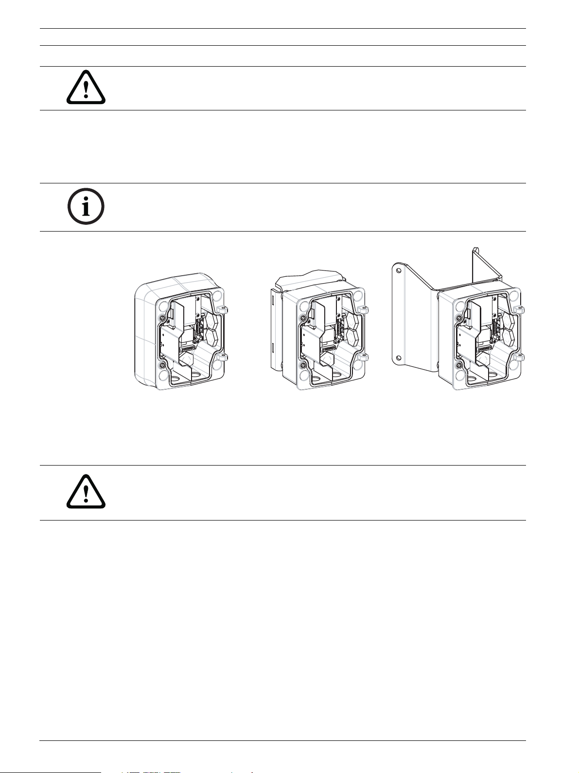
Figure 2.1 Power Supply Wall (with optional trim skirt), Mast (Pole), and Corner Mounts
1. Use the wall mount template supplied in the packaging box to locate the four mounting
holes for the Power Supply Box.
2. Drill four (4) holes for the mounting anchors. If installing outdoors, apply a weatherproof
sealant around each hole at the mounting surface.
WARNING!
A stud diameter of 6.4 mm (1/4 inch) to 8 mm (5/16 inch) able to withstand a 120 kg (265 lb)
pull-out force is recommended. The mounting material must be able to withstand this pull out
force. For example, 19-mm (3/4-inch) minimum for plywood.
3. Place the Power Supply Box into the optional Trim Skirt.
4. Secure the Power Supply Box to the mounting surface.
– For a Wall installation: Use four (4) corrosion-resistant, stainless steel studs (not
supplied). Then proceed to Step 5 below.
– For a Corner installation: Secure the Corner Plate to the wall corner using four (4)
studs (not included). Then proceed to Step 5 below.
– For a Mast or a pole installation: The metal straps included with the Mast mount
accommodate a pole with a diameter of 100–380 mm (4–15 in.). You must use a
banding tool (sold separately) for a mast or pole installation. Follow the instructions
provided with the banding tool to securely mount the Mast Plate to the pole.
Contact your Bosch Sales Representative to order Banding Tool P/N TC9311PM3T.
5. Secure the Power Supply Box to the Corner Plate or Mast Plate using the four (4) 3/8 x 13/4-inch bolts and split lock washers (supplied).
F.01U.273.797 | 5.0 | 2012.08 Installation Manual Bosch Security Systems, Inc.
Page 17
AutoDome 800 Series HD PTZ Camera Installing the Pendant Arm Wall, Corner, and Mast (Pole) Mounts | en 17
GND T XD R XD C+ C-
24 VAC
P101
P106 P105
P107
XF102 XF103
XF101
5 4 3 2 1
J103
J102
J101
(LED)
HTR DOME
24V NC 24V
GND T XD R XD C+ C-
6. Attach 3/4-inch (20-mm) NPS watertight pipe fittings (not supplied) to the bottom or
back holes of the Power Supply Box through which you will run the power, video, and
control data wires.
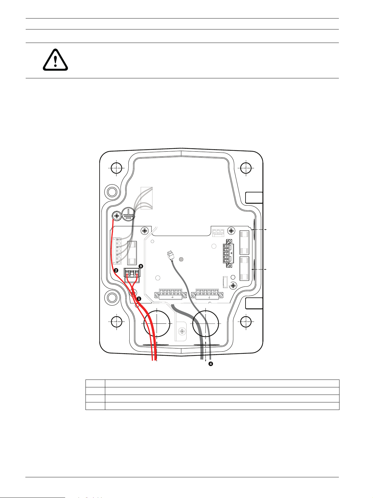
2.4 Route Wires and Attach Connectors
Power wires must be routed to the left (front) side of the power supply box through a
separate conduit. All video, control, and alarm wires must be routed through a second conduit
to the right side of the box.
If you plan to route the power through an intermediate power supply box, refer to
Section 2.5 Route Power through Intermediate Power Supply Box, page 20.
WARNING!
External interconnecting cables are to be installed in accordance to NEC, ANSI/NFPA70 (for
US application) and Canadian Electrical Code, Part I, CSA C22.1 (for CAN application) and in
accordance to local country codes for all other countries.
Branch circuit protection incorporating a 20 A, 2-pole Listed Circuit Breaker or Branch Rated
Fuses are required as part of the building installation. A readily accessible 2-pole disconnect
device with a contact separation of at least 3 mm must be incorporated.
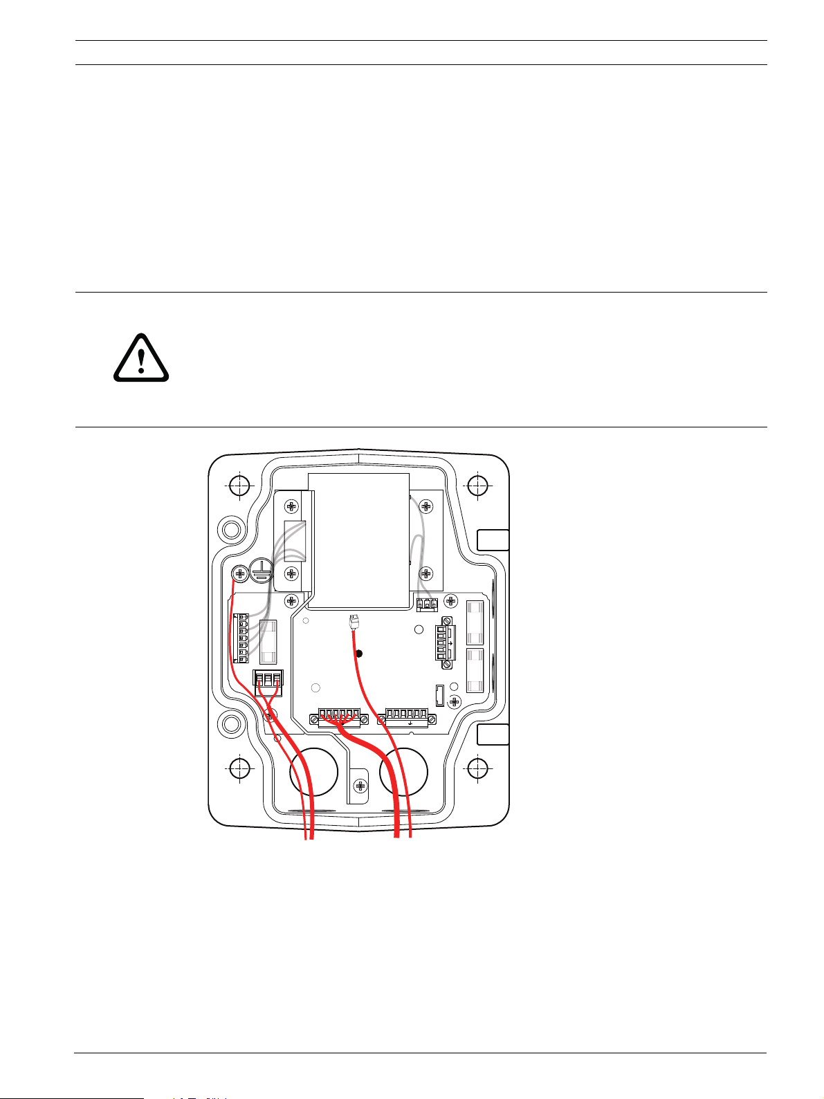
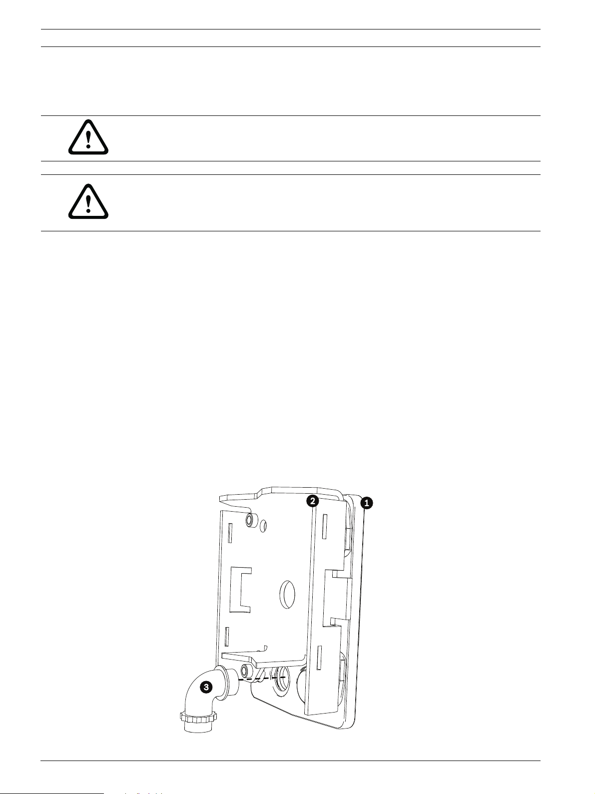
Figure 2.2 Pendant Arm Power Supply Box
1. Route all network, control, and alarm wires through the conduit fitting on the right side
of the power box. See Section 4 Cable and Wire Standards, page 51, for fiber optic
specifications and distances.
2. Route the high voltage 115/230 VAC lines through the conduit fitting on the left side of
the box. The Power Supply Box with a transformer comes with a barrier that separates
the high voltage side on the left, from the low voltage 24 VAC side on the right.
3. Cut and trim all wires with sufficient slack to reach their connector terminals in the box,
but not so long as to be pinched by or to obstruct closing the Pendant Arm. See
Figure 2.2, Page 17, above, for the connector locations.
Bosch Security Systems, Inc. Installation Manual F.01U.273.797 | 5.0 | 2012.08
Page 18
18 en | Installing the Pendant Arm Wall, Corner, and Mast (Pole) Mounts AutoDome 800 Series HD PTZ Camera
4. Attach the supplied 3-pin Power Plug to the incoming power wires. See connector P101
in Table 2.1, Page 20, for wire connections.
5. Attach an RJ45 plug to the incoming Ethernet cable. If installing a Fiber Optic model,
attach an ST fiber plug to the optic fiber cable. See Section 4 Cable and Wire Standards,
page 51, for the different methods of transmitting video and control protocols, and wire
specifications.
6. If you are connecting alarm inputs and relay outputs, attach the supplied 4-wire Alarm
Output and the 6-wire Alarm Input flying leads to the appropriate relay and alarm wires.
WIRE
1
2
3
4
WHITE
BROWN
ORANGE
GREEN
WIRE
1
2
3
4
5
6
WHITE
BROWN
ORANGE
GREEN
YELLOW
BLUE
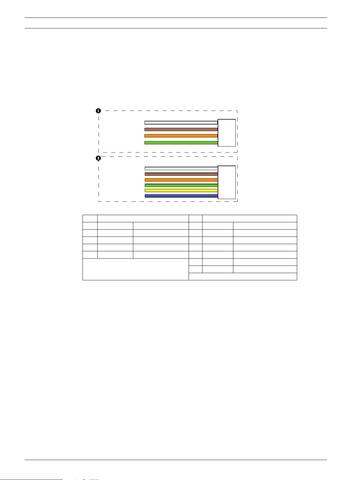
Figure 2.3 Alarm and relay connectors
1 4-pin Alarm Output Flying Lead 2 6-pin Alarm Input Flying Lead
Wire Color Description Wire Color Description
1 White Not used 1 White Alarm Input 1 (A3)
2 Brown Not used 2 Brown Alarm Input 2 (A4)
3 Orange Relay Out 1 3 Orange Not used
4 Green Relay Ground 4 Green Not used
5 Yellow Not used
6 Blue Alarm Ground (AGND)
F.01U.273.797 | 5.0 | 2012.08 Installation Manual Bosch Security Systems, Inc.
Page 19
AutoDome 800 Series HD PTZ Camera Installing the Pendant Arm Wall, Corner, and Mast (Pole) Mounts | en 19
)
P101
1 2 3
6 5 4 3 2 1 6 5 4 3 2 1
P106
XF102 XF103
XF101
J10
1
J1
(LED)
P107
5 4 3 2 1
GND TXD RXD C+ C-
P105
GND TXD RXD C+ C-
HTR DOME
24V NC 24V
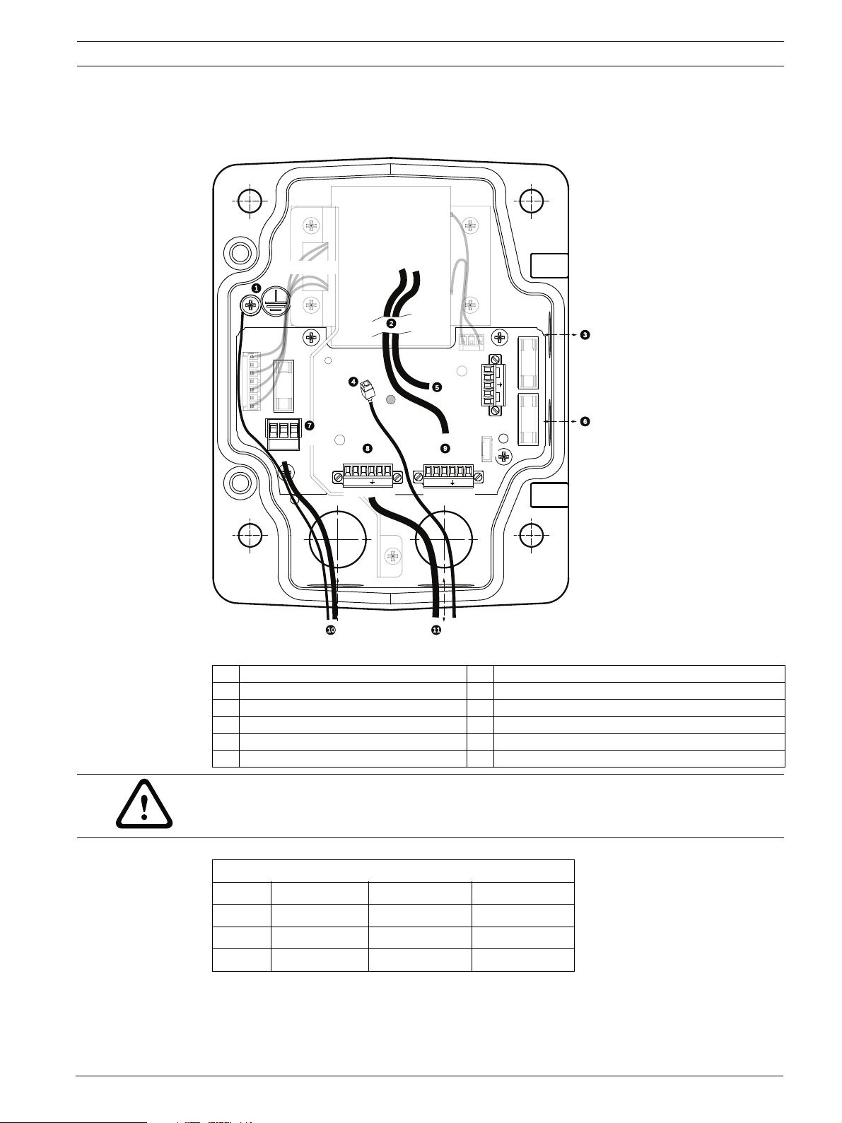
2.4.1 Power Supply Box Connections
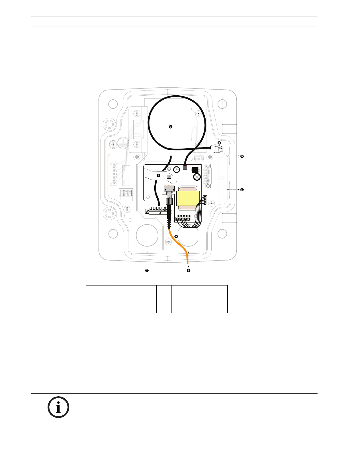
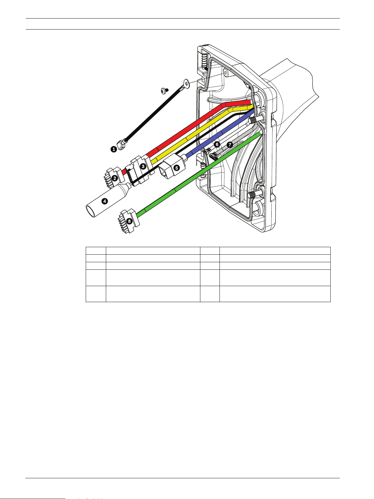
The following figure is a detailed illustration of the Pendant Arm Power Supply Box, which
includes the fuse specifications.
TRANSFORMER
(115/230VAC
MODELS
0
(FUSE
2
Figure 2.4 Pendant arm power supply box
1 Ground Screw 7 P101 Connector; Power In
2 From Harness 8 P106 Connector; Audio In
3 In/Out; 1/2 in. (15 mm) NPS Fitting 9 P105 Connector; Audio In to Dome
4 Ethernet (video and control) 10 Power In; 3/4 in. (20 mm) NPS Fitting
5 24 VAC to Dome 11 Audio In; 3/4 in. (20 mm) NPS Fitting
6 In/Out; 1/2 in. (15 mm) NPS Fitting
WARNING!
Fuse replacement by qualified service personnel only. Replace with same type fuse.
Fuse Specifications
Volts XF101 Mains XF102 Camera XF103 Heater
24 V T 5.0 A T 2.0 A T 3.15 A
115 V T 1.6 A T 2.0 A T 3.15 A
230 V T 0.8A T 2.0 A T 3.15 A
The following table lists the Power Supply Box connectors:
Bosch Security Systems, Inc. Installation Manual F.01U.273.797 | 5.0 | 2012.08
Page 20
20 en | Installing the Pendant Arm Wall, Corner, and Mast (Pole) Mounts AutoDome 800 Series HD PTZ Camera
G
P101
1 2 3
6 5 4 3 2 1
6 5
6 5 4 3 2 1
06P105
P107
XF102 XF103
XF101
5 4 3 2 1
J10
J
1
(LED)
VG4-PSU1 / VG4-PSU2
HTR DOME
)
24V NC 24V
No. Connector Pin 1 Pin 2 Pin 3 Pin 4 Pin 5 Pin 6
Ground Grounding Screw
P101 115/230 VAC or
Line NC Neutral
24 VAC Power In
P105 Data/Audio Audio Audio Earth
Not Used
Ground
P106 Not Used
P107 24 VAC Power
(Arm Harness)
Dome
24 VAC
Dome
24 VAC
Earth
Ground
Heater
(24 VAC)
Heater
(24 VAC)
Tab le 2 .1 Power Supply Box Connections
2.5 Route Power through Intermediate Power Supply Box
You may route the main power supply through a VG4-PSU1 (120 V transformer) or through a
VG4-PSU2 (230 V transformer) Power Supply Box before connecting the power to a VG4-PA0
(24 V, no transformer) Power Supply Box. The main issue with this configuration is that the 5pin power out connector from the VG4-PSU1 or VG4-PSU2 does not match to the 3-pin power
input of the VG4-PA0 power supply. The illustration below depicts:
– A VG4-PSU1/VG4-PSU2 Power Supply Box.
– The main power supply connected to the P101 connector and to the grounding screw.
– The 24 VAC power out wire connected to the P107 heater power connectors.
10
2
FUSE
FUSE)
P1
GND XD XD C+ C-
ND
XD
XD C+ C-
Figure 2.5 VG4-PSU1/VG4-PSU2 Power Supply Box
F.01U.273.797 | 5.0 | 2012.08 Installation Manual Bosch Security Systems, Inc.
Page 21
AutoDome 800 Series HD PTZ Camera Installing the Pendant Arm Wall, Corner, and Mast (Pole) Mounts | en 21
P101
24V NC 24V
1 2 3
1 120/230 VAC Power In 5 Transformer
2 Ground Wire 6 In/Out Conduit (1/2 in. [15 mm] NPS Fitting
3 P101 Connector 7 24 VAC Power Out to VG4-PA0
4 P107 Connector
To properly wire the incoming high voltage and the outgoing low voltage lines, refer to this
table:
No. Connector Pin 1 Pin 2 Pin 3 Pin 4 Pin 5 Pin 6
Ground Grounding Screw
P101 115/230 VAC Power In Line NC Neutral
P107 24 VAC Power
Tab le 2 .2 VG4-PSU1/VG4-PSU2 Power Supply Box Connections
Out Earth
Ground
Heater
(24 VAC)
Heater
(24 VAC)
1. Route the high voltage 115/230 VAC lines through the conduit fitting on the left side of
the box. The Power Supply Box with a transformer comes with a barrier that separates
the high voltage side on the left, from the low voltage 24 VAC side on the right.
2. Cut and trim the high voltage 115/230 VAC power and ground wires with sufficient slack
to reach their connector terminal in the box, but not so long as to be pinched by or to
obstruct closing the cover door.
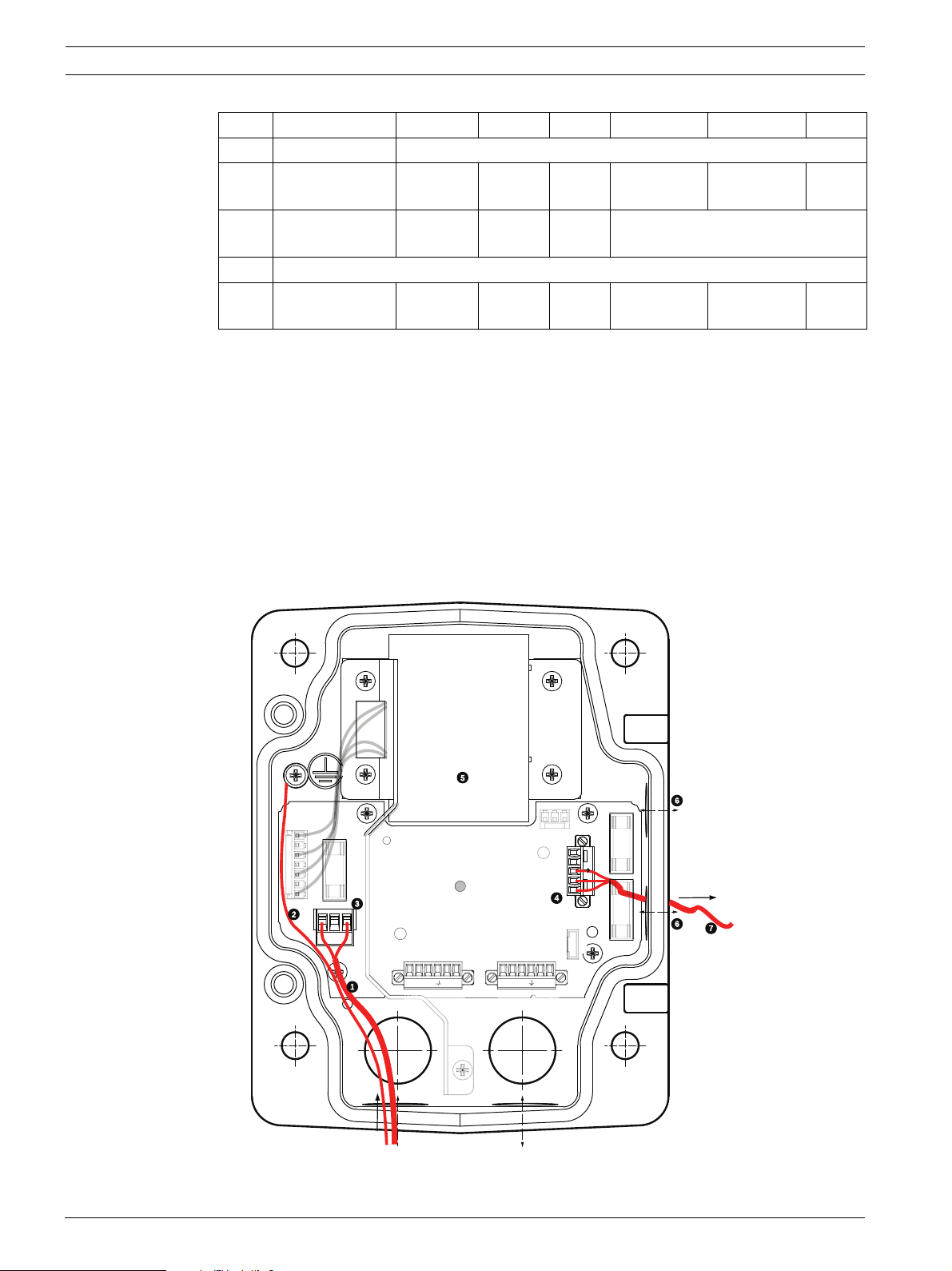
3. Attach the supplied 3-pin power plug to the incoming high voltage power wires in the
box. Refer to connector P101 in Table 2.2, Page 21 and to the image below for an
illustration of these connections:
Figure 2.6 Incoming 115/230 VAC power supply
4. Attach the ground wire to the grounding screw.
5. Connect three wires to the P107 Power Out connector to route the 24 VAC power supply
to the VG4-PA0 Power Supply Box.
a. Connect the first wire to pin 5 (HN: Heater Neutral) connector.
b. Connect the second wire to pin 4 (HL: Heater Line) connector.
c. Connect the third wire to pin 3 (Earth Ground) connector.
Refer to connector P107 in Table 2.2 and to the image below for an illustration of
these connections:
P107
HTR DOME
5 4 3 2 1
Figure 2.7 Outgoing 24 VAC power supply
Bosch Security Systems, Inc. Installation Manual F.01U.273.797 | 5.0 | 2012.08
Page 22
22 en | Installing the Pendant Arm Wall, Corner, and Mast (Pole) Mounts AutoDome 800 Series HD PTZ Camera
XD
XD
C
G
XD
C
P101
1 2 3
6 5 4 3 2 1
6 5
6 5 4 3 2 1
P107
XF102 XF103
XF101
5 4 3 2 1
J10
J
(LED)
HTR DOME
)
)
24V NC 24V
WARNING!
Ensure that you connect the outgoing power supply wires to the P107 heater connectors (HN
and HL). The heater power (XF103) fuse can handle a higher amperage (3.15 A) than the
camera power (XF102) fuse (2.0 A).
6. Route the 24 VAC outgoing power supply wires into the VG4-PA0 power supply box
through the conduit fitting on the left side of the box.
7. Cut and trim the 24 VAC power and ground wires with sufficient slack to reach their
connector terminal in the box, but not so long as to be pinched by or to obstruct closing
the cover door.
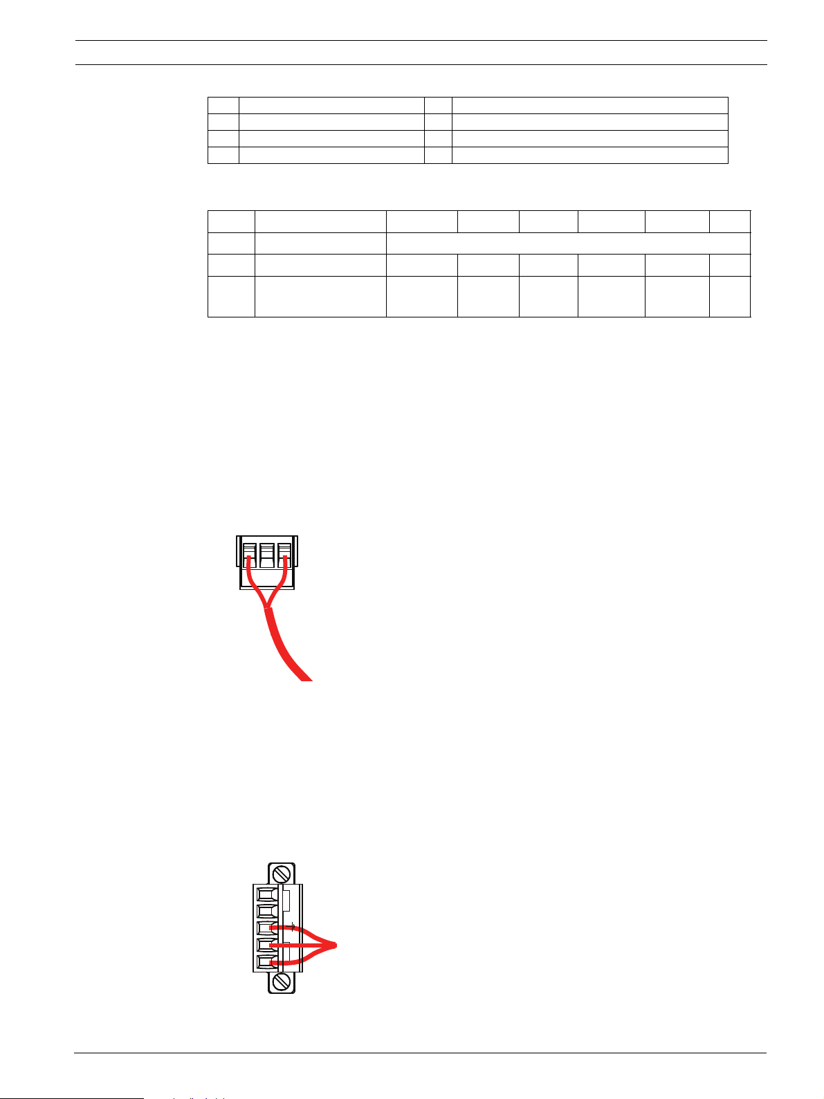
8. Attach the supplied 3-pin power plug to the incoming 24 VAC power wires in the box, as
illustrated below.
101
2
FUSE
FUSE)
FUSE
P106 P105
GND
ND
XD
+ C-
+ C-
Figure 2.8 VG4-PA0 Power Supply Box
1 Incoming 24 VAC Power Supply Wires (from VG4-PSU1/VG4-PSU2 power supply box)
2Ground Wire
3 P101 Connector
4 Ethernet (Video and Control)
9. Follow the instructions in Section 2.6 Attach Pendant Arm to Power Supply Box, page 22, to
continue the installation.
2.6 Attach Pendant Arm to Power Supply Box
The bottom hinge pin of the Pendant Arm is provided with a Hinge Pin Stop to hold the hinge
open while attaching the arm to the Power Supply Box.
F.01U.273.797 | 5.0 | 2012.08 Installation Manual Bosch Security Systems, Inc.
Page 23
AutoDome 800 Series HD PTZ Camera Installing the Pendant Arm Wall, Corner, and Mast (Pole) Mounts | en 23
1. Compress the bottom hinge pin by pushing the pin lever downward and rotating it
behind the Hinge Pin Stop.
Figure 2.9 Pendant Arm to Power Box Hinge Alignment
2. Open the top hinge by pushing its pin lever up and holding it.
NOTICE! Both Hinge Pins must be fully compressed to open (unlock) the hinges of the
Pendant Arm and before proceeding to the next step.
3. While continuing to hold the top hinge pin open and align the top and bottom hinges of
the Pendant Arm to their mating points on the Power Supply Box. See Figure 2.9, above,
for an illustration.
4. Once you have the hinges aligned, release the top hinge pin to engage its mating hinge on
the power box. Then release the bottom hinge pin from the Hinge Pin Stop to lock the
Pendant Arm to the Power Supply Box.
WARNING!
Serious injury or death can occur if the hinge pins of the Pendant Arm are not fully engaged
(locked) to the Power Supply Box. Exercise caution before releasing the Pendant Arm.
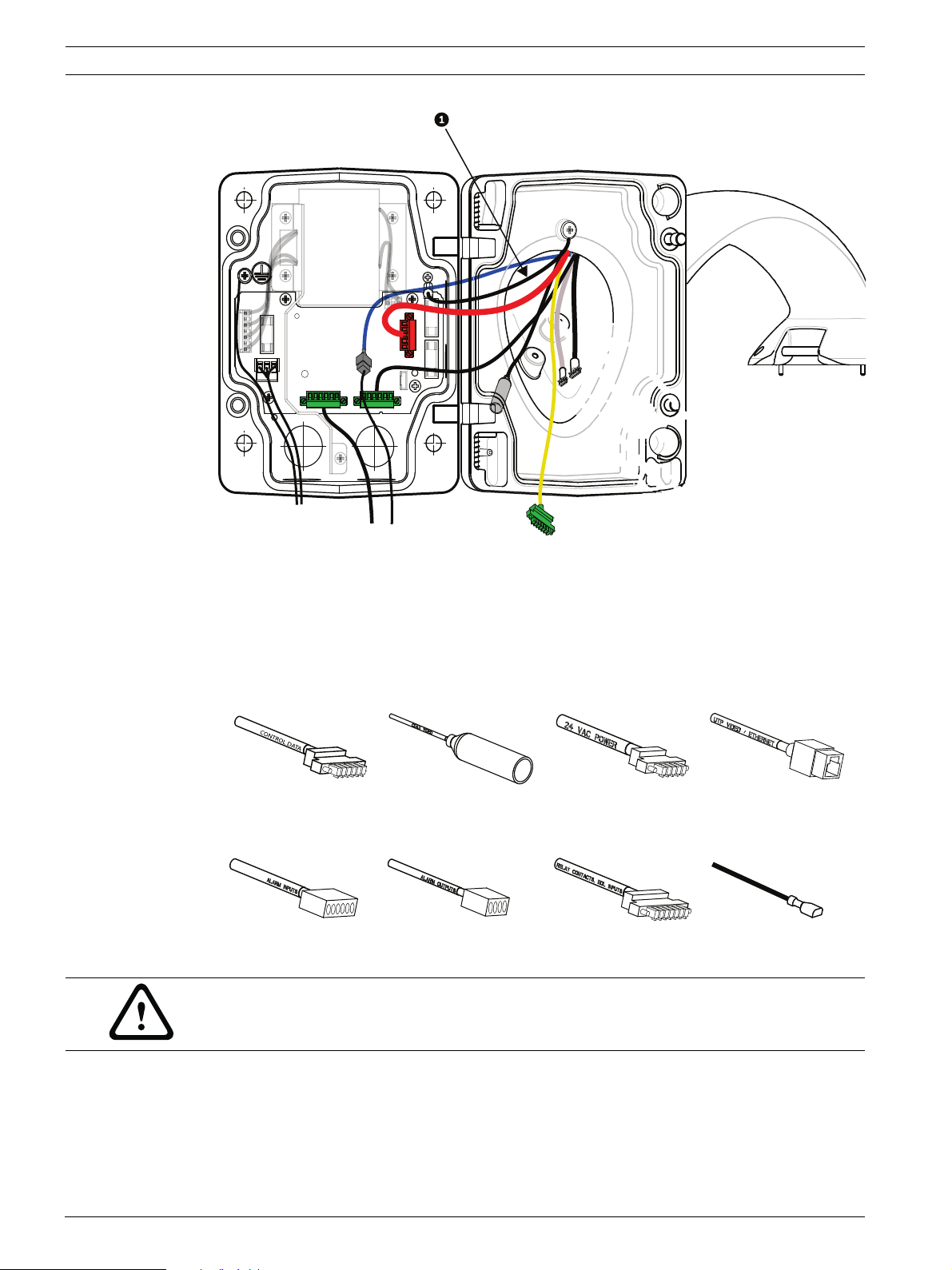
2.7 Make Connections in Power Supply Box
Refer to Table 2.2, Page 21 to locate the various connectors in the power supply box and make
the following connections detailed below.
Bosch Security Systems, Inc. Installation Manual F.01U.273.797 | 5.0 | 2012.08
Page 24
24 en | Installing the Pendant Arm Wall, Corner, and Mast (Pole) Mounts AutoDome 800 Series HD PTZ Camera
1 2 3
Figure 2.10 Pendant Arm connections to Power Supply Box
1. Attach the earth ground wire (item 1 in the illustration above) to the grounding screw on
the left side of the power box.
2. Connect the 6-pin Control/Audio cable, installed previously, to its mating connector P106
in the power box.
3. Connect the 6-pin Control to Dome Plug from the Pendant Connector Harness to its
matting connector P105 in the power box.
Control/Audio
Coax Video
(not used)
24 VAC Power Ethernet Video and
Control
Alarm Inputs Alarm Outputs Relays Grounding Strap
WARNING!
Do not connect the RJ45 connector unless using UTP video or Ethernet.
4. Connect the 5-pin, 24 VAC to Dome Plug from the Pendant Connector Harness to its
corresponding color mating connector P107 on the right side of the box.
5. To connect alarm Inputs and the alarm output, connect the 4-pin Alarm Out and the 6-pin
Alarm In connectors from the Pendant Connector Harness to their mating connectors,
installed previously, to the incoming alarm wires.
F.01U.273.797 | 5.0 | 2012.08 Installation Manual Bosch Security Systems, Inc.
Page 25
AutoDome 800 Series HD PTZ Camera Installing the Pendant Arm Wall, Corner, and Mast (Pole) Mounts | en 25
)
V
6. Connect the 3-pin Power In Plug, installed previously, to its matting connector P101 on
the left side of the box.
7. If installing a Fiber Optic model attach the incoming ST fiber plug, installed previously, to
its mating connector on the Fiber Optic Module in the power supply box. Then attach the
Ethernet cable to its mating connector from the Pendant Connector Harness. See
Section 4 Cable and Wire Standards, page 51 for fiber optic specifications.
(GND)
FUSE
24V NC 24
GND TXD RXD C+ C-
Figure 2.11 Optional Fiber Optic Module
FUSE)
FUSE)
1 Transformer 5 In/Out
2 Ethernet to Dome 6 ST Connector (Fiber)
3In/Out 7Power In
4 From Arm Harness 8 Data In/Out
8. Connect the incoming RJ45 connector, installed previously, to its mating connector from
the Pendant Connector Harness. See Section 4 Cable and Wire Standards, page 51 for
connections and specifications.
9. Attach the grounding strap of the Pendant Arm to the Power Supply Box. See Figure 2.10,
Page 24.
10. After making the harness connections to the Power Supply Box, rotate the Pendant Arm
to close and seal the Power Supply Box and tighten the two (2) captive screws to
10-12 N-m (90-105 in.-lbs).
11. Refer to Section 2.9 Attach Pendant to Arm and Tighten, page 31, to continue the
AutoDome Installation procedure.
NOTICE! After all wiring is complete, close the cover door and tighten the two (2) captive
screws on the cover door to 10-12 N-m (90-105 in.-lbs) to ensure the Power Supply Box is
watertight.
Bosch Security Systems, Inc. Installation Manual F.01U.273.797 | 5.0 | 2012.08
Page 26
26 en | Installing the Pendant Arm Wall, Corner, and Mast (Pole) Mounts AutoDome 800 Series HD PTZ Camera
2.8 Installing the VG4-A-ARMPLATE
This section provides instructions to install a wall, corner, or mast mount with the VG4-AARMPLATE Mounting Plate instead of a Power Supply Box.
CAUTION!
You must route the main power supply through a 120/230 VAC transformer (VG4-PSU1 or
VG4-PSU2 power supply box) before connecting the power to a 24 VAC AutoDome.
WARNING!
A stud diameter of 6.4 mm (1/4 inch) to 8 mm (5/16 inch) able to withstand a 120 kg (265 lb)
pull-out force is recommended. The mounting material must be able to withstand this pull out
force. For example, 19-mm (3/4-inch) minimum for plywood.
1. For a Corner installation:
a. Secure the Corner Plate to the wall corner using four (4) studs (not included).
b. Secure the Mounting Plate to the Corner Plate using the four (4) 3/8 x 1-3/4-inch
bolts and split lock washers (supplied).
2. For a Mast or pole installation:
The metal straps included with the Mast mount accommodate a pole with a diameter of
100–380 mm (4–15 in.). You must use a banding tool (sold separately) for a mast or pole
installation. In addition, you must obtain a 3/4 in. (20-mm) right angle conduit connector
through which you route the wires that connect to the pendent arm.
a. Follow the instructions provided with the banding tool to securely mount the Mast
Plate to the pole. Contact your Bosch Sales Representative to order Banding Tool
P/N TC9311PM3T.
b. Secure the Mounting Plate to the Mast Plate using the four (4) 3/8 x 1-3/4-inch bolts
and split lock washers (supplied).
c. Remove one of the rubber gaskets from the Mounting Plate.
d. Once the Mounting Plate (item 1, below) is attached to the Mast Plate (item 2),
connect the right angle conduit (item 3) to the Mounting Plate through the empty
conduit hole as shown below:
F.01U.273.797 | 5.0 | 2012.08 Installation Manual Bosch Security Systems, Inc.
Page 27

AutoDome 800 Series HD PTZ Camera Installing the Pendant Arm Wall, Corner, and Mast (Pole) Mounts | en 27
3. Ensure that the mounting plate is secure.
2.8.1 Attach the Pendant Arm to the Mounting Plate
The bottom hinge pin of the Pendant Arm is provided with a Hinge Pin Stop to hold the hinge
open while attaching the arm to the Mounting Plate.
1. Compress the bottom hinge pin by pushing the pin lever downward and rotating it
behind the Hinge Pin Stop.
Figure 2.12 Connect Pendant Arm to Mounting Plate
2. Open the top hinge by pushing its pin lever up and holding it.
Note: Both Hinge Pins must be fully compressed to open (unlock) the hinges of the
Pendant Arm and before proceeding to the next step.
3. While continuing to hold the top hinge pin open, align the top and bottom hinges of the
Pendant Arm to their mating points on the Mounting Plate. See Figure 2.12, above, for an
illustration.
4. Once you have the hinges aligned, release the top hinge pin to engage its mating hinge on
the Mounting Plate. Then release the bottom hinge pin from the Hinge Pin Stop to lock
the Pendant Arm to the Mounting Plate.
2.8.2 Route and Connect Wires to a Power Supply Box
The illustration below depicts the power and control cables connected to the Pendant Arm:
Bosch Security Systems, Inc. Installation Manual F.01U.273.797 | 5.0 | 2012.08
Page 28
28 en | Installing the Pendant Arm Wall, Corner, and Mast (Pole) Mounts AutoDome 800 Series HD PTZ Camera
Figure 2.13 Pendant Arm Cables
Cable Cable Cable Cable
1 Grounding Strap (black) 5 Ethernet Video and Control (blue)
2 24 VAC Power (red) 6 Alarm Outputs (white)
3 Relay Contacts (yellow)
7 Alarm Inputs (gray)
(not used)
4 Coax Video (black)
8Audio In (green)
(not used)
1. Route all incoming wires through one of the conduits at the bottom of the Mounting
Plate. For a mast mount, route all wires through the right-angle conduit.
2. Attach the water-tight plug to the other conduit.
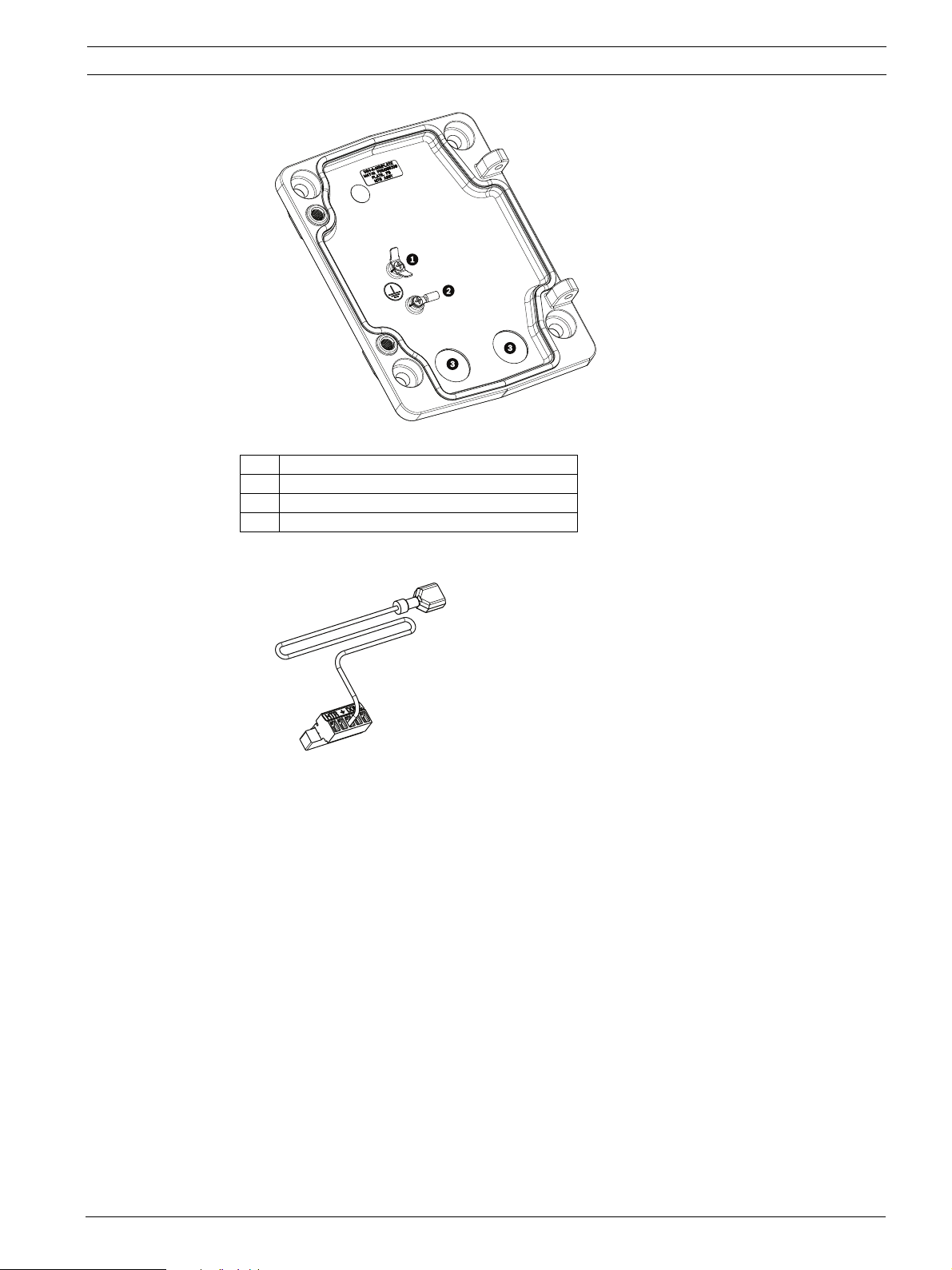
3. Attach the grounding spade terminal (item 1, below) to one of the spade terminals inside
the Mounting Plate.
F.01U.273.797 | 5.0 | 2012.08 Installation Manual Bosch Security Systems, Inc.
Page 29
AutoDome 800 Series HD PTZ Camera Installing the Pendant Arm Wall, Corner, and Mast (Pole) Mounts | en 29
Figure 2.14 Mounting Plate - Inside Detail
Ref. Description
1 Grounding lug with two spade terminals
2 Earth ground lug with crimp ring terminal
3 Wire input conduit holes
4. Connect the incoming 24 VAC power wires to the 5-pin, 24 VAC Power In mating
connector (supplied with the Mounting Plate kit) for the Dome and for the Heater.
5. Attach the grounding spade from the 5-pin mating connector (item 1, Figure 2.14) to the
other spade terminal inside the mounting plate.
6. Attach the 5-pin Power In mating connector to the 24 VAC Power cable (cable 2)
connected to the pendant.
7. Connect the incoming RJ45 video connector, installed previously, to the Ethernet cable
(cable 5). Refer to Section 4 Cable and Wire Standards, page 51, for detailed wire and
connection information.
8. Connect the outgoing alarm wires to the flying leads coming from the 4-pin Alarm
Outputs cable (cable 6).
9. Connect the incoming alarms wires to the flying leads coming from the 6-pin Alarm Inputs
cable (cable 7).
10. Connect the incoming Audio In wires to the 6-pin mating connector supplied with the
VG4-A-ARMPLATE kit. Ensure that the 100 Ω resistor has been removed between C(Audio -) and the C+ (Audio +) terminals.
Refer to Section 4 Cable and Wire Standards, page 51, for detailed wire and connection
information.
11. Attach the 6-pin Audio In mating connector to the Audio In (cable 8) cable.
Bosch Security Systems, Inc. Installation Manual F.01U.273.797 | 5.0 | 2012.08
Page 30
30 en | Installing the Pendant Arm Wall, Corner, and Mast (Pole) Mounts AutoDome 800 Series HD PTZ Camera
12. Connect the Earth ground wire, if available, to the crimp ring terminal inside the
Mounting Plate. Refer to Figure 2.14 above.
Note: The Earth ground is not provided with the VG4-A-ARMPLATE kit; it is a ground
connection made at the installed location.
13. After making the harness connections to the Mounting Plate, rotate the Pendant Arm to
close and tighten the two (2) captive screws to 10-12 N-m (90-105 in.-lbs).
14. Refer to Section 2.9 Attach Pendant to Arm and Tighten, page 31, to continue the
AutoDome Installation procedure.
NOTICE! After all wiring is complete, close the cover door and tighten the two (2) captive
screws on the cover door to 10-12 N-m (90-105 in.-lbs).
F.01U.273.797 | 5.0 | 2012.08 Installation Manual Bosch Security Systems, Inc.
Page 31

AutoDome 800 Series HD PTZ Camera Installing the Pendant Arm Wall, Corner, and Mast (Pole) Mounts | en 31
2.9 Attach Pendant to Arm and Tighten
CAUTION!
The bubble is packaged with a protective plastic sheet. It is recommended that the bubble
remain stored this way until it is ready to install. Limit handling the bubble, as any scratches
can quickly affect visibility.
NOTICE! Before attaching the AutoDome Pendant, visually inspect the dome and arm
connectors for any blocked pin holes or bent pins.
1. Tilt the bottom of the dome toward the pendant arm base and place the mounting hook,
located on top of the dome housing, over the recessed hinge pin of the arm.
a
b
Figure 2.15 Attach Pendant to Arm
1Tilt up.
2 Hook and drop.
2a Recessed Hinge Pin
2b Dome Connector
3 Rotate down to engage dome connector.
4 Tighten the two (2) mounting screws to a minimum torque of 10-12 N-m (90-105 in.-lbs).
2. Drop the dome housing down slightly to engage the dome housing hook on the Pendant
Arm hinge pin, allowing the dome to rotate around the pin.
3. Rotate the dome housing down to a vertical position and gently push upward to engage
the connector on top of the dome housing.
Bosch Security Systems, Inc. Installation Manual F.01U.273.797 | 5.0 | 2012.08
Page 32

32 en | Installing the Pendant Arm Wall, Corner, and Mast (Pole) Mounts AutoDome 800 Series HD PTZ Camera
CAUTION!
If you feel any resistance when rotating the dome housing or when engaging the connector,
stop immediately and start over.
4. Hold the Pendant housing in position while tightening the two (2) 5-mm Allen head
mounting screws on top of the housing to 10-12 N-m (90-105 in.-lbs).
CAUTION!
You must tighten the two mounting screws to a minimum torque of 10-12 N-m (90-105 in.-lbs)
to ensure a proper seal between the arm and the housing.
F.01U.273.797 | 5.0 | 2012.08 Installation Manual Bosch Security Systems, Inc.
Page 33

AutoDome 800 Series HD PTZ Camera Installing Roof Parapet and Pipe Mounts | en 33
3 Installing Roof Parapet and Pipe Mounts
3.1 Unpacking
This equipment should be unpacked and handled with care. If an item appears to have been
damaged in shipment, notify the shipper immediately.
Verify that all the parts listed in the product's Parts List below are included. If any items are
missing, notify your Bosch Security Systems Sales or Customer Service Representative. See
Section 1.4 Customer Support and Service, page 13 for Customer Support and Service contact
information.
The original packing carton is the safest container in which to transport the unit and must be
used if returning the unit for service. Save it for possible future use.
3.1.1 Parts List
The following table lists the parts included with the Roof Parapet and Pipe mount packages:
Mount Kit Options Part Numbers
Parapet (Roof) Mount and
Pipe Mount with one of the following Power Supply Boxes:
– Power Supply Box with 120 VAC transformer
or 230 VAC transformer
Optional Flat Roof Mount Adapter for VGA-ROOF-MOUNT Mount (not
included)
Pipe Mount with one of the following Power Supply Boxes: VG4-A-9543
– Power Supply Box with transformer 120 VAC
or 230 VAC transformer
Trim Skirt for Power Supply Box (optional) VG4-A-TSKIRT
Fiber Optic Ethernet Media Converter kit VG4-SFPSCKT
VGA-ROOF-MOUNT
VG4-A-9543
VG4-A-PSU1
VG4-A-PSU2
LTC 9230/01
VG4-A-PSU1
VG4-A-PSU2
3.1.2 Description
This chapter details how to install an AutoDome to a Roof Parapet or to a Pipe mount. Any
differences to the installation between these two mounting systems are noted. See
Section 2 Installing the Pendant Arm Wall, Corner, and Mast (Pole) Mounts, page 14 for this type
of application.
The VG4-A-9230 Series are stationary mounts intended for rooftop parapet vertical walls. They
are made of light weight aluminum with a corrosion-resistant finish and are used for all Bosch
AutoDome Camera systems up to a rated load of 29 kg (64 lb). These mounts can be fitted to
the inside or outside of parapet walls and can swivel for ease of positioning and for servicing
the AutoDome.
3.1.3 Tools Required
– 5 mm Allen wrench (supplied)
– Small straight blade screwdrivers ~ 2.5 mm (0.1 in.) – 3.1 mm (1/8 in.)
– Medium straight blade screwdriver
– No. 1 and No. 2 Phillips screwdrivers
– Socket wrench and 9/16 in. socket
–Pipe Wrench
– Barrel connector (if installing a fiber optic model)
Bosch Security Systems, Inc. Installation Manual F.01U.273.797 | 5.0 | 2012.08
Page 34

34 en | Installing Roof Parapet and Pipe Mounts AutoDome 800 Series HD PTZ Camera
3.2 Pre-installation Check List
1. Determine the location and distance for the power supply box based on its voltage and
current consumption. See Section 4 Cable and Wire Standards, page 51 for wiring
information and distances.
2. Use only UL listed liquid tight strain reliefs for conduits to the Power Supply Box to
ensure that water cannot enter the box. You must use water tight conduits and fittings to
meet NEMA 4 standards.
NOTICE! Power and I/O cabling must be routed separately inside different permanently
earthed metal conduits.
3. Install all rough wiring including: power, Ethernet, alarms I/O, relay I/O, and fiber optic
cabling. See Section 4 Cable and Wire Standards, page 51 for video and control protocol
methods.
WARNING!
External interconnecting cables are to be installed in accordance to NEC, ANSI/NFPA70 (for
US application) and Canadian Electrical Code, Part I, CSA C22.1 (for CAN application) and in
accordance to local country codes for all other countries.
Branch circuit protection incorporating a 20 A, 2-pole Listed Circuit Breaker or Branch Rated
Fuses are required as part of the building installation. A readily accessible 2-pole disconnect
device with a contact separation of at least 3 mm must be incorporated.
4. Choose the appropriate AutoDome model for the environment in which it will be used.
5. Choose the appropriate mounting kit to use depending on the location of the AutoDome:
Parapet (Roof) mount or the Pipe mount.
CAUTION!
Select a rigid mounting location to prevent excessive vibration to the AutoDome camera.
3.3 Mount Power Supply Box
Before mounting the Power Supply Box decide if you will be wiring the box through the holes
in the bottom or back of the box. If wiring the box through the back, move the two (2) seal
plugs to the bottom holes before mounting.
NOTICE! Use 3/4-inch NPS (20-mm) fittings for the holes on the bottom and back of the box.
Use 1/2-inch NPS (15-mm) fittings for the side holes. See Section 3.1.1 Parts List, page 33, for
an illustration.
F.01U.273.797 | 5.0 | 2012.08 Installation Manual Bosch Security Systems, Inc.
Page 35

AutoDome 800 Series HD PTZ Camera Installing Roof Parapet and Pipe Mounts | en 35
Figure 3.1 Wall Mount Power Supply with Optional Trim Skirt
1. Use the wall mount template supplied in the packaging box to locate the four (4)
mounting holes for the Power Supply Box.
2. Drill four (4) holes for the mounting anchors. If installing outdoors, apply a weatherproof
sealant around each hole at the mounting surface.
3. Place the Power Supply Box into the optional Trim Skirt.
4. Secure the Power Supply Box to the wall using four (4) corrosion-resistant stainless steel
studs (not included).
NOTICE! A stud diameter of 6.4 mm (1/4 in.) or 8 mm (5/16 in.), able to withstand a 120 kg
(265 lb) pull-out force is recommended.
5. Attach the 3/4 in. (20 mm) watertight pipe fittings (not supplied) to the holes of the
Power Supply Box through which you will run the power, video, and control data wires.
Bosch Security Systems, Inc. Installation Manual F.01U.273.797 | 5.0 | 2012.08
Page 36

36 en | Installing Roof Parapet and Pipe Mounts AutoDome 800 Series HD PTZ Camera
)
)
)
3.3.1 Attach Cover Door
1. Compress the bottom hinge pin by pushing the pin lever down and then rotate it behind
the Hinge Pin Stop. The power box Cover Door provides a Hinge Pin Stop to hold the
bottom hinge open while attaching the door.
o
90
HTR DOME
FUSE
FUSE
FUSE
24V NC 24V
GND T XD R XD C+ C- GND T XD R XD C+ C-
Figure 3.2 Align Cover Door Hinge to Power Box
1 Power Supply Box 5 Hold Hinge Pin Open
2 Cover Door 6 Open Position
3 Align Top Hinge 7 Hinge Pin Stop
4 Align Bottom Hinge
2. Open the top hinge by pushing its pin lever outward and holding it open.
Note: Both Hinge Pins must be fully compressed to open (unlock) the female hinges of
the Cover Door before proceeding to the next step.
3. While holding the top hinge pin open, position the Cover Door to the Power Supply Box
and align its hinges.
4. When the hinges are aligned, release the top hinge pin to engage its mating hinge on the
power box. Then release the bottom hinge pin from the Hinge Pin Stop to complete
attaching the cover door to the Power Supply Box.
NOTICE! After all wiring is complete, close the cover door and tighten the two (2) captive
screws on the cover door to 10-12 N-m (90-105 in.-lbs) to ensure the Power Supply Box is
watertight.
F.01U.273.797 | 5.0 | 2012.08 Installation Manual Bosch Security Systems, Inc.
Page 37

AutoDome 800 Series HD PTZ Camera Installing Roof Parapet and Pipe Mounts | en 37
GND TXD RXD C+ C-GND TXD RXD C+ C-
P101
P106 P105
P107
XF102 XF103
XF101
5 4 3 2 1
J10
J101
(LED)
HTR DOME
24V NC 24V
)
)
)
3.4 Route Wires and Attach Connectors
Power wires must be routed to the left (front) side of the Power Supply Box through a
separate conduit. All video, control, and alarm wires must be routed through a second conduit
to the right side of the box. See Section 4 Cable and Wire Standards, page 51 for methods of
transmitting video and data, and for wire specifications.
WARNING!
External interconnecting cables are to be installed in accordance to NEC, ANSI/NFPA70 (for
US application) and Canadian Electrical Code, Part I, CSA C22.1 (for CAN application) and in
accordance to local country codes for all other countries.
Branch circuit protection incorporating a 20 A, 2-pole Listed Circuit Breaker or Branch Rated
Fuses are required as part of the building installation. A readily accessible 2-pole disconnect
device with a contact separation of at least 3 mm must be incorporated.
There are two possible methods to route the video, control, and alarm wires:
– One is to route the power, ethernet, and alarm wires through the conduit fitting on the
right (front) side of the Power Supply Box and out to the AutoDome Interface Board.
2
FUSE
FUSE
FUSE
Figure 3.3 VG4-A-PSU1 or VG4-A-PSU2 Power Supply Box
1 120 VAC/230 VAC Power In 5 Ethernet Video and Control Wire
2 P101 Connector 6 24 VAC Power Out
3 Ground Connection 7 P107 Connector
4 Transformer
– The second method is to bypass the Power Supply Box and route the ethernet and alarm
wires directly to the Interface Board. You connect only the power wires inside the Power
Supply Box.
Bosch Security Systems, Inc. Installation Manual F.01U.273.797 | 5.0 | 2012.08
Page 38

38 en | Installing Roof Parapet and Pipe Mounts AutoDome 800 Series HD PTZ Camera
GND TXD RXD C+ C-GND TXD RXD C+ C-
P101
P106 P105
P107
XF102 XF103
XF101
5 4 3 2 1
J10
J101
(LED)
HTR DOME
24V NC 24V
)
)
)
BNC
J102
P107 P101
P102
P103
P104
P106
J101
AGND
A7
A6
A5
A4
A3
AGND
OUT 3
OUT 2
OUT 1
P105
2
FUSE
FUSE
FUSE
Figure 3.4 VG4-A-PSU1 or VG4-A-PSU2 Power Supply Box Connected to Pipe Interface Board
1 120 VAC/230 VAC Power In 7 P101 Connector
2 P101 Connector 8 P107 Connector
3 Ground Connection 9 24 VAC Power In (to AutoDome)
4 Transformer 10 Earth Ground
5 24 VAC Power Out 11 24 VAC Power In (to AutoDome)
6 P107 Connector 12 24 VAC Power In (to Heater)
VG4-A-PSU1/VG4-A-PSU2 Pipe Interface Board
13 24 VAC Power In (to Heater)
14 AutoDome Power
15 Heater Power
F.01U.273.797 | 5.0 | 2012.08 Installation Manual Bosch Security Systems, Inc.
Page 39

AutoDome 800 Series HD PTZ Camera Installing Roof Parapet and Pipe Mounts | en 39
3.4.1 Wiring the Power Supply Box
1. Route the high voltage 115/230 VAC lines through the conduit fitting on the left side of
the box.
NOTICE! The Power Supply Box with transformer comes with a barrier that separates the high
voltage side on the left from the low voltage 24 VAC side on the right.
2. Cut and trim the high voltage 115/230 VAC power and ground wires with sufficient slack
to reach their connector terminal in the box, but not so long as to be pinched by or to
obstruct closing the Cover Door. See Section 3.1.1 Parts List, page 33, for connector
location.
3. Attach the supplied 3-pin Power Plug to the incoming high voltage power wires in the
box. See connector P101 in Table 3.1, Page 42.
4. Route the low power 24 VAC wires from the right side of the Power Supply Box out to
where the AutoDome will be mounted. Attach the supplied 5-pin 24 VAC Dome plug to
the wire ends inside the box. See connector P107 in Table 3.1, Page 42.
5. Route the Ethernet cable out to where the AutoDome will be mounted. See
Section 4 Cable and Wire Standards, page 51 for fiber optic specifications.
NOTICE! All ethernet and alarm wires either pass through the Power Supply Box or by-pass it
and connect directly to the Pipe Interface Board.
3.4.2 Wiring the Fiber Optic Model
If installing a Fiber Optic model, bring the fiber optic cable into the right side of the
power supply box.
Bosch Security Systems, Inc. Installation Manual F.01U.273.797 | 5.0 | 2012.08
Page 40

40 en | Installing Roof Parapet and Pipe Mounts AutoDome 800 Series HD PTZ Camera
)
V
(GND)
FUSE
24V NC 24
GND TXD RXD C+ C-
1Transformer 5In/Out
2 Ethernet to Dome 6 ST Connector (Fiber)
3In/Out 7Power In
4 From Arm Harness 8 Data In/Out
FUSE)
FUSE)
F.01U.273.797 | 5.0 | 2012.08 Installation Manual Bosch Security Systems, Inc.
Page 41

AutoDome 800 Series HD PTZ Camera Installing Roof Parapet and Pipe Mounts | en 41
T
T
G
C
C
P101
1 2 3
6 5 4 3 2 1
P107
XF102 XF103
XF101
5 4 3 2 1
J10
1
J1
(LED)
6 5
G
C
C
HTR DOME
24V NC 24V
3.4.3 Power Supply Box Connections
The following figure is a detailed illustration of the Roof or Pipe Mount Power Supply Box,
which includes the fuse specifications.
0
NTRO
IN/OU
+
NDXD
4 3 2 1
NDXD
-
2
N
+
-
1 Ground Screw 5 Power In
2 Transformer (115/230 VAC Modes) 6 In/Out; 1/2 in. (15 mm) NPS Fitting
3 In/Out to Dome 7 Power In; 3/4 in. (20 mm) NPS Fitting
4 24 VAC to Dome Interface Board 8 Audio and Ethernet Data and Video In/Out; 3/4
in. (20 mm) NPS Fitting
WARNING!
Fuse replacement by qualified service personnel only. Replace with same type fuse.
Fuse Specifications
Volts XF101 Mains XF102 Camera XF103 Heater
24 V T 5.0 A T 2.0 A T 3.15 A
115 V T 1.6 A T 2.0 A T 3.15 A
230 V T 0.8A T 2.0 A T 3.15 A
The following table lists the Power Supply Box connectors:
Bosch Security Systems, Inc. Installation Manual F.01U.273.797 | 5.0 | 2012.08
Page 42

42 en | Installing Roof Parapet and Pipe Mounts AutoDome 800 Series HD PTZ Camera
No. Connector Pin 1 Pin 2 Pin 3 Pin 4 Pin 5 Pin 6
Ground Grounding Screw
P101 115/230 VAC or
24 VAC Power In
P105 Data/Audio Audio Audio Earth
P106 Not Used
P107 24 VAC Power
(Arm Harness)
Tab le 3 .1 Power Supply Box Connections
Line NC Neutral
Ground
Dome
24 VAC
Dome
24 VAC
Earth
Ground
Not Used
Heater
(24 VAC)
Heater
(24 VAC)
3.5 Installing the VG4-A-9230 Roof Parapet Mount
This section details the installation steps for the Roof Parapet Mount. If you are installing a
pipe mount, see Section 3.6 Installing the VG4-A-9543 Pipe Mount, page 45, for instructions.
Figure 3.5 VGA-A-9230 Parapet Roof Mount
1. Determine the wall location on the roof for the AutoDome and use the Parapet wall
mount bracket as a template to mark the hole locations.
NOTICE! Allow enough room below the Parapet Mount Bracket to route the video, control and
alarm wires up through the Parapet arm. In certain installations you may have to lift the
Parapet arm for the AutoDome to clear the top of the wall when it is swung into position.
Provide enough slack in the wires to rotate the pipe arm over the roof and back when camera
maintenance is required.
2. Prepare the mounting surface for the type of fastener by drilling holes for the mounting
anchors as required.
F.01U.273.797 | 5.0 | 2012.08 Installation Manual Bosch Security Systems, Inc.
Page 43

AutoDome 800 Series HD PTZ Camera Installing Roof Parapet and Pipe Mounts | en 43
Figure 3.6 Parapet Wall Mount Bracket and Roof Mount Plate
1 Pipearm 4 Apply sealant around each fastener hole
2 Parapet Wall Bracket 5 Roof Mount Plate
3 3/8-16 SS Hex Head Bolt (supplied) 6 Use a minimum of six (6) fasteners (not
supplied). Eight (8) fastener holes shown.
NOTICE! Fasteners are not supplied with the Roof Parapet Mount Kit since it depends on the
material to which it is attached. The material must accommodate a minimum pull out strength
of 275 kg (600 lbs). For example, 19 mm (3/4 inch) minimum for plywood. Fasteners can
include bolts, studs, or lag bolts. All fasteners must be made of corrosion-resistant stainless
steel, with a diameter of 10 mm (3/8 inch).
All bolts must fully extend through the mounting surface and be secured with a flat washer,
lock washer and a nut. All studs must be anchored to concrete or welded to a steel backing
plate. Anchor bolts can be used for blind structures where there is no access to the rear.
3. Apply a weatherproof sealant around each fastener hole at the mounting surface.
4. Attach the Parapet Wall Bracket using at least six (6) stainless steel fasteners, three (3)
on each side (the bracket has eight (8) holes). Be careful not to over tighten the
fasteners because it may strip the threads. If attaching the parapet mount to a flat roof,
attach the optional LTC 9230/01 Roof Mount Plate to the roof and then attach the
Parapet Wall Bracket to the Roof Mount Plate.
5. Insert the Parapet Pipe Arm into the mounting bracket until it bottoms in the bracket.
6. Remove the End Cap from the front of the arm and feed the video, control, and power
wires up through the bottom of the pipe arm and out the front end.
Bosch Security Systems, Inc. Installation Manual F.01U.273.797 | 5.0 | 2012.08
Page 44

44 en | Installing Roof Parapet and Pipe Mounts AutoDome 800 Series HD PTZ Camera
Figure 3.7 VG4-A-9230 Parapet Mount
1 End Cap with O-ring
2 Parapet Pipe Arm
3 1/4-20 SS Cap Screw
4Down Pipe
5 10-24 SS Pan Head Screw
7. Fold the Ethernet and power wires back at the front end of the arm and route them down
and out through the Down Pipe. Then replace the End Cap.
8. Wrap at least five layers of Teflon tape around the Down Pipe threads.
9. Apply the supplied thread sealant to the Down Pipe threads:
– Make sure all surfaces are clean and dry.
– Apply a bead of sealant completely around the leading threads of the male fitting.
– Force the adhesive into the threads to thoroughly fill all voids.
10. Thread the Dome Cap onto the down pipe and tighten securely. See the illustration
below.
WARNING!
You must thread the Dome Cap onto the Down Pipe until it is tight. Failure to do so can result
in damage, serious injury, or death.
Figure 3.8 Attach Dome Cap
1 Thread Sealant or tape
2Dome Cap
11. Run a bead of RTV Silicon sealant around the down pipe/Dome Cap interface to seal any
gaps between the down pipe and the Dome Cap.
F.01U.273.797 | 5.0 | 2012.08 Installation Manual Bosch Security Systems, Inc.
Page 45

AutoDome 800 Series HD PTZ Camera Installing Roof Parapet and Pipe Mounts | en 45
12. Proceed to Section 3.7 Wire the Pipe Interface Board, page 46.
NOTICE! Use a guy-wire to aid in stabilizing the Parapet Arm. Replace the 1/4 inch cap screw
with a threaded 1/4-inch stainless steel eye bolt (not supplied). Loop the guy-wire through the
eye bolt and attach both ends to anchor spots on the roof. See Figure 3.7, Page 44.
3.6 Installing the VG4-A-9543 Pipe Mount
This section details the installation steps for the VG4-A-9543 Pipe Mount. If you are installing
the Roof Parapet mount, see Figure 3.7, Page 44, for instructions.
NOTICE! Customer must supply 1-1/2 inch (NPS) pipe threaded on both ends with a minimum
length of 5 inches (12.7 cm).
5 in.
12.7 cm
min.
Figure 3.9 Pipe Mount
1Gasket
2 Flange
3Cap
1. Before installing the Top-Mounting Flange, ensure there is an adequate opening in the
ceiling or mounting structure for the wires to pass through.
2. Secure the pipe Flange with supplied gasket to the ceiling or other supporting structure
using four (4) 10-mm (3/8-inch) diameter fasteners.
NOTICE! Each fastener must have a minimum pullout strength of 275 kg (600 lbs). The
mounting material must be able to withstand this pull-out force. For example, 19-mm (3/4inch) minimum for plywood.
3. Attach pipe (not supplied) to the Top-mounting Flange.
WARNING!
You must thread the pipe onto the Top-mounting Flange until it is tight. Failure to do so can
result in damage, serious injury or death.
4. Route the power, Ethernet and alarm wires through the Top-Mounting Flange and down
the pipe.
5. Wrap at least five layers of Teflon tape around the threads.
6. Apply the supplied thread sealant to the threads on the Pipe.
– Make sure all surfaces are clean and dry.
– Apply a bead of sealant completely around the leading threads of the male fitting.
– Force the adhesive into the threads to thoroughly fill all voids.
Bosch Security Systems, Inc. Installation Manual F.01U.273.797 | 5.0 | 2012.08
Page 46

46 en | Installing Roof Parapet and Pipe Mounts AutoDome 800 Series HD PTZ Camera
BNC
7
5
6
4
3
2
1
2
1
2
1
3
J102
P107 P101
P102
P103
P104
P106
J101
AGND
A7
A6
A5
A4
A3
AGND
OUT 3
OUT 2
OUT 1
1
2
3
4
5
6
P105
7. Thread the Pipe Cap onto the down pipe and tighten securely to prevent leaks. See
Figure 3.9, Page 45.
WARNING!
You must thread the Dome Cap onto the pipe until it is tight. Failure to do so can result in
damage or serious injury or death.
3.7 Wire the Pipe Interface Board
This section provides instructions for connecting wires and cables to the Pipe Interface
Board, as illustrated below. See Section 4 Cable and Wire Standards, page 51 for cable and
wiring recommendations and specifications.
Figure 3.10 Pipe Interface Board Connections
Ref. Description Connector Wire Gauge Pin Description
1 Pipe Interface Module
2 Video Coax In (not used) J102
F.01U.273.797 | 5.0 | 2012.08 Installation Manual Bosch Security Systems, Inc.
Page 47

AutoDome 800 Series HD PTZ Camera Installing Roof Parapet and Pipe Mounts | en 47
Ref. Description Connector Wire Gauge Pin Description
3 6-pin Alarm Input Flying Lead
Alarms In (1-2)
P103 1 Alarm In 1
2 Alarm In 2
3Not used
4Not used
5Not used
6Alarm Ground
4 4-pin Alarm Outputs Flying Lead
Relay Out (1)
P102 1 Not used
2Not used
3 Relay Out 1
4Relay Ground
5 100 Ω Resistor P105
6 Audio P105 1 Audio- (C-)
2 Audio+ (C+)
3NC
4NC
5NC
NC
7 Not Used P104
8 Not Used P104
9 Dome Power P101 AWG 18-14 3 Dome 24 VAC
2 Earth Ground
1Dome 24 VAC
10 Heater Power P107 AWG 18-14 2 Heater 24 VAC
1 Heater 24 VAC
11 RJ45 Ethernet Video and Control J101
12 To AutoDome
3.7.1 Connecting Wires to the Pipe Interface Board
The Pipe Interface Board contains all of the connectors for control, data, image, and power
wires. Follow the procedures below to make the proper connections.
WARNING!
Use a 24 VAC Class 2 power supply only.
1. Attach an RJ45 connector plug to the Ethernet cable and connect the plug to its mating
connector J101 on the Pipe Interface Board.
2. Attach the control data in/out wires to their respective terminals on the P105 connector
on the Pipe Interface Board. See Figure 3.10, Page 46, for an illustration of these
connections.
3. Connect the 24 VAC power wires to the P101 connector on the Pipe Interface Board. If
this model has a heater, connect the 24 VAC heater power wires to connector P107.
CAUTION!
To protect the AutoDome from damage due to cold temperatures, ensure that you connect the
24 VAC heater power wires to the P101 connector.
4. To connect alarm inputs and outputs, attach the supplied 6-pin Alarms In and the 4-pin
Alarms Out connector plugs with flying leads to the appropriate alarm wires. Then
connect the plugs to their mating connectors P103 and P102 on the Pipe Interface Board.
Bosch Security Systems, Inc. Installation Manual F.01U.273.797 | 5.0 | 2012.08
Page 48

48 en | Installing Roof Parapet and Pipe Mounts AutoDome 800 Series HD PTZ Camera
WIRE
1
2
3
4
WHITE
BROWN
ORANGE
GREEN
WIRE
1
2
3
4
5
6
WHITE
BROWN
ORANGE
GREEN
YELLOW
BLUE
Figure 3.11 Alarm and Relay Connector Plugs
1 4-pin Alarm Output Flying Lead 2 6-pin Alarm Input Flying Lead
Wire Color Description Wire Color Description
1 White Not used 1 White Alarm Input 1 (A3)
2 Brown Not used 2 Brown Alarm Input 2 (A4)
3 Orange Relay Out 1 3 Orange Not used
4 Green Relay Ground 4 Green Not used
5 Yellow Not used
6 Blue Alarm Ground (AGND)
Note: There is a slot located at the top of the Interface Board to tie the wires to the circuit
board with a cable tie.
5. Insert the Pipe Interface Board into the down pipe and fasten the three (3) retaining
screws to secure the board to the Dome Cap.
CAUTION!
Be careful not to strip the threads when tightening the Pipe Interface Board retaining screws.
Figure 3.12 Pipe Interface Board to Dome Cap Assembly
F.01U.273.797 | 5.0 | 2012.08 Installation Manual Bosch Security Systems, Inc.
Page 49

AutoDome 800 Series HD PTZ Camera Installing Roof Parapet and Pipe Mounts | en 49
1 Interface Board
2 Retaining Screws (3)
3 Pendant Mounting Screws (2)
3.8 Attach Pendant to Pipe and Tighten
CAUTION!
The bubble is packaged with a protective plastic sheet. It is recommended that the bubble
remain stored this way until it is ready to install. Limit handling the bubble, as any scratches
can quickly affect visibility.
1. Before attaching the Pendant, visually inspect the Pendant dome and the Interface Board
connectors for any blocked pin holes and bent pins.
2. Tilt the Pendant enough to place its mounting hook on top of the its housing, over the
recessed hinge pin of the Dome Cap.
a
b
c
Figure 3.13 Pendant to Roof / Pipe Mount Attachment
1Tilt Dome.
2 Hook and drop.
2a Dome Cap
2b Recessed Hinge Pin
2c Dome Connector
Bosch Security Systems, Inc. Installation Manual F.01U.273.797 | 5.0 | 2012.08
Page 50

50 en | Installing Roof Parapet and Pipe Mounts AutoDome 800 Series HD PTZ Camera
3 Rotate down to engage dome connector.
4 Tighten the two (2) mounting screws to a minimum torque of 10-12 N-m (90-105 in.-lbs).
3. Drop the Pendant down slightly to engage the dome hook and hinge pin of the Dome
Cap, allowing the dome to rotate around the hinge pin.
4. Rotate the dome housing down to a vertical position and gently push upward to engage
the connector on top of the dome housing.
CAUTION!
If you feel any resistance when rotating the dome housing or when engaging the connector,
stop immediately and start over.
5. Hold the housing firmly in position and alternately tighten the two (2) 5-mm Allen head
mounting screws from above to a torque value of 10-12 N-m (90-105 in.-lbs).
CAUTION!
You must tighten the two mounting screws to a minimum torque of 10-12 N-m (90-105 in.-lbs)
to ensure a proper seal between the arm and the housing.
6. Rotate the arm to swing the AutoDome out from the roof and into position, if installing a
Parapet Roof Mount.
7. Tighten the three (3) 10-mm (3/8-inch) stainless steel hex bolts on the bracket to lock
the Parapet Arm in position. See Figure 3.13, Page 49, for an illustration.
CAUTION!
Do not over tighten the bolts. The maximum torque is 34 N-m (25 ft-lb).
F.01U.273.797 | 5.0 | 2012.08 Installation Manual Bosch Security Systems, Inc.
Page 51

AutoDome 800 Series HD PTZ Camera Cable and Wire Standards | en 51
4 Cable and Wire Standards
4.1 Power
115/230 VAC
Copper Wire To comply with local codes.
4.2 Wire Distance Guide for Pendant
24 V to AutoDome
VA / Watts 14 AWG (2.5 mm) 16 AWG (1.5 mm) 18 AWG (1.0 mm)
800 Series with IVA, Outdoor 60 / 55 58 m (190 ft) 36 m (119 ft) 23 m (75 ft)
Tab le 4 .1 Maximum Wire Distances from Power Supply to AutoDome
4.3 Video and Control Cables
Ethernet
The AutoDome 800 Series models are connected to a 10/100 Base-T network either directly or
via a hub. Both video and control are transmitted over a standard TCP/IP network using the
built-in web server.
CAUTION!
Ethernet connections must be made to non-exposed (indoor) networks only.
Cable Type UTP CAT-5
Maximum Distance 100 m (328 ft)
Bandwidth 10/100 Base-T
Terminal Connector RJ45
Fiber Optic Ethernet Media Converter
The fiber optic media converter is designed to transmit 10/100 Mbps Ethernet signals over
fiber optic cable using 10/100 Mbps Small Form-factor Pluggable (SFP) modules. The SFP
modules are available as multi-mode fiber (MMF) or single-mode fiber (SMF) models with a
single SC connector or dual-fiber with an LC connector. Refer to the VG4-SFPSCKT Fiber Optic
Media Converter Installation Guide.
Ethernet Media Converter
Data Interface Ethernet
Data Rate 10/100 Mbps
IEEE 802.3 Compliant
Full Duplex or Half Duplex Electrical Port
Full Duplex Optical Port
Fiber Type, MMF 50/125 µm MMF. For 50/125 µm fiber, subtract 4 dB from the
specified optical budget value. Must meet or exceed fiber standard
ITU-T G.651.
Bosch Security Systems, Inc. Installation Manual F.01U.273.797 | 5.0 | 2012.08
Page 52

52 en | Cable and Wire Standards AutoDome 800 Series HD PTZ Camera
Ethernet Media Converter
Fiber Type, SMF 8–10/125 µm SMF. Must meet or exceed fiber standard ITU-T
G.652.
Maximum Distance 20 km (12.4 miles)
Requirement Media converter receiver (CNFE2MC/IN) at controller end of
system
Terminal Connection Duplex LC or Single SC
4.4 Audio Cables
The AutoDome 800 Series is capable of receiving line input audio signals and transmitting it
over a network. The audio signal is transmitted one-way and in sync with the video signals.
Audio Line Input Specifications
Max. Input Voltage 5.5 Vpp
Impedance 9K ohm
Sample Rate 8 K Hz, 16 Bit, mono
Shield Bare copper braid: 95% coverage
Internal gain level adjustment is available
Wire Specifications
Wire Type Coax (recommended)
Distance 10 m (33 ft)
Gage 22 AWG to connector (P105/P106)
Shield Bare copper braid: 95% coverage
Center conductor Stranded bare copper
NOTICE! Separate the audio cables from the AC power lines to avoid noise.
Audio Connections
1. Remove the 100 Ohm termination resistor from the terminals.
2. Connect the audio line level source to the Audio+ (C+) input terminal.
3. Connect the audio signal ground to the Audio- (C-) input terminal.
The following figure illustrates the connections for audio over an IP network.
Figure 4.1 Connections for audio over an Ethernet network
F.01U.273.797 | 5.0 | 2012.08 Installation Manual Bosch Security Systems, Inc.
Page 53

AutoDome 800 Series HD PTZ Camera Cable and Wire Standards | en 53
1 Audio- (C-) 7 AutoDome Data In/Out
2 Audio+ (C+) 8 P105/P106 Connector
3Earth Ground 9 Audio Out
4RxD
5 TxD
6Signal Ground
NOTICE! See Section 7.30 Audio, page 90 for audio configuration.
Bosch Security Systems, Inc. Installation Manual F.01U.273.797 | 5.0 | 2012.08
Page 54

54 en | Alarms and Relay Connections AutoDome 800 Series HD PTZ Camera
5 Alarms and Relay Connections
5.1 Alarm Inputs
The AutoDome provides two alarm inputs. Each input can be activated by dry contact devices
such as pressure pads, passive infrared detectors, door contacts, and similar devices. The
table below summarizes the size and distance wires.
Wire Size Maximum Distance
AWG mm feet meters
22 0.644 500 152.4
18 1.024 800 243.8
Tab le 5 .1 Alarm wire guide
You wire alarms either Normally Open (N.O.) or Normally Closed (N.C.), and must program the
alarm inputs N.O. (the default) or N.C. through the Settings page (refer to Section 7.39 Alarm
Connections, page 95).
5.2 Connecting Alarms (inputs 1 or 2)
You can configure alarms 1 and 2 as non-supervised Normally Open (N.O.) or Normally Closed
(N.C.) alarms.
5.2.1 Connecting a Normally Open Alarm
1. Connect the alarm to the appropriate input (1 or 2) and ground at the AutoDome.
Figure 5.1 N.O. - Normally Open Non-supervised Connections
1 Dry Contact 3 Dome Connector
2 Alarm Inputs 1 to 2 4 Ground
2. From the Alarm Connections page on the Settings Page (Section 7.39 Alarm Connections,
page 95) the Alarm Input # to N.O. See the table below for contact and condition details.
AutoDome Programmed N.O.
Circuit Alarm Indication
Open Normal
Closed Alarm
5.2.2 Connecting a Normally Closed Alarm
1. Connect the alarm to the appropriate input (1 or 2) and ground at the AutoDome.
F.01U.273.797 | 5.0 | 2012.08 Installation Manual Bosch Security Systems, Inc.
Page 55

AutoDome 800 Series HD PTZ Camera Alarms and Relay Connections | en 55
Figure 5.2 N.C. Normally Closed Non-supervised Connections
1 Dry Contact 3 Dome Connector
2 Alarm Inputs 1 to 2 4 Ground
2. From the Alarm Connections page on the Settings Page (Section 7.39 Alarm Connections,
page 95) the Alarm Input # to N.C. See the table below for contact and condition details.
AutoDome Programmed N.C.
Circuit Alarm Indication
Open Alarm
Closed Normal
5.3 Configuring an Open Collector Output
The AutoDome incorporates one (1) open collector output.
This output must be connected to a positive voltage between 5 and 32 V to complete the
circuit, with a maximum voltage rating of 32 VDC @ 150 ma.
1. Connect the appropriate stripped wire to the open connector (1, 2, or 3) of the
transistor.
2. Connect the appropriate stripped wire to the ground (GND) connector.
Bosch Security Systems, Inc. Installation Manual F.01U.273.797 | 5.0 | 2012.08
Page 56

56 en | Using the AutoDome 800 Series AutoDome 800 Series HD PTZ Camera
6 Using the AutoDome 800 Series
The AutoDome 800 Series transmits PTZ control commands and images over a TCP/IP
network. It also allows users to configure the camera display settings, camera operating
settings, and to configure the network parameters.
The IP unit incorporates a network video server in the IP module. The primary function of the
server is to encode video and control data for transmission over a TCP/IP network. With its
H.264 encoding, it is ideally suited for IP communication and for remote access to digital
video recorders and multiplexers. The use of existing networks means that integration with
CCTV systems or local networks can be achieved quickly and easily. Video images from a
single camera can be simultaneously received on several receivers.
Refer to Section 9 BVIP Firmware Updates, page 115, for firmware upgrade instructions.
6.1 Overview of Features
The AutoDome 800 Series includes the following functionality:
Function Description
Video Encoding The camera uses the H.264 compression standards and ensures that the
data rate remains low even with high image quality and can also be
adapted to local conditions within wide limits.
Streaming Encodes multiple data streams simultaneously according to individually
customized profiles. This feature creates data streams that can serve
different purposes. For example, one (1) data stream for recording and
one (1) data stream optimized for transmission over the Local Area
Network (LAN).
Multicast Enables simultaneous, real-time transmission to multiple receivers. The
network must implement the UDP and IGMP V2 protocols as a
prerequisite for Multicasting.
Configuration Allows configuration for all camera settings from a Web browser on the
local network (Intranet) or on the Internet. You can also update the
firmware, load device configurations, store configuration settings, and
copy these settings from one camera to another.
Snapshots Allows you to take and store individual video frames as JPEG images from
the Web browser interface.
Record Allows configuration for the recording options of the IP module. You can
record video from the Livepage to a hard drive or you can opt to store up
to 8 MB of video on the IP module.
6.2 System Requirements
The AutoDome 800 Series requires specific software and hardware to allow a user to view live
images and to configure camera settings over a TCP/IP network. These requirements are:
– A computer with the Microsoft Windows XP, Vista, or Windows 7 operating system,
network access, and the Microsoft Internet Explorer Web browser version 7.0 or later, or
– A computer with Microsoft Windows XP, Vista, or Windows 7 operating system, network
access, and reception software such as the Bosch Video Management System or a Bosch
recording solution, or
– A compatible hardware decoder from Bosch Security Systems as a receiver and a
connected video monitor.
F.01U.273.797 | 5.0 | 2012.08 Installation Manual Bosch Security Systems, Inc.
Page 57

AutoDome 800 Series HD PTZ Camera Using the AutoDome 800 Series | en 57
NOTICE!
The Web browser must be configured to enable Cookies to be set from the IP address of the
unit.
In Windows Vista, deactivate protected mode on the Security tab under Internet Options.
You can find notes on using Microsoft Internet Explorer in the online Help in Internet Explorer.
If you choose to use a computer running Microsoft Internet Explorer or any of the Bosch
software, the computer must conform to the following minimum requirements:
– Operating System: Windows XP (Service Pack 3), Windows Vista or Windows 7 (32 or 64
bits)
– Processor: Intel Pentium Quad Core, 3.0 GHz or comparable
– RAM: 2048 MB
– Free Hard Disk Space: 10 GB
– Video system: NVIDIA GeForce 8600 or higher display with a minimum of 16-bit color
– Network interface: 100/1000-BaseT
– Software:
– Microsoft Internet Explorer, version 7.0 or higher
– Bosch Video Client (BVC)
– DirectX 9.0c
– MPEG-ActiveX 5.20.0045 or newer
– Oracle Java Virtual Machine 1.6.0_26
NOTICE!
The Web browser must be configured to enable Cookies to be set from the IP address of the
unit.In Windows 7, deactivate protected mode on the Security tab under Internet Options. You
can find notes on using Microsoft Internet Explorer in the online Help in Internet Explorer.
For the latest versions of the Bosch Video Client, DirectX, ActiveX, and the Oracle Java Virtual
Machine software, go to www.boschsecurity.com, then navigate to the AutoDome 800 Series
product page and download the software from the Software tab.
NOTICE!
Ensure the graphics card is set to 16-bit or 32-bit color. If you need further assistance, contact
your PC system administrator.
6.3 Connecting the AutoDome 800 Series to the PC
1. Install the AutoDome 800 Series according to the instructions in this manual.
2. Connect an Ethernet cable from the AutoDome 800 Series RJ45 connector to a dedicated
network switch to bypass the Local Area Network (LAN).
3. Connect the dedicated network switch to the RJ45 connector on the PC (see option A
below).
NOTICE!
The AutoDome 800 Series can also be connected directly to a PC using an Ethernet crossover
cable with RJ45 connectors (see option B below).
Bosch Security Systems, Inc. Installation Manual F.01U.273.797 | 5.0 | 2012.08
Page 58

58 en | Using the AutoDome 800 Series AutoDome 800 Series HD PTZ Camera
Figure 6.1 AutoDome 800 Series System Configuration
1 AutoDome 800 Series
2IP Connection
3 Network Switch
4Computer
NOTICE!
You can also use the Bosch Configuration Manager utility to configure the network settings for
an AutoDome 800 Series camera. Go to www.boschsecurity.com to download the
Configuration Manager software (part of the BVIP Lite Suite) and Operating Manual.
6.4 Configuring the AutoDome 800 Series Camera
To operate the camera in your network you must assign it a valid network IP address. The
default IP address is 192.168.0.1, but you may have to change this address if it conflicts with
another device on your network. Refer to Section 7.3 Basic Mode: Network, page 72 for more
information.
To properly configure the camera for your network, you need the following information:
– Unit IP address: An identifier for the camera on a TCP/IP network. For example,
140.10.2.110 is a valid syntax for an IP address.
– Subnet mask: A mask used to determine what subnet an IP address belongs to.
– Gateway IP address: A node on a network that serves as an entrance to another network.
– Port: An endpoint to a logical connection in TCP/IP and UDP networks. The port number
identifies the use of the port for use through a firewall connection.
NOTICE!
Ensure that the network parameters of your cameras are available before you begin
configuration.
The AutoDome 800 Series defaults are as follows:
– IP Address: 192.168.0.1
– Subnet Mask: 255.255.255.0
– Gateway IP Address: 0.0.0.0
The following sections provide instructions about installing the software necessary to view
images over an IP connection, configuring the IP network settings and accessing the
AutoDome 800 Series images from a Web browser.
F.01U.273.797 | 5.0 | 2012.08 Installation Manual Bosch Security Systems, Inc.
Page 59

AutoDome 800 Series HD PTZ Camera Using the AutoDome 800 Series | en 59
6.4.1 Changing the Network Settings
The AutoDome 800 Series has a default IP address of 192.168.0.1. To change the IP address
or any network settings, you can use the Configuration Manager software or the AutoDome
800 Series server.
NOTICE!
Contact your local network administrator for a valid IP address, Subnet Mask, and a Gateway
IP Address.
Using the Configuration Manager
Configuration Manager is an optional network utility provided on the Bosch Security Systems
Web site. Use the Configuration Manager Manual to make any configuration changes.
NOTICE!
Depending on the PC network security settings, the user may have to add the new IP address
to the browser’s trusted sites list for the IP AutoDome controls to operate.
Using the AutoDome 800 Series Web Server
To configure the camera using the AutoDome 800 Series server, do the following:
1. Set the IP address on the PC to 192.168.0.10 to ensure that the PC and the AutoDome
800 Series are on the same Subnet.
2. Launch Microsoft Internet Explorer and navigate to the following URL: http://192.168.0.1
The Web browser opens the Livepage for the AutoDome 800 Series; a security warning
message is displayed.
3. Check the Always Trust box, then click YES.
4. Click the Settings link, located at the top of the Livepage.
5. Click the Service Settings link, located in the left pane of the Settings window.
6. Click the Network link to open the Network Settings page.
Figure 6.2 Network Settings Page
7. Configure the settings on this page based on the addresses provided by your local
network administrator.
Bosch Security Systems, Inc. Installation Manual F.01U.273.797 | 5.0 | 2012.08
Page 60

60 en | Using the AutoDome 800 Series AutoDome 800 Series HD PTZ Camera
NOTICE!
Click the Help on this page? link if you need more information.
8. Click the Set button to save the settings.
9. Launch another instance of Microsoft Internet Explorer.
10. Type the original IP address followed by /reset (for example, http://192.168.0.1/reset) in
the address bar and click Go to restart the AutoDome 800 Series. Once you restart the
AutoDome 800 Series, use the new IP Address to access the Livepage.
11. Disconnect the AutoDome 800 Series Ethernet cable from the dedicated network switch
and reconnect the Ethernet cable to the local area network (LAN).
6.5 Configuring Intelligent Tracking
The AutoDome utilizes the built-in Intelligent Video Analytics (IVA) to continuously follow an
individual or object even if it passes behind a Privacy Mask or a stationary object. The
AutoDome uses objects detected by IVA in a stationary preset position to activate the
Intelligent Tracking feature. Intelligent Tracking controls the pan/tilt/zoom actions of the
camera to keep the selected object in the scene.
To activate the Intelligent Tracking feature, one of the following conditions must be met:
– The Silent IVA option must be selected in the VCA page on the Settings tab. Refer to
Section 7.40 VCA, page 97.
– IVA must be active for at least one preset scene in the VCA page on the Settings tab. If
IVA is configured for one scene, then all other scenes have Intelligent Tracking enabled by
default. If a scene, however, has Motion+ of IVA Flow activated then the Intelligent
Tracker is disabled for these scenes.
NOTICE!
The following actions occur if Intelligent Tracking is active:
– All other IVA objects are disabled in scenes with Intelligent Tracking.
– The camera automatically disables the display of compass headings. Refer to Page 88 for
details of the Compass feature.
6.5.1 Intelligent Tracking Operation
The Intelligent Tracking feature behaves in one of the following ways:
– A user controls the pan/tilt/zoom while the AutoDome is in Intelligent Tracking mode.
User actions always take precedence over Intelligent Tracking. If the AutoDome is actively
tracking an object and a user takes control, the AutoDome will attempt to track the
object after a period of inactivity.
– An IVA alarm can trigger Intelligent Tracking to track a detected object.
A rule that triggers an IVA event must be set. The following standard tasks can be set
Object in field, Crossing Line, Loitering, Condition change, Following route, Entering
field, and Leaving field. Refer to the Intelligent Video Analysis Operation Guide for
complete details about using IVA.
– A user manually selects an object in the live image area to track.
Intelligent Tracking allows a user to click a moving object in the live image display inside
the Livepage to identify an object to track.
F.01U.273.797 | 5.0 | 2012.08 Installation Manual Bosch Security Systems, Inc.
Page 61

AutoDome 800 Series HD PTZ Camera Using the AutoDome 800 Series | en 61
6.5.2 Guidelines for Implementing Intelligent Tracking
Factors such as the viewing angle and unwanted motion (from trees, for example) may
interfere with Intelligent Tracking operation. Use the following recommendations to ensure
smooth Intelligent Tracking operation:
– Mount/Mounting Surface Stability
– Mount the camera in the most stable position. Avoid locations affected by vibrations,
such as those caused by a roof-top air conditioner. These vibrations may cause
complications when the camera zooms-in on a target.
– Use the pendant arm mount, if possible. This mount option provides the most
stability for the camera.
– Use guy wires to protect against strong winds if using the parapet mount.
– Field of View
– Select a location and viewing angle that allows the flow of people to move across
the camera’s field of view.
– Avoid motion that moves directly towards the camera.
– Avoid locations that attract large numbers of people, such as retail stores or
intersections. Intelligent Tracking is optimized for scenes with very few moving
objects.
– Unwanted Motion
– Avoid neon lights, flashing lights, night time lights, and reflected light (from a
window or mirror, for example). The flickering of these lights can affect the
Intelligent Tracking operation.
6.6 The Livepage
Once the connection is established, the Web browser displays the Livepage. It shows the live
video image on the right of the browser window. Depending on the configuration, various text
overlays may be visible on the live video image.
Other information may be shown next to live video image on the Livepage. The display
depends on the settings on the Livepage Configuration page (see the AutoDome 800 Series
online help).
Display Stamping
Various overlays or “stamps” in the video image provide important status information. The
overlays provide the following information:
Decoding error. The frame might show artefacts due to decoding errors. If subsequent
frames reference this corrupted frame, they might also show decoding errors as well
but won’t be marked with the “decoding error” icon.
Alarm flag set on media item
Communication error. Any kind of communication error is visualized by this icon.
Cause can be a connection failure to the storage medium, a protocol violation with a
sub component or simply a timeout. An automatic reconnection procedure is started
in the background in order to recover from this error.
Gap; no video recorded
Watermarking not valid
Watermarking flag set on media item
Bosch Security Systems, Inc. Installation Manual F.01U.273.797 | 5.0 | 2012.08
Page 62

62 en | Using the AutoDome 800 Series AutoDome 800 Series HD PTZ Camera
Motion flag set on media item
Discovery of storage not completed. If the information about recorded video is not
cached, a discovery procedure is started in order find all recorded video. During this
time, the “discovery” symbol is shown. While discovery is executed, gaps might be
shown in places which the discovery has not yet reached. The gap will automatically
be replaced by the true video, as soon as the correct information is available.
Maximum Number of Connections
If you do not connect, the unit may have reached its maximum number of connections.
Depending on the unit and network configuration, each AutoDome 800 Series can have up to
25 Web browser connections or up to 50 connections via the Bosch Video Management
System.
Protected AutoDome 800 Series
If the AutoDome 800 Series is password protected against unauthorized access, the Web
browser displays a corresponding message and prompts you to enter the password when you
attempt to access protected areas.
NOTICE!
An AutoDome 800 Series offers the option to limit the extent of access using various
authorization levels (see the AutoDome 800 Series online help).
1. Enter the user name and associated password in the corresponding text fields.
2. Click OK. If the password is entered correctly, the Web browser displays the page that
was called up.
Protected Network
If a RADIUS server is employed in the network for managing access rights (802.1x
authentication), the AutoDome 800 Series must be configured accordingly, otherwise no
communication is possible.
Image Selection
You can view the image of the camera in different displays.
Click one of the tabs Stream 1, Stream 2, or M-JPEG below the video image to toggle
between the different displays of the camera image. To display an I-frame only stream,
refer to Section 7.15 Livepage Functions, page 78.
View Control
The View Control tab allows you to control camera functions (pan, tilt, zoom, focus, and iris),
navigate through on-screen menus and to view preset shots.
F.01U.273.797 | 5.0 | 2012.08 Installation Manual Bosch Security Systems, Inc.
Page 63

AutoDome 800 Series HD PTZ Camera Using the AutoDome 800 Series | en 63
Reference # Description Reference # Description
1Tilts the camera up 8
2Tilts the camera down 9
3 Pans the camera to the left 10
4 Pans the camera to the right 11
5 Pans and tilts the camera in all directions 12 Sets the PTZ speed for controls 1, 2, 3,
6
7
1. This function is also accessible by using the mouse scroll wheel while in the Live video frame.
2. This button is also used as the "Enter" button to select menu items from the AUX tab.
Zoom out
Zoom in
1
1
13 Moves the camera to pre-set shot
Focus far
Focus near
Iris close
Iris open
4, 5, 6, and 7
numbers 1, 2, 3, 4, 5, and 6
2
2
2
2
1. To control a peripheral, click the appropriate controls.
2. Move the mouse cursor over the video image. Additional options for controlling
peripherals are displayed with the mouse cursor.
3. To manually pan throughout the image area, move your cursor over any part of the live
video. The image area displays a directional arrow ( ), then click and hold the
right mouse key to pan the camera.
Digital I/O
The alarm icon is for information purposes and indicates the status of an alarm input: When
an alarm is triggered, the icon lights up blue. The device’s configuration determines whether
the alarm is displayed, as well as additional details (see the AutoDome 800 Series online
help).
Triggering Relay
You can switch connected units using the relays in the AutoDome 800 Series (for example
lights or door openers).
To activate this, click the icon for the relay next to the video image. The icon will be red
when the relay is activated.
System Log / Event Log
The System Log field contains information about the operating status of the AutoDome 800
Series and the connection. You can save these messages automatically in a file (see the
AutoDome online help).
Events such as the triggering or end of alarms are shown in the Event Log field. You can save
these messages automatically in a file (see the AutoDome online help).
Bosch Security Systems, Inc. Installation Manual F.01U.273.797 | 5.0 | 2012.08
Page 64

64 en | Using the AutoDome 800 Series AutoDome 800 Series HD PTZ Camera
1. If you want to delete the entries, click the delete icon in the top right-hand corner of the
relevant field.
2. If you want to view a detailed log, click the icon in the top right-hand corner of the
relevant field. A new window will open.
6.6.1 Entering a Keyboard Control Command
The Aux Control tab is used to enter keyboard control commands. These commands are
composed of a command number plus the appropriate function key (Show Shot, Set Shot Aux
On or Aux Off). A valid combination either issues a command to the camera or displays an onscreen menu.
Aux Control Tab
The Aux Control tab is used to enter pre-programmed keyboard control commands.
See Section A Keyboard Commands by Number, page 116, for a list of all commands.
To access the Aux Control tab, navigate to the Livepage and click the Aux Control tab (see
Figure 6.3 below).
Figure 6.3 Aux Control Tab
1 Command number field
2 Keypad (numbers 0-9)
3 Show a preset shot
4 Set a preset shot
5 Initiates a command
6 Deletes a number in the Command Number field
7 Used to select a menu item
8 Stops a command
To Enter a Keyboard Control Command:
1. Place the cursor in the Command Number field.
2. Click the desired command number via the on-screen keypad.
3. Click either the Aux On or the Aux Off button to initiate or stop the command.
4. If the command initiates a menu, use the Up/Down arrows on the View Control to
navigate the menu. Click the Focus or Iris button to select a menu item.
To Set a Preset Shot:
Preset shots (or scenes) are camera positions that are saved in memory for future use.
1. Move your cursor over the live image and wait for the area to display a directional arrow.
2. Click and hold a mouse button to pan to the desired position you want to save.
3. Click any number combination from 1-99 from the on-screen keypad to identify the scene
number.
4. Click the Set Shot button. The image area displays a message that indicates which shot
number was saved.
F.01U.273.797 | 5.0 | 2012.08 Installation Manual Bosch Security Systems, Inc.
Page 65

AutoDome 800 Series HD PTZ Camera Using the AutoDome 800 Series | en 65
To View a Preset Shot:
1. Click the number of the scene you want to view using the on-screen keypad.
2. Click the Show Shot button.
NOTICE!
For more information about the AutoDome 800 Series settings and controls, click the Help on
this page? link to open the AutoDome 800 Series online help.
6.6.2 Using Intelligent Tracking
Intelligent Tracking continuously follows an individual or an object. Intelligent Tracking
operates by recognizing an object in motion and zooms-in to approximately 50% of the field of
view for an average target height of six feet. Refer to Section 6.5 Configuring Intelligent
Tracking, page 60, for details about activating the Intelligent Tracking feature.
Note: If you do not see these controls on the Livepage, ensure that the Enable AutoTrack
option is selected on the Livepage Functions page in the Settings tab. Refer to
Section 7.15 Livepage Functions, page 78.
Use the following options to control Intelligent Tracking:
– Off: Disables Intelligent Tracking.
– Auto: Enables Intelligent Tracking. Constantly monitors for and actively tracks motion.
– Click: Click on a moving target in the live video image to enable the AutoDome to track
the movement of the selected target.
NOTICE!
When Intelligent Tracking is activated, the AutoDome disables the display of the compass
heading. Once Intelligent Tracking is set to Off, the AutoDome resumes display of the
compass heading. Refer to Page 88 for details of the Compass feature.
If the Intelligent Tracking feature is set to Auto or Click, the live video image displays an eye
icon in a color that conveys the state of the Intelligent Tracking:
– White: SEEK mode
Intelligent Tracking is actively seeking a target to follow.
–Pink: IDLE mode
Intelligent Tracking lost the selected target and will wait for the target to reappear using
the last known trajectory.
– Black: ACTIVE mode
Intelligent Tracking is actively tracking a target.
– Yellow: PASSIVE mode
Intelligent Tracking attempts to passively track a target while a user has camera control.
Several reasons may cause the Intelligent Tracking to stop tracking a target:
– The target has stopped moving while being followed by Intelligent Tracking.
– The target has moved behind a static object in the scene.
In these instances Intelligent Tracking switches to the IDLE mode (pink eye icon) and waits
for the target to reappear in the scene. The camera will restart tracking if a target starts
moving in the same area where the initial target stopped moving or if the camera detects an
object moving along the last known trajectory.
6.6.3 Using Special Functions
The AutoDome offers several special command buttons on the Livepage.
Bosch Security Systems, Inc. Installation Manual F.01U.273.797 | 5.0 | 2012.08
Page 66

66 en | Using the AutoDome 800 Series AutoDome 800 Series HD PTZ Camera
Scan 360
Click this button to start a continuous 360° pan. To stop the continuos pan, click a directional
control in the View Control tab.
Autopan
Click this button to pan the AutoDome between user-defined limits. To set the left and right
pan limits, refer to Section 7.24 PTZ Settings, page 87, so set the Autopan limits. To stop the
continuos pan, click a directional control in the View Control tab.
Tour A / Tour B
Click one of these buttons to start the playback of a recorded (guard) tour. A Recorded Tour
saves all manual camera movements made during the recording, including its rate of pan, tilt
and zoom speeds and other lens setting changes. Refer to Section 7.24 PTZ Settings, page 87,
to program a recorded tour. To stop a tour, click a directional control in the View Control tab.
6.7 Saving Snapshots
You can save individual images from the video sequence currently shown on the Livepage in
JPEG format on your computer's hard drive. The icon for recording single images is only
visible if the unit is configured to enable this process.
Click the icon. The storage location depends on the configuration of the AutoDome 800
Series.
6.8 Recording Video Sequences
You can save sections of the video sequence currently shown on the Livepage on your
computer's hard drive. The icon for recording video sequences is only visible if the unit is
configured to enable this process.
1. Click the icon to start recording. The storage location depends on the configuration of
the AutoDome 800 Series. A red dot in the icon indicates that recording is in progress.
2. Click the icon again to stop recording.
3. To change the storage location for the recorded video, navigate to the Livepage settings
on the Settings page.
Image Resolution
Sequences are saved at the resolution that has been preset in the configuration for the
encoder (see Section 7.3 Basic Mode: Network, page 72).
6.9 Processor Load
If the AutoDome 800 Series is accessed via the Web browser, you will see the processor load
indicator in the top left of the window next to the manufacturer's logo.
F.01U.273.797 | 5.0 | 2012.08 Installation Manual Bosch Security Systems, Inc.
Page 67

AutoDome 800 Series HD PTZ Camera Using the AutoDome 800 Series | en 67
You can obtain additional information to help when you troubleshoot or fine-tune the unit. The
values indicate the proportions of the individual functions on the encoder load, shown as
percentages.
Move the cursor over the graphic indicator. Some additional numerical values are also
displayed.
Bosch Security Systems, Inc. Installation Manual F.01U.273.797 | 5.0 | 2012.08
Page 68

68 en | Using the AutoDome 800 Series AutoDome 800 Series HD PTZ Camera
6.10 Recordings page
Click Recordings to access the Recordings page from the Livepage or Settings page (the
Recordings link is only visible if a storage medium has been selected).
Selecting Recordings
All saved sequences are displayed in a list. A track number is assigned to each sequence. Start
time and stop time, recording duration, number of alarms, and recording type are displayed.
To play back recorded video sequences:
1. Select Recording 1 or 2 in the drop-down menu. (The contents for 1 and 2 are identical,
only the quality and location may be different.)
2. Use the arrow buttons to browse the list.
3. Click a track. The playback for the selected sequence starts.
Export to FTP
Click Export to FTP to send the current track to the FTP server. If required, change the times
within the selected range.
6.10.1 Controlling playback
A time bar below the video image allows quick orientation. The time interval associated with
the sequence is displayed in the bar in gray. A green arrow above the bar indicates the
position of the image currently being played back within the sequence.
The time bar offers various options for navigation in and between sequences.
– Change the time interval displayed by clicking the plus or minus icons. The display can
span a range from two months to a few seconds.
– If required, drag the green arrow to the point in time at which the playback should begin.
– Red bars indicate the points in time where alarms were triggered. Drag the green arrow
to navigate to these points quickly.
Control playback by means of the buttons below the video image. The buttons have the
following functions:
Start/Pause playback
Jump to start of active sequence or to previous sequence
Jump to start of the next video sequence in the list
Slide control
Continuously select playback speed by means of the speed regulator:
Bookmarks
In addition, set markers in the sequences, so-called bookmarks, and jump directly to these.
These bookmarks are indicated as small yellow arrows above the time interval. Use the
bookmarks as follows:
Jump to the previous bookmark
F.01U.273.797 | 5.0 | 2012.08 Installation Manual Bosch Security Systems, Inc.
Page 69

AutoDome 800 Series HD PTZ Camera Using the AutoDome 800 Series | en 69
Set bookmark
Jump to the following bookmark
Bookmarks are only valid while in the Recordings page; they are not saved with the
sequences. All bookmarks are deleted when leaving the page.
Bosch Security Systems, Inc. Installation Manual F.01U.273.797 | 5.0 | 2012.08
Page 70

70 en | Configuring the AutoDome 800 Series AutoDome 800 Series HD PTZ Camera
7 Configuring the AutoDome 800 Series
The SETTINGS page provides access to the configuration menu, which contains all the unit's
parameters arranged in groups. You can view the current settings by opening one of the
configuration screens. You can change the settings by entering new values or by selecting a
predefined value from a list field.
There are two options for configuring the unit or checking the current settings:
– Basic mode
– Advanced mode
In Basic Mode the most important parameters are arranged in seven groups. This allows you
to change the basic settings with just a few entries and then put the device into operation.
Advanced Mode is recommended for expert users or system support personnel. You can
access all unit parameters in this mode. Settings that affect the fundamental functionality of
the unit (such as firmware updates) can only be altered in the advanced mode.
All parameter groups are described in this chapter in the order in which they are listed in the
configuration menu, from the top of the screen to the bottom.
CAUTION!
The settings in the advanced mode should only be processed or modified by expert users or
system support personnel.
All settings are backed up in the AutoDome 800 Series memory so they are not lost even if the
power fails.
Starting Configuration
Click the SETTINGS link in the upper section of the window. The Web browser opens a
new page with the configuration menu.
Navigation
1. Click one of the menu items in the left window margin. The corresponding submenu is
displayed.
2. Click one of the entries in the submenu. The Web browser opens the corresponding
page.
Making Changes
Each configuration screen shows the current settings. You can change the settings by entering
new values or by selecting a predefined value from a list field.
After each change, click Set to save the change.
CAUTION!
Save each change with the associated Set button.
Clicking the Set button saves the settings only in the current field. Changes in any other fields
are ignored.
7.1 Basic Mode: Device Access
Camera name
You can give the AutoDome 800 Series a name to make it easier to identify. The name makes
the task of administering multiple units in larger video monitoring systems easier, for example
using the Bosch Video Management System programs.
The device name is used for the remote identification of a unit, in the event of an alarm for
example. For this reason, enter a name that makes it as easy as possible to quickly identify the
location.
F.01U.273.797 | 5.0 | 2012.08 Installation Manual Bosch Security Systems, Inc.
Page 71

AutoDome 800 Series HD PTZ Camera Configuring the AutoDome 800 Series | en 71
CAUTION!
Do not use any special characters, for example &, in the name.
Special characters are not supported by the system's internal recording management and may
therefore result in the Player or Archive Player being unable to play back the recording.
Password
An AutoDome 800 Series is generally protected by a password to prevent unauthorized access
to the unit. You can use different authorization levels to limit access.
The AutoDome 800 Series operates with three authorization levels: service, user and live.
The highest authorization level is service. After entering the correct password, you can access
all the functions of the AutoDome 800 Series and change all configuration settings.
With the user authorization level, you can operate the unit and also control cameras, for
example, but you cannot change the configuration.
The lowest authorization level is live. It can only be used to view the live video image and
switch between the different live image displays.
You can define and change a password for each authorization level if you are logged in as
service or if the unit is not password protected.
Enter the password for the appropriate authorization level here.
NOTICE!
Proper password protection is only guaranteed when all higher authorization levels are also
protected with a password. If a live password is assigned, for example, a service and a user
password must also be set. When assigning passwords, you should therefore always start
from the highest authorization level, service, and use different passwords.
Confirm password
In each case, enter the new password a second time to eliminate typing mistakes.
NOTICE!
A new password is only saved when you click the Set button. You should therefore click the
Set button immediately after entering and confirming a password.
7.2 Basic Mode: Date/Time
Device date/Device time/Device time zone
If there are multiple devices operating in your system or network, it is important to
synchronize their internal clocks. For example, it is only possible to identify and correctly
evaluate simultaneous recordings when all units are operating on the same time. If necessary,
you can synchronize the unit with your computer's system settings.
Click the Sync to PC button to copy your computer's system time to the AutoDome 800
Series.
Time server IP address
The AutoDome 800 Series can receive the time signal from a time server using various time
server protocols, and then use it to set the internal clock. The unit polls the time signal
automatically once every minute.
Enter the IP address of a time server here.
Time server type
Select the protocol that is supported by the selected time server. Preferably, you should
select the SNTP server as the protocol. This supports a high level of accuracy and is required
for special applications and subsequent function extensions.
Bosch Security Systems, Inc. Installation Manual F.01U.273.797 | 5.0 | 2012.08
Page 72

72 en | Configuring the AutoDome 800 Series AutoDome 800 Series HD PTZ Camera
Select Time server for a time server that works with the protocol RFC 868.
7.3 Basic Mode: Network
The settings on this page are used to integrate the AutoDome 800 Series into an existing
network.
Some changes only take effect after the unit is rebooted. In this case, the Set button changes
to Set and Reboot.
1. Make the desired changes.
2. Click the Set and Reboot button. The AutoDome 800 Series is rebooted and the changed
settings are activated.
CAUTION!
If you change the IP address, subnet mask or gateway address, the AutoDome 800 Series is
only available under the new addresses after the reboot.
DHCP
If a DHCP server is employed in the network for the dynamic assignment of IP addresses, you
can activate acceptance of IP addresses automatically assigned to the AutoDome 800 Series.
Certain applications (VIDOS, Bosch Video Management System, Archive Player, Configuration
Manager) use the IP address for the unique assignment of the unit. If you use these
applications, the DHCP server must support the fixed assignment between IP address and
MAC address, and must be appropriately set up so that, once an IP address is assigned, it is
retained each time the system is rebooted.
IP address
Enter the desired IP address for the AutoDome 800 Series in this field. The IP address must
be valid for the network.
Subnet mask
Enter the appropriate subnet mask for the selected IP address here.
Gateway address
If you want the unit to establish a connection to a remote location in a different subnet, enter
the IP address of the gateway here. Otherwise leave the box blank (0.0.0.0).
7.4 Basic Mode: Encoder
Default profile
You can select a profile for encoding the video signal.
You can use this to adapt the video data transmission to the operating environment (for
example network structure, bandwidth, data load).
Pre-programmed profiles are available, each giving priority to different perspectives. When
selecting a profile, details are displayed in the list field.
– HD high quality / low latency
Target bit rate: 5000 kbps
Maximum bit rate: 10000 kbps
Encoding interval: 30.00 ips
– HD high quality
Target bit rate: 3500 kbps
Maximum bit rate: 7000 kbps
Encoding interval: 30.00 ips
F.01U.273.797 | 5.0 | 2012.08 Installation Manual Bosch Security Systems, Inc.
Page 73

AutoDome 800 Series HD PTZ Camera Configuring the AutoDome 800 Series | en 73
– HD low bandwidth
Target bit rate: 2500 kbps
Maximum bit rate: 5000 kbps
Encoding interval: 30.00 ips
– SD high quality / low latency
Target bit rate: 2000 kbps
Maximum bit rate: 4000 kbps
Encoding interval: 30.00 ips
– SD high quality
Target bit rate: 1500 kbps
Maximum bit rate: 3000 kbps
Encoding interval: 30.00 ips
– SD low bandwidth
Target bit rate: 700 kbps
Maximum bit rate: 1500 kbps
Encoding interval: 30.00 ips
– DSL
Target bit rate: 400 kbps
Maximum bit rate: 500 kbps
Encoding interval: 30.00 ips
– ISDN (2B)
Target bit rate: 80 kbps
Maximum bit rate: 100 kbps
Encoding interval: 30.00 ips
7.5 Basic Mode: Audio
You can set the gain of the audio signals to suit your specific requirements. The current video
image is shown in the small window next to the slide controls to help you check the audio
source and improve assignments. Your changes are effective immediately.
If you connect via Web browser, you must activate the audio transmission on the Livepagee
Functions page (see Section 6.6 The Livepage, page 61). For other connections, the
transmission depends on the audio settings of the respective system.
Audio
The audio signals are sent in a separate data stream parallel to the video data, and so increase
the network load. The audio data are encoded according to G.711 and require an additional
bandwidth of approx. 80 kbps for each connection. If you do not want any audio data to be
transmitted, select Off.
Line In
You can set the line input gain. Make sure that the display does not go beyond the green zone
during modulation.
7.6 Basic Mode: Recording
You can record the images from the AutoDome 800 Series on various local storage media or
on an appropriately configured iSCSI system.
Here you can select a storage medium and immediately start the recording.
Bosch Security Systems, Inc. Installation Manual F.01U.273.797 | 5.0 | 2012.08
Page 74

74 en | Configuring the AutoDome 800 Series AutoDome 800 Series HD PTZ Camera
Storage medium
1. Select the required storage medium from the list.
2. Click the Start button to start the recording immediately.
7.7 Basic Mode: System Overview
The data on this page are for information purposes only and cannot be changed. Keep a
record of this information in case technical assistance is required.
NOTICE!
You can select all required text on this page with the mouse and copy it to the clipboard with
the [Ctrl]+[C] key combination, for example if you want to send it via e-mail.
7.8 Advanced Mode: General
7.9 Identification
Camera ID
Each AutoDome 800 Series should be assigned a unique identifier that you can enter here as
an additional means of identification.
Camera Name
The camera name makes it easier to identify the remote camera location, in the event of an
alarm for example. It will be displayed in the video screen if configured to do so. The camera
name makes the task of administering cameras in larger video monitoring systems easier, for
example using the VIDOS or Bosch Video Management System programs.
Enter a unique, unambiguous name for the camera in this field. You can use both lines for this.
CAUTION!
Do not use any special characters, for example &, in the name.
Special characters are not supported by the system's internal recording management and may
therefore result in the Player or Archive Player being unable to play back the recording.
You can use the second line for entering additional characters; these can be selected from a
table.
1. Click the icon next to the second line. A new window with the character map is opened.
2. Click the required character. The character is inserted into the Result field.
3. In the character map, click the << and >> icons to move between the different pages of
the table, or select a page from the list field.
4. Click the < icon to the right of the Result field to delete the last character, or click the X
icon to delete all characters.
5. Now click the OK button to apply the selected characters to the second line of the
Camera 1 parameters. The window will close.
Initiator extension
You can attach your own text to the initiator name of the AutoDome 800 Series to make the
unit easier to identify in large iSCSI systems. This text is added to the initiator name,
separated from it by a full stop. You can see the initiator name in the System Overview page.
7.10 Password
An AutoDome 800 Series is generally protected by a password to prevent unauthorized access
to the unit. You can use different authorization levels to limit access.
F.01U.273.797 | 5.0 | 2012.08 Installation Manual Bosch Security Systems, Inc.
Page 75

AutoDome 800 Series HD PTZ Camera Configuring the AutoDome 800 Series | en 75
NOTICE!
Proper password protection is only guaranteed when all higher authorization levels are also
protected with a password. If a live password is assigned, for example, a service and a user
password must also be set. When assigning passwords, you should therefore always start
from the highest authorization level, service, and use different passwords.
Password
The AutoDome 800 Series operates with three authorization levels: service, user and live.
The highest authorization level is service. After entering the correct password, you can access
all the functions of the AutoDome 800 Series and change all configuration settings.
With the user authorization level, you can operate the unit and also control cameras, for
example, but you cannot change the configuration.
The lowest authorization level is live. It can only be used to view the live video image and
switch between the different live image displays.
You can define and change a password for each authorization level if you are logged in as
service or if the unit is not password protected.
Enter the password for the appropriate authorization level here.
Confirm password
In each case, enter the new password a second time to eliminate typing mistakes.
NOTICE!
A new password is only saved when you click the Set button. You should therefore click the
Set button immediately after entering and confirming a password.
7.11 Date/Time
Date format
Select your required date format.
Device date/Device time
If there are multiple devices operating in your system or network, it is important to
synchronize their internal clocks. For example, it is only possible to identify and correctly
evaluate simultaneous recordings when all units are operating on the same time.
1. Enter the current date. Since the unit time is controlled by the internal clock, there is no
need to enter the day of the week – it is added automatically.
2. Enter the current time or click the Sync to PC button to copy your computer's system
time to the AutoDome 800 Series.
Device time zone
Select the time zone in which your system is located.
Daylight saving time
The internal clock can switch automatically between normal and daylight saving time (DST).
The unit already contains the data for DST switch-overs up to the year 2018. You can use
these data or create alternative time saving data if required.
NOTICE!
If you do not create a table, there will be no automatic switching. When changing and clearing
individual entries, remember that two entries are usually related to each other and dependent
on one another (switching to summer time and back to normal time).
Bosch Security Systems, Inc. Installation Manual F.01U.273.797 | 5.0 | 2012.08
Page 76

76 en | Configuring the AutoDome 800 Series AutoDome 800 Series HD PTZ Camera
1. First check whether the correct time zone is selected. If it is not correct, select the
appropriate time zone for the system, and click the Set button.
2. Click the Details button. A new window will open and you will see the empty table.
3. Select the region or the city that is closest to the system's location from the list field
below the table.
4. Click the Generate button to generate data from the database in the unit and enter it into
the table.
5. Make changes by clicking an entry in the table. The entry is selected.
6. Clicking the Delete button will remove the entry from the table.
7. Select other values from the list fields below the table to change the entry. Changes are
made immediately.
8. If there are empty lines at the bottom of the table, for example after deletions, you can
add new data by marking the row and selecting required values from the list fields.
9. Now click the OK button to save and activate the table.
Time server IP address
The AutoDome 800 Series can receive the time signal from a time server using various time
server protocols, and then use it to set the internal clock. The unit polls the time signal
automatically once every minute.
Enter the IP address of a time server here.
Time server type
Select the protocol that is supported by the selected time server. Preferably, you should
select the SNTP server as the protocol. This supports a high level of accuracy and is required
for special applications and subsequent function extensions.
Select Time server for a time server that works with the protocol RFC 868.
7.12 Display Stamping
Various overlays or “stamps” in the video image provide important supplementary
information. These overlays can be enabled individually and are arranged on the image in a
clear manner.
Camera name stamping
This field sets the position of the camera name overlay. It can be displayed at the Top, at the
Bottom or at a position of your choice that you can then specify using the Custom option. Or
it can be set to Off for no overlay information.
1. Select the desired option from the list.
2. If you select the Custom option, additional fields are displayed where you can specify the
exact position (Position (XY)).
3. In the Position (XY) fields, enter the values for the desired position.
Time stamping
This field sets the position of the time overlay. It can be displayed at the Top, at the Bottom or
at a position of your choice that you can then specify using the Custom option. Or it can be
set to Off for no overlay information.
1. Select the desired option from the list.
2. If you select the Custom option, additional fields are displayed where you can specify the
exact position (Position (XY)).
3. In the Position (XY) fields, enter the values for the desired position.
F.01U.273.797 | 5.0 | 2012.08 Installation Manual Bosch Security Systems, Inc.
Page 77

AutoDome 800 Series HD PTZ Camera Configuring the AutoDome 800 Series | en 77
Display milliseconds
If necessary, you can also display milliseconds. This information can be useful for recorded
video images; however, it does increase the processor's computing time. Select Off if you do
not need to display milliseconds.
Alarm mode stamping
Select On to display a text message overlay in the image in the event of an alarm. It can be
displayed at a position of your choice that you can then specify using the Custom option. Or it
can be set to Off for no overlay information.
1. Select the desired option from the list.
2. If you select the Custom option, additional fields are displayed where you can specify the
exact position (Position (XY)).
3. In the Position (XY) fields, enter the values for the desired position.
Alarm message
Enter the message to be displayed in the image in the event of an alarm. The maximum text
length is 31 characters.
Title OSD
Select On to continuously display sector or shot title overlays in the image. Select Momentary
to display sector or shot title overlays for a few seconds. OSD titles can be displayed at a
position of your choice, or it can be set to Off for no overlay information.
1. Select the desired option from the list.
2. Specify the exact position (Position (XY)).
3. In the Position (XY) fields, enter the values for the desired position.
Camera OSD
Select On to momentarily display camera response information, such as Digital Zoom, Iris
open/close, and Focus near/far overlays in the image. Select Off to display no information.
1. Select the desired option from the list.
2. Specify the exact position (Position (XY)).
3. In the Position (XY) fields, enter the values for the desired position.
Video watermarking
Choose On if you wish the transmitted video images to be “watermarked”. After activation, all
images are marked with a green W. A red W indicates that the sequence (live or saved) has
been manipulated.
7.13 Advanced Mode: Web Interface
7.14 Appearance
On this page you can adapt the appearance of the web interface and change the website
language to meet your requirements. If necessary, you can replace the manufacturer's logo
(top right) and the product name (top left) in the top part of the window with individual
graphics.
NOTICE!
You can use either GIF or JPEG images. The file paths must correspond to the access mode
(for example C:\Images\Logo.gif for access to local files, or http://www.mycompany.com/
images/logo.gif for access via the Internet/Intranet).
When accessing via the Internet/Intranet, ensure that a connection is always available to
display the image. The image file is not stored in the AutoDome 800 Series.
Bosch Security Systems, Inc. Installation Manual F.01U.273.797 | 5.0 | 2012.08
Page 78

78 en | Configuring the AutoDome 800 Series AutoDome 800 Series HD PTZ Camera
Website language
Select the language for the user interface here.
Company logo
Enter the path to a suitable graphic if you want to replace the manufacturer's logo. The image
file can be stored on a local computer, in the local network or at an Internet address.
Device logo
Enter the path to a suitable graphic if you want to replace the product name. The image file
can be stored on a local computer, in the local network or at an Internet address.
NOTICE!
If you want to use the original graphics again, simply delete the entries in the Company logo
and Device logo fields.
JPEG interval
You can specify the interval at which the individual images should be generated for the MJPEG image on the LIVEPAGE.
7.15 Livepage Functions
On this page you can adapt theLivepage functions to your requirements. You can choose from
a variety of different options for displaying information and controls.
1. Check the box for the items that are to be made available on the Livepage. The selected
items are indicated by a check mark.
2. Check whether the required functions are available on the Livepage.
Transmit Audio
You can only select this option if audio transmission is actually switched on (see
Section 7.30 Audio, page 90).The audio signals are sent in a separate data stream parallel to
the video data, and so increase the network load. The audio data are encoded according to
G.711 and require an additional bandwidth of approx. 80 kbps for each connection.
Lease time (s)
The lease time in seconds determines the time beyond which a different user is authorized to
control the camera after no further control signals are received from the current user. After
this time interval, the camera is automatically enabled.
Show alarm inputs
The alarm inputs are displayed next to the video image as icons along with their assigned
names. If an alarm is active, the corresponding icon changes color.
Show relay outputs
Relay outputs are shown next to the video image as icons, along with their assigned names. If
the relay is switched, the icon changes color.
Show VCA trajectories
When video content analysis (VCA) is activated, check this item to show additional
information that traces the path of objects.
Show VCA metadata
When video content analysis (VCA) is activated, additional information is displayed in the live
video stream. For example, in Motion+ mode, the sensor areas for motion detection are
marked.
F.01U.273.797 | 5.0 | 2012.08 Installation Manual Bosch Security Systems, Inc.
Page 79

AutoDome 800 Series HD PTZ Camera Configuring the AutoDome 800 Series | en 79
Show event log
The event messages are displayed along with the date and time in a field next to the video
image.
Show system log
The system messages are displayed along with the date and time in a field next to the video
image and provide information about establishing and ending connections, for example.
Allow snapshots
Here you can specify whether the icon for saving individual images should be displayed below
the live image. Individual images can only be saved if this icon is visible.
Allow local recording
Here you can specify whether the icon for saving video sequences on the local memory should
be displayed below the live image. Video sequences can only be saved if this icon is visible.
AutoTrack
Enables the AutoTrack control options.
I-frame only stream
Here you can specify whether the Livepage displays a viewing tab for an I-frame only stream.
Path for JPEG and Video files
1. Enter the path for the storage location of individual images and video sequences that you
can save from the Livepage.
2. If necessary, click Browse to find a suitable directory.
7.16 Logging
Save event log
Check this option to save event messages in a text file on your local computer.
You can then view, edit and print this file with any text editor or the standard Office software.
File for event log
1. Enter the path for saving the event log here.
2. If necessary, click Browse to find a suitable directory.
Save system log
Check this option to save system messages in a text file on your local computer.
You can then view, edit and print this file with any text editor or the standard Office software.
File for system log
1. Enter the path for saving the system log here.
2. If necessary, click Browse to find a suitable directory.
7.17 Advanced Mode: Camera
7.18 Installer Menu
Orientation
Reverses the image 180º (ideal when mounting upside down). Set the orientation to Normal
(default) or Inverted.
CAUTION!
The AutoDome disables the Privacy Mask function if the orientation is set to Inverted.
Bosch Security Systems, Inc. Installation Manual F.01U.273.797 | 5.0 | 2012.08
Page 80

80 en | Configuring the AutoDome 800 Series AutoDome 800 Series HD PTZ Camera
SC Settings
Click the Default button to restore all camera settings to their original defaults.
SC Data
Click the default button to clear all preposition, privacy mask, and other user settings.
Reboot device
Performs a reboot of the AutoDome. There is a ten (10) second pause before the dome starts
its homing phase. During the homing phase the camera pans left and right and tilts up and
down. It also adjusts the lens focus. The entire homing phase lasts approximately 40 seconds.
Factory defaults
Click Restore all defaults to restore the factory defaults for the camera. A confirmation
screen appears. Allow 5 seconds for the camera to optimize the picture after a mode reset.
7.19 Encoder Profile
For the video signal encoding, you can select a code algorithm and you can change the presets
for the profiles.
You can adapt the video data transmission to the operating environment (for example network
structure, bandwidth, data load). To this end, the AutoDome 800 Series simultaneously
generates two data streams (Dual Streaming), which compression settings you can select
individually, for example one setting for transmissions to the Internet and one for LAN
connections.
Pre-programmed profiles are available, each giving priority to different perspectives.
– HD high quality / low latency
Target bit rate: 5000 kbps
Maximum bit rate: 10000 kbps
Encoding interval: 30.00 ips
– HD high quality
Target bit rate: 3500 kbps
Maximum bit rate: 7000 kbps
Encoding interval: 30.00 ips
– HD low bandwidth
Target bit rate: 2500 kbps
Maximum bit rate: 5000 kbps
Encoding interval: 30.00 ips
– SD high quality / low latency
Target bit rate: 2000 kbps
Maximum bit rate: 4000 kbps
Encoding interval: 30.00 ips
– SD high quality
Target bit rate: 1500 kbps
Maximum bit rate: 3000 kbps
Encoding interval: 30.00 ips
– SD low bandwidth
Target bit rate: 700 kbps
Maximum bit rate: 1500 kbps
Encoding interval: 30.00 ips
F.01U.273.797 | 5.0 | 2012.08 Installation Manual Bosch Security Systems, Inc.
Page 81

AutoDome 800 Series HD PTZ Camera Configuring the AutoDome 800 Series | en 81
– DSL
Target bit rate: 400 kbps
Maximum bit rate: 500 kbps
Encoding interval: 30.00 ips
– ISDN (2B)
Target bit rate: 80 kbps
Maximum bit rate: 100 kbps
Encoding interval: 30.00 ips
You can change individual parameter values of a profile and you can also change the name.
You can switch between profiles by clicking the appropriate tabs.
CAUTION!
The profiles are rather complex. They include a large number of parameters that interact with
one another, so it is generally best to use the default profiles.
Change the profiles only once you are fully familiar with all the configuration options.
In the default setting, Stream 2 is transmitted for alarm connections and automatic
connections. Bear this fact in mind when assigning the profile.
NOTICE!
All parameters combine to make up a profile and are dependent on one another. If you enter a
setting that is outside the permitted range for a particular parameter, the nearest permitted
value will be substituted when the settings are saved.
Profile name
You can enter a new name for the profile here. The name is then displayed in the list of
available profiles in the Profile name field.
Target data rate
You can limit the data rate for the AutoDome 800 Series to optimize utilization of the
bandwidth in your network. The target data rate should be set according to the desired
picture quality for typical scenes with no excessive motion.
For complex images or frequent changes of image content due to frequent movements, this
limit can be temporarily exceeded up to the value you enter in the Maximum data rate field.
Maximum data rate
This maximum data rate is not exceeded under any circumstances. Depending on the video
quality settings for the I- and P-frames, this fact can result in individual images being skipped.
The value entered here must be at least 10% higher than the value entered in the Target data
rate field. If the value entered here is too low, it will automatically be adjusted.
Video resolution
Here you can select the desired resolution for the video image. The following resolutions are
available for standard definition settings only:
– QVGA
320×240 pixels
– VGA
640 x 480 pixels
– CIF
352 × 288/240 pixels
– 4CIF/D1
704 × 576/480 pixels
Bosch Security Systems, Inc. Installation Manual F.01U.273.797 | 5.0 | 2012.08
Page 82

82 en | Configuring the AutoDome 800 Series AutoDome 800 Series HD PTZ Camera
Encoding Interval
The figure selected here determines the interval at which images are encoded and
transmitted. The image rate in ips (images per second) is displayed next to the text field.
Use the slide bar to select a frame rate from 30.00 ips to 1 ips.
Expert Settings
Use the expert settings to adapt the I-frame quality and the P-frame quality to specific
requirements, if necessary. The setting is based on the H.264 quantization parameter (QP).
GOP Structure
Select the structure you require for the Group of Pictures here. Depending on whether you
place greater priority on having the lowest possible delay (IP frames only) or using as little
bandwidth possible, you can choose between IP, IBP, and IBBP.
I-frame Distance
This parameter allows you to set the intervals in which the I-frames will be coded. 0 means
auto mode, whereby the video server inserts I-frames as necessary. An entry of 1 indicates
that I-frames are continuously generated. An entry of 2 indicates that only every second image
is an I-frame, and 3 only every third image etc.; the frames in between are coded as P-frames.
I-frame Quality
This setting allows you to adjust the image quality of the I-frames. The basic setting Auto
automatically adjusts the quality to the settings for the P-frame video quality. Alternatively,
you can use the slide control to set a value between 9and51. The value 9 represents the best
image quality with, if necessary, a lower frame refresh rate depending on the settings for the
maximum data rate. A value of 51 results in a very high refresh rate and lower image quality.
P-frame Quality
This setting allows you to adjust the maximum image quality of the P-frames. The basic setting
Auto automatically adjusts to the optimum combination of movement and image definition
(focus). Alternatively, you can use the slide control to set a value between 9and51. The value
9 represents the best image quality with, if necessary, a lower frame refresh rate depending
on the settings for the maximum data rate. A value of 51 results in a very high refresh rate and
lower image quality.
Default
Click Default to return the profile to the factory default values.
7.20 Encoder Streams
Select the property and default profile for each H.264 stream and set the parameters for the
M-JPEG stream.
For the first H.264 stream you can select from these options:
HD stream options:
– H.264 MP 720p30 Fixed
– H.264 MP 1080p Fixed
– H.264 MP 720p60 Fixed
F.01U.273.797 | 5.0 | 2012.08 Installation Manual Bosch Security Systems, Inc.
Page 83

AutoDome 800 Series HD PTZ Camera Configuring the AutoDome 800 Series | en 83
SD stream options (use these options if a second H.264 stream is allowed):
– H.264 BP+ bit-rate-limited
Select this setting when using hardware decoders. The bit rate is limited to 1.2 Mbps.
CABAC: off
CAVLC: on
GOP structure: IP
I-frame distance: 15
Deblocking filter: on
– H.264 MP SD
Select this setting when using software decoders, PTZ and for rapid movements in the
images.
CABAC: on
CAVLC: off
GOP structure: IP
I-frame distance: 30
Deblocking filter: on
To select the stream options:
1. Select the required encoder properties and one of the encoder profiles for each data
stream.
2. Click the Preview button. The preview screens for both data streams are shown.
3. Click the 1:1 Live View button below the preview screen to open a new window with the
original data stream and to check the image quality and the transmission rate.
Property
Select one of the H.264 standards for each stream.
NOTICE!
If you select H.264 MP 720p60 Fixed or H.264 MP 1080p Fixed as the first stream, you can
select only Copy of Stream 1 as an option for the second stream.
Default profile
Select one of the following profiles for each stream:
– HD high quality / low latency
– HD high quality
– HD low bandwidth
– SD high quality / low latency
– SD high quality
– SD low bandwidth
–DSL
–ISDN (2B)
Refer to Section 7.19 Encoder Profile, page 80, for more details about each stream.
Preview
Click the Preview button to open a small static preview window for each stream. To enlarge
the preview and view live video, click the 1:1 Live View button.
JPEG stream
Select the resolution, frame rate, and image quality parameters for the M-JPEG stream.
– Resoltuion: Select either 4CIF/D1 or CIF.
– Frame rate: Select one of the following frame rates: 5, 10, 15, 20, 25, or 30 ips.
Bosch Security Systems, Inc. Installation Manual F.01U.273.797 | 5.0 | 2012.08
Page 84

84 en | Configuring the AutoDome 800 Series AutoDome 800 Series HD PTZ Camera
– Picture quality: his setting allows you to adjust the image quality. Use the slide bar to
choose a quality between Low and High.
7.21 Privacy Masks
Privacy Masking is used to block out a specific area of a scene from being viewed. Masks can
be configured as a gray area with four corners. You may define a total of 24 privacy masks.
NOTICE!
– The AutoDome disables the Privacy Mask feature if the orientation of the camera is set to
Inverted. Refer to Section 7.18 Installer Menu, page 79, for orientation settings.
– You cannot apply a privacy mask 70° (tilt direction) below the horizon.
To add a privacy mask to a scene:
1. Navigate to the scene in which you want to apply a privacy mask.
a. Click the View Control link.
b. Use the PTZ controls to view the scene.
2. Select the privacy mask number to apply to the scene.
The preview window displays a gray rectangle in the scene.
3. Click the Enable check box to activate the privacy mask.
The privacy mask in the preview window changes to orange to indicate that the mask will
appear in the video streams on the Livepage.
4. Select a mask color from the Pattern list box.
5. Place the cursor inside the privacy mask area in the preview window; then click and drag
to move the privacy mask.
6. Place the cursor on a corner or on a side of the mask rectangle; then click and drag to
expand or shrink the privacy mask area.
NOTICE!
Draw the mask 10% larger than the object to ensure that the mask completely covers the
object as the AutoDome zooms in and out.
7. Click Set to save the privacy mask size and position.
An image window displays the privacy mask.
8. To hide an individual mask, select the mask number and clear the Enable check box.
9. To hide all masks from an image view, click the Hide Masks check box.
Note: If you choose to hide all masks, you must enable each enable each individual mask
to show the mask in the scene.
7.22 Camera Settings
White Balance
Adjusts the color settings to maintain the quality of the white areas of the image.
– ATW: allows the camera to continuously adjust color reproduction.
– Indoor: white balance tracking for indoor use.
– Outdoor: white balance tracking for outdoor use.
– AWB Hold: places the ATW on hold and saves the color settings.
– Extended ATW (default): allows the camera to constantly adjust for optimal color
reproduction.
– Manual: Red and Blue gain can be manually set to a desired position.
– Outdoor Auto: Automatically adjusts the white balance to reduce the dark tones at dawn
or dusk.
F.01U.273.797 | 5.0 | 2012.08 Installation Manual Bosch Security Systems, Inc.
Page 85

AutoDome 800 Series HD PTZ Camera Configuring the AutoDome 800 Series | en 85
– Sodium Lamp Auto: Automatically adjusts for sodium vapor light to restore objects to
their original color.
– Sodium Lamp: Optimizes the sodium vapor light to restore objects to their original color.
Red Gain
The red gain adjustment offsets the factory white point alignment (reducing red introduces
more cyan).
Blue Gain
The blue gain adjustment offsets the factory white point alignment (reducing blue introduces
more yellow). It is only necessary to change the white point offset for special scene
conditions.
Gain Control
Adjusts the automatic gain control (AGC). Automatically sets the gain to the lowest possible
value needed to maintain a good picture.
– AGC (default): electronically brightens dark scenes, which may cause graininess in low
light scenes.
– Fixed: no enhancement. This setting disables the Max. Gain Level option.
If you select this option, the AutoDome 800 Series makes the following changes
automatically:
– Night Mode: switches to Color
– Auto Iris: switches to Constant
Max. Gain Level
Controls the maximum value the gain can have during AGC operation. To set the maximum
gain level, choose from:
– Normal
– Medium
– High
Sharpness
Adjusts the sharpness of the picture. To set the sharpness, type a value between 1 and 15
inclusive. The default setting is 12.
Shutter Mode
– Off: turns the Auto SensUP Off.
– AutoSensUp: increases camera sensitivity by increasing the integration time on the
camera. This is accomplished by integrating the signal from a number of consecutive
video frames to reduce signal noise.
If you select this option, the AutoDome makes the following change automatically:
– Auto Iris: switches to Constant
Shutter
Adjusts the electronic shutter speed (AES). Controls the time period for which light is
gathered by the collecting device. The default setting is 1/30 second and the range of settings
is from 1/1 to 1/10000.
Backlight Compensation
Optimizes the video level for the selected area of the image. Parts outside this area may be
underexposed or overexposed. Select On to optimize the video level for the central area of
the image. The default setting is Off.
Bosch Security Systems, Inc. Installation Manual F.01U.273.797 | 5.0 | 2012.08
Page 86

86 en | Configuring the AutoDome 800 Series AutoDome 800 Series HD PTZ Camera
High Sensitivity Setting
Night Mode
Selects night mode (B/W) to enhance lighting in low light scenes. Select from the following
options:
– Off: Forces the camera to stay in Nigh Mode and transmit monochrome images.
– On: The camera does not switch to Night Mode regardless of ambient light conditions.
– Auto: The camera switches out of Night Mode after the ambient light level reaches a pre-
defined threshold.
Night Mode Threshold
Adjusts the level of light at which the camera automatically switches out of night mode (B/W)
operation. Select a value between 10 and 55 (in increments of 5), where 10 is earlier and 55 is
later.
Noise Reduction
Turns on the 2D and 3D noise reduction feature.
Noise Reduction Level
Adjusts the noise level to the appropriate level for shooting conditions. Select a value
between 1 and 5.
7.23 Lens Settings
Auto Focus
Continuously adjusts the lens automatically to the correct focus for the sharpest picture.
– One Push (default): activates the Auto Focus feature after the camera stops moving.
Once focused, Auto Focus is inactive until the camera is moved again.
– Auto Focus: Auto Focus is always active.
– Manual: Auto Focus is inactive.
Focus Polarity
– Normal (default): focus controls operate normally.
– Reverse: focus controls are reversed.
Focus Speed
Controls how fast the Auto focus will readjust when the focus becomes blurred. Select from
the following options:
– Super Slow
– Slow
– Medium
– Fast
Auto Iris
Automatically adjusts the lens to allow the correct illumination of the camera sensor. This type
of lens is recommended for use where there are low light or changing light conditions.
– Constant (default): camera constantly adjusts to varying light conditions (default).
If you select this option, the AutoDome makes the following changes automatically:
– Gain Control: switches to AGC
– Shutter Speed: switches to default
– Manual: camera must be manually adjusted to compensate for varying light conditions.
F.01U.273.797 | 5.0 | 2012.08 Installation Manual Bosch Security Systems, Inc.
Page 87

AutoDome 800 Series HD PTZ Camera Configuring the AutoDome 800 Series | en 87
Iris Polarity
Capability to reverse the operation of the iris button on the controller.
– Normal (default): iris controls operate normally.
– Reverse: iris controls are reversed.
Auto Iris Level
Increases or decreases brightness according to the amount of light. Type a value between 1
and 15, inclusive. The default setting is 5.
Maximum Zoom Speed
Controls the zoom speed. The default setting is Fast.
Zoom Polarity
Capability to reverse the operation of the zoom button on the controller.
– Normal (default): zoom controls operate normally.
– Reverse: zoom controls are reversed.
Digital Zoom
Digital zoom is a method of decreasing (narrowing) the apparent angle of view of a digital
video image. It is accomplished electronically, without any adjustment of the camera's optics,
and no optical resolution is gained in the process. Select Off to disable or On to enable this
feature. The default setting is On.
7.24 PTZ Settings
Auto Pan Speed
Pans the camera at the selected speed between right and left limit settings or 360°. Type a
value between 1 and 60 (expressed in degrees), inclusive. The default setting is 30.
Inactivity
Selects the time period the dome must be not controlled until the inactivity event will be
executed.
– Off (default): camera remains on a current scene indefinitely.
– Scene 1: camera returns to Preset 1.
– Previous Aux: camera returns to the previous activity.
Inactivity Period
Determines the behavior of the dome when the control for dome is inactive. Select a time
period from the pull-down list (3 sec. - 10 min.). The default setting is 2 minutes.
Auto Pivot
The Auto Pivot tilts the camera through the vertical position as the camera is rotated to
maintain the correct orientation of the image. Set the Auto Pivot to On (default) to
automatically rotate the camera 180º when following a subject traveling directly beneath the
camera. To disable this feature, click Off.
Freeze Frame
Select On (default) to freeze the image while the AutoDome moves to a predetermined scene
position.
Autopan Left Limit
Sets the left Auto Pan limit of the camera. Use the preview window to move the camera to the
left pan limit and click the button. The camera will not move past this limit when in Auto Pan
Between Limits mode (AUX 2 ON).
Bosch Security Systems, Inc. Installation Manual F.01U.273.797 | 5.0 | 2012.08
Page 88

88 en | Configuring the AutoDome 800 Series AutoDome 800 Series HD PTZ Camera
Autopan Right Limit
Sets the right Auto Pan limit of the camera. Use the preview window to move the camera to
the right pan limit and click the button. The camera will not move past this limit when in Auto
Pan Between Limits mode (AUX 2 ON).
Tilt Up Limit
Sets the upper tilt limit of the camera.
Tilt Limits
Click the Reset button to clear the upper tilt limit.
Tour A / Tour B
Starts and stops the recording of a recorded (guard) tour.
The AutoDome can make up to two (2) recorded tours. A Recorded Tour saves all manual
camera movements made during the recording, including its rate of pan, tilt and zoom speeds
and other lens setting changes.
Note: You can save a total of 15 minutes of recorded actions between the two tours.
To record a tour:
1. Click the Start Recording button. The system prompts you to overwrite the existing tour.
2. Click Yes to overwrite the existing tour movements.
3. Click the View Control link, under the image cameo, to access the directional and zoom
controls.
4. Use the View Control dialog box to make the necessary camera movements.
5. Click the Stop Recording button to save all actions.
Compass
The VG5 AutoDome allows a user to display the compass heading of the camera in the lowerright corner of the image display. The AutoDome displays the The cardinal or intercardinal (N,
NE, E, SE, S, SW, W, NW) heading in which the camera is pointing.
NOTICE!
The compass feature is not compatible with Bosch Intelligent Tracking. If Intelligent Tracking
is activated, the camera automatically disables the display of the compass heading. Once
Intelligent Tracking is deactivated, the camera returns the compass heading to the display.
You must first calibrate the AutoDome to North before the camera displays accurate compass
headings. The AutoDome uses this calibration, usually set to magnetic North, as the zero
degree pan position and as the North compass heading. The AutoDome then displays the
compass heading based on the number of degrees from the North calibration point.
To set the North calibration point:
1. Determine the North compass heading, then move the camera to that position.
2. Click the Set North Compass Point button to set the calibration point.
3. Click the On radio button for the Compass parameter.
7.25 Diagnostics
Accesses the Built-in Self Test (BIST). Click the BIST button to display the number of times
the AutoDome 800 Series:
– performed a homing event.
– failed to home properly.
– restarted.
– lost video.
F.01U.273.797 | 5.0 | 2012.08 Installation Manual Bosch Security Systems, Inc.
Page 89

AutoDome 800 Series HD PTZ Camera Configuring the AutoDome 800 Series | en 89
7.26 Preposition and Tours
The AutoDome 800 Series can store up to 99 preset scenes and this section allows you to
define the individual scenes that comprise a preposition tour.
You define individual preposition scenes, then use these scenes to define the preposition
tour. The tour starts from the lowest scene number in the tour and progresses sequentially to
the highest scene number in the tour. The tour displays each scene for a specified dwell time
before advancing to the next scene.
By default, all scenes are part of the preposition tour unless removed.
To define and edit an individual scene:
1. Navigate to the scene that you want to define as a preposition.
a. Click the View Control link.
b. Use the PTZ controls to move the camera into position.
2. Click the Add scene (“+”) button to define the preposition.
3. Select a number for the scene, from 1 to 99.
4. Type an optional name for the scene, up to 20 characters long.
5. Click OK to save the scene to the Preposition list.
The asterisk (*) to the left of the scene name indicates the scene is part of the
preposition tour.
6. To delete a scene from the list, select the scene and click the Delete scene (“X”) button.
7. To overwrite an existing scene:
a. Click the View Control link to access the PTZ controls.
b. Use the PTZ controls to navigate to the new scene.
c. Click the scene in the Preposition list you want to overwrite.
d. Click the Overwrite scene button to apply the new scene to the existing preposition.
e. To change the name of the scene, double-click the scene in the list. Then, change the
name in the Edit Scene dialog box and click OK.
8. To view a scene in the preview window, select the scene in the list and click the Show
scene button.
9. To view a scene from the Livepage:
a. Click a scene number below the PTZ controls on the View Control tab.
b. Use the keypad and the Show Shot button on the Aux Control tab.
To define a preposition tour:
1. Create the individual scenes.
By default, all scenes in the Preposition list are in the preposition tour.
2. To remove a scene from the tour, select the scene in the list and uncheck the Include in
standard tour box.
3. Select a dwell time from the Standard preposition tour drop-down list.
4. To start the preposition tour:
a. Return to the Livepage.
b. Click the Aux Control tab.
c. Type 8 in the input box and click the Aux On button.
5. To stop the tour, type 8 and click the Aux Off button.
7.27 Sectors
Sector
The AutoDome 800 Series pan capability is 360° and is divided into 16 equal sectors. This
section allows you to apply a title for each sector and to designate any sectors as a Blanked
Sector.
Bosch Security Systems, Inc. Installation Manual F.01U.273.797 | 5.0 | 2012.08
Page 90

90 en | Configuring the AutoDome 800 Series AutoDome 800 Series HD PTZ Camera
To define a title for sectors:
1. Place the cursor in the input box to the right of the sector number.
2. Type a title for the sector, up to 20 characters long.
3. To blank the sector, click the check box to the right of the sector title.
7.28 Miscellaneous
Address
Allows the appropriate dome to be operated via the numerical address in the control system.
Type a number between 0000 and 9999, inclusive, to identify the camera.
7.29 Logs
To save the log file information:
1. Click Download to obtain the log information.
2. Click Save.
3. Navigate to the directory in which you want to store the log information.
4. Type a name for the log file and click Save.
7.30 Audio
You can set the gain of the audio signals to suit your specific requirements. The current video
image is shown in the small window next to the slide controls to help you check the audio
source and improve assignments. Your changes are effective immediately.
If you connect via Web browser, you must activate the audio transmission on the Livepage
Functions page (see Section 6.6 The Livepage, page 61). For other connections, the
transmission depends on the audio settings of the respective system.
Audio
The audio signals are sent in a separate data stream parallel to the video data, and so increase
the network load. The audio data are encoded according to G.711 and require an additional
bandwidth of approx. 80 kbps for each connection. If you do not want any audio data to be
transmitted, select Off.
Line In
You can set the line input gain. Make sure that the display does not go beyond the green zone
during modulation.
Record Format
Select a format for audio recording. The default value is G.711. Select L16 or AAC (Advanced
Audio Coding) if you want better audio quality with higher sampling rates. The L16 standard
requires approx. eight times the G.711 bandwidth.
7.31 Pixel Counter
Counts the number of pixels in a defined image area. The pixel counter allows the installer to
easily verify that the camera installation fulfills any regulatory or specific customer
requirements, for example, calculating the pixel resolution of the face of a person passing a
doorway monitored by the camera.
F.01U.273.797 | 5.0 | 2012.08 Installation Manual Bosch Security Systems, Inc.
Page 91

AutoDome 800 Series HD PTZ Camera Configuring the AutoDome 800 Series | en 91
7.32 Advanced Mode: Recording
7.33 Storage Management
You can record the images from the AutoDome 800 Series on various local storage media or
on an appropriately configured iSCSI system.
It is also possible to let the VRM Video Recording Manager control all recording when
accessing an iSCSI system. This is an external program for configuring recording tasks for
video servers. For further information please contact your local customer service at Bosch
Security Systems, Inc.
Device manager
If you activate the VRM option in this screen, the VRM Video Recording Manager will manage
all recording and you will not be able to configure any further settings here.
CAUTION!
Activating or deactivating VRM causes the current settings to be lost; they can only be
restored through reconfiguration.
Recording media
Select the required recording media here so that you can then activate them and configure
the recording parameters.
iSCSI Media
If you want to use an iSCSI system as a recording medium, you must set up a connection to
the required iSCSI system and set the configuration parameters.
NOTICE!
The iSCSI storage system selected must be available on the network and completely set up.
Amongst other things, it must have an IP address and be divided into logical drives (LUN).
1. Enter the IP address of the required iSCSI destination in the iSCSI IP address field.
2. If the iSCSI destination is password protected, enter this into the Password field.
3. Click the Read button. The connection to the IP address will be established. In the
Storage overview field, you can see the corresponding logical drives.
Local Media
The supported local recording media are displayed in the Storage overview field.
Activating and Configuring Storage Media
The storage overview displays the available storage media. You can select individual media or
iSCSI drives and transfer these to the Managed storage media list. You can activate the
storage media in this list and configure them for storage.
CAUTION!
Each storage medium can only be associated with one user. If a storage medium is already
being used by another user, you can decouple the user and connect the drive with the
AutoDome 800 Series. Before decoupling, make absolutely sure that the previous user no
longer needs the storage medium.
1. In the Recording media section, click the iSCSI Media and Local Media tabs to display
the applicable storage media in the overview.
2. In the Storage overview section, double-click the required storage medium, an iSCSI
LUN or one of the other available drives. The medium is then added to the Managed
Bosch Security Systems, Inc. Installation Manual F.01U.273.797 | 5.0 | 2012.08
Page 92

92 en | Configuring the AutoDome 800 Series AutoDome 800 Series HD PTZ Camera
storage media list. In the Status column, newly added media are indicated by the status
Not active.
3. Click the Set button to activate all media in the Managed storage media list. In the
Status column, these are indicated by the status Online.
4. Check the box in the Rec. 1 or Rec. 2 to specify which data stream should be recorded
on the storage media selected. Rec. 1 stores Stream 1, Rec. 2 stores Stream 2. This
means that you can record the standard data stream on a hard drive and record alarm
images on the mobile CF card, for example.
5. Check the boxes for the Overwrite older recordings option to specify which older
recordings can be overwritten once the available memory capacity has been used.
Recording 1 corresponds to Stream 1, Recording 2 corresponds to Stream 2.
CAUTION!
If older recordings are not allowed to be overwritten when the available memory capacity has
been used, the recording in question will be stopped. You can specify limitations for
overwriting old recordings by configuring the retention time (see Section 7.35 Retention Time,
page 94).
Formatting Storage Media
You can delete all recordings on a storage medium at any time.
CAUTION!
Check the recordings before deleting and back up important sequences on the computer's
hard drive.
1. Click a storage medium in the Managed storage media list to select it.
2. Click the Edit button below the list. A new window will open.
3. Click the Formatting button to delete all recordings in the storage medium.
4. Click OK to close the window.
Deactivating Storage Media
You can deactivate any storage medium from the Managed storage media list. It is then no
longer used for recordings.
1. Click a storage medium in the Managed storage media list to select it.
2. Click the Remove button below the list. The storage medium is deactivated and removed
from the list.
7.34 Recording Profiles
You can define up to ten different recording profiles. You will then use these recording
profiles in the recording scheduler, where they are linked with the individual days and times
(see Section 7.36 Recording Schedule, page 94).
NOTICE!
You can change or add to the recording profile description on the tabs on the Recording
Scheduler page (see Page 94).
1. Click one of the tabs to edit the corresponding profile.
2. If necessary, click the Default button to return all settings to their default values.
3. Click the Copy Settings button if you want to copy the currently visible settings to other
profiles. A new window will open and you can select the profiles in which you want to
copy the settings.
4. For each profile, click the Set button to save the settings in the unit.
F.01U.273.797 | 5.0 | 2012.08 Installation Manual Bosch Security Systems, Inc.
Page 93

AutoDome 800 Series HD PTZ Camera Configuring the AutoDome 800 Series | en 93
Standard recording
Here you can select the mode for standard recordings.
If you select Continuous, the recording proceeds continuously. If the maximum memory
capacity is reached, older recordings will automatically be overwritten. If you select the Pre-
alarm option, recording will only take place in the pre-alarm time, during the alarm and during
the set post-alarm time.
If you select Off, no automatic recording takes place.
CAUTION!
You can specify limitations for overwriting older recordings in Continuous mode by
configuring the retention time (see Section 7.35 Retention Time, page 94).
Standard profile
From this field, you can select the encoder profile to be used for recording (see
Section 7.19 Encoder Profile, page 80).
NOTICE!
The recording profile can deviate from the standard setting Active profile and is only used
during an active recording.
Pre-alarm Time
You can select the required pre-alarm time from the list field.
Post-alarm Time
You can select the required post-alarm time from the list field.
Post-alarm profile
You can select the encoder profile to be used for recording during the post-alarm time (see
Section 7.19 Encoder Profile, page 80).
The Standard profile option adopts the selection at the top of the page.
Alarm input / Motion alarm / Video loss alarm
Here you can select the alarm sensor that is to trigger a recording.
Virtual alarm
Here you can select the virtual alarm sensors that are to trigger a recording, via RCP+
commands or alarm scripts, for example.
NOTICE!
For more information, please see the Alarm Task Script Language document and the RCP+
documentation. These documents can be found on the product CD supplied.
Recording includes
You can specify whether, in addition to video data and metadata (for example alarms, VCA
data and serial data) should also be recorded. Including metadata could make subsequent
searches of recordings easier but it requires additional memory capacity.
CAUTION!
Without metadata, it is not possible to include video content analysis in recordings.
Bosch Security Systems, Inc. Installation Manual F.01U.273.797 | 5.0 | 2012.08
Page 94

94 en | Configuring the AutoDome 800 Series AutoDome 800 Series HD PTZ Camera
7.35 Retention Time
You can specify the retention times for recordings. If the available memory capacity of a
medium has been used, older recordings are only overwritten if the retention time entered
here has expired.
NOTICE!
Make sure that the retention time corresponds with the available memory capacity. A rule of
thumb for the memory requirement is as follows: 1 GB per hour retention time with 4CIF for
complete frame rate and high image quality.
Retention time
Enter the required retention time in hours or days for each recording. Recording 1
corresponds to Stream 1, Recording 2 corresponds to Stream 2.
7.36 Recording Schedule
The recording scheduler allows you to link the created recording profiles with the days and
times at which the camera's images are to be recorded in the event of an alarm.
You can link any number of 15-minute intervals with the recording profiles for each day of the
week. Moving the mouse cursor over the table displays the time below it. This aids
orientation.
In addition to the normal weekdays, you can define holidays that are not in the standard
weekly schedule on which recordings are to apply. This allows you to apply a schedule for
Sundays to other days with dates that fall on varying weekdays.
1. Click the profile you want to link in the Time periods field.
2. Click in a field in the table, hold down the mouse button and drag the cursor over all the
periods to be assigned to the selected profile.
3. Use the right mouse button to deselect any of the intervals.
4. Click the Select All button to link all time intervals to the selected profile.
5. Click the Clear All button to deselect all of the intervals.
6. When you are finished, click the Set button to save the settings in the unit.
Holidays
You can define holidays that are not in the standard weekly schedule on which recordings are
to apply. This allows you to apply a schedule for Sundays to other days with dates that fall on
varying weekdays.
1. Click the Holidays tab. Any days that have already been selected will be shown in the
table.
2. Click the Add button. A new window will open.
3. Select the desired date from the calendar. You can select several consecutive calendar
days by holding down the mouse button. These will later be displayed as a single entry in
the table.
4. Click OK to accept the selection. The window will close.
5. Assign the individual holidays to the recording profiles, as described above.
Deleting Holidays
You can delete holidays you have defined yourself at any time.
1. Click the Delete button. A new window will open.
2. Click the date you wish to delete.
3. Click OK. The item will be deleted from the table and the window will close.
4. The process must be repeated for deleting additional days.
F.01U.273.797 | 5.0 | 2012.08 Installation Manual Bosch Security Systems, Inc.
Page 95

AutoDome 800 Series HD PTZ Camera Configuring the AutoDome 800 Series | en 95
Time periods
You can change the names of the recording profiles.
1. Click a profile and then the Rename button.
2. Enter your chosen name and then click the Rename button again.
Activating the Recording
After completing configuration you must activate the recording scheduler and start the
recording. Once recording is underway, the Recording Profiles and Recording Scheduler
pages are deactivated and the configuration cannot be modified.
You can stop the recording activity at any time and modify the settings.
1. Click the Start button to activate the recording scheduler.
2. Click the Stop button to deactivate the recording scheduler. Running recordings are
interrupted and the configuration can be changed.
Recording status
The graphic indicates the recording activity of the AutoDome 800 Series. You will see an
animated graphic while recording is taking place.
7.37 Recording Status
Certain details on the recording status are displayed here for information purposes. You
cannot change any of these settings.
7.38 Advanced Mode: Alarm
7.39 Alarm Connections
You can select how the AutoDome 800 Series responds to an alarm. In the event of an alarm,
the unit can automatically connect to a pre-defined IP address. You can enter up to ten IP
addresses to which the AutoDome 800 Series will connect in sequence in the event of an
alarm, until a connection is made.
Connect on alarm
Select On so that the AutoDome 800 Series automatically connects to a predefined IP address
in the event of an alarm.
By setting Follows input 1 the unit maintains the connection that has been automatically
established for as long as an alarm exists on alarm input 1.
NOTICE!
In the default setting, Stream 2 is transmitted for alarm connections. Bear this fact in mind
when assigning the profile (see Section 7.19 Encoder Profile, page 80).
Number of destination IP address
Specify the numbers of the IP addresses to be contacted in the event of an alarm. The unit
contacts the remote stations one after the other in the numbered sequence until a connection
is made.
Destination IP address
For each number, enter the corresponding IP address for the desired remote station.
Destination password
If the remote station is password protected, enter the password here.
In this page, you can save a maximum of ten destination IP addresses and hence up to ten
passwords for connecting to remote stations. If connections to more than ten remote stations
Bosch Security Systems, Inc. Installation Manual F.01U.273.797 | 5.0 | 2012.08
Page 96

96 en | Configuring the AutoDome 800 Series AutoDome 800 Series HD PTZ Camera
are to be possible, for example when initiating connections via higher-ranking systems such as
VIDOS or Bosch Video Management System, you can store a general password here. The
AutoDome 800 Series can use this general password to connect to all remote stations
protected with the same password. In this case, proceed as follows:
1. Select 10 from the Number of destination IP address list field.
2. Enter the address 0.0.0.0 in the Destination IP address field.
3. Enter your chosen password in the Destination password field.
4. Define this password as the user password for all remote stations to which a connection
is to be possible.
NOTICE!
If you enter the destination IP address 0.0.0.0 for destination 10, this address will no longer
be used for the tenth attempt at automatic connection in the event of an alarm. The parameter
is then used only to save the general password.
Video transmission
If the unit is operated behind a firewall, TCP (HTTP port) should be selected as the transfer
protocol. For use in a local network, select UDP.
CAUTION!
Please note that in some circumstances, a larger bandwidth must be available on the network
for additional video images in the event of an alarm, in case Multicast operation is not
possible. To enable Multicast operation, select the UDP option for the Video transmission
parameter here and on the Network page (see Page 105).
Remote port
Depending on the network configuration, select a browser port here. The ports for HTTPS
connections will be available only if the On option is selected in the SSL encryption
parameter.
Video output
If you know which unit is being used as the receiver, you can select the analog video output to
which the signal should be switched. If the destination unit is unknown, it is advisable to
select the First available option. In this case, the image is placed on the first free video
output. This is an output on which there is no signal. The connected monitor only displays
images when an alarm is triggered. If you select a particular video output and a split image is
set for this output on the receiver, you can also select from Decoder the decoder in the
receiver that is to be used to display the alarm image.
NOTICE!
Refer to the destination unit documentation concerning image display options and available
video outputs.
Decoder
Select a decoder of the receiver to display the alarm image. The decoder selected has an
impact on the position of the image in a split screen. For example, you can specify via a VIP XD
that the upper-right quadrant should be used to display the alarm image by selecting decoder
2.
SSL encryption
The data for the connection, for example the password, can be securely transmitted with SSL
encryption. If you have selected the On option, only encrypted ports are offered in the
Remote port parameter.
F.01U.273.797 | 5.0 | 2012.08 Installation Manual Bosch Security Systems, Inc.
Page 97

AutoDome 800 Series HD PTZ Camera Configuring the AutoDome 800 Series | en 97
NOTICE!
Please note that the SSL encryption must be activated and configured at both ends of a
connection. This requires the appropriate certificates to be uploaded onto the AutoDome 800
Series.
You can activate and configure encryption of the media data (video and metadata) on the
Encryption page (see Section 7.54 Encryption, page 111).
Auto-connect
Select the On option to automatically re-establish a connection to one of the previously
specified IP addresses after each reboot, after a connection breakdown or after a network
failure.
NOTICE!
In the default setting, Stream 2 is transmitted for automatic connections. Bear this fact in
mind when assigning the profile (see Section 7.19 Encoder Profile, page 80).
7.40 VCA
The AutoDome 800 Series contains an integrated video content analysis (VCA), which can
detect and analyze changes in the signal on the basis of image processing. Such changes can
be due to movements in the camera's field of view.
You can select various VCA configurations and adapt these to your application as required.
The Silent MOTION+ configuration is active by default. In this configuration, metadata is
created to facilitate searches of recordings; however, no alarm is triggered.
1. Select a VCA configuration and make the required settings.
2. If necessary, click the Default button to return all settings to their default values.
VCA Profiles
You can configure two profiles with different VCA configurations. You can save profiles on
your computer's hard drive and load saved profiles from there. This can be useful if you want
to test a number of different configurations. Save a functioning configuration and test new
settings. You can use the saved configuration to restore the original settings at any time.
NOTICE!
If computing power becomes short, the highest priority is always the live images and
recordings. This can lead to impairment of the video content analysis. You should therefore
observe the processor load and optimize the encoder settings or the video content analysis
settings as necessary.
1. Select a VCA profile and enter the required settings.
2. If necessary, click the Default button to return all settings to their default values.
3. Click the Save... button to save the profile settings to another file. A new window is
opened, in which you can specify where you want to save the file and what name you
want to save it under.
4. Click the Load... button to load a saved profile. A new window opens in which you can
select the profile file and specify where to save the file.
VCA configuration
Select one of the profiles here to activate it or edit it.
You can rename the profile.
Bosch Security Systems, Inc. Installation Manual F.01U.273.797 | 5.0 | 2012.08
Page 98

98 en | Configuring the AutoDome 800 Series AutoDome 800 Series HD PTZ Camera
1. To rename the file, click the icon to the right of the list field and enter the new profile
name in the field.
2. Click the icon again. The new profile name is saved.
Alarm status
The alarm status is displayed here for information purposes. This means you can check the
effects of your settings immediately.
Analysis type
Select the required analysis algorithm. By default, only MOTION+ is available – this offers a
motion detector and essential recognition of tampering.
NOTICE!
Additional analysis algorithms with comprehensive functions such as IVMD and IVA are
available from Bosch Security Systems, inc.
If you select one of these algorithms, you can set the corresponding parameters here directly.
You can find information on this in the relevant documents on the product CD supplied.
Metadata is always created for a video content analysis, unless this was explicitly excluded.
Depending on the analysis type selected and the relevant configuration, additional
information overlays the video image in the preview window next to the parameter settings.
With the MOTION+ analysis type, for example, the sensor fields in which motion is recorded
will be marked with rectangles.
NOTICE!
On the LIVEPAGE Functions page, you can also enable additional information overlays for the
LIVEPAGE (see Section 7.15 Livepage Functions, page 78).
Motion detector (MOTION+ only)
For the detector to function, the following conditions must be met:
– Analysis must be activated.
– At least one sensor field must be activated.
– The individual parameters must be configured to suit the operating environment and the
desired responses.
– The sensitivity must be set to a value greater than zero.
CAUTION!
Reflections of light (off glass surfaces, etc.), switching lights on or off or changes in the light
level caused by cloud movement on a sunny day can trigger unintended responses from the
motion detector and generate false alarms. Run a series of tests at different times of the day
and night to ensure that the video sensor is operating as intended.
For indoor surveillance, ensure constant lighting of the areas during the day and at night.
Sensitivity (MOTION+ only)
The basic sensitivity of the motion detector can be adjusted for the environmental conditions
to which the camera is subject.
The sensor reacts to variations in the brightness of the video image. The darker the
observation area, the higher the value that must be selected.
Minimum object size (MOTION+ only)
You can specify the number of sensor fields that a moving object must cover to generate an
alarm. This is to prevent objects that are too small from triggering an alarm.
A minimum value of 4 is recommended. This value corresponds to four sensor fields.
F.01U.273.797 | 5.0 | 2012.08 Installation Manual Bosch Security Systems, Inc.
Page 99

AutoDome 800 Series HD PTZ Camera Configuring the AutoDome 800 Series | en 99
Debounce time 1 s (MOTION+ only)
The debounce time is intended to prevent very brief alarm events from triggering individual
alarms. If the Debounce time 1 s option is activated, an alarm event must last at least one
second to trigger an alarm.
Select Area (MOTION+ only)
The areas of the image to be monitored by the motion detector can be selected. The video
image is subdivided into 858 square fields. Each of these fields can be activated or
deactivated individually. If you wish to exclude particular regions of the camera's field of view
from monitoring due to continuous movement (by a tree in the wind, etc.), the relevant fields
can be deactivated.
1. Click Select Area to configure the sensor fields. A new window will open.
2. If necessary, click Clear All first to clear the current selection (fields marked yellow).
3. Left-click the fields to be activated. Activated fields are marked yellow.
4. If necessary, click Select All to select the entire video frame for monitoring.
5. Right-click any fields you wish to deactivate.
6. Click OK to save the configuration.
7. Click the close button X in the window title bar to close the window without saving the
changes.
Tamper detection
You can reveal the tampering of cameras and video cables by means of various options. Run a
series of tests at different times of the day and night to ensure that the video sensor is
operating as intended.
NOTICE!
The options for tamper detection can only be set for fixed cameras. Dome cameras or other
motorized cameras cannot be protected in this manner as the movement of the camera itself
causes changes in the video image that are too great.
Sensitivity
NOTICE!
This and the following parameter are only accessible if the reference check is activated.
The basic sensitivity of the tamper detection can be adjusted for the environmental conditions
to which the camera is subject.
The algorithm reacts to the differences between the reference image and the current video
image. The darker the observation area, the higher the value that must be selected.
Trigger delay (s)
You can set delayed alarm triggering. The alarm is only triggered after a set time interval in
seconds has elapsed and then only if the triggering condition still exists. If the original
condition has been restored before this time interval elapses, the alarm is not triggered. This
allows you to avoid false alarms triggered by short-term changes, for example cleaning
activities in the direct field of vision of the camera.
Global change
You can set how large the global change in the video image must be for an alarm to be
triggered. This setting is independent of the sensor fields selected under Select Area. Set a
high value if fewer sensor fields need to change to trigger an alarm. With a low value, it is
Bosch Security Systems, Inc. Installation Manual F.01U.273.797 | 5.0 | 2012.08
Page 100

100 en | Configuring the AutoDome 800 Series AutoDome 800 Series HD PTZ Camera
necessary for changes to occur simultaneously in a large number of sensor fields to trigger an
alarm.
This option allows you to detect, independently of motion alarms, manipulation of the
orientation or location of a camera resulting from turning the camera mount bracket, for
instance.
Global change
Activate this function if the global change, as set with the Global change slide control, should
trigger an alarm.
Scene too bright
Activate this function if tampering associated with exposure to extreme light (for instance,
shining a flashlight directly on the lens) should trigger an alarm. The average brightness of the
scene provides a basis for recognition.
Scene too dark
Activate this function if tampering associated with covering the lens (for instance, by spraying
paint on it) should trigger an alarm. The average brightness of the scene provides a basis for
recognition.
Scene too noisy
Activate this function if tampering associated with EMC interference (noisy scene as the result
of a strong interference signal in the vicinity of the video lines), as an example, should trigger
an alarm.
Reference Check
You can save a reference image that is continuously compared with the current video image. If
the current video image in the marked areas differs from the reference image, an alarm is
triggered. This allows you to detect tampering that would otherwise not be detected, for
example if the camera is turned.
1. Click Reference to save the currently visible video image as a reference.
2. Click Select Area and select the areas in the reference image that are to be monitored.
3. Check the box Reference check to activate on-going matching. The stored reference
image is displayed in black and white below the current video image, and the selected
areas are marked in yellow.
4. Select the Disappearing edges or Appearing edges option to specify the reference check
once again.
Disappearing edges
The area selected in the reference image should contain a prominent structure. If this
structure is concealed or moved, the reference check triggers an alarm. If the selected area is
too homogenous, so that concealing and moving the structure would not trigger an alarm,
then an alarm is triggered immediately to indicate the inadequate reference image.
Appearing edges
Select this option if the selected area of the reference image includes a largely homogenous
surface. If structures appear in this area, then an alarm is triggered.
Select Area
You can select the image areas in the reference image that are to be monitored. The video
image is subdivided into 858 square fields. Each of these fields can be activated or
deactivated individually.
F.01U.273.797 | 5.0 | 2012.08 Installation Manual Bosch Security Systems, Inc.
 Loading...