

Page 1
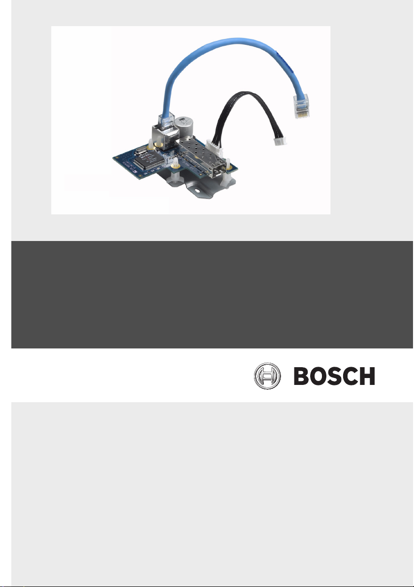
VG4 Fiber Optic Media Converter
VG4-SFPSCKT
en Installation Guide
Page 2

Page 3

Fiber Optic Media Converter Table of Contents | en iii
Table of Contents
1 Important Safety Instructions 1
1.1 Customer Support and Service 3
2 Installing the Fiber Optic Module 5
2.1 Description 5
2.2 Using an SFP Module 6
2.3 Parts Included 7
2.4 Installation Instructions 8
3 Troubleshooting 13
Bosch Security Systems, Inc. Installation Guide F.01U.134.924 | 1.0 | 2009.09
Page 4

iv en | Table of Contents Fiber Optic Media Converter
F.01U.134.924 | 1.0 | 2009.09 Installation Guide Bosch Security Systems, Inc.
Page 5

Fiber Optic Media Converter Important Safety Instructions | en 1
1 Important Safety Instructions
Read, follow, and retain all of the following safety instructions.
Heed all warnings on the unit and in the operating instructions
before operation.
1. Clean only with a dry cloth. Do not use liquid cleaners or
aerosol cleaners.
2. Do not install unit near any heat sources such as radiators,
heaters, stoves, or other equipment (including amplifiers)
that produce heat.
3. Do not block any ventilation openings.
4. Do not use the unit near water or expose to rain or
moisture. Never spill liquid of any kind on the unit.
5. Unplug the unit during lightning storms or when unused for
long periods.
6. Adjust only those controls specified in the operating
instructions.
7. Do not overload outlets and extension cords, as this can
cause fire or electrical shock.
8. Protect the plug and power cord from foot traffic or
pinching, at electrical outlets, and at its exit from the unit.
9. Operate the unit only from the type of power source
indicated on the label.
10. Unless qualified, do not attempt to service a damaged unit
yourself. Refer all servicing to qualified service personnel.
11. Use only replacement parts specified by the manufacturer.
12. Install in accordance with the manufacturer's instructions
in accordance with applicable local codes.
Use only attachments/accessories specified by the
manufacturer. Equipment change or modification could
void the user's guarantee or authorization agreement.
Bosch Security Systems, Inc. Installation Guide F.01U.134.924 | 1.0 | 2009.09
Page 6
2 en | Important Safety Instructions Fiber Optic Media Converter
!
!
WARNING!
High risk: This symbol indicates an imminently hazardous
situation such as “Dangerous Voltage” inside the product.
If not avoided, this will result in an electrical shock, serious
bodily injury, or death.
CAUTION!
Medium risk: Indicates a potentially hazardous situation.
If not avoided, this could result in minor or moderate bodily
injury.
CAUTION!
Low risk: Indicates a potentially hazardous situation.
if not avoided, this could result in property damage or risk of
damage to the unit.
You can view and print the full version of this Installation
Manual with Adobe Acrobat Reader. This user guide is the
intellectual property of Bosch Security Systems; protected by
copyright.
F.01U.134.924 | 1.0 | 2009.09 Installation Guide Bosch Security Systems, Inc.
Page 7

Fiber Optic Media Converter Important Safety Instructions | en 3
1.1 Customer Support and Service
If this unit needs service, contact the nearest Bosch Security
Systems Service Center for authorization to return and shipping
instructions.
Service Centers
USA
Repair Center
Telephone: 800-566-2283
Fax: 800-366-1329
E-mail: repair@us.bosch.com
Customer Service
Telephone: 888-289-0096
Fax: 585-223-9180
E-mail: security.sales@us.bosch.com
Technical Support
Telephone: 800-326-1450
Fax: 585-223-3508 or 717-735-6560
E-mail: technical.support@us.bosch.com
Canada
Telephone: 514-738-2434
Fax: 514-738-8480
Europe, Middle East, Africa Region
Repair Center
Telephone: 31 (0) 76-5721500
Fax: 31 (0) 76-5721413
E-mail: RMADesk.STService@nl.bosch.com
Asia Region
Repair Center
Telephone: 65 63522776
Fax: 65 63521776
E-mail: rmahelpdesk@sg.bosch.com
Customer Service
Telephone: 86 (0) 756 7633117 or
86 (0) 756 7633121
Fax: 86 (0) 756 7631710
E-mail: customer.service@cn.bosch.com
Bosch Security Systems, Inc. Installation Guide F.01U.134.924 | 1.0 | 2009.09
Page 8

4 en | Important Safety Instructions Fiber Optic Media Converter
Warranty and more information
For additional information and warranty queries, please contact
your Bosch Security Systems representative or visit our website
at www.boschsecurity.com.
F.01U.134.924 | 1.0 | 2009.09 Installation Guide Bosch Security Systems, Inc.
Page 9

Fiber Optic Media Converter Installing the Fiber Optic Module | en 5
i
2 Installing the Fiber Optic Module
This guide provides instructions for installing the Bosch VG4SFPSCKT Fiber Optic module into a VG4-A-PA1, VG4-A-PA2,
VG4-A-PSU1 or a VG4-A-PSU2 AutoDome power supply box.
2.1 Description
The VG4-SFPSCKT is a unique media converter module for use
with VG4 series AutoDomes incorporating the Ethernet (TCP/
IP) Communications Module. This media converter module is
designed to accept any of the 10/100 Mbps Small Form-factor
Pluggable (SFP) modules described below.
The media converter module along with the SFP module is user
installed directly into the AutoDome's power supply box to
provide an integrated fiber optic solution.
The Fiber Optic module accepts the following SFP modules:
Sub-module Fiber Type Optical Interface
SFP-2 MMF Duplex LC
SFP-3 SMF Duplex LC
SFP-23 SMF Single SC
SFP-24 SMF Single SC
SFP-25 MMF Single SC
SFP-26 MMF Single SC
NOTICE! The SFP module is not included with the VG4SFPSCKT kit, it must be purchased separately.
Bosch Security Systems, Inc. Installation Guide F.01U.134.924 | 1.0 | 2009.09
Page 10

6 en | Installing the Fiber Optic Module Fiber Optic Media Converter
2.2 Using an SFP Module
The SFP-23/SFP-24 modules and the SFP-25/SFP-26 modules
are counterparts; if you use one in the VG4-SFPSCKT module
then you must use the other in the CNFE2MC head-end unit. For
example, SFP-25 is used in the VG4-SFPSCKT module installed
into a VG4 power supply. You must use the SFP-26 module in
the CNFE2MC head-end unit.
The following chart lists the compatibility between the SFP
modules:
SFP Sub-module used in
VG4-SFPSCKT
SFP-2 SFP-2
SFP-3 SFP-3
SFP-23 SFP-24
SFP-24 SFP-23
SFP-25 SFP-26
SFP-26 SFP-25
Use this SFP Sub-module
in CNFE2MC
F.01U.134.924 | 1.0 | 2009.09 Installation Guide Bosch Security Systems, Inc.
Page 11

Fiber Optic Media Converter Installing the Fiber Optic Module | en 7
2.3 Parts Included
Part Description Part Number
Fiber Optic Media Converter Module F.01U.136.512
Metal adaptor base plate F.01U.072.866
Power harness (black) F.01U.026.085
Four (4) Plastic standoff pins F.01U.073.233
Ethernet patch cable (blue) with
RJ45 connectors
One (1) M2.5 Phillips pan screw F.01U.009.951
Bosch Security Systems, Inc. Installation Guide F.01U.134.924 | 1.0 | 2009.09
F.01U.032.132
Page 12

8 en | Installing the Fiber Optic Module Fiber Optic Media Converter
2.4 Installation Instructions
Use the following instructions to install the VG4-SFPSCKT Fiber
Optic module inside a VG4 Power Supply Box.
1. Unpack the fiber optic module kit, and remove the parts
from the bag.
2. Turn off the power to the VG4 power supply box and
remove the cover.
3. Remove the 6-pin connector from the P106 connector
inside the power supply box, if present.
Figure 2.1 P106 connector with 100 Ohm resistor
F.01U.134.924 | 1.0 | 2009.09 Installation Guide Bosch Security Systems, Inc.
Page 13

Fiber Optic Media Converter Installing the Fiber Optic Module | en 9
J103
4. Insert one plastic standoff pin into the hole on the main
power supply board, located to the left of the P107
(Heater) connector.
Figure 2.2 Insert standoff pin into power supply board
5. Connect the supplied power harness (black) to the J103
socket on the power supply board, located below the
Heater connector.
Figure 2.3 J103 socket location
Bosch Security Systems, Inc. Installation Guide F.01U.134.924 | 1.0 | 2009.09
Page 14

10 en | Installing the Fiber Optic Module Fiber Optic Media Converter
6. Insert three standoff pins into the metal base plate as
shown below.
Figure 2.4 Placement of standoff pins in base plate
7. Align the upper right hole in the base plate to the standoff
pin attached to the power supply box and press the base
plate onto the pin. Secure the base plate with the supplied
screw in the lower left hole of the P105 connector.
Figure 2.5 Attach base place to power supply box
F.01U.134.924 | 1.0 | 2009.09 Installation Guide Bosch Security Systems, Inc.
Page 15

Fiber Optic Media Converter Installing the Fiber Optic Module | en 11
8. Insert the SFP module into the VG4-SFPSCKT module:
Note: The SFP module is static sensitive. Use static
handling procedures when installing or removing the
module.
a. Ensure that the bale-clasp on the SFP module is up.
b. Line up the SFP module with the port on the VG4-
SFPSCKT module and slide it into the port until you
hear the catches engage.
9. Remove the rubber plug from the SFP module.
10. Align the anchor holes on the fiber optic module to the
standoff pins on the base plate and press the module onto
the standoff pins until secure.
Figure 2.6 Attach Fiber Optic board to base plate
11. Attach the supplied power harness (black) to its connector
on the fiber optic module.
Bosch Security Systems, Inc. Installation Guide F.01U.134.924 | 1.0 | 2009.09
Page 16

12 en | Installing the Fiber Optic Module Fiber Optic Media Converter
12. Connect the RJ45 Ethernet patch cable (blue) to its socket
on the fiber optic module. Then attach the other end to the
female mating connector in the AutoDome pendant arm.
Note: If installing a Pipe or Roof mounted AutoDome, you
will need to provide the appropriate length Ethernet cable
with RJ45 connectors to reach between the AutoDome and
the power supply box.
13. Route the appropriate fiber optic cable through the
conduit hole on the power supply box.
14. Plug the fiber optic cable (LC or SC connector) into the
SFP module inside the power supply unit.
15. Close and secure the power supply box when finished.
16. Restore the power to the power supply box.
F.01U.134.924 | 1.0 | 2009.09 Installation Guide Bosch Security Systems, Inc.
Page 17

Fiber Optic Media Converter Troubleshooting | en 13
3 Troubleshooting
Issue Symptom Resolution
No data present No Power Check power to VG4-SFPSCKT:
– If Green LED is present, then
Check power to CNFE2MC:
– If Power LED is Green, then
check data link
Invalid Fiber Link Check fiber connection to VG4-
SFPSCKT:
– If Red LED is present, then the
fiber link is missing. If the LED is
Flashing Red, then
Check the fiber connection to the
CNFE2MC:
– If the Link/Act LED is not lit,
then the fiber link is missing.
Bosch Security Systems, Inc. Troubleshooting F.01U.134.924 | 1.0 | 2009.09
Page 18

14 en | Troubleshooting Fiber Optic Media Converter
Issue Symptom Resolution
No Video present RJ-45 Connection Check the PWR/Link on the VG4-
SFPSCKT:
– If the LED is slowly Flashing Red,
then
Check all video connections from the
VG4 AutoDome.
– If the LED is rapidly Flashing
Red, then
Check the RJ-45 connector on the
VG4-SFPSCKT:
– If the right LED (Green) is not lit,
then no data is present at this
RJ-45 connection.
– If no LED lit on the RJ-45
connector, then there is a fault
with this connector, the RJ-45
cable, or the cable is not
connected to the CNFE2MC.
Check the RJ-45 connector on the
CNFE2MC:
– If the right LED (Green) is not lit,
then no data is present at this
RJ-45 connection.
– If no LED lit on the RJ-45
connector, then there is a fault
with this connector, the RJ-45
cable, or the cable is not
connected to the VG4-SFPSCKT.
F.01U.134.924 | 1.0 | 2009.09 Installation Guide Bosch Security Systems, Inc.
Page 19

Page 20

Americas
Bosch Security Systems, Inc.
850 Greenfield Road
Lancaster, Pennsylvania 17601
USA
Telephone +1 888-289-0096
Fax +1 585-223-9180
Email:
security.sales@us.bosch.com
www.boschsecurity.us
Europe, Middle East, Africa:
Bosch Security Systems B.V.
P.O. Box 80002
5600 JB Eindhoven,
The Netherlands
Phone: + 31 40 2577 284
Fax: +31 40 2577 330
emea.securitysystems@bosch.com
www.boschsecurity.com
Asia-Pacific:
Bosch Security Systems Pte Ltd
38C Jalan Pemimpin
Singapore 577180
Phone: +65 6319 3450
Fax: +65 6319 3499
apr.securitysystems@bosch.com
www.boschsecurity.com
© Bosch Security Systems, Inc. 2009; F.01U.134.924 | 1.0 | 2009.09;
Data subject to change without notice.
 Loading...