

Bosch VDC445V0320S, FlexiDomeXT+, VDC-455Vxx-10, VDC-455Vxx-20, VDC-355Vxx-10 Installation Instructions Manual
...
FlexiDome
XT+
Installation Instructions
Vandal resistant surveillance dome
EN
Manuale d’installation
Caméra anti-vandalisme
FR
Installationshandbuch
Schlagfeste Kuppelkamera
DE
Installatiehandleiding
Vandalismebestendige
bewakingskoepel
NL
Manual de instalación
Burbuja de vigilancia
antivandálica
ES
Manuale di installazione
Cupola antivandalismo
per sorveglianza
IT
Manual de Instalação
Dome de vigilância
anti-vandalismo
PT
安装手册
防暴型监控球型摄像机
ZH

FlexiDome
XT+
| User Manual
Bosch Security Systems | 2008-08 | V1.1
EN | 3
SAFETY PRECAUTIONS
Important Safeguards
1. Read these instructions.
2. Keep these instructions.
3. Comply with all warnings.
4. Follow all instructions.
5. Do not use this equipment near water.
6. Clean only with dry cloth.
7. Do not block any ventilation openings. Install in accordance with the
manufacturer’s instructions.
8. Do not install near any heat sources such as radiators, heat registers,
stoves, or other equipment (including amplifiers) that produce heat.
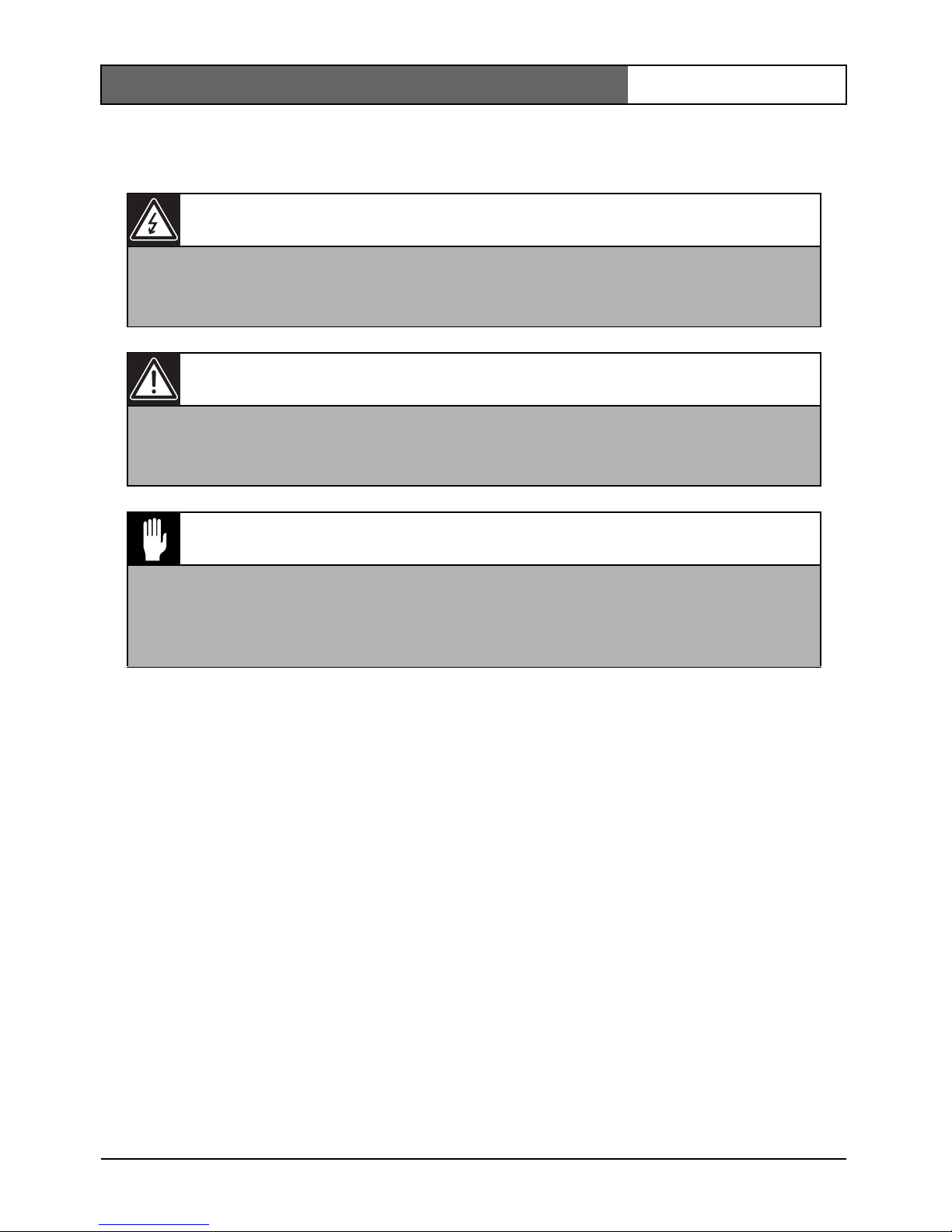
Danger
The lightning flash with arrowhead symbol, within an equilateral triangle,
is intended to alert the user to the presence of uninsulated “dangerous
voltage” within the product's enclosure that may be of sufficient
magnitude to constitute a risk to persons.
Warning
The exclamation mark within an equilateral triangle is intended to alert
the user to the presence of important operating and maintenance
(servicing) instructions in the literature accompanying the appliance.
Caution
To reduce the risk of electric shock, do not remove cover (or back). No
user-serviceable parts inside. Refer servicing to qualified service
personnel.
FlexiDome
XT+
| User Manual
Bosch Security Systems | 2008-08 | V1.1
EN | 4
9. Do not defeat the safety purpose of the polarized or grounding-type
plug. A polarized plug has two blades with one wider than the other.
A grounding type plug has two blades and a third grounding prong.
Both the wide blade and the third prong are provided for your safety.
If the supplied plug does not fit into your outlet, consult an electrician
for advice.
10. Protect the power cord from being walked on or pinched particularly at
plugs, convenience receptacles, and the point where they exit from the
equipment.
11. Only use attachments/accessories specified by the manufacturer.
12. Unplug this equipment during lightning storms or when unused for
long periods of time.
13. Refer all servicing to qualified service personnel. Servicing is required
when the equipment has been damaged in any way, such as when
power supply cord or plug is damaged, liquid has been spilled or
objects have fallen into the equipment, the equipment does not operate
normally, or has been dropped.
14. An all-pole mains switch with a contact separation of at least 3mm in
each pole shall be incorporated in the electrical installation of the
building.
Caution
The Low Voltage power supply unit must comply with EN/UL 60950. The
power supply must be a SELV-LPS unit or a SELV - Class 2 unit (Safety
Extra Low Voltage - Limited Power Source).

FlexiDome
XT+
| User Manual
Bosch Security Systems | 2008-08 | V1.1
EN | 5
FCC Information
This equipment has been tested and found to comply with the limits for a
Class B digital device, pursuant to part 15 of the FCC Rules. These limits
are designed to provide reasonable protection against harmful interference
in a residential installation. This equipment generates, uses and can radiate
radio frequency energy and, if not installed and used in accordance with
the instructions, may cause harmful interference to radio communications.
However, there is no guarantee that interference will not occur in a
particular installation. If this equipment does cause harmful interference to
radio or television reception, which can be determined by turning the
equipment off and on, the user is encouraged to try to correct the
interference by one or more of the following measures:
• Reorient or relocate the receiving antenna.
• Increase the separation between the equipment and receiver.
• Connect the equipment into an outlet on a circuit different from that
to which the receiver is connected.
• Consult the dealer or an experienced radio/ TV technician for help.
Note
Any change or modification of the equipment not expressly approved by
Bosch could void the user's authority to operate the equipment. For
additional information or to speak to a representative, please contact the
Bosch Security Systems location nearest to you or visit our web site at
www.boschsecuritysystems.com

FlexiDome
XT+
| Installation Manual
Bosch Security Systems | 2008-08 | V1.1
EN | 6
Introduction
The FlexiDome
XT+
camera is a small, discreet, high-security surveillance
dome containing a high-performance 1/3-inch CCD camera with integral
varifocal lens. The integrated unit is mounted to an electrical box or to a
wall or ceiling. The sturdy construction and high impact resistant
polycarbon dome protect the camera module from damage.
The camera incorporates advanced digital signal processing for
outstanding picture performance under all lighting conditions. The
FlexiDome
XT+
camera is easy to install and ready to use, and offers the best
solution for demanding scene conditions.
Features include:
• Impact-resistant dome
• Tamper-resistant housing
•NightSense™
• Lens focus aid
• Bilinx™ bi-directional coaxial communications
The FlexiDome
XT+
camera is available in color and monochrome versions.

FlexiDome
XT+
| Installation Manual
Bosch Security Systems | 2008-08 | V1.1
EN | 7
Unpacking
Unpack carefully and handle the equipment with care. The packaging
contains:
• Integrated FlexiDome camera
• Mounting hardware kit
• Special screwdriver for tamper resistant screw
• Lens adjustment cap
• Installation manual
Note
If equipment appears to have been damaged during shipment, repack it in
the original packaging and notify the shipping agent or supplier.
FlexiDome
XT+
| Installation Manual
Bosch Security Systems | 2008-08 | V1.1
EN | 8
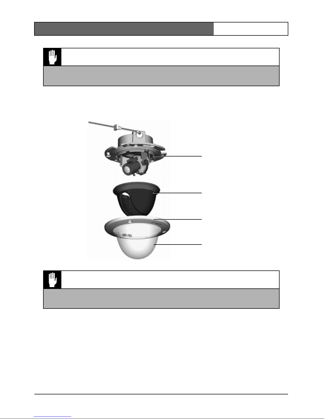
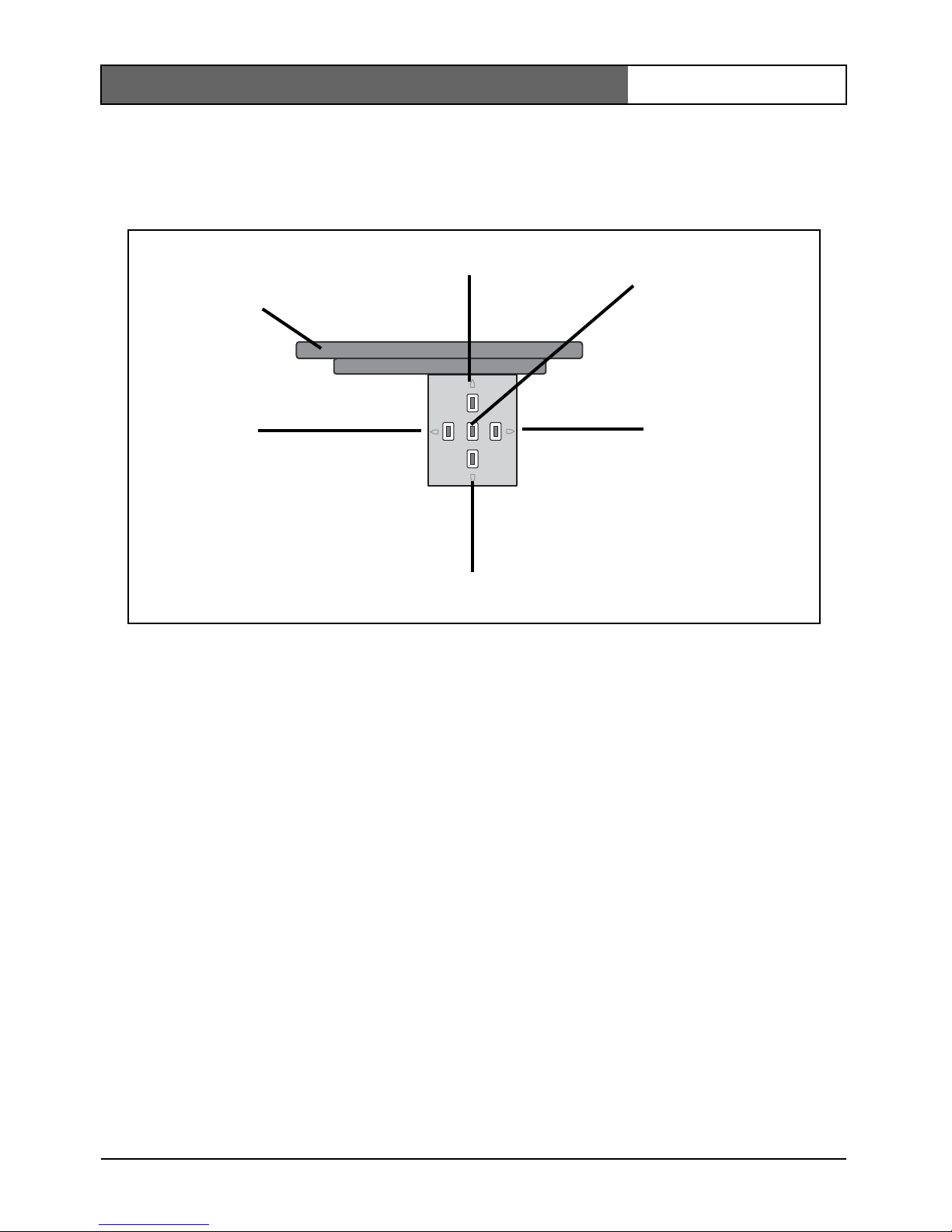
Disassembly
The camera/housing unit consists of the following parts:
To disasemble the unit proceed as follows:
• Using the special screwdriver, loosen the three tamper resistant screws
in the trim ring (the screws remain in place).
• Remove the trim ring with dome by pulling it off of the base.
• Remove the inner liner by pulling it off of the base.
Caution
Installation should only be performed by qualified service personnel in
accordance with the National Electrical Code or applicable local codes.
Caution
The camera module is a sensitive device and must be handled carefully.
Do not drop when disassembling the unit.
Camera module and
mounting base
Inner liner
Trim ring
Dome
FlexiDome
XT+
| Installation Manual
Bosch Security Systems | 2008-08 | V1.1
EN | 9
Mounting the unit
The unit may be mounted in several different ways depending on the type
of surface, whether an electrical box is used and whether the connection is
via the rear or the side (surface mounted).
If the unit is surface mounted, use the separately available raised mounting
base (VDA-455SMB) and mount the unit onto this base.
Tips
• Refer to the dimensions drawing to find the exact position of the screw
holes and the entry hole for the wires.
• Partially screw in two screws for the keyholes and use them to
temporarily hang the camera while the connections are made.
The following figures show the different ways of mounting the unit.
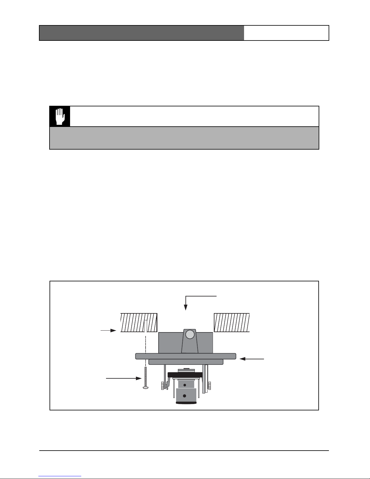
Figure 1 Rear connection - hollow surface
Caution
Installation should only be performed by qualified service personnel in
accordance with the National Electrical Code or applicable local codes.
Wires
Strong surface
(four pre-drilled
8mm holes)
Three screws
(supplied)
Mounting
base
FlexiDome
XT+
| Installation Manual
Bosch Security Systems | 2008-08 | V1.1
EN | 10
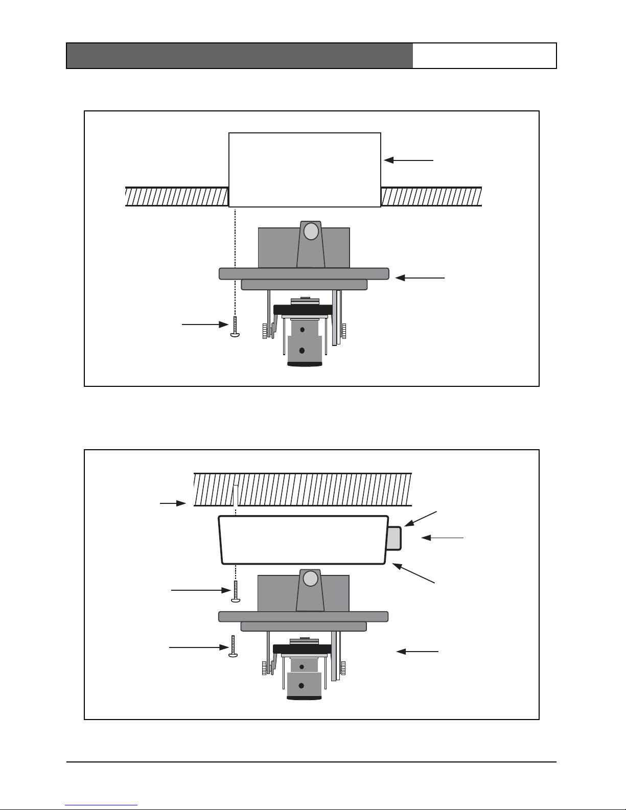
Figure 2 Connection to an electrical box (4S)
Figure 3 Surface mounting - side connection
S4 Electrical
box
Two screws
(not supplied)
Mounting
base
Wires
Three screws
(M5, supplied)
Surface
mounting box
(VDA-455SMB)
Conduit
Three screws
(supplied with
camera)
Camera unit
and base
Solid surface
(three pre-drilled
8mm holes)
FlexiDome
XT+
| Installation Manual
Bosch Security Systems | 2008-08 | V1.1
EN | 11
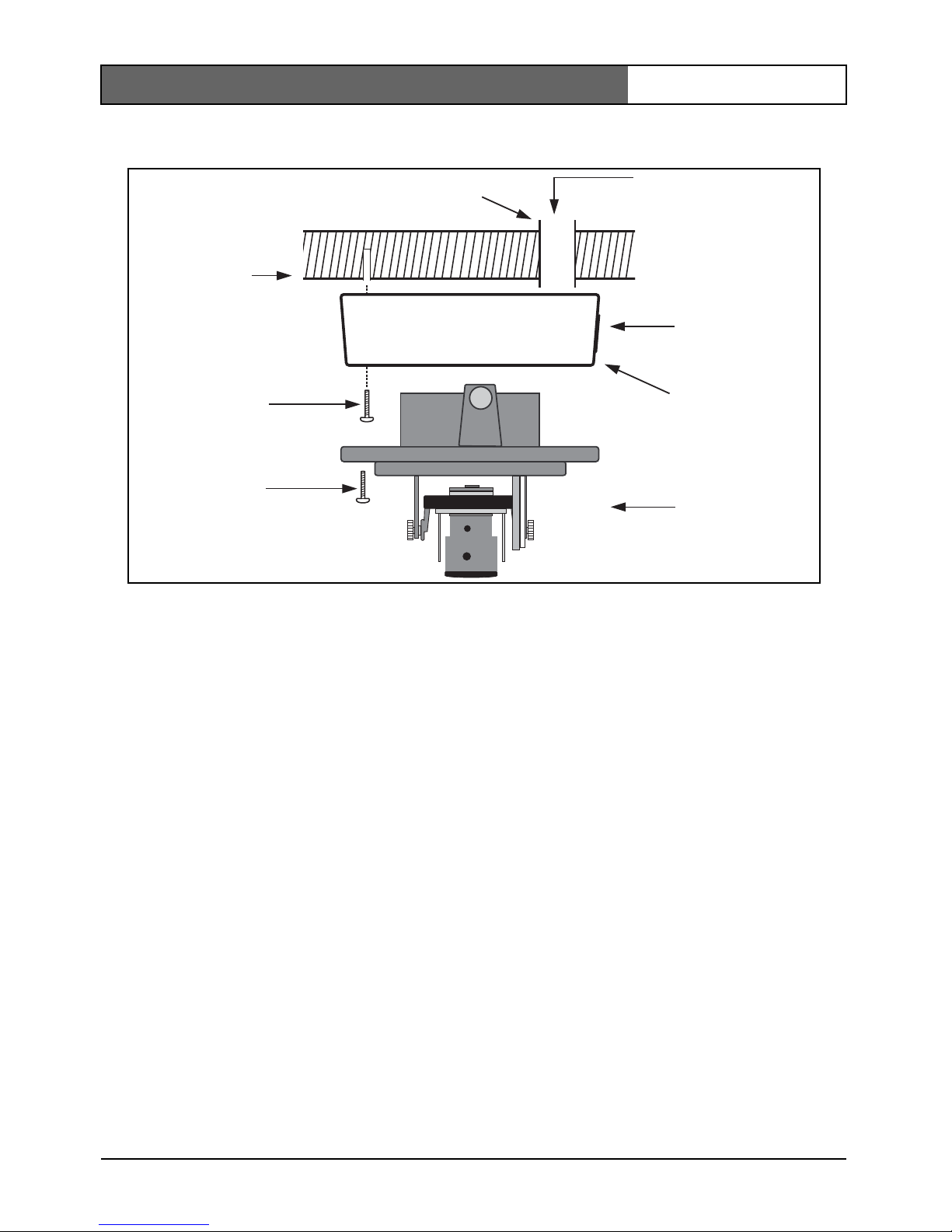
Figure 4 Surface mounting - rear connection
Surface mounting
When using the raised mounting box:
• With a side connection, remove the cap covering the side entrance.
With a rear connection, leave the cap in place.
• Attach the conduit to the mounting box.
• Release the two clips at the bottom of the watertight connection
compartment to remove it from the mounting box.
• Open the cover of the watertight compartment in the mounting box by
releasing the 5 clips.
• Run the power and video wires through separate rubber grommets into
the watertight compartment.
• Run the cable from the camera into the watertight compartment
through the supplied grommet.
• Make the connection inside the watertight compartment and clip on
the cover to seal it.
Note
In order to ensure a watertight cable entry, use round cables of between 5
and 6 mm (0.2 - 0.24 inches) for power and video connection. Use some
silicon spray on the cable to help slide the grommets onto it.
Cap
Three screws
(M5, supplied)
Surface
mounting box
(VDA-455SMB)
Conduit
Three screws
(supplied with
camera)
Camera unit
and base
Solid surface
(three pre-drilled
8mm holes)
Wires
FlexiDome
XT+
| Installation Manual
Bosch Security Systems | 2008-08 | V1.1
EN | 12
Connection in outdoor applications
Safety precautions:
Coax grounding: If an outside cable system is connected to the unit,
ensure that the system is grounded.
U.S.A. models only - Section 810 of the National Electrical Code, ANSI/
NFPA No.70, provides information regarding proper grounding of the
mount and supporting structure, grounding of the coax to a discharge unit,
size of grounding conductors, location of discharge unit, connection to
ground electrodes, and requirements for the grounding electrode.
Power lines:
An outdoor system should not be located in the vicinity of
overhead power lines, electrical lights, or power circuits, or where it may
contact such power lines or circuits. When installing an outdoor system,
extreme care should be taken to keep from touching power lines or circuits,
as this contact may be fatal. U.S.A. models only - refer to the National
Electrical Code Article 820 regarding installation of CATV systems.
24 VAC power source:
This unit is intended to operate with a limited power
source, this power source must comply with EN60950. When the unit is
intended to operate at 24 VAC, normal input voltage is between 12 VAC and
28 VAC. Voltage applied to the unit's power input should not exceed 28 VAC.
User supplied wiring, from 24 VAC supply to unit, must be in compliance
with electrical codes (Class 2 power levels). Do not ground the 24 VAC supply
at the terminals or at the unit's power supply terminals.
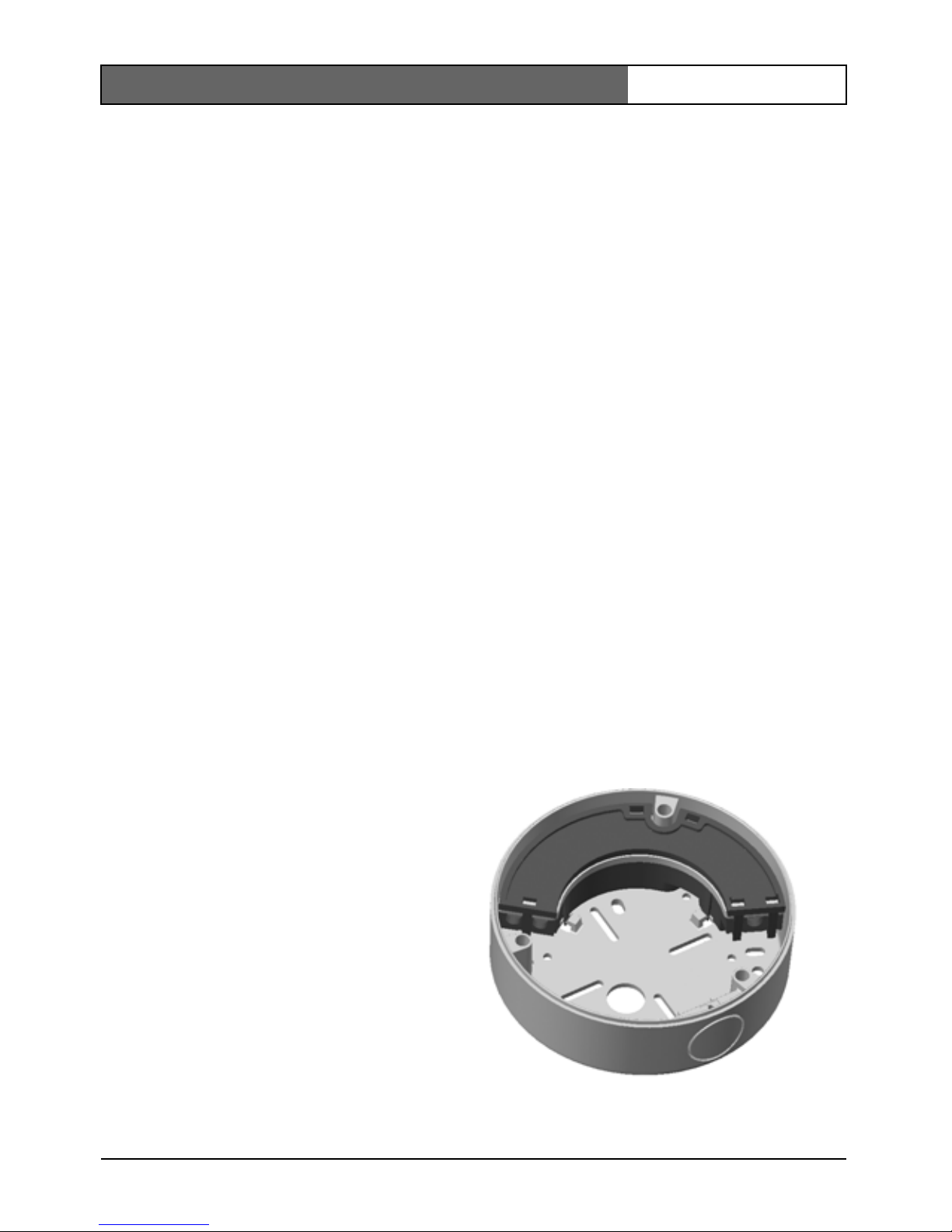
Connection: The unit has
connection terminals on flying
leads. In wet or outdoor
installations make use of the
VDA-455SMB accessory or use a
field wiring box with Nema3 or
IP55 protection level or better.
Make the connections inside the
water tight compartment. After
connections are made ensure that
the watertight compartment is
tightly closed and cables and
conduits are properly sealed to
prevent ingress of water.
VDA-455SMB
FlexiDome
XT+
| Installation Manual
Bosch Security Systems | 2008-08 | V1.1
EN | 13
Connection and set-up
Power and video connections
The wiring harness has a BNC connector to accept the video coax cable
(with male BNC connector) and two stripped low voltage power wires for
connection to a power connector. (A UTP adapter is available as an
accessory to allow a UTP video cable to be connected to the BNC
connector.)
The easiest way to connect the low voltage power lines and the video
connection is as follows:
• Bring the building connections through the surface wire hole so that
they hang clear.
• Partially insert two screws into the pre-drilled holes (or adapter plate).
• Using the keyholes, hang the mounting base on one screw temporarily
and tilt the base slightly to gain access to the cable connections.
• Connect the BNC connector of the camera module to the video coax
cable.
• Connect the stripped power wires to the power supply connector.
Note
For a DC supply the polarity is not important. For an AC supply try to
maintain a consistent wiring polarity in multiple camera systems to help
avoid rolling when switching.
• In damp environments ensure that the connections are sealed.
(The surface mounting box has a sealed compartment for this.)
• Push the connections back through the surface wire hole.
• Secure the mounting base to the surface with three screws.
Caution
Before proceeding, be sure to disconnect the power from the cable to be
installed into the unit. Be sure that the unit is of the proper voltage type
for the line power being used.
FlexiDome
XT+
| Installation Manual
Bosch Security Systems | 2008-08 | V1.1
EN | 14
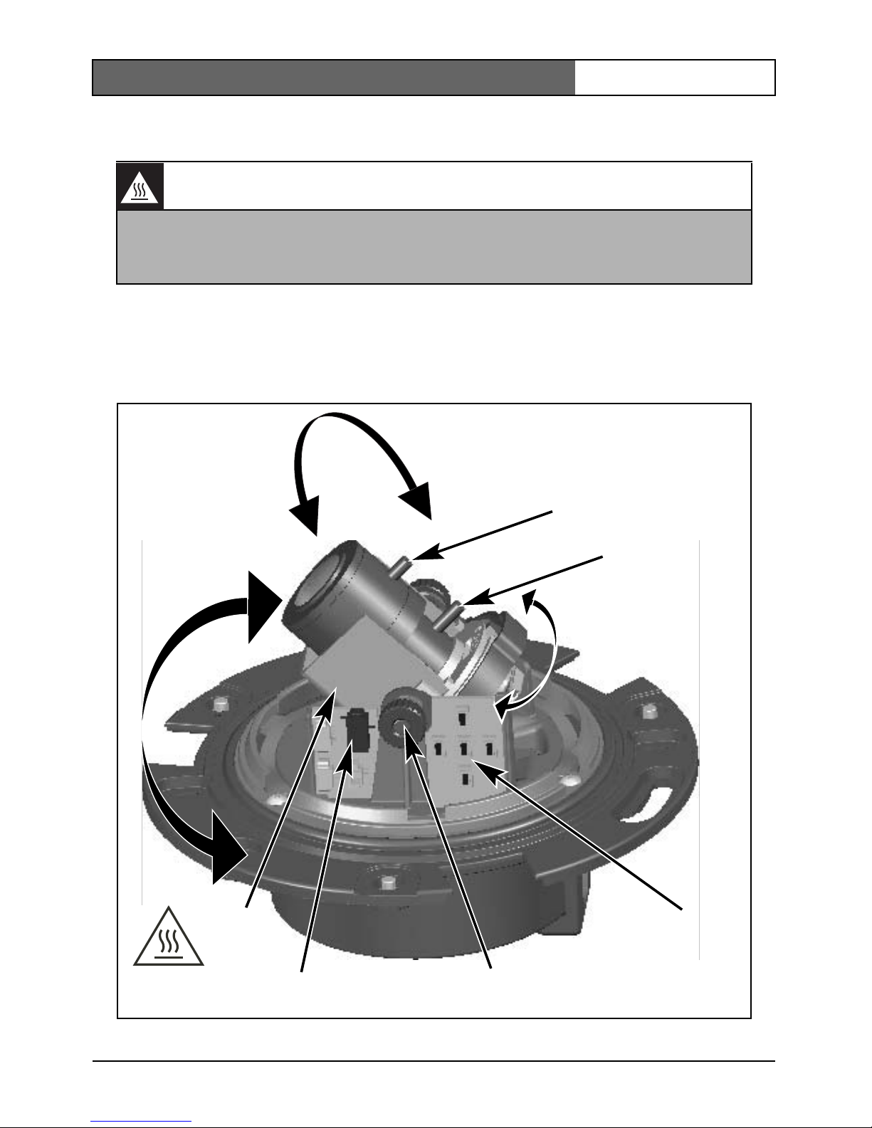
Setting up the camera
You can connect a monitor to the miniature 2.5mm jack socket on the
printed circuit board to help set up the camera. This socket provides a
composite video signal (with sync). An optional cable (code number
S1460) is available for making this connection.
Warning: Hot Surface
The Heater will be HOT when in operation - DO NOT TOUCH. Always
switch the heater OFF, when working on the camera.
Refer to the installer menu (see Menu Structure) for instructions.
Thumbwheels
Monitor jack
Navigation
switches
Focus
Focal length
Heater
FlexiDome
XT+
| Installation Manual
Bosch Security Systems | 2008-08 | V1.1
EN | 15
Camera positioning
The physical default position of the camera is that the top of the image
corresponds to the indication TOP.
The camera module position can be adjusted along three axes. When
adjusting the camera position ensure that the picture display on the
monitor is level. Set the camera to the desired position by performing the
following steps:
• For horizontal adjustment (pan), rotate the camera module in the base.
Do not rotate more than 360°.
• For vertical adjustment (tilt), loosen thumbscrews, position camera,
then gently tighten thumbscrews to secure camera.
• To obtain a horizontal horizon (for tilted ceilings or sidewall
mounting), rotate the base of the lens as necessary to align the picture
shown on the monitor. Do not rotate more than 340°.
Focal length and focus
Before adjusting, place the adjustment cap on the lens to ensure that the
image sharpnes is the same as when the dome is in place.
• To set the field of view of the varifocal lens, loosen the focal length
screw and turn the mechanism until the required view is displayed on
the monitor. (Image goes out of focus.)
• Focus the image on the monitor by loosening the focus screw and
turning the mechanism until the image is in focus.
• Readjust the focal length if necessary.
• Repeat these two adjustments until the desired view is in focus.
• Tighten both screws.
Remove the adjustment cap from the lens and the monitoring jack.
Caution
The CCD image sensors are highly sensitive and require special care for
proper performance and extended lifetime. Do not expose them to direct
sunlight or bright spotlights in operating and non-operating conditions.
Avoid bright lights in the field of view of the camera.

FlexiDome
XT+
| Installation Manual
Bosch Security Systems | 2008-08 | V1.1
EN | 16
Heater
When using the camera at low temperatures, select the heater setting to
"Auto" in the Installer Menu (see Menu Structure).
Closing the unit
When the camera position is set and all adjustments have been made, close
the unit.
• Place the inner liner in position aligning its fin with the bracket on the
base.
• Place the dome onto the base and rotate until it clips into place. (If
necessary clean its surface with a soft cloth.)
• Place the sealing ring and the trim ring over the dome.
• Align the tamper resistant screws in the trim ring with a thread holes in
the mounting base.
• Use the special screwdriver supplied to tighten the three tamper
resistant screws.

FlexiDome
XT+
| Installation Manual
Bosch Security Systems | 2008-08 | V1.1
EN | 17
Advanced Set-up
The FlexiDome
XT+
normally provides an optimal picture without the need
for further adjustments. However, advanced set-up options are available for
getting the best results from the camera under special circumstances. There
are two menus; a Main menu and an Installer menu.
The Main menu allows you to select and set-up the picture enhancement
functions for each mode. If you are not happy with your changes, you can
always recall the default values for the mode.
The camera also has an Installer menu in which the installation settings
can be set.
The Main and Installer menus have functions that can be selected directly
or submenus for more detailed set-up.
Accessing and navigating menus
Five keys are used for navigating through the various menus. To access the
set-up menus, press the menu/select key (center). The main menu appears
on the OSD. Use the arrow keys for navigation.
When the Bilinx™ communications link is active, the buttons on the
camera are disabled. You can also set up Bilinx™ so that the camera
buttons remain disabled even when Bilinx™ is not actively controlling the
camera. This prevents unauthorized change of the camera settings.
FlexiDome
XT+
| Installation Manual
Bosch Security Systems | 2008-08 | V1.1
EN | 18
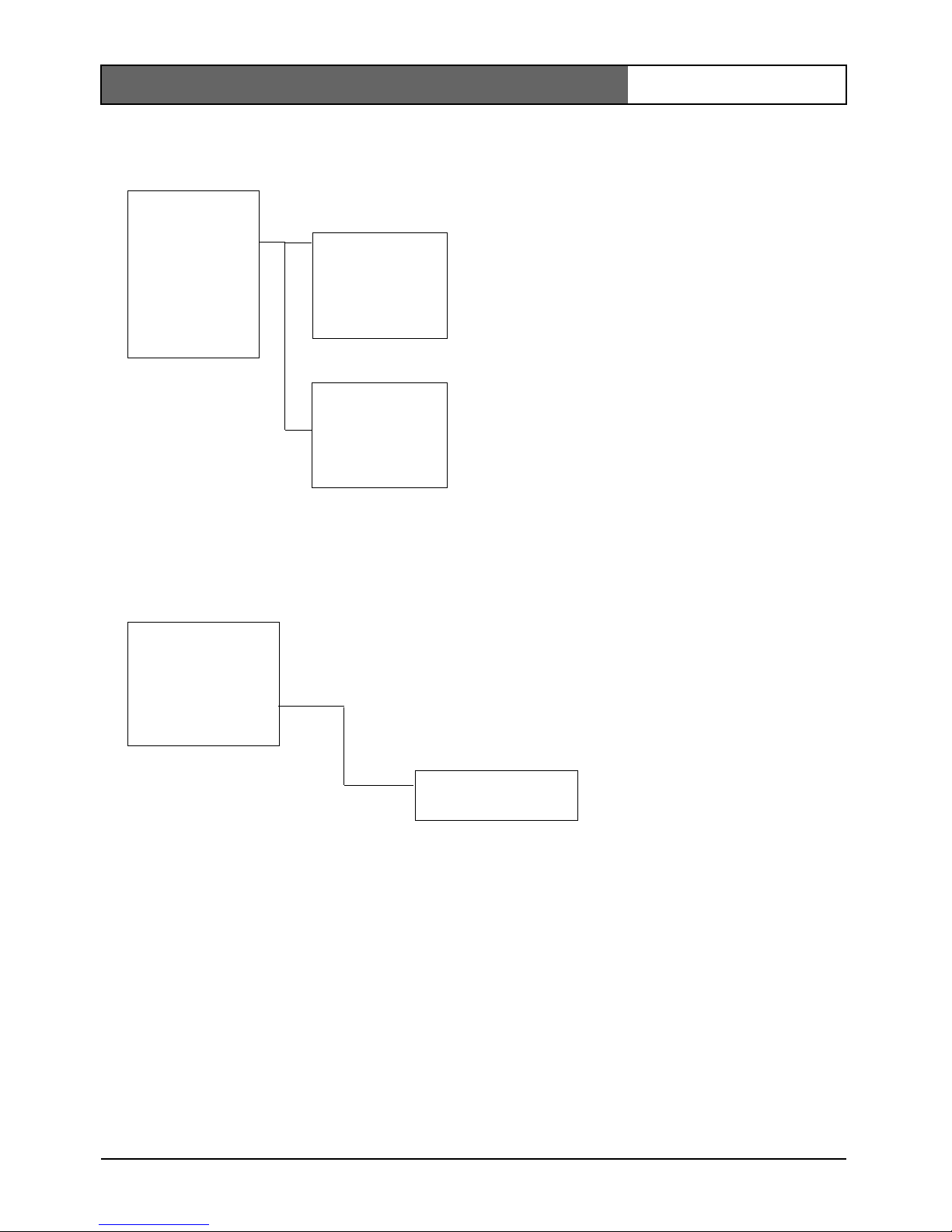
Menu Structure
* Only for the Color version of the camera.
Main menu
Level
Shut/AGC
BLC
Color
Sync
Vphase
Exit
Shut/AGC
Shutter
AGC
Auto black
NightSense*
COLOR*
White
balance
R-gain
B-gain
Installer
Set focus now
Comm
Heater
Defaults
Exit
Defaults
Restore all?
FlexiDome
XT+
| Installation Manual
Bosch Security Systems | 2008-08 | V1.1
EN | 19
Hints for menu navigation
How to use the 5 keys
• Press the menu/select key to access the menus or to move to the next
or previous menu.
• Press the menu/select key for approximately 1.5 seconds to open the
Installer menu.
• Use the up or down keys to scroll up or down through a menu.
• Use the left or right keys to move through options or to set parameters.
• When in a menu, quickly pressing the menu/select key twice restores
the selected item to its factory default.
• To close all menus at once from any menu, select the Exit item and
hold down the menu/select key until the menu display disappears.
Menu/select key
Right key
Down key
Up key
Left key
Camera
base
FlexiDome
XT+
| Installation Manual
Bosch Security Systems | 2008-08 | V1.1
EN | 20
Main menu
* Only in color version of camera. If a color camera is in monochrome
mode, all color related menu items are disabled and cannot be accessed.
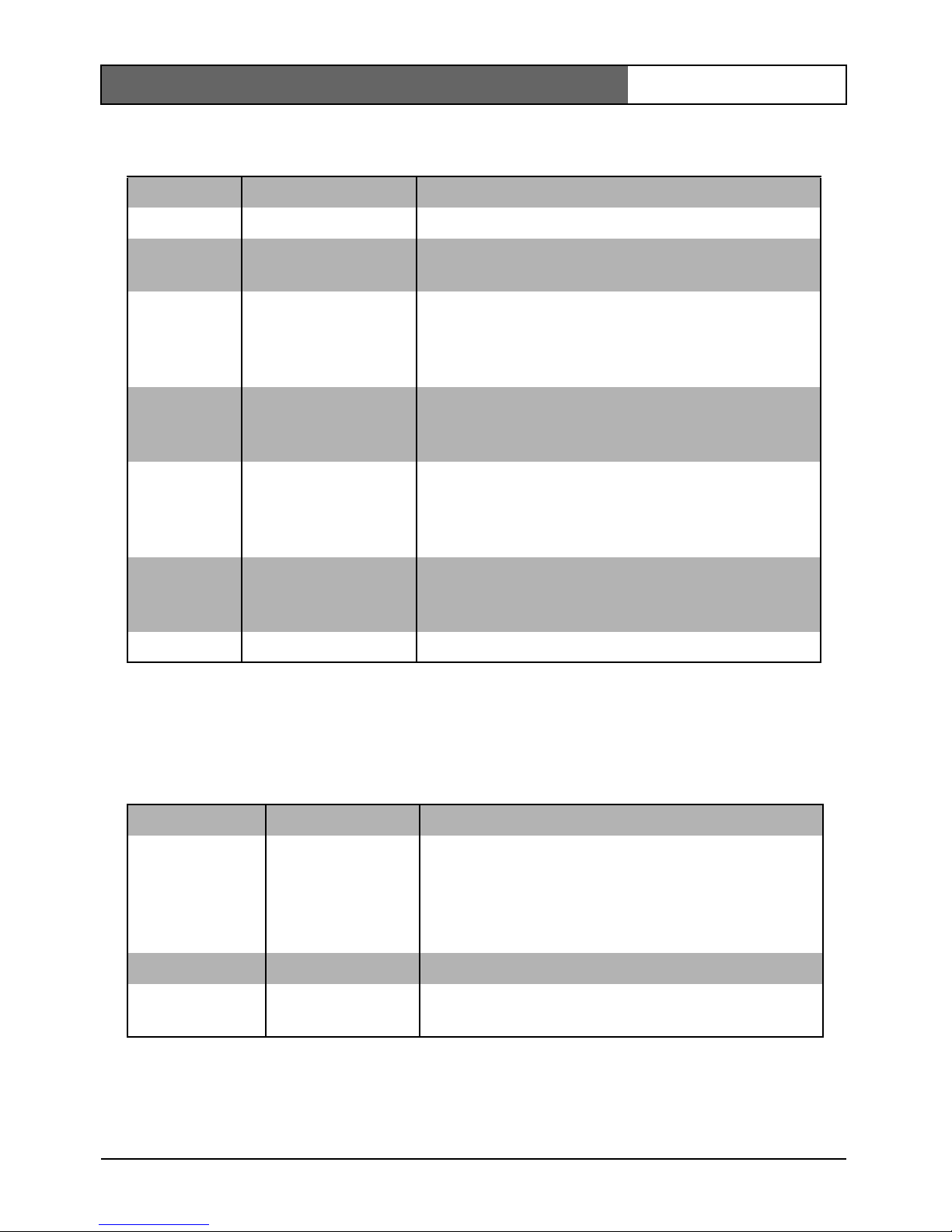
Shutter/AGC submenu
Function Selection Description
LEVEL -15 - 0 - +15 Adjusts the video output level
SHUT/AGC Select submenu Select to access the Shutter / Automatic Gain
Control menu
BLC ON, OFF When ON, the video level is optimized for the
selected area of the image. Parts outside this
area may be underexposed or overexposed
(this is normal).
COLOR* AT W
ATB HOLD
Select submenu
Select to access the color menu.
SYNC LINE LOCK
INTERNAL
Select LINE LOCK to synchronize with the
power supply frequency. Select INTERNAL for
use with internal synchronization
(automatically selected with DC supply).
VPHASE 0, 2, … 358° Adjusts the vertical phase offset (when in LINE
LOCK mode and a valid power supply
frequency is detected).
EXIT Exit the menu
Function Selection Description
SHUTTER AES, FL •AES - auto-shutter - the camera automatically
sets the optimum shutter speed
•FL - flickerless mode avoids interference from
light sources (recommended for use with
video iris or DC iris lenses only)
AGC ON/OFF Automatic gain control
AUTOBLACK ON/OFF Autoblack automatically increases the visibility
of details.
FlexiDome
XT+
| Installation Manual
Bosch Security Systems | 2008-08 | V1.1
EN | 21
* Only in color version of camera.
Note
If NightSense™ is active, some noise or spots may appear in the picture.
This is normal camera behavior.
If a color camera is in monochrome mode, all color related menu items are
disabled and cannot be accessed.
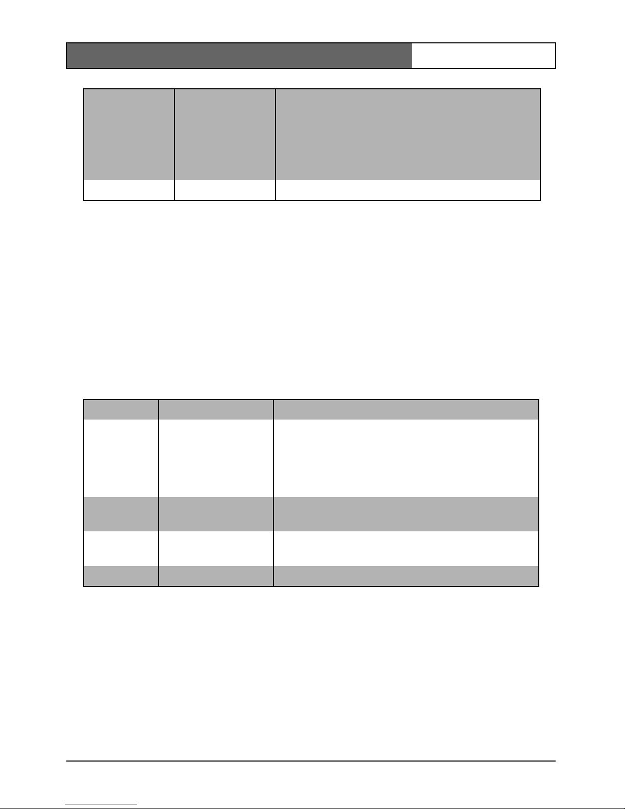
Color submenu*
* Only in color version of camera.
** It is only necessary to change the white point offset for special scene
conditions.
NIGHTSENSE* AUTO
FORCED
OFF
Nightsense™ extends the low-light
performance of the camera.
•In AUTO mode, the camera automatically
inches to monochrome in low-light conditions.
•In FORCED mode, the camera remains in highsensitivity monochrome operation.
EXIT Exit the menu
Function Selection Description
WHITE
BALANCE
AT W
AWB HOLD
•ATW: Auto tracking white balance allows the
camera to constantly adjust for optimal color
reproduction.
•AWB HOLD: Puts the ATW on hold and saves
the color settings.
RED gain** -5 - 0 - +5 Offset factory white point alignment (reducing
red introduces more cyan).
BLUE gain** -5 - 0 - +5 Offset factory white point alignment (reducing
blue introduces more yellow).
EXIT Exit the menu
FlexiDome
XT+
| Installation Manual
Bosch Security Systems | 2008-08 | V1.1
EN | 22
Installer Settings
Install menu
Adjustment procedure DC-iris Lens:
1. Unlock the focus locking screw.
2. SET BACK FOCUS NOW is highlighted in the menu.
3. Turn the focus adjustment as required.
4. Lock the focus locking screw.
5. Exit the menu selection.
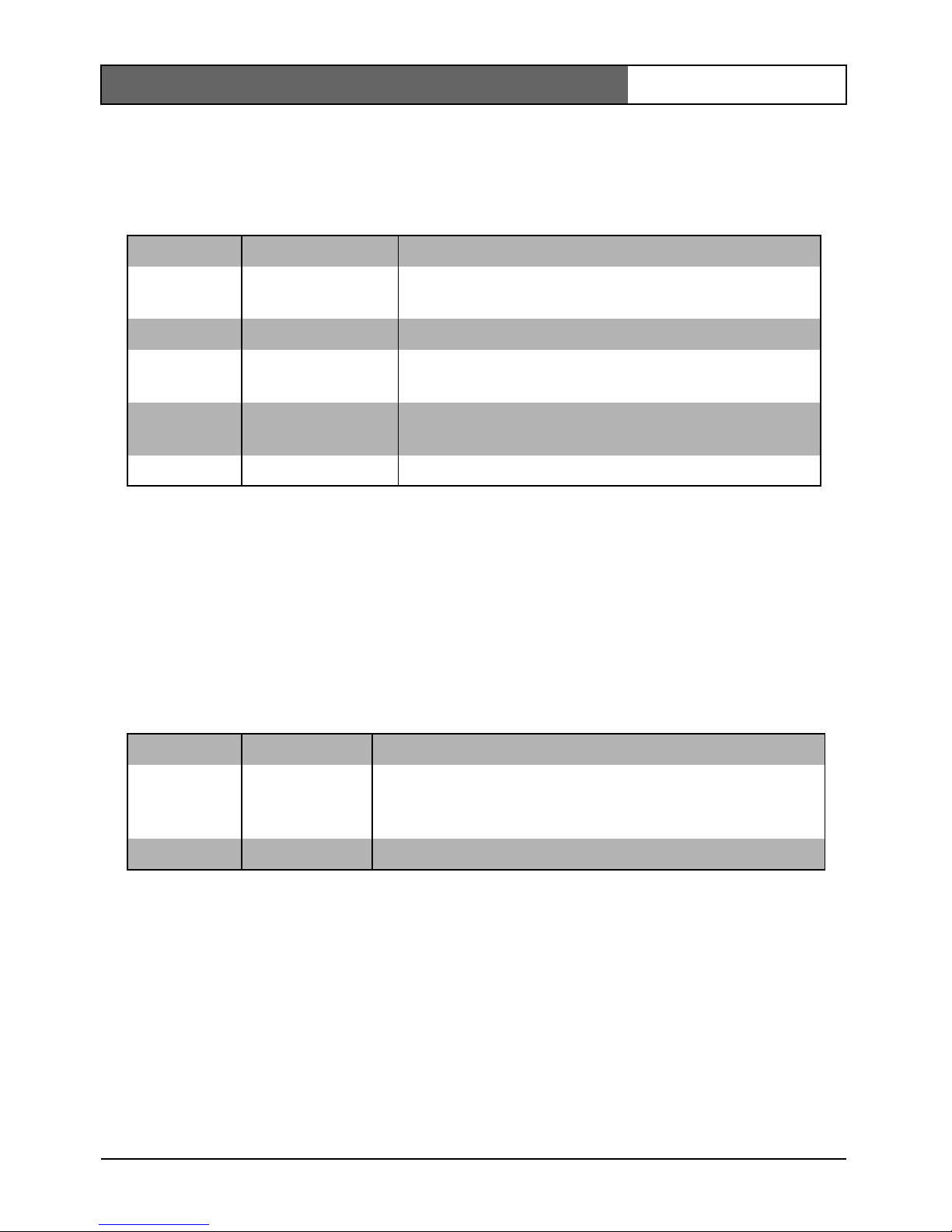
Defaults submenu
Camera control communication
This camera is equipped with a coaxial communications transceiver. In
combination with VP-CFGSFT, the camera can be adjusted from the headend side of the coaxial cable. All menus can be accessed remotely giving
full control of the camera. With this communication it is also possible to
disable the local keys on the camera. To avoid loss of communication on
an installed camera, the Communication ON/OFF selection is not
available while using remote control. This function can only be accessed
with the camera buttons.
Function Selection Description
SET FOCUS
NOW
Forces the lens to fully open the iris. Adjust the
lens focus now.
COMM ON, OFF Bilinx communication ON/OFF
HEATER AUTO, OFF Select AUTO to enable the thermostatically
controlled heater function
DEFAULTS Select submenu Return all settings for all modes to factory
defaults
EXIT Exit the menu
Function Selection Description
ALL
DEFAULTS
Select to restore the factory defaults. A confirmation
screen appears. Allow 5 seconds for the camera to
optimize the picture after a mode reset.
EXIT Exit the menu
FlexiDome
XT+
| Installation Manual
Bosch Security Systems | 2008-08 | V1.1
EN | 23
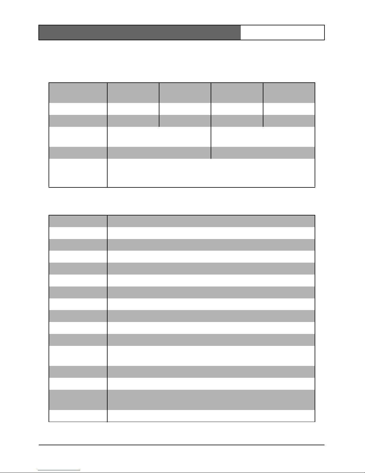
Technical specification
Type number VDC-
455Vxx-10
VDC455Vxx-20
VDC355Vxx-10
VDC-
355Vxx-20
Standard PAL NTSC CCIR EIA
Active pixels 752x582 768x492 752x582 768x492
Min illumination < 1.0 lux
< 0.2 lux
Resolution 540 TVL 570 TVL
Rated supply
voltage
24 VAC or 12 VDC
12-28 VAC (50/60 Hz)
11-36 VDC
All versions
Imager Interline CCD
SNR > 50 dB
Video output 1 Vpp, 75 Ohm
Synchronization Internal or Line Lock selectable
Shutter AES (1/60 (1/50) to 1/100000), Flickerless selectable
Auto black On, Off selectable
AGC AGC On (20 dB) or Off selectable
Contour Sharpness enhancement
BLC BLC On or Off selectable
White balance* Automatic 2500 - 9000K (with AWB hold mode)
Lens Integrated Varifocal with DC iris
Power
consumption
< 5 W
Dimensions 58 x 66 x 122 mm (HxWxL) without lens
Weight 550g without lens
Operating
temperature
-30° to 50° C (-50° with heater AUTO enabled
Controls OSD with softkey operation
FlexiDome
XT+
| Installation Manual
Bosch Security Systems | 2008-08 | V1.1
EN | 24
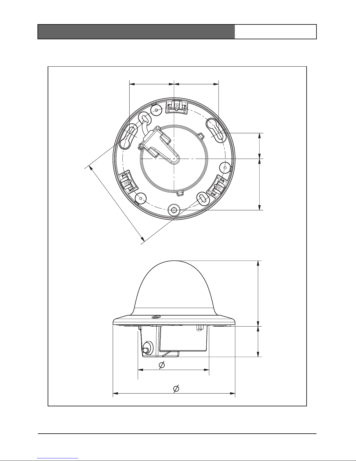
Dimensions (mm/inches)
57.6
2.27
57.6
2.27
15 8
6.22
39.5
1.56
85
3.35
33.3
1.31
66.5
2.62
121
4. 77
95
3. 7
FlexiDome
XT+
| Installation Manual
Bosch Security Systems | 2008-08 | V1.1
EN | 25
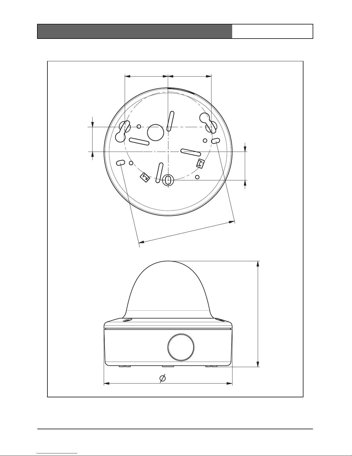
Dimensions with surface mount box (mm/inch)
53.3
2.1
53.3
2.1
30.8
1. 21
35
1. 38
130 . 5
5.14
158
6.22
121
4.77

FlexiDome
XT+
| Installation Manual
Bosch Security Systems | 2008-08 | V1.1
EN | 26
Accessories
Power transformers
• TC1334 120VAC, 60Hz - 24VAC, 30VA
• TC120PS 120VAC, 60Hz - 15VDC, 9VA
• TC220PSX-24 220-240VAC, 50/60Hz - 24VAC, 30VA
• TC220PS 220-240VAC, 50/60Hz - 15VDC, 9VA
Interface box:
• VP-CFGSFT Bilinx™ communication interface box and software

FlexiDome
XT+
| Installation Manual
Bosch Security Systems | 2008-08 | V1.1
EN | 27

FlexiDome
XT+
| Installation Manual
Bosch Security Systems | 2008-08 | V1.1
EN | 28
FlexiDome
XT+
| Manuel d’utilisation
Bosch Security Systems | 2008-08 | V 1.1
FR | 29
CONSIGNES DE SÉCURITÉ
Consignes de sécurité importantes
1. Lisez attentivement les instructions ci-après.
2. Conservez ces instructions pour référence ultérieure.
3. Conformez-vous aux différents avertissements fournis.
4. Suivez l'ensemble de ces instructions.
5. Évitez d'utiliser l'appareil à proximité d’une source d’humidité.
6. Pour nettoyer l'appareil, utilisez uniquement un chiffon sec.
7. N'obstruez en aucun cas les orifices d’aération. Installez l'appareil
conformément aux instructions du fabricant.
8. Évitez d'installer l'appareil à proximité de sources de chaleur telles
qu'un radiateur, une bouche d’air chaud, un four ou tout autre
dispositif générant de la chaleur (amplificateurs, etc.).
Danger
Un triangle équilatéral comportant un éclair à extrémité fléchée signale
que le produit renferme une « tension potentiellement dangereuse » non
isolée, de puissance suffisante pour provoquer une électrocution.
Avertissement
Un triangle équilatéral comportant un point d'exclamation signale la
présence d'instructions d'utilisation et d'entretien (dépannage)
importantes dans la documentation qui accompagne l'appareil.
Attention
Pour éviter tout risque d'électrocution, n'essayez pas de retirer le capot
(ou le panneau arrière). Cet appareil ne contient aucun composant
susceptible d'être réparé par l'utilisateur. Confiez la réparation de
l'appareil à du personnel qualifié.
FlexiDome
XT+
| Manuel d’utilisation
Bosch Security Systems | 2008-08 | V 1.1
FR | 30
9. La fiche de terre ou polarisée assure votre sécurité ; vous ne devez pas
la retirer. La fiche polarisée est formée d'une petite et d'une grande
broche. La fiche de terre est formée de deux broches et d'une borne de
mise à la terre. La broche la plus large et la borne de mise à la terre
sont conçues pour assurer votre sécurité. Si la fiche fournie n’entre pas
dans la prise que vous souhaitez utiliser, demandez conseil à un
électricien.
10. Placez le cordon d’alimentation de sorte qu'il ne soit ni piétiné ni
comprimé, en particulier au niveau de la fiche de connexion, de la
prise de courant et du point de sortie de l'appareil.
11. Utilisez uniquement les accessoires et les dispositifs de fixation
recommandés par le fabriquant.
12. Débranchez l'appareil en cas d'orage ou si vous n'avez pas l'intention
de l'utiliser pendant une période prolongée.
13. Toute opération de dépannage doit être confiée à un réparateur
qualifié. Une réparation s'impose lorsque l'appareil a été endommagé :
détérioration du cordon d'alimentation ou de la fiche, infiltration de
liquide, introduction d'objets, fonctionnement anormal ou chute de
l'appareil.
14. Un interrupteur secteur omnipolaire, avec séparation des contacts de
3 mm minimum entre chaque pôle, doit être intégré à l'installation
électrique du bâtiment.
Attention
Le bloc d'alimentation basse tension doit être conforme à la norme EN/
UL 60950. L'alimentation doit être fournie par une unité SELV-LPS ou
SELV - classe 2 (Safety Extra Low Voltage - Limited Power Source).
 Loading...