

Page 1
Flush Mount Ceiling Kit
VDA-NWDFMT | VDA-NWDSKT
en Mounting Guide
Page 2

Page 3

Flush Mount Ceiling Kit Table of Contents | en iii
Table of Contents
1 Unpacking 1
1.1 Parts List 1
1.2 Safety Rules 3
2 Installing the Recessed Camera Mount 4
2.1 Installing the VDA-NWDSKT Bracket 5
2.2 Mounting the FlexiDome IP Camera 6
2.3 Mounting the AutoDome Analog/IP Camera 12
Bosch Security Systems, Inc. Mounting Guide F.01U.126.944 | 1.0 | 2009.04
Page 4

iv en | Table of Contents Flush Mount Ceiling Kit
F.01U.126.944 | 1.0 | 2009.04 Mounting Guide Bosch Security Systems, Inc.
Page 5

Flush Mount Ceiling Kit Unpacking | en 1
1 Unpacking
Unpack this equipment and handle with care. If an item appears
to have been damaged in shipment, notify the shipper
immediately. Verify that all the parts listed in the section below
are included. If any items are missing, notify your Bosch
Security Systems Sales or Customer Service Representative.
The original packing carton is the safest container in which to
transport the unit and must be used if returning the unit for
service. Save it for possible future use.
1.1 Parts List
The VDA-NWDFMT Flush Mount Ceiling kit contains these parts:
Quantity Description
1 Recess Bracket with Backplate
1 Recess Trim Ring, with
3 – #8-32 x 5/8 in. Self-tapping Screws
1 Ceiling Tile Template (part of packaging)
1 Hardware Kit
3 – #10-24 x 3/4 in. Phillips Head Screws
(for mounting a Bosch FlexiDome IP)
3 – M2.5 x 8 mm Phillips Head Screws
(for mounting a Bosch AutoDome Easy)
Optional Equipment (not supplied with VDA-NWDFMT)
1 VDA-NWDSKT Support Kit for VDA-NWDFMT
2 – Metal Support Panels
4–Phillips Head Screws
Additional Tools (user-supplied)
Phillips Head Screwdriver
Bosch Security Systems, Inc. Mounting Guide F.01U.126.944 | 1.0 | 2009.04
Page 6
2 en | Unpacking Flush Mount Ceiling Kit
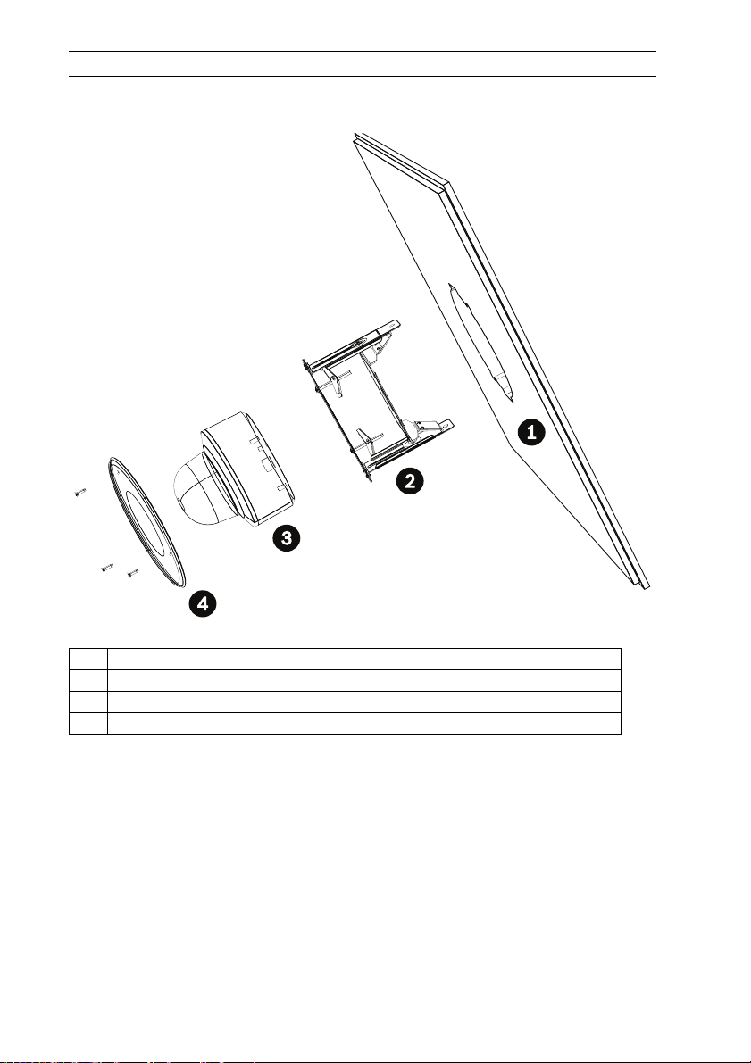
The illustration below shows a typical installation:
Figure 1.1 Typical VDA-NWDFMT installation
1 Drywall ceiling or ceiling tile, 6–23 mm (.24–.91 in.) thick
2 Recess bracket with backplate
3 FlexiDome IP or AutoDome Easy Analog/IP camera
4 Recess trim ring
F.01U.126.944 | 1.0 | 2009.04 Mounting Guide Bosch Security Systems, Inc.
Page 7
Flush Mount Ceiling Kit Unpacking | en 3
i
1.2 Safety Rules
To ensure safety, the following warnings are specified:
– The device must be installed and maintained by skilled
technical personnel.
– Connect the device to a power source corresponding to
the indications given on the marking label.
– Use only the attachments/accessories specified by the
manufacturer.
– Do not use the device near water.
– Do not use the device in the presence of flammable
substances.
– Do not allow children or unauthorized personnel to use the
device.
– Do not block any ventilation openings.
– Refer to the FlexiDome IP Operating Instructions Manual or
to the AutoDome Easy Installation Manual for safety and
wiring information.
– Keep this manual for future reference.
NOTICE!
This user guide has been compiled with great care and the
information it contains has been thoroughly verified. The text
was complete and correct at the time of printing. The ongoing
development of the products may mean that the content of the
user guide can change without notice. Bosch Security Systems
accepts no liability for damage resulting directly or indirectly
from faults, incompleteness or discrepancies between the user
guide and the product described.
Bosch Security Systems, Inc. Mounting Guide F.01U.126.944 | 1.0 | 2009.04
Page 8

4 en | Installing the Recessed Camera Mount Flush Mount Ceiling Kit
!
2 Installing the Recessed Camera
Mount
Use this mount to install a FlexiDome IP (NWD-4xx) camera or
an AutoDome Easy Analog or IP (VEZ series) camera. The VDANWDFMT can be secured to a ceiling tile or to a drywall ceiling.
The ceiling must be between 6–23 mm (.24–.91 in.) thick and
be able to support the combined weight of the camera and the
Flush Mount Ceiling kit.
Note: The table below shows the combined weight of the VDANWDFMT and the following cameras:
Item Weight Combined Weight
VDA-NWDFMT .44 kg (lb)
FlexiDome IP 1.8 kg (3.96 lb) 2.24 kg (4.93 lb)
AutoDome Easy,
IP and Analog
Table 2.1 Combined weights for bracket and cameras
WARNING! Ensure that the ceiling can support the combined
weight of the camera and the Flush Mount Ceiling kit. If the
ceiling is not strong enough, use the VDA-NWDSKT support kit.
Refer to the next section for instructions to install the VDANWDSKT support kit.
1.3 kg (2.86 lb) 1.74 kg (3.83 lb)
F.01U.126.944 | 1.0 | 2009.04 Mounting Guide Bosch Security Systems, Inc.
Page 9

Flush Mount Ceiling Kit Installing the Recessed Camera Mount | en 5
2.1 Installing the VDA-NWDSKT Bracket
The VDA-NWDSKT is a support bracket for the VDA-NWDFMT
Flush Mount Ceiling kit. Use this bracket to add support to a
ceiling tile.
Note: The weight of the VDA-NWDSKT is 1.12 kg (2.46 lb).
1. Remove the ceiling tile.
2. Determine the proper width of the VDA-NWDSKT so that
the side tabs rest against the ceiling T-rails.
3. Align the two panels of the VDA-NWDSKT to the proper
width and secure with the four Phillips head screws
(supplied).
Figure 2.1 VDA-NWDSKT Support Kit
4. Use the VDA-NWDSKT as a template to mark the top of the
ceiling tile; then cut the tile along the template mark.
5. Replace the ceiling tile and place the VDA-NWDSKT on top
of the tile.
Bosch Security Systems, Inc. Mounting Guide F.01U.126.944 | 1.0 | 2009.04
Page 10

6 en | Installing the Recessed Camera Mount Flush Mount Ceiling Kit
!
2.2 Mounting the FlexiDome IP Camera
Use the following image as a reference for the following
procedure:
Figure 2.2 FlexiDome IP components
1 Mounting plate
2 Camera module/base
3 Inner liner
4 Trim ring and dome
1. Determine a secure location for the flush mount ceiling kit.
Refer to Table 2.1, Page 4, for weight information.
2. If the ceiling tile is too thin or if it requires extra support,
refer to Section 2.1 Installing the VDA-NWDSKT Bracket,
Page 5.
WARNING! The ceiling tile or the drywall must be between
6–23 mm (.24–.91 in.) thick.
3. Remove the Recessed Bracket and the template from the
VDA-NWDFMT packaging.
4. Mark the ceiling along the perimeter of the template; then
cut the ceiling along the template mark.
F.01U.126.944 | 1.0 | 2009.04 Mounting Guide Bosch Security Systems, Inc.
Page 11

Flush Mount Ceiling Kit Installing the Recessed Camera Mount | en 7
5. Loosen the three tamper-resistant screws in the FlexiDome
IP Trim Ring (the screws remain in place) using a T20 pinin Torx driver. Remove the Trim Ring with Dome
(Figure 2.2, item 4) by pulling it off of the base.
6. Remove the Inner Liner (Figure 2.2, item 3) by removing it
from the Camera Module/Base.
7. Loosen the three Phillips head screws that secure the
Camera Module/Base (Figure 2.2, item 2) to the Mounting
Plate (Figure 2.2, item 1). Do not remove the hex-head
screws.
8. Detach the safety tether. Set the Mounting Plate aside.
9. Remove the three screws securing the Recess Trim Ring to
the Recess Bracket. Set the screws and the Recess Trim
Ring aside.
10. Align the holes in the Recess Bracket and the Mounting
Plate. Attach the Mounting Plate to the Recess Bracket,
(item 5, below) using the three #10 Flat Washers and the
three #10-24x1/2 in. Phillips Head Screws.
Figure 2.3 Attach mounting plate to backplate
11. Back the toggle bolts off the support screws until they are
close to the end of the threads.
12. Run the power and the network cable (from the ceiling)
through the slot in the Recess Bracket.
Bosch Security Systems, Inc. Mounting Guide F.01U.126.944 | 1.0 | 2009.04
Page 12

8 en | Installing the Recessed Camera Mount Flush Mount Ceiling Kit
13. Slide the Mounting Plate/Bracket assembly into the cutout
in the ceiling tile. You may have to push the support screws
from below to engage the toggle bolts.
Figure 2.4 Insert recess bracket into ceiling
14. Tighten the support screws (item 6, below) until the toggle
bolts grasp the ceiling tile. Do not overtighten the support
screws; it may cause the ceiling tile to break.
Figure 2.5 Tighten toggle bolts
F.01U.126.944 | 1.0 | 2009.04 Mounting Guide Bosch Security Systems, Inc.
Page 13

Flush Mount Ceiling Kit Installing the Recessed Camera Mount | en 9
!
15. Attach a suspension wire to the top of the recess bracket
at one of the points indicated below and then to a
structural element in the ceiling.
WARNING! You must secure the bracket to a structural ceiling
element with a suspension wire to avoid personal injury and
damage to the camera.
Figure 2.6 At tach suspension wire
16. Connect the cables to the connection box, located inside
the Camera Module. Refer to the FlexiDome IP Operating
Instructions for detailed safety instructions and connection
details.
17. Move the excess cabling up into the ceiling.
Bosch Security Systems, Inc. Mounting Guide F.01U.126.944 | 1.0 | 2009.04
Page 14

10 en | Installing the Recessed Camera Mount Flush Mount Ceiling Kit
18. Attach one end of the safety tether to the hook on the
Mounting Plate and the other end to the hook on the
Camera Module/Base.
Figure 2.7 At tach safety tether
7 Safety tether
8 Camera Module/Base
19. Reattach the Camera Module/Base to the Mounting Plate.
20. Push against the underside of the FlexiDome to push the
unit and the bracket up into the ceiling.
21. Adjust the focus of the camera to your desired view. Refer
to the FlexiDome IP Operation Manual for focusing
instructions.
22. Attach the FlexiDome inner liner to the Camera Module/
Base. Then, place the FlexiDome Trim Ring and Dome over
the Camera Module and tighten the three tamper-resistant
screws.
F.01U.126.944 | 1.0 | 2009.04 Mounting Guide Bosch Security Systems, Inc.
Page 15

Flush Mount Ceiling Kit Installing the Recessed Camera Mount | en 11
23. Attach the Recess Trim Ring with the three #8-32 x 5/8 in.
self-tapping screws.
Figure 2.8 Attach recess trim ring
Bosch Security Systems, Inc. Mounting Guide F.01U.126.944 | 1.0 | 2009.04
Page 16

12 en | Installing the Recessed Camera Mount Flush Mount Ceiling Kit
!
2.3 Mounting the AutoDome Analog/IP
Camera
1. Determine a secure location for the flush mount ceiling kit.
Refer to Table 2.1, Page 4, for weight information.
2. If the ceiling tile is too thin or if it requires extra support,
refer to Section 2.1 Installing the VDA-NWDSKT Bracket,
Page 5.
WARNING! The ceiling tile or the drywall must be between
6–23 mm (.24–.91 in.) thick.
3. Remove the Recessed Bracket and the template from the
VDA-NWDFMT packaging.
4. Mark the ceiling tile along the perimeter of the template;
then cut the ceiling tile along the template mark.
5. Remove the three screws securing the brass rings from the
underside of the AutoDome Easy camera (item 1, below).
You will not need the screws or the brass rings for this
installation, but retain these items for future applications.
Figure 2.9 Remove brass rings from AutoDome Easy
F.01U.126.944 | 1.0 | 2009.04 Mounting Guide Bosch Security Systems, Inc.
Page 17

Flush Mount Ceiling Kit Installing the Recessed Camera Mount | en 13
6. Route the wires from the AutoDome Easy through the slot
in the Recess bracket.
7. Align the three holes on the top of the AutoDome Easy with
the three small holes on the Recess Bracket (item 2,
below).
Figure 2.10 Attach AutoDome Easy to backplate
8. Secure the AutoDome Easy to the Recessed Bracket using
the three M2.5 x 8 mm Phillips Head screws.
9. Remove the three screws securing the Recess Trim Ring to
the Recess Bracket. Set the screws and the Recess Trim
Ring aside.
10. Back the toggle bolts off the support screws until they are
close to the end of the threads.
11. Connect the power and video cables to the AutoDome
Easy. Refer to the AutoDome Operating Instructions for
detailed safety instructions and connection details.
Bosch Security Systems, Inc. Mounting Guide F.01U.126.944 | 1.0 | 2009.04
Page 18

14 en | Installing the Recessed Camera Mount Flush Mount Ceiling Kit
12. Slide the AutoDome Easy Bracket assembly into the cutout
in the ceiling tile. You may have to push the support screws
from below to engage the toggle bolts.
Figure 2.11 Insert recess bracket/camera assembly into ceiling
13. Tighten the support screws (item 3, below) until the toggle
bolts grasp the ceiling. Do not overtighten the support
screws; it may cause the ceiling tile to break.
Figure 2.12 Tighten toggle bolts
F.01U.126.944 | 1.0 | 2009.04 Mounting Guide Bosch Security Systems, Inc.
Page 19

Flush Mount Ceiling Kit Installing the Recessed Camera Mount | en 15
!
14. Attach a suspension wire to the top of the recess bracket
at one of the points indicated below and then to a
structural element in the ceiling.
WARNING! You must secure the bracket to a structural ceiling
element with a suspension wire to avoid personal injury and
damage to the camera.
Figure 2.13 Attach suspension wire
15. Push against the underside of the AutoDome Easy to push
the unit and the bracket up into the ceiling.
Bosch Security Systems, Inc. Mounting Guide F.01U.126.944 | 1.0 | 2009.04
Page 20

16 en | Installing the Recessed Camera Mount Flush Mount Ceiling Kit
16. Attach the Recess Trim Ring with the three #8-32 x 5/8 in.
self-tapping screws.
Figure 2.14 Attach recess trim ring
F.01U.126.944 | 1.0 | 2009.04 Mounting Guide Bosch Security Systems, Inc.
Page 21

Page 22

Bosch Security Systems, Inc.
850 Greenfield Road
Lancaster, PA 17601
USA
Telephone +1 800 289 0096
Fax +1 585 223 9180
www.boschsecurity.com
© 2009 Bosch Security Systems, Inc.; F.01U.126.944 | 1.0 | 2009.04;
Data subject to change.
 Loading...