

Bosch VCM8637/00T, VCM8638/00T Installation Instructions Manual
VCM8637/00T - VCM8638/00T
H
C
S
BO
A
R
E
M
A
C
N
O
TI
A
V
ER
S
B
O
D
CC
Installation Instructions
Observation Camera
EN
Manuale d installation
Caméra d Observation
FR
Installationshandbuch
Beobachtungskamera
DE
Manual de instalación
Cámara de Observación
ES
Installatiehandleiding
Observatie Camera
NL
Manuale di installazione
Telecamera di Osservazione
IT
Manual de Instalação
Câmara de Observação
PT
Installations manual
Observationskamera
DA
Installationshandbok
Bevakningskamera
SV
Asennusohje
Val von tak ame ra
SU
Installasjons manual
Overvåkingskamera
NO

8637 & 8638 | Installation Instructions
1
100m
0-50m
200m
300m
5
2
00697
3
4
1415
0or1
100697
Installation Instructions
10
12
13
0or1
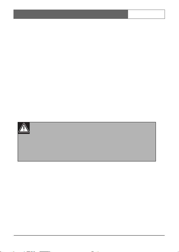
Figure A
FIGURE A
Bosch Security Systems | 2004-06
8637 & 8638 | Installation Instructions
1
F
A
R
<
>
N
E
A
R
3
2
5
4
3
2
5
4
3
2
4-5
2-3
5
4
5
4
3
2
4-5
2-3
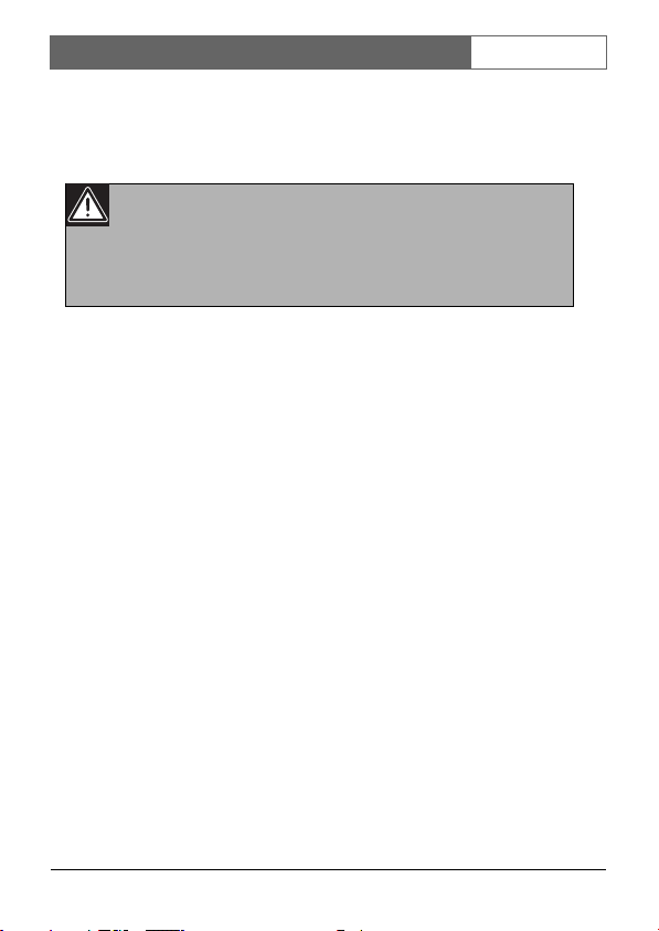
FIGURE B
Bosch Security Systems | 2004-06

8637 & 8638 | Installation Instructions
TABLE OF CONTENTS
ENGLISH ................................................................ 2
FRANÇAIS ............................................................. 6
DEUTSCH .............................................................. 11
ESPAGÑOL ............................................................ 16
NEDERLANDS ...................................................... 21
ITALIANO .............................................................. 25
PORTUGUÊS ......................................................... 30
DANSK .................................................................... 35
SVENSKA ............................................................... 40
SUOMI .................................................................... 44
NORSK .................................................................... 48
GREEK .................................................................... 52
TECHNICAL SPECIFICATION ........................ 57
Bosch Security Systems | 2004-06
8637 & 8638 | Installation Instructions
| 1
ELECTRO MAGNETIC COMPATIBILITY (EMC)
This equipment complies with European rules for EMC according to
EN55013, EN55020 and EN50082-1.
Operation is subject to the following two conditions:
1. This device may not cause harmful interference.
2. This device must accept any interference received, including
interference that may cause undesired operation.
The equipment conforms with the EMC directive and low-voltage
directive.
This device complies to FCC rules under test conditions that included
use of system cables and connectors between system components. If
you have any problems, contact your dealer.
Installation Instructions
WARNINGS
Any unauthorized modification to this equipment may cause
violation of the FCC rules resulting in the revocation of the
authorization to operate the equipment.
To prevent fire or shock hazard, do not expose this accessory to rain
or moisture. Do not attempt to disassemble the camera. In order to
prevent shock and fire hazard, do not remove screws or covers.
There are no user-serviceable parts inside.
WARNING:
The exclamation mark within a triangle is intended to alert
the user to the presence of important operating and
maintenance (servicing) instructions in the literature
accompanying the appliance.
Bosch Security Systems | 2004-06
8637 & 8638 | Installation Instructions
EN | 2
Observation Camera
INTRODUCTION
Your new CCD camera is developed for use with a special
observation system monitor. It features a sensitive microphone thus
registering both images and sound via the monitor, as well as input
contacts for connecting external alarm devices.
INSTALLATION
WARNING:
Disconnect the monitor from the mains supply before
disconnecting a camera or accessory.
Only operating the stand-by key is not sufficient.
When the mains supply is connected, all camera lines are scanned.
The monitor uses this to register the camera configuration of the
system and to check whether any modifications have been made.
Sound
If required, the microphone incorporated in the camera, can be
switched off (fig. A-14).
If an intercom box is included in the camera line, the sound of
camera and intercom box will be reproduced by the monitor.
The illustrations to which this manual refers, are shown on the front
and back jacket flap.
ENGLISHEN
Bosch Security Systems | 2004-06

8637 & 8638 | Installation Instructions
EN | 3
Alarm inputs
The camera has a three-pole terminal block (fig. A-13) for connecting
alarm sensors, such as doorcontacts. For normally open (N.O.)
sensors, connect to contacts N.O.. For normally closed (N.C.) sensors,
connect to contacts N.C..
Position
First you need to determine where the camera is to be installed. The
best results are obtained when the camera looks a little downwards
and not into a bright source of light.
• Hold the camera in your hand at the spot where you want to
install it and check on the monitor whether the camera does
actually cover the required area from that spot.
• Fasten the mounting bracket to the ceiling, the wall, or another
even and firm surface by means of the supplied screws and plugs.
• Tighten the knob (fig. A-3) of the ball-and-socket joint.
• Fasten the camera to the bracket by screwing the mounting hole
in the back or bottom of the camera (fig. A-1) onto the threaded
end (fig. A-2).
• Loosen the knob of the ball-and-socket joint (fig. A-3) and, if
necessary, the screw (fig. A-4) on the mounting bracket and direct
the camera accurately at the object or area you want to have on
screen.
• The knob and screw can be tightened again when the camera is
in the required position.
Remark: The camera can also be mounted on any other camera
tripod standardly provided with a 1/4" 20 UNC thread.
• Check if the cable length compensation (fig. A-15) selector is set
to the correct length. The length set must be the same as the
length of the system cable (0-300m/900ft max.) connecting
monitor and camera.
Bosch Security Systems | 2004-06
8637 & 8638 | Installation Instructions
EN | 4
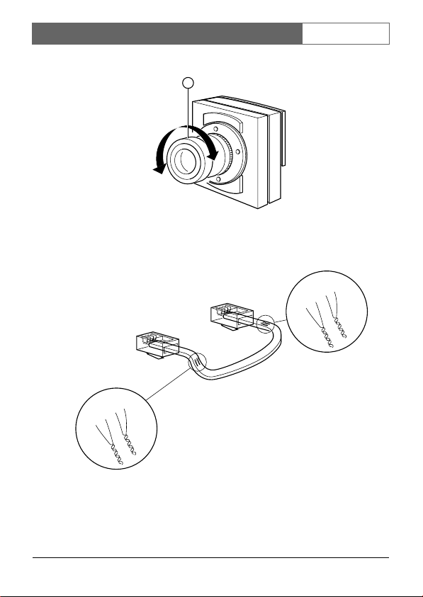
Focus adjustment
Adjust the focus ring (fig. B-1) of the camera lens to obtain an optimal
image sharpness.
Protective cover
For outdoor use a protective cover (fig. A-10) (optional) has to be
used to protect the camera from rain and snow.
System connection
Connect the system cable to the output of the camera (fig. A-12).
The lens
CAUTION:
Do not touch the glass of the lens. This could damage the
delicate coating on its surface. If the lens has to be
cleaned, use a special lens cleaning tissue, available at any
good camera store.
Focus range
The built-in lens provides an optimal image sharpness for objects
between 1 metre and infinity (depth of field).
Cable
A 4-wire system cable (see specifications) is supplied standardly.
For an optimum picture and sound quality a dual 'twisted-pair' cable
should be used.
Bosch Security Systems | 2004-06
8637 & 8638 | Installation Instructions
There is an extensive range of plugs and tools available in the hobby
and professional trade to extend the cable. Always pay attention that
the connection corresponds to figure B.
CAUTION:
The plugs used for the observation system have the same
dimensions as standard telephone plugs. Never connect a
telephone to the camera or system monitor.
The maximum distance that can be bridged (without a cable
extension adapter) between the monitor and the cameras is 300
meters.
EN | 5
TIPS FOR MAINTENANCE
Cleaning
The outside of the camera can be cleaned with a moist fluff-free cloth
or a shammy leather cloth.
When cleaning the objective a special lens cleaning cloth should be
used. Do NOT use cleaning fluids based on alcohol, methylated
spirit, ammonia, etc..
Avoid direct contact with water.
Bosch Security Systems | 2004-06
8637 & 8638 | Manuale d’installation
FR | 6
Caméra d’Observation
INTRODUCTION
Votre caméra CCD est conçue pour être utilisée avec un moniteur
d'observation spécial. Elle est dotée d'un microphone intégré, se qui
luit permet de transmettre le son et l'image au moniteur, et de
contacts d’entrée pour la connexion de dispositifs d’alarme externes.
INSTALLATION
ATTENTION:
Lors de raccordement ou de débranchement d'une caméra
ou d'un accessoire, le moniteur doit toujours être
débranché momentanément de la tension du réseau.
Le seul actionnement de la touche stand-by n'est pas
suffisant.
Lors de raccordement de la tension du réseau, tous les câbles de
caméras sont scannées. Le moniteur établit par là même la
configuration des caméras du système et si d'éventuelles
modifications ont été apportées.
Son
Si vous le souhaitez, le microphone incorporé dans la caméra peut
être mis hors fonction (fig. A-14). Si un module d'interphone est
intégré dans le câble de la caméra, le son de la caméra et celui du
module d'interphone seront reproduits par le moniteur.
Les illustrations auxquelles se réfère le présent manuel sont
présentées dans les dépliants en première et dernière pages de
couverture.
FRFRANÇAISManuale d’installation
Bosch Security Systems | 2004-06

8637 & 8638 | Manuale d’installation
FR | 7
Entrées d’alarme
La caméra a un bloc de connexion tripolaire (fig. A-13) pour la
connexion des détecteurs d’alarme, comme les contacts de porte.
Pour les détecteurs normalement ouverts (N.O.), connectez-les aux
contacts N.O.. Pour les détecteurs normalement fermés (N.C.),
connectez-les aux contacts N.C..
Emplacement
Vous devez préalablement déterminer l'emplacement de la caméra.
Les meilleurs résultats sont obtenus lorsque la caméra est orientée
légèrement vers le bas et non pas vers une source lumineuse intense.
• Tenez la caméra en main dans l'emplacement où vous souhaitez
l'installer et vérifiez sur le moniteur si, depuis cet emplacement, la
caméra couvre efficacement la zone à surveiller.
• Fixez la console de montage au plafond, au mur ou sur toute
autre surface plane et solide, au moyen des vis et chevilles
fournies.
• Serrez le bouton (fig. A-3) du joint à rotules.
• Fixez la caméra à la console en vissant le trou de montage situé à
l'arrière ou en-dessous de la caméra (fig. A-1), sur l'embout fileté
(fig. A-2).
• Desserrez le bouton du joint à rotules (fig. A-3) et, si nécessaire, la
vis (fig. A-4) sur la console de montage, et orientez la caméra avec
précision sur l'objet ou la zone que vous souhaitez reproduire sur
l'écran.
• Le bouton et la vis peuvent ensuite être resserrés une fois que la
caméra se trouve dans la position requise.
Remarque: La caméra peut également être montée sur tout autre
trépied de caméra, normalement livré avec un filetage 1/4" 20
UNC.
Bosch Security Systems | 2004-06

8637 & 8638 | Manuale d’installation
• Vérifiez que le sélecteur de compensation de longueur de câble
(fig. A-15) est mis sur la longueur correcte. La longueur consignée
doit être égale à la longueur du câble système (0-300 mètres
max.) reliant le moniteur à la caméra.
FR | 8
Mise au point
Ajustez la bague de mise au point (fig. B-1) de l’objectif de la caméra
afin d’obtenir une netteté optimale de l’image.
Couvercle protecteur
Pour l'usage en extérieur, un couvercle protecteur (fig. A-10) (en
option) doit être utilisé pour protéger la caméra contre la pluie et la
neige.
Connexion du système
Raccordez le câble du système à la sortie (output) de la caméra (fig.
A-12).
Bosch Security Systems | 2004-06
8637 & 8638 | Manuale d’installation
FR | 9
L'objectif
ATTENTION:
Ne touchez pas le verre de l'objectif. Sinon vous risquez
d'endommager le revêtement sensible de sa surface. Si
vous devez nettoyer l'objectif, faites usage d'un chiffon de
nettoyage spécial pour objectifs, en vente dans les bons
magasins de produits audio-vidéo.
Latitude de mise
L'objectif incorporé fournit une netteté d'image optimale des objets
situés entre 1 mètre et l'infini (profondeur de champ).
Câble
Le système standard est livré avec un câble quadrifilaire (voir
spécifications).
La qualité optimale de l'image et du son exige l'utilisation d'un câble
double 'bifilaire torsadé' standard.
Pour la prolongation du câble, les magasins de bricolage et le
commerce professionnel proposent une grande diversité de fiches et
d'outils. Veillez néanmoins à ce que le raccordement soit conforme à
la figure B.
ATTENTION:
Les prises utilisées pour le système de surveillance ont les
mêmes dimensions que les prises de téléphone standard.
Ne jamais relier un téléphone au moniteur système.
Bosch Security Systems | 2004-06

8637 & 8638 | Manuale d’installation
La distance maximale qui peut relier (sans adaptateur de
prolongation du câble) le moniteur aux caméras est 300 mètres.
FR | 10
CONSEILS D'ENTRETIEN
Nettoyage
Vous pouvez nettoyer l'extérieur de la caméra avec un chiffon sans
poils, humide, ou une peau de chamois.
Pour le nettoyage de l'objectif, utilisez un chiffon de nettoyage spécial
pour objectifs. N'UTILISEZ PAS de nettoyants à base d'alcool,
d'alcool à brûler, d'ammoniac etc..
Evitez tout contact direct avec l'eau.
Bosch Security Systems | 2004-06
8637 & 8638 | Installationshandbuch
DE | 11
Beobachtungskamera
InstallationshandbuchDEUTSCHDE
EINLEITUNG
Ihre neue CCD-Kamera eignet sich für den Anschluß an einen
speziellen Überwachungsmonitor. Sie ist mit einem empfindlichen
Mikrofon ausgestattet, so daß sowohl Bild als auch Ton über den
Monitor registriert werden können, und sie besitzt ein Anschluß für
externe Alarmvorrichtungen.
ANSCHLUSS
WARNUNGSHINWEIS:
Wenn eine Kamera oder ein Zubehörteil angeschlossen
wird, muß der Monitor immer spannungsfrei gemacht
werden.
Es genügt nicht, nur die Stand-by-Taste zu drücken!
Wenn die Netzspannung angeschlossen wird, werden alle KameraLeitungen abgetastet. Der Monitor notiert hierbei die KameraKonfiguration des Systems und kontrolliert, ob irgendwelche
Änderungen vorgenommen worden sind.
Ton
Falls erforderlich, kann das in die Kamera integrierte Mikrofon
ausgeschaltet werden (Abb. A-14). Falls in die Kameraleitung eine
Gegensprechbox integriert ist, gibt der Monitor den Ton der Kamera
und den der Gegensprechanlage wieder.
Die Abbildungen zu dieser Betriebsanleitung befinden sich auf der
Vorder- und Rückseite des Umschlags.
Bosch Security Systems | 2004-06

8637 & 8638 | Installationshandbuch
DE | 12
Alarmeingänge
Die Kamera besitzt eine 3polige Anschlußklemme (Abb. A-13) zum
Anschluß von Alarmsignalgebern, wie beispielsweise Türkontakten.
Für Schließersensoren verbinden Sie die Kontakte N.O.. Für
Öffnersensoren verbinden Sie die Kontakte N.C..
Position
Zuerst müssen Sie feststellen, an welcher Stelle die Kamera installiert
werden muß. Das beste Ergebnis wird erreicht, wenn die Kamera
etwas nach unten und nicht in eine helle Lichtquelle gerichtet wird.
• Halten Sie die Kamera an der Stelle, an der Sie sie installieren
möchten, in der Hand und kontrollieren Sie auf dem Monitor, ob
die Kamera von dieser Stelle aus auch wirklich den gewünschten
Bereich abdeckt.
• Befestigen die Befestigungsklammern mit den mitgelieferten
Schrauben und Muttern an der Decke, der Wand oder auf einer
anderen ebenen, stabilen Fläche.
• Ziehen Sie den Knopf des Drehgelenks fest (Abb. A-3).
• Befestigen Sie die Kamera an den Befestigungsklammern. Hierzu
schrauben Sie das Gewindestück (Abb. A-2) in die
Befestigungslöcher an der Rückseite oder unter der Kamera
(Abb. A-1).
• Lockern Sie den Knopf des Drehgelenks (Abb. A-3) und, falls
erforderlich, die Schraube (Abb. A-4) an den
Befestigungsklammern und richten Sie die Kamera genau auf das
Objekt oder den Bereich, den Sie auf dem Bildschirm sehen
möchten.
• Der Knopf und die Schraube können wieder festgestellt werden,
wenn sich die Kamera in der gewünschten Position befindet.
Anmerkung: Die Kamera kann auch auf alle Kamerastative
montiert werden, die standardmäßig ein 1/4" 20 UNC Gewinde
haben.
Bosch Security Systems | 2004-06

8637 & 8638 | Installationshandbuch
• Kontrollieren Sie, ob der Kabellängenkompensierungswähler
(Abb. A-15) auf die richtige Länge eingestellt ist. Die eingestellte
Länge muß mit der Länge des Systemkabels (0 - max. 300m)
zwischen Monitor und Kamera übereinstimmen.
DE | 13
Einstellen der Bildschärfe
Stellen Sie den Bildschärfenring (Abb. B-1) des Kameraobjektivs so
ein, daß die Bildschärfe optimal ist.
Schutzgehäuse
Zum Schutz der Kamera gegen Regen und Schnee ist bei Einsatz im
Freien ein Schutzgehäuse (Abb. A-10) zu verwenden.
Anschließen des Systems
Verbinden Sie das Systemkabel an die Ausgangsbuchsen der Kamera
(Abb. A-12).
Bosch Security Systems | 2004-06
8637 & 8638 | Installationshandbuch
DE | 14
Das Objektiv
ACHTUNG:
Berühren Sie niemals das Glas des Objektivs, sie können
hierdurch die empfindliche Oberfläche beschädigen. Wenn
das Objektiv gereinigt werden muß, benutzen Sie bitte ein
Spezial-Reinigungstuch, das in jedem guten Fotogeschäft
erhältlich ist.
Fokusbereich
Das eingebaute Objektiv ermöglicht eine optimale Bildschärfe für
Objekte mit einem Abstand von einem Meter bis unendlich
(Feldtiefe).
Kabel
Standardmäßig wird ein vieradriges Systemkabel mitgeliefert (siehe
technische Einzelheiten).
Zum Erhalt einer optimalen Bild- und Tonqualität wird ein verdrilltes
Doppelleiterpaar benutzt.
In Heimwerkerläden und im Fachhandel ist eine große Auswahl
Stecker und Verlängerungsmaterial erhältlich. Sie müssen darauf
achten, das die Verbindungen der Abb. B entsprechen.
VORSICHT:
Die Stecker, die für das Überwachungssystem verwendet
werden, haben die gleiche Gröbe wie normale
Telefonstecker. Unter keinen Umständen Telefongeräte an
die Kamera oder den Systemmonitor anschließen.
Bosch Security Systems | 2004-06

8637 & 8638 | Installationshandbuch
Der maximale Abstand, der ohne einen Kabelverlängerungsadapter
zwischen Monitor und den Kameras überbrückt werden kann,
beträgt 300m.
DE | 15
TIPS FÜR DIE WARTUNG
Reinigung
Sie können den Monitor mit einem feuchten flusenfreien Tuch oder
einem Fensterleder reinigen.
Benutzen Sie für die Reinigung des Objektivs ist ein spezielles
Objektivreinigungstuch. Für die Reinigung dürfen Sie KEINE
alkohol-, methanoloder ammoniakhaltigen und dergleichen oder
flüssigen Reinigungsmittel verwenden.
Vermeiden Sie eine direkte Berührung mit Wasser.
Bosch Security Systems | 2004-06
 Loading...