

Bosch VC86775T, VC86785T Installation Instructions Manual
VC86775T & VC86785T
R
A
E
N
>
<
R
A
F
Installation Instructions
Observation Camera
EN
Manuale d'installation
Caméra d 'Observation
FR
Manual de instalación
Cámara de Observación
ES
Bosch Security Systems | 2004-07
VC86775T & VC86785T | Installation Instructions
Installation Instructions
1
2
5
3
4
00697
12
100697
13
10
0X1
200m
0-50m
100m
300m
0X1
1415
FIGURE A
Bosch Security Systems | 2004-07
VC86775T & VC86785T | Installation Instructions
5
4
3
2
4-5
2-3
5
4
3
2
4-5
2-3
5
4
3
2
5
4
3
2
R
A
E
N
>
<
R
A
F
1
CL 76610011_004.AI
FIGURE B

Bosch Security Systems | 2004-07
VC86775T & VC86785T | Installation Instructions
TABLE OF CONTENTS
ENGLISH ................................................................ 1
FRANÇAIS ............................................................. 8
ESPAÑOL ............................................................... 15
TECHNICAL SPECIFICATIONS ...................... 27

Bosch Security Systems | 2004-07
EN | 1
VC86775T & VC86785T | Installation Instructions
FCC DECLARATION
Installation InstructionsENGLISHEN
This device complies with part 15 of the FCC rules.
Operation is subject to the following two conditions:
1. This device may not cause harmful interference.
2. This device must accept any interference received, including
interference that may cause undesired operation.
This equipment has been tested and found to comply with the limits
for a class B digital device, pursuant to Part 15 of the FCC Rules.
These limits are designed to provide reasonable protection against
harmful interference in a residential installation.
This equipment generates, uses and can radiate radio frequency
energy and, if not installed and used in accordance with the
instructions, may cause harmful interference to radio
communications. However, there is no guarantee that interference
will not occur in a particular installation. If this equipment does cause
harmful interference to radio or television reception, which can be
determined by turning the equipment off and on, the user is
encouraged to try to correct the interference by one or more of the
following measures:
• Reorient or relocate the receiving antenna.
• Increase the distance between the equipment and the receiver.
• Connect the equipment to a power socket on a circuit different
from that to which the receiver is connected.
• Consult the dealer or an experienced radio/TV technician for
help.
Bosch Security Systems | 2004-07
EN | 2
VC86775T & VC86785T | Installation Instructions
WARNING
Any unauthorized modification to this equipment could result in the
revocation of the authorization to operate the equipment.
WARNING:
To prevent fire or shock hazard, do not expose this camera
to rain or moisture. Do not attempt to disassemble the
camera. In order to prevent shock and fire hazard, do not
remove screws or covers. There are no user-serviceable
parts inside.
Bosch Security Systems | 2004-07
EN | 3
VC86775T & VC86785T | Installation Instructions
Observation Camera
INTRODUCTION
Your new CCD camera is developed for use with a special
observation system monitor. It features a sensitive microphone thus
registering both images and sound via the monitor, as well as input
contacts for connecting external alarm devices.
INSTALLATION
When the mains supply is connected, all camera lines are scanned.
The monitor uses this to register the camera configuration of the
system and to check whether any modifications have been made.
Sound
If required, the microphone incorporated in the camera, can be
switched off (fig. A-14).
If an intercom box is included in the camera line, the sound of
camera and intercom box will be reproduced by the monitor.
The illustrations to which this manual refers, are shown on the front
and back jacket flap.
WARNING:
Disconnect the monitor from the mains supply before
disconnecting a camera or accessory.
Only operating the stand-by key is not sufficient.

Bosch Security Systems | 2004-07
EN | 4
VC86775T & VC86785T | Installation Instructions
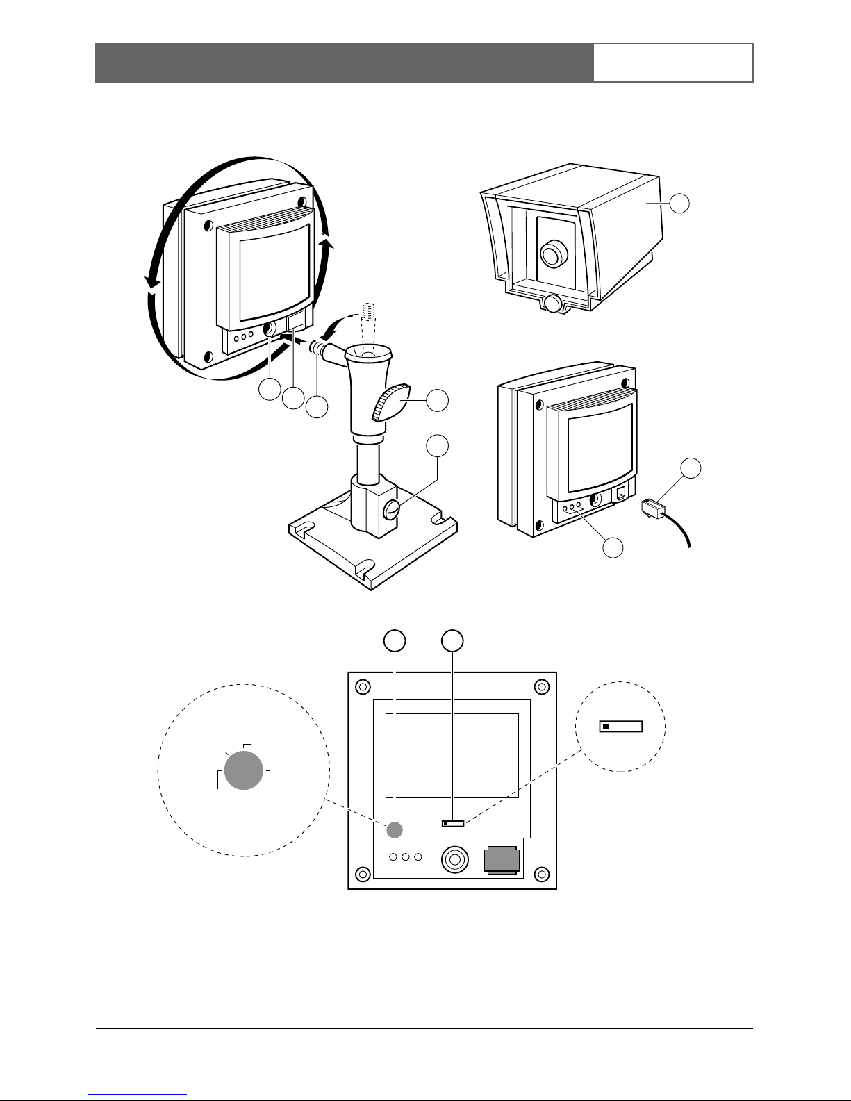
Alarm inputs
The camera has a three-pole terminal block (fig. A-13) for connecting
alarm sensors, such as doorcontacts. For normally open (N.O.)
sensors, connect to contacts N.O.. For normally closed (N.C.) sensors,
connect to contacts N.C..
Position
First you need to determine where the camera is to be installed. The
best results are obtained when the camera looks a little downwards
and not into a bright source of light.
• Hold the camera in your hand at the spot where you want to
install it and check on the monitor whether the camera does
actually cover the required area from that spot.
• Fasten the mounting bracket to the ceiling, the wall, or another
even and firm surface by means of the supplied screws and plugs.
• Tighten the knob (fig. A-3) of the ball-and-socket joint.
• Fasten the camera to the bracket by screwing the mounting hole
in the back or bottom of the camera (fig. A-l) onto the threaded
end (fig. A-2).
• Loosen the knob of the ball-and-socket joint (fig. A-3) and, if
necessary, the screw (fig. A-4) on the mounting bracket and direct
the camera accurately at the object or area you want to have on
screen.
• The knob and screw can be tightened again when the camera is
in the required position.
Remark: The camera can also be mounted on any other camera
tripod standardly provided with a 1/4" 20 UNC thread.
• Check if the cable length compensation (fig. A-15) selector is set
to the correct length. The length set must be the same as the
length of the system cable (0-300m/900ft max.) connecting
monitor and camera.
Bosch Security Systems | 2004-07
EN | 5
VC86775T & VC86785T | Installation Instructions
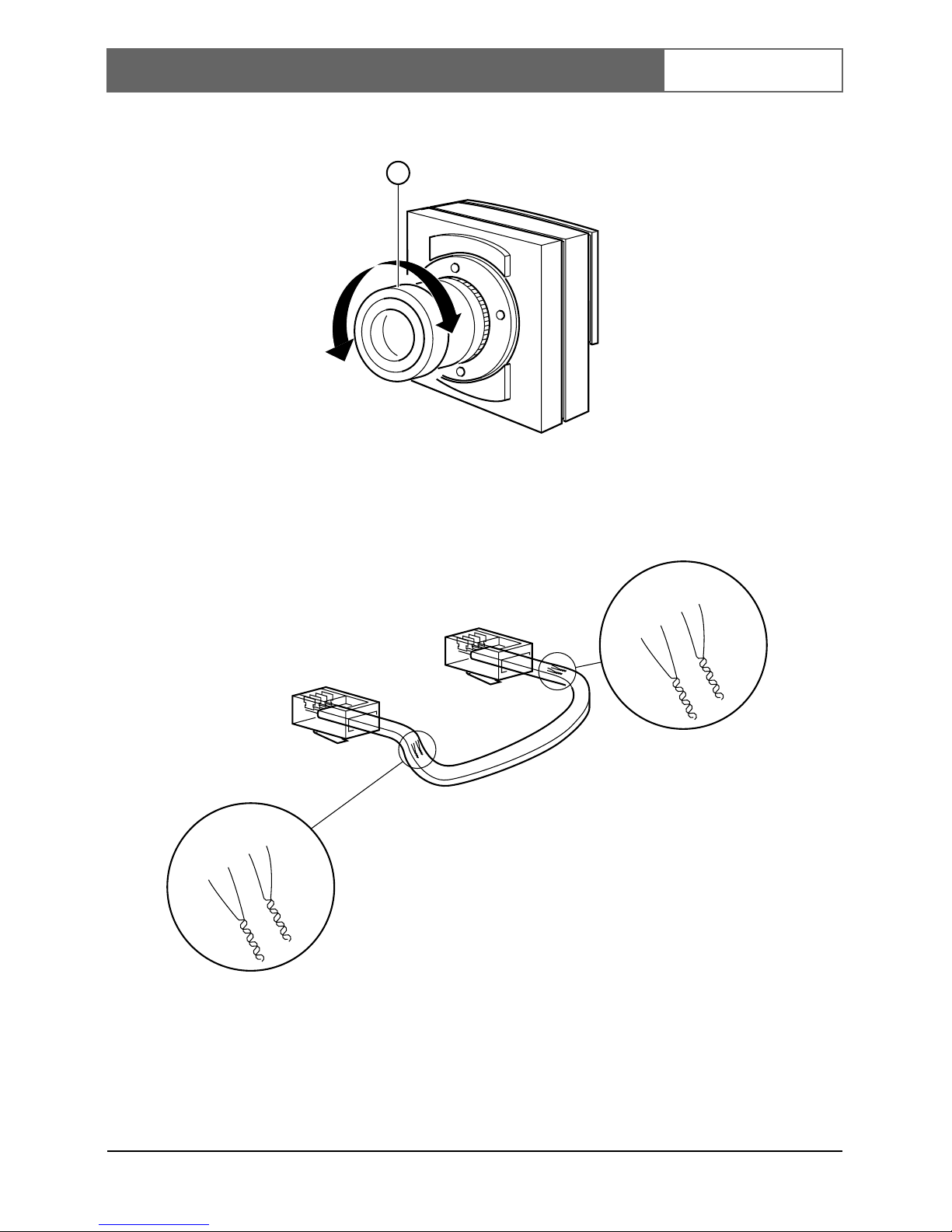
Focus adjustment
Adjust the focus ring (fig. B-l) of the camera lens to obtain an optimal
image sharpness.
Remark: If still no sharp object image is obtained, you should
adjust the back-focus of the camera.
Back-focus adjustment
• Set focus adjustment ring to Far or Infinity (fig. B-2).
• Aim the camera at an object at least 15 metres/45 feet away.
Remark: When bright light sources are positioned within the
camera view field; dim the light source.
• Loosen the back-focus locking ring (fig. B-3).
• Rotate the lens, including the CS-mount ring, until the video
image on the monitor is sharp.
• Tighten the back-focus locking ring (fig. B-3), while keeping the
lens in place.
Protective cover
For outdoor use a protective cover (fig. A-10) (optional) has to be
used to protect the camera from rain and snow.
System connection
Connect the system cable to the output of the camera (fig. A-12).
CAUTION:
Back-focus adjustment is only necessary when no sharp
object image is obtained with the focus adjustment ring.
Bosch Security Systems | 2004-07
EN | 6
VC86775T & VC86785T | Installation Instructions
The lens
Focus range
The built-in lens provides an optimal image sharpness for objects
between 1 metre and infinity (depth of field).
Cable
A 4-wire system cable (see specifications) is supplied standardly.
For an optimum picture and sound quality a standard dual 'twistedpair' cable should be used.
There is an extensive range of plugs and tools available in the hobby
and professional trade to extend the cable. Always pay attention that
the connection corresponds to figure B.
The maximum distance that can be bridged (without a cable
extension adapter) between the monitor and the cameras is 300
meters.
CAUTION:
Do not touch the glass of the lens. This could damage the
delicate coating on its surface. If the lens has to be
cleaned, use a special lens cleaning tissue, available at
any good camera store.
CAUTION:
The plugs used for the observation system have the same
dimensions as standard telephone plugs. Never connect a
telephone to the camera or system monitor.
 Loading...