

Bosch UT-L 14, UT-L 8, UT-L 4, UT-L 18, UT-L 12 Technical Manual
...
Technical guide
Heating boiler
UNIMAT
UT-L
6 720 807 794(2013/04)EN
2 | Table of contents
UNIMAT6 720 807 794 (2013/04)
Table of contents
1 Oil/gas special boilers . . . . . . . . . . . . . . . . . . . . . 4
1.1 Types and heating output . . . . . . . . . . . . . . 4
1.2 Overview of models . . . . . . . . . . . . . . . . . . 4
1.3 Possible applications . . . . . . . . . . . . . . . . . 4
1.4 Features and benefits . . . . . . . . . . . . . . . . . 4
2 Basic principles . . . . . . . . . . . . . . . . . . . . . . . . . . 5
2.1 Basic principles of condensing technology . 5
2.1.1 Net and gross calorific values . . . . . . . . . . . 5
2.1.2 Boiler efficiency above 100 % . . . . . . . . . . . 5
2.2 Making optimal use of condensing
technology . . . . . . . . . . . . . . . . . . . . . . . . . 6
2.2.1 Matching to the heating system . . . . . . . . . 6
2.2.2 High standard seasonal efficiency [to DIN] 7
2.2.3 Design information . . . . . . . . . . . . . . . . . . . 7
2.3 Economic viability considerations . . . . . . . 7
2.3.1 Simplified comparison of conventional
boilers and condensing boilers or boilers
with condensing heat exchangers . . . . . . . 7
3 Technical description . . . . . . . . . . . . . . . . . . . . . . 8
3.1 UNIMAT UT-L boiler . . . . . . . . . . . . . . . . . . . 8
3.1.1 Equipment overview . . . . . . . . . . . . . . . . . . 8
3.1.2 Function principle . . . . . . . . . . . . . . . . . . . . 9
3.2 UNIMAT UT-L boiler . . . . . . . . . . . . . . . . . . 10
3.2.1 Version overview . . . . . . . . . . . . . . . . . . . . 10
3.2.2 Function principle . . . . . . . . . . . . . . . . . . . 11
3.3 Dimensions and specification for the
flue gas heat exchangers . . . . . . . . . . . . . 12
3.3.1 UNIMAT UT-L boiler . . . . . . . . . . . . . . . . . . 12
3.3.2 Integrated heat exchanger without
condensing technology — ECO 7 . . . . . . . 14
3.3.3 Integrated heat exchanger with
condensing technology — ECO6 . . . . . . . . 16
3.3.4 Stand-alone flue gas heat exchanger
without condensing technology — ECO 7 . 18
3.3.5 Stand-alone flue gas heat exchanger
with condensing technology — ECO 6 . . . 20
3.4 Connections . . . . . . . . . . . . . . . . . . . . . . . 22
3.4.1 Flow and return . . . . . . . . . . . . . . . . . . . . 22
3.4.2 Flue outlet connection . . . . . . . . . . . . . . . 22
3.4.3 Connector . . . . . . . . . . . . . . . . . . . . . . . . . 23
3.5 Characteristics . . . . . . . . . . . . . . . . . . . . . 24
3.5.1 Pressure loss on the water side . . . . . . . . 24
3.5.2 Pressure loss on the hot gas side . . . . . . . 25
3.5.3 Combustion chamber volume load . . . . . . 27
3.5.4 Boiler efficiency, standard seasonal
efficiency [to DIN] and standby loss . . . . 28
3.5.5 Flue gas temperature . . . . . . . . . . . . . . . . 30
4 Burner . . . . . . . . . . . . . . . . . . . . . . . . . . . . . . . . . 32
4.1 General requirements . . . . . . . . . . . . . . . . 32
4.2 Information on burner selection . . . . . . . . 32
4.3 Matched pressure-jet burners . . . . . . . . . 32
4.4 Combustion details for the UNIMAT UT-L
boilers . . . . . . . . . . . . . . . . . . . . . . . . . . . 33
5 Regulations and operating conditions . . . . . . . 35
5.1 Extracts from the regulations . . . . . . . . . 35
5.2 German Immissions Act (BImSchG) . . . . 36
5.2.1 Table extracted from the 1st BImSchV
“Small and medium-sized combustion
systems” . . . . . . . . . . . . . . . . . . . . . . . . . . 36
5.2.2 Information on flue gas tests pursuant to
BImSchV/TA Luft . . . . . . . . . . . . . . . . . . . 37
5.3 Operating requirements . . . . . . . . . . . . . 38
5.3.1 Operating conditions . . . . . . . . . . . . . . . . 38
5.3.2 Fuel . . . . . . . . . . . . . . . . . . . . . . . . . . . . . 38
5.3.3 Corrosion protection in heating systems 38
5.3.4 Corrosion protection if system out of
use for long periods . . . . . . . . . . . . . . . . . 39
5.3.5 Guidelines for water quality . . . . . . . . . . 39
5.3.6 Minimum requirements of water analyses
for designing a water treatment system . . 41
6 Sound pressure level from noise in the boiler
system . . . . . . . . . . . . . . . . . . . . . . . . . . . . . . . . 42
6.1 Sound emissions from the boiler system 42
6.2 Noise in the installation room . . . . . . . . . 42
6.3 Noise at the chimney outlet . . . . . . . . . . 42
7 Boiler control and control system . . . . . . . . . . 43
7.1 CFB 810 control unit with CME 930
auxiliary module . . . . . . . . . . . . . . . . . . . . 43
7.2 CFB 930 and CFB 910 control units . . . . 44
7.3 Side control unit holder . . . . . . . . . . . . . 45
7.4 UNIMATIC display units and control units 46
7.5 BCO boiler control . . . . . . . . . . . . . . . . . 46
8 DHW heating . . . . . . . . . . . . . . . . . . . . . . . . . . . 47
8.1 Systems for DHW heating . . . . . . . . . . . . 47
8.2 DHW temperature control . . . . . . . . . . . . 47
9 System examples . . . . . . . . . . . . . . . . . . . . . . . 47
9.1 Information regarding all system
examples . . . . . . . . . . . . . . . . . . . . . . . . . 47
9.1.1 Hydraulic connection . . . . . . . . . . . . . . . . 48
9.1.2 Control system . . . . . . . . . . . . . . . . . . . . 48
9.1.3 DHW heating . . . . . . . . . . . . . . . . . . . . . . 48
9.1.4 Pipework schemes . . . . . . . . . . . . . . . . . 49
9.2 Safety equipment to DIN-EN 12828 . . . . 52
9.2.1 Requirements . . . . . . . . . . . . . . . . . . . . . 52
9.2.2 Layout of safety components to DIN-EN
12828 . . . . . . . . . . . . . . . . . . . . . . . . . . . . 52
9.2.3 Safety equipment for the flue gas heat
exchanger . . . . . . . . . . . . . . . . . . . . . . . . . 53
9.2.4 Maximum operating flow temperatures . 53
9.3 Sizing and installation information . . . . . 53

Table of contents | 3
6 720 807 794 (2013/04)UNIMAT
9.3.1 Boiler circuit pump in the bypass as shunt
pump . . . . . . . . . . . . . . . . . . . . . . . . . . . . 53
9.3.2 Boiler circuit pump as primary circuit pump .
55
9.3.3 Hydraulic balancing line . . . . . . . . . . . . . 56
9.4 1-boiler system with UNIMAT UT-L boiler:
boiler and heating circuit control unit . . .57
9.5 1-boiler system with UNIMAT UT-Lboiler:
boiler and heating circuit control unit
with hydraulic separation . . . . . . . . . . . . . 58
9.6 1-boiler system with UNIMAT UT-L boiler:
boiler circuit control unit . . . . . . . . . . . . . 59
9.7 1-boiler system with UNIMAT UT-L boiler:
boiler circuit control unit with hydraulic
separation . . . . . . . . . . . . . . . . . . . . . . . . 60
9.8 2-boiler system with two UNIMAT UT-L
boilers: boiler circuit control unit with
hydraulic separation . . . . . . . . . . . . . . . . . 61
9.9 1-boiler system with UNIMAT UT-L boiler
with flue gas heat exchanger: boiler circuit
control unit . . . . . . . . . . . . . . . . . . . . . . . .62
9.10 1-boiler system with UNIMAT UT-L boiler
with condensing heat exchanger: boiler
circuit control unit with hydraulic
separation . . . . . . . . . . . . . . . . . . . . . . . . 63
9.11 2-boiler system with UNIMAT UT-L boiler
without flue gas heat exchanger and UT-L
boiler with condensing heat exchanger:
boiler circuit control unit with hydraulic
separation . . . . . . . . . . . . . . . . . . . . . . . . 64
9.12 UNIMAT UT-L boiler with flue gas heat
exchanger or condensing heat exchanger:
return temperature raising . . . . . . . . . . . . 65
10 Fitting . . . . . . . . . . . . . . . . . . . . . . . . . . . . . . . . 66
10.1 Transport and handling . . . . . . . . . . . . . . 66
10.1.1 Delivery method and transport options . . 66
10.1.2 Handling dimensions . . . . . . . . . . . . . . . . 66
10.2 Design of installation rooms and
combustion air supply . . . . . . . . . . . . . . . 67
10.2.1 Installation location . . . . . . . . . . . . . . . . . 67
10.2.2 Combustion air supply . . . . . . . . . . . . . . 67
10.3 Installation dimensions . . . . . . . . . . . . . . 69
10.3.1 Installation room dimensions for the
UNIMAT UT-L boilers . . . . . . . . . . . . . . . . 69
10.3.2 Installation room dimensions for the
UNIMAT UT-L boilers with flue gas heat
exchanger . . . . . . . . . . . . . . . . . . . . . . . . . 70
10.4 Additional safety equipment to
DIN-EN 12828 . . . . . . . . . . . . . . . . . . . . . . 71
10.4.1 Safety equipment . . . . . . . . . . . . . . . . . . 71
10.4.2 Boiler safety equipment assembly to
DIN-EN 12828 . . . . . . . . . . . . . . . . . . . . . . 71
10.4.3 Intermediate return piece . . . . . . . . . . . . 72
10.4.4 Safety valve . . . . . . . . . . . . . . . . . . . . . . . 73
10.4.5 Flash trap to DIN-EN 12828 . . . . . . . . . . . 75
10.4.6 Return flow temperature safeguard
set (maintaining version) . . . . . . . . . . . . . 76
10.5 Additional devices for sound insulation . . 77
10.5.1 Requirements . . . . . . . . . . . . . . . . . . . . . . 77
10.5.2 Flue gas silencer . . . . . . . . . . . . . . . . . . . 77
10.5.3 Burner silencer hoods . . . . . . . . . . . . . . . 77
10.5.4 Boiler mounts to attenuate structure-
borne noise . . . . . . . . . . . . . . . . . . . . . . . 77
10.5.5 Boiler foundation . . . . . . . . . . . . . . . . . . . 78
10.6 Further accessories . . . . . . . . . . . . . . . . . 79
10.6.1 Drain connection and blow-down valve
assembly . . . . . . . . . . . . . . . . . . . . . . . . . 79
10.6.2 Walk-on boiler cover . . . . . . . . . . . . . . . . 79
11 Flue system . . . . . . . . . . . . . . . . . . . . . . . . . . . . 81
11.1 Requirements . . . . . . . . . . . . . . . . . . . . . . 81
11.1.1 General notes . . . . . . . . . . . . . . . . . . . . . . 81
11.1.2 Special information for flue systems of
boilers with condensing flue gas heat
exchangers . . . . . . . . . . . . . . . . . . . . . . . 81
11.1.3 Material requirements for flue systems of
boilers with condensing heat exchangers 81
12 Condensate drain . . . . . . . . . . . . . . . . . . . . . . . 82
12.1 Condensate . . . . . . . . . . . . . . . . . . . . . . . 82
12.1.1 Creation . . . . . . . . . . . . . . . . . . . . . . . . . . 82
12.1.2 Condensate disposal . . . . . . . . . . . . . . . . 82
12.2 Neutralising system NE 2.0 . . . . . . . . . . . 82
12.2.1 Installation . . . . . . . . . . . . . . . . . . . . . . . . 82
12.2.2 Equipment level . . . . . . . . . . . . . . . . . . . . 82
12.2.3 Neutralising agent . . . . . . . . . . . . . . . . . . 82
12.2.4 Pump output graph . . . . . . . . . . . . . . . . . 82
Keyword index . . . . . . . . . . . . . . . . . . . . . . . . . . 84
4 | Oil/gas special boilers
UNIMAT6 720 807 794 (2013/04)
1 Oil/gas special boilers
1.1 Types and heating output
The UNIMAT UT-L boilers are special boilers for positive
pressure combustion in accordance with the
requirements of EN 303. They are constructed with
reference to the guidelines of the relevant TRD 300.
Bosch offers these boilers in the output range from
650 kW to 19200 kW.
The boilers are designed to produce low pressure hot
water with no more than 110 °C (shutdown temperature
of the high limit safety cut-out) for heating systems that
correspond to the requirements of DIN-EN 12828. The
boiler is available with excess pressures of 6 bar, 10 bar
and 16 bar.
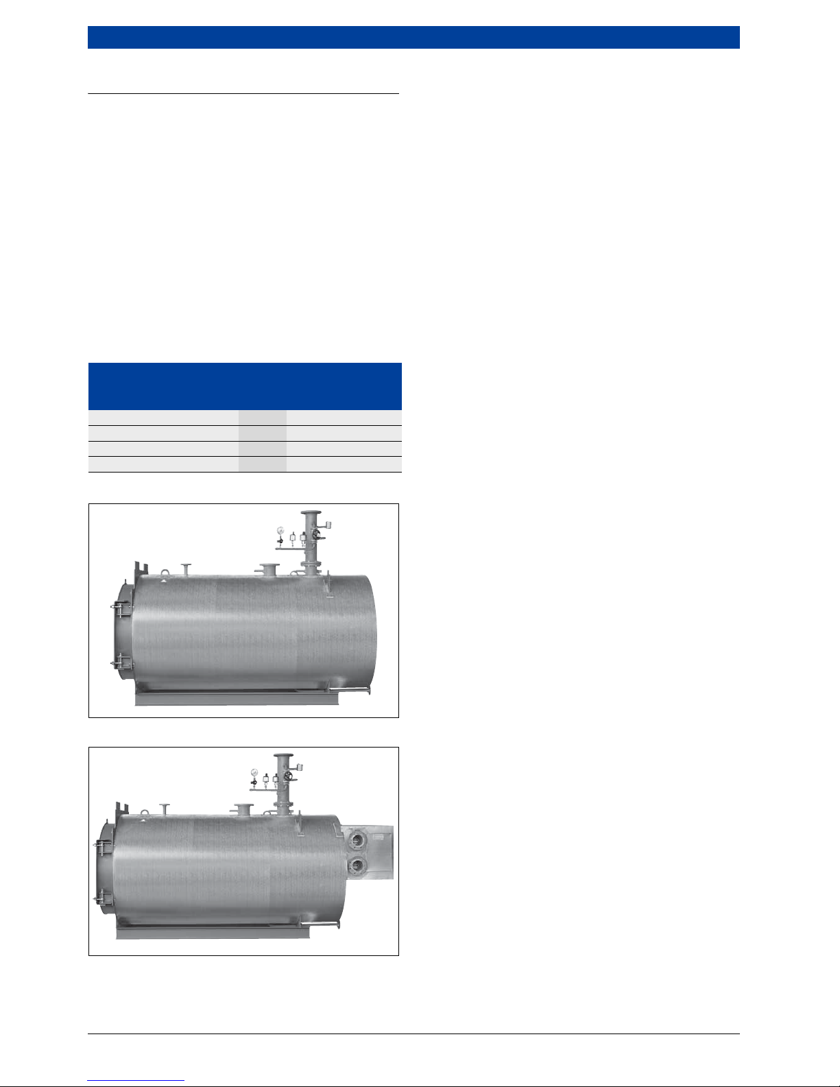
1.2 Overview of models
Fig. 1 UNIMAT UT-L boiler without heat exchanger
Fig. 2 UNIMAT UT-L boiler with heat exchanger or
condensing heat exchanger
1.3 Possible applications
The modular design and additional equipment mean the
boiler can be used in any application. A suitable version
is available for the requirements of any project.
The optimum application is in large-scale systems, e.g.
hospitals, industrial plants, district heating centres,
heating stations and commercial operations.
1.4 Features and benefits
• 3-pass design
The 3-pass technology enables the UNIMAT UT-L
boilers to achieve outstanding combustion figures.
• Optimised temperature characteristics
The boilers have a generously sized secondary heating
surface in the second pass, designed as a double row.
The inner hot gas reversing chamber, which is
completely surrounded by water, enables very low
temperatures in the front reversing area from the
second to the third pass. This significantly reduces
the thermal load of the door.
• Compact construction
The symmetrical secondary heating surfaces,
arranged in a circle around the combustion chamber,
enable the compact construction of these boilers.
This means they have a low weight and require only a
small floor area for installation. The burner door can
close on the right hand or left hand side.
• Environmentally responsible with low emissions
The 3-pass design and water-cooled combustion
chamber offer ideal conditions for operation with low
emissions, especially in conjunction with the
advanced burners that are matched to the boilers.
Meeting the highest demands regarding low
emissions, especially with oil combustion, is no
problem for the UNIMAT UT-L boiler with its
particularly large combustion chambers.
• Economic viability
Extremely high efficiency is possible, subject to the
temperature of the heating medium and the boiler
load. The radiation losses of the boiler are negligibly
low and the full utilisation of the burner control range
enables good efficiency at partial load.
• Operational reliability
Due to the optimised design of the combustion
chamber and the water guide system, the UNIMAT UTL boiler is very reliable and safe in operation. The low
water capacity enables a short heat-up time. This
means the dew point range in the heat-up phase is
quickly passed.
• Even load distribution
For even load distribution, the boiler is equipped with
a base frame of channel sections. If the floor of the
boiler room is even, an additional boiler foundation is
not required.
• Simple maintenance
The front boiler door can be pivoted right out, and can
be opened easily even when the burner is fitted. When
the door is open, the combustion chamber and
secondary heating surface are freely accessible, and
can be cleaned quickly and easily. The reversing
chamber is visible through the combustion chamber.
As an option, an inspection port on the water side is
available. This gives a better view of the heating
Unit UNIMAT UT-L boiler
Boiler size 650 to
19200
Safety temperature °C ≤ 110
Safety pressure bar ≤ 16
Measurements page 12 f.
Technical Data page 25
Table 1 Overview of UNIMAT boiler models UT-L
6 720 642 347-82.1il
6 720 642 347-83.1il
Basic principles | 5
6 720 807 794 (2013/04)UNIMAT
surfaces. It means the heating surfaces can be viewed
from the water chamber.
• Matching system technology
Numerous matching components are available for all
boilers, which enable optimisation of the entire
system.
2 Basic principles
2.1 Basic principles of condensing
technology
2.1.1 Net and gross calorific values
The net calorific value Hi (formerly Hu) specifies the
amount of heat that can be obtained from one cubic
metre of gas or one kilogram of fuel oil. With this
reference figure, the products of combustion are
present in a gaseous state.
Compared to the net calorific value Hi, the gross calorific
value H
s
(formerly Ho) also contains the condensation
heat from the water vapour as additional energy.
2.1.2 Boiler efficiency above 100 %
The condensing boiler or boiler with condensing heat
exchanger utilises not only the net calorific value H
i
in
order to produce heat, but also the gross calorific value
H
s
of a fuel.
For all efficiency calculations in German and European
standards, the net calorific value Hi is always selected at
100 % as a reference figure, meaning that a boiler
efficiency of over 100 % can result. This is the only way
of comparing conventional boilers and condensing
boilers or boilers with condensing heat exchangers.
Boiler efficiency can be raised by up to 15 % in
comparison with conventional boilers. Compared with
older systems, it is even possible to save up to 40 %
energy.
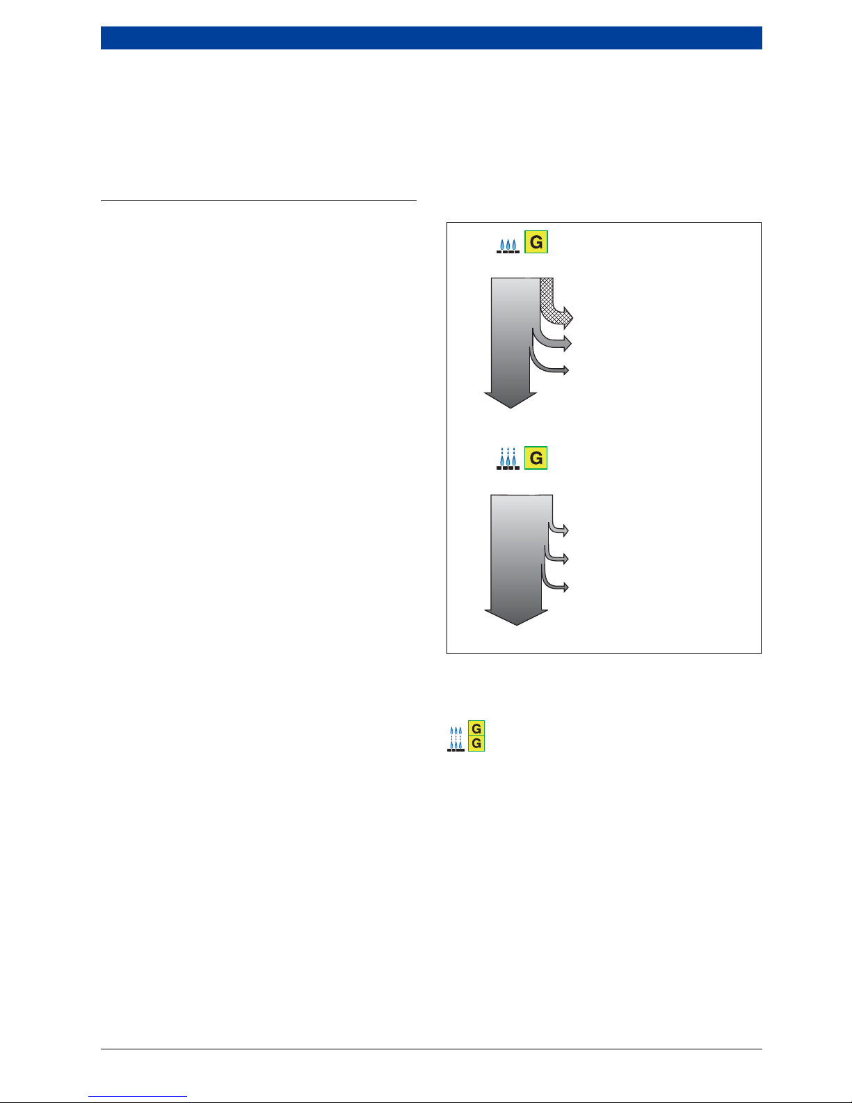
When comparing the energy utilisation of conventional
boilers and condensing boilers or boilers with
condensing heat exchangers, an energy statement such
as the example shown in Fig. 3 can result.
Condensation heat (latent heat)
• The proportion of condensation heat in natural gas is
approx. 11 %, relative to the net calorific value H
i
.
With low-sulphur fuel oil, the proportion of
condensation heat is approx. 7 %, relative to the net
calorific value H
i
.
This heat is unused in conventional boilers.
• By making use of the condensation in the water
vapour, the condensing boiler or boiler with
condensing heat exchanger enables considerable
utilisation of this heat potential.
Flue loss (sensible heat)
• With the conventional boiler, the heat in the flue gas,
which is at a relatively high temperature of 150 °C to
210 °C, escapes. This means an unused heat
proportion of around 6 % to 9 % is lost.
• The dramatic reduction of the flue gas temperatures
in a condensing boiler or boiler with condensing heat
exchanger down to 30 °C makes use of the sensible
heat in the hot gas and considerably reduces the flue
loss.
Energy statement comparing conventional boilers and
condensing boilers or boilers with condensing heat
exchangers
Fig. 3 Energy statement comparing conventional boilers
and condensing boilers or boilers with
condensing heat exchangers (example with
natural gas)
Conventional boiler
Condensing boiler or boiler with condensing
heat exchanger
η
K
Boiler efficiency
q
A
Flue losses (sensible heat)
q
L
Unused condensation heat (latent
heat)
q
S
Radiation losses
1)
Relative to net calorific value Hi= 100 %
qL = 11 %
q
A
= 5,9 %
q
S
= 0,1 %
q
L
= 1,5 %
q
A
= 1 %
q
S
= 0,5 %
6 720 642 347-75.1il
ηK = 94 %
111 %
1)
111 %
1)
ηK = 108 %
6 | Basic principles
UNIMAT6 720 807 794 (2013/04)
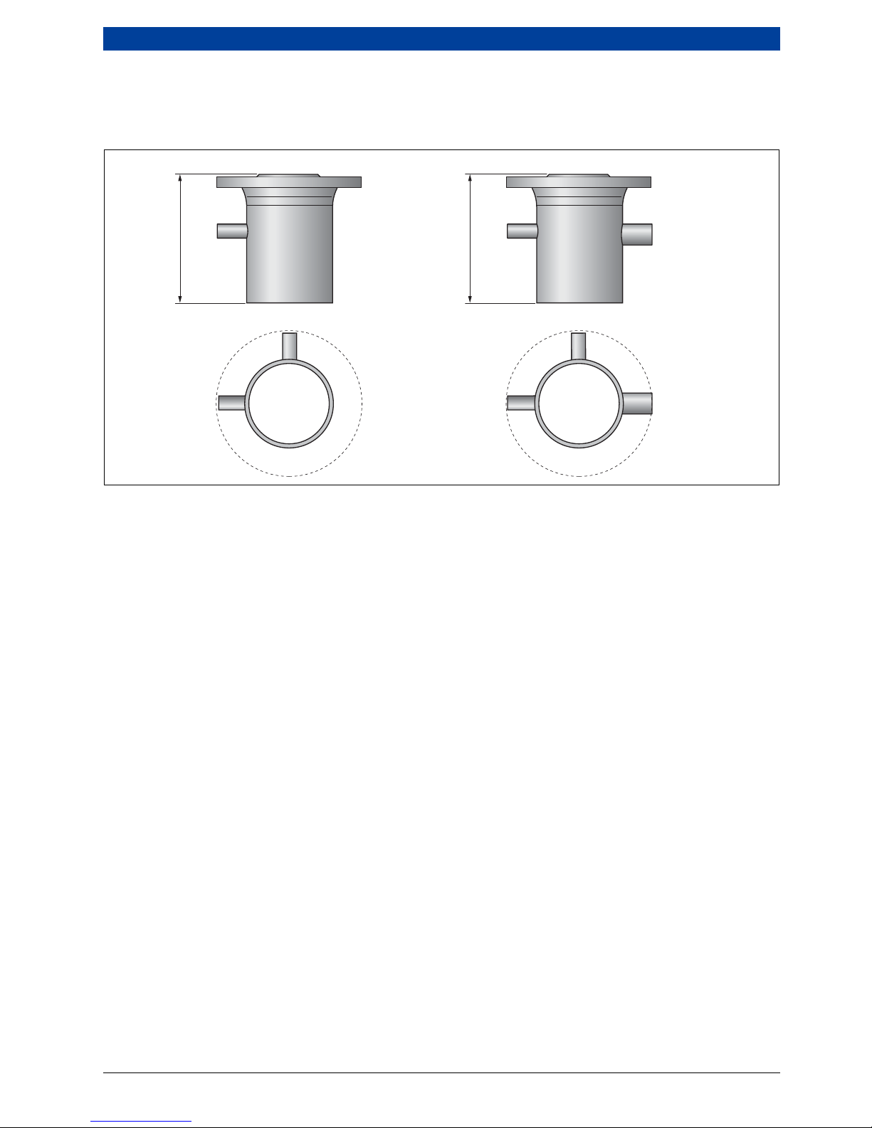
2.2 Making optimal use of condensing
technology
2.2.1 Matching to the heating system
Condensing boilers or boilers with condensing heat
exchangers can be installed in any heating system.
However, the available proportion of condensation heat
and the efficiency resulting from this type of operating
mode depend on the design of the heating system.
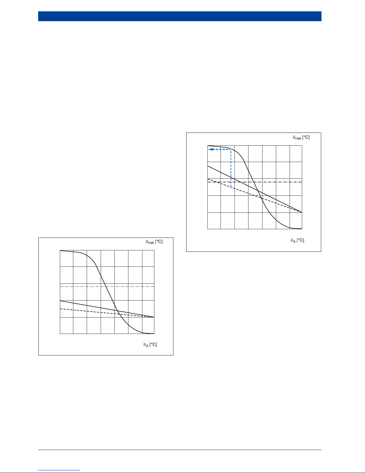
To be able to use the condensation heat of the water
vapour in the hot gas, the hot gas must be cooled to
below the dew point. The utilisation rate of the
condensation heat is therefore necessarily subject to the
system design temperatures and the hours run in the
condensation range. This is shown by the graphs in
Fig. 4 and Fig. 5. The dew point is approx. 56° C for
natural gas and approx. 47° C for low-sulphur fuel oil.
Heating system 40/30 °C
In this heating system, the benefits of the performance
capacity of condensing technology can be seen
throughout the heating season. The low return
temperatures are always below the dew point, so
condensation heat is always created ( Fig. 4). This is
achieved with low temperature area heaters or
underfloor heating systems, which are ideal for
condensing boilers or boilers with condensing heat
exchangers.
Targeted utilisation of the condensing effect is possible
with the condensing heat exchanger (ECO 6) connected
separately to a low temperature heating circuit.
Fig. 4 Condensation heat utilisation at 40/30 °C
(example with natural gas)
A Proportion of operation with condensation heat
utilisation
a Annual heat load curve
b Dew point temperature curve (example with
natural gas)
c System temperatures
ϑ
A
Outside temperature
ϑ
HW
Heating water temperature
WHaAnnual heat load
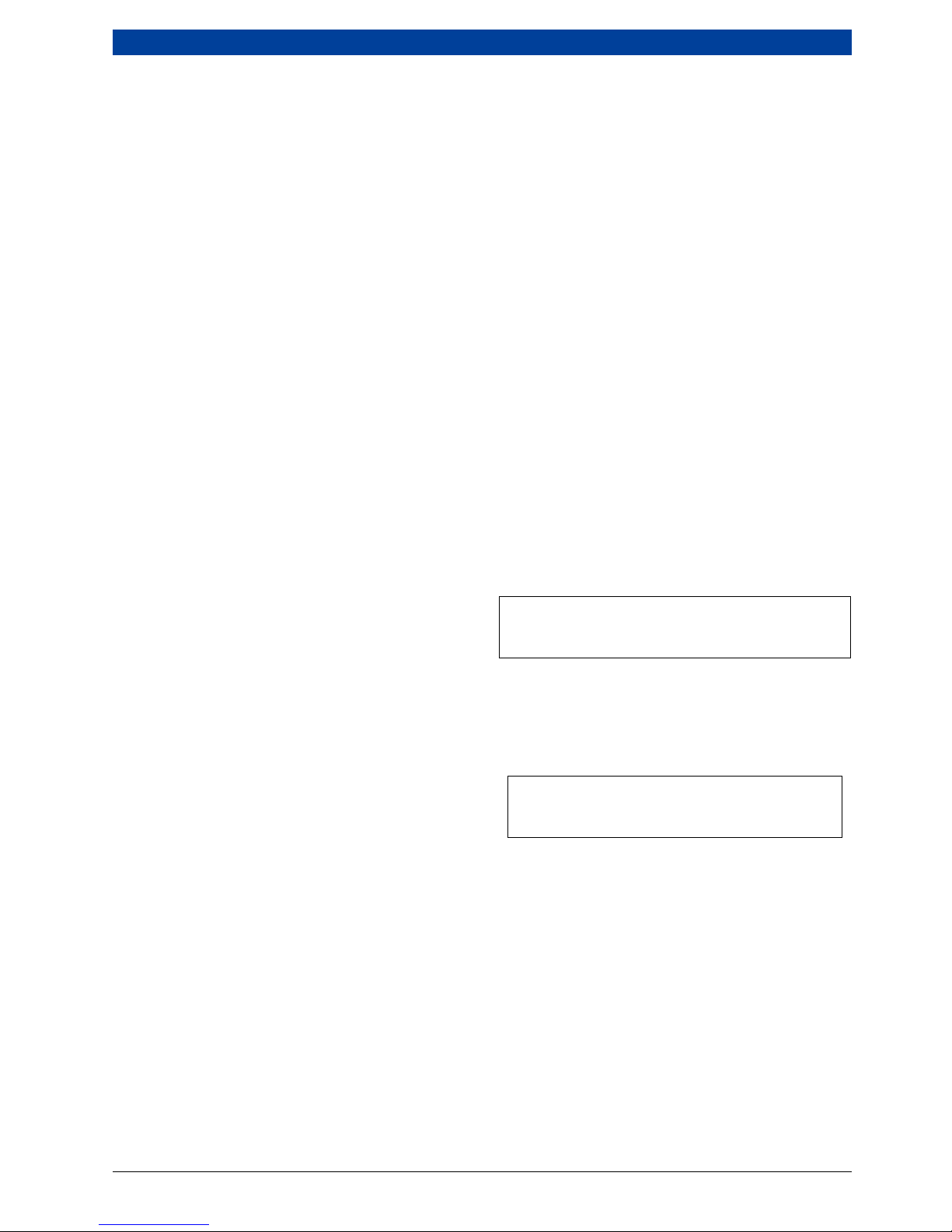
Heating system 75/60 °C
Even with a design temperature of 75/60 °C, it is
possible to make above average utilisation of the
condensation heat for around 95 % of the annual heat
load. This applies for outside temperatures of –7 °C to
+20 °C ( Fig. 5).
Due to the safety supplements in the former DIN 4701
from 1959, older heating systems designed with 90/
70 °C are nowadays to all intents and purposes operated
as systems with 75/60 °C. Even if these systems were
run with system temperatures of 90/70 °C and
modulating, weather-compensated heating circuit
temperatures, they would still use the condensation
heat for 80 % of the annual heating load.
Fig. 5 Condensation heat utilisation at 75/60 °C
(example with natural gas)
A Proportion of operation with condensation heat
utilisation
a Annual heat load curve
b Dew point temperature curve
c System temperatures
ϑ
A
Outside temperature
ϑ
HW
Heating water temperature
W
Ha
Annual heat load
WHa [%]
– 15 – 10 – 5 5 10
6 720 803 977-30.1itl
15 20± 0
100
80
60
40
20
0
100
80
60
40
20
0
56
a
b
c
A
– 15 – 10 – 5 5 10 15 20± 0
100
80
60
40
20
0
56
80
60
40
20
0
95
W
Ha
[%]
6 720 803 977-31.1itl
a
b
c
A
Basic principles | 7
6 720 807 794 (2013/04)UNIMAT
2.2.2 High standard seasonal efficiency [to DIN]
The graphs in Fig. 4 and Fig. 5 show that the varying
proportion of condensation heat utilisation has a direct
influence on the energy utilisation of the condensing
boiler or boiler with condensing heat exchanger.
The high standard seasonal efficiency [to DIN] of gas
condensing boilers is based on the following influences:
• Achievement of high CO
2
levels. The higher the CO2
content, the higher the dew point of the hot gases.
• Lower system and return temperatures can be
maintained. The lower the system and return
temperatures, the higher the condensation rate and
the lower the flue gas temperature.
The UNIMAT UT-L boilers can be matched individually
to the prevailing system characteristics and
requirements, subject to the individual project.
2.2.3 Design information
In new installations, every opportunity should be
exploited to achieve optimum operation of the
condensing boiler or boiler with condensing heat
exchanger.
A high standard seasonal efficiency [to DIN] is achieved
if the following criteria are satisfied:
• Limit the return temperature upstream of the
condensing heat exchanger to a maximum of 50 °C, at
least partially. In this connection, it is significant that
the separate connections for the boiler and
condensing heat exchanger mean a partial flow rate of
20 % with a low design temperature (e.g. 40/30 °C) is
sufficient to achieve excellent condensing efficiency.
• Aim for a temperature spread between the flow and
return of at least 20 K.
• Avoid installations for return temperature raising (e.g.
4-way mixers, bypass circuits, low loss headers,
depressurised distributors, etc.).
For more detailed information on the hydraulic
connection, see chapter 9 on page 47 ff.
2.3 Economic viability considerations
2.3.1 Simplified comparison of conventional boilers
and condensing boilers or boilers with
condensing heat exchangers
Fuel costs
•Given
– Building heat demand QN= 2000 kW
– Annual heating energy demand Q
A
=
3400000 kWh/a
– System design temperatures:
Ventilation ϑV/ϑR= 90/70 °C (proportion 20 %)
Radiators ϑV/ϑR= 75/60 °C (proportion 50 %)
Underfloor heating system ϑ
V/ϑR
= 40/30 °C
(proportion 30 %)
– Fuel costs K
B
=0.50Euro/m
3
– Conventional UNIMAT UT-L boiler, rated output
2000 kW, η
N
= 94,9 %
–UNIMATUT-L boiler with condensing heat
exchanger, rated output 2000 kW, η
N
= 102,3 %
The efficiency levels η
N
specified for the UNIMAT UT-L
boiler with condensing heat exchanger apply if the
underfloor heating systems are connected separately to
the condensing heat exchanger.
•Sought
– Fuel consumption
– Fuel costs
•Calculation
F. 1 Calculation of annual fuel consumption
B
V
Annual fuel consumption in m3/a
ηNStandard seasonal efficiency [to DIN] in %
H
i
Net calorific value; here natural gas simplified with
10 kWh/m
3
QANet heating energy demand in kWh/a
F. 2 Calculation of annual fuel costs
B
V
Annual fuel consumption in m3/a
KBFuel costs
KBaAnnual fuel costs
• Result
– UNIMAT UT-L boiler with rated output of 2000 kW:
Fuel consumption B
V
= 358272 m3/a,
Fuel costs KBa = 179136 Euro/a
– UNIMAT UT-L boiler with condensing heat
exchanger, with rated output of 2000 kW:
Fuel consumption BV = 332356 m3/a,
Fuel costs KBa = 166178 Euro/a
Central heating using the UNIMAT UT-L boiler with
condensing heat exchanger results in fuel cost savings of
approx. 11601 Euro per year.
B
V
Q
A
η
NHi
×
-----------------------
=
K
BaBVKB
×=
8 | Technical description
UNIMAT6 720 807 794 (2013/04)
Investment costs
The investment costs are based on the costs of a boiler
system. This includes the costs of the boiler, boiler
circuit control unit, pressure-jet burner and flue system,
as well as the costs of the safety equipment and return
flow temperature safeguard. The costs of the UNIMAT
UT-L boiler with condensing heat exchanger also include
the neutralisation of the condensate. Costs for
installation have not been taken into account.
Reflux of capital
In this example, the investment costs have been repaid
due to the lower fuel costs after about one year. It is
generally true that condensing technology pays for itself
faster the greater the output and the higher the fuel
costs. No subsidies have been taken into account in the
calculations. With the UNIMAT UT-L boilers, it is possible
to integrate further condensing heat exchangers. This
results in higher efficiency and therefore lower fuel
costs.
3 Technical description
3.1 UNIMAT UT-L boiler
3.1.1 Equipment overview
The UNIMAT UT-L boilers are oil/gas special boilers for
positive pressure combustion to EN 303. These boilers
are designed to produce low pressure hot water with no
more than 110 °C (shutdown temperature of the high
limit safety cut-out) for heating systems that correspond
to the demands of DIN-EN 12828. The permissible
overall pressure must not exceed the permissible
pressure stage of the boiler. The modular design of the
boiler and additional equipment enables universal
application.
• Round boiler casing made of textured aluminium
sheeting
• Visible parts of the boiler primed in anthracite grey
and red
• Thermal insulation (100 mm) and extremely well
insulated burner door
• Boiler pressure body with connections for flow,
return, safety valve and drain
• As an option with inspection port on the water side
• Bottom rear inspection aperture on flue gas collector
• Boiler base frame for even load distribution and easy
transportation
• Large burner door closing on the left hand side
(can be changed to the right hand side if required)
• Air-cooled combustion chamber sight glass
The following options are possible:
• Control unit holder
• Also available as a unit version (with boiler and
burner)
• Heat exchanger as integrated or stand-alone version
with and without the use of condensing technology
Scope of
investment
1)
1) Incl. accessories
Unit UNIMAT UT-L
boiler with a
rated output
of
2000 kW
UNIMAT UT-
L boiler with
condensing
heat
exchanger
with a rated
output of
2000 kW
Total
investment
costs
Euro 50000 63000
Table 2 Investment costs for conventional boilers and
boilers with condensing heat exchangers (values
rounded off)
Type of cost Unit
UNIMAT
UT-L boiler
with a rated
output of
2000 kW
UNIMAT UT-
L boiler with
condensing
heat
exchanger
with a rated
output of
2000 kW
Investment costs Euro 50000 63000
Costs linked to
capital
1)
1) Annuity 9,44 %, interest 5 %, maintenance 1 %
Euro/a 5220 6577
Fuel costs Euro/a 179136 166178
Total costs Euro/a 184356 172755
Table 3 Total costs for conventional boilers and boilers
with condensing heat exchangers (values rounded
off)
Technical description | 9
6 720 807 794 (2013/04)UNIMAT
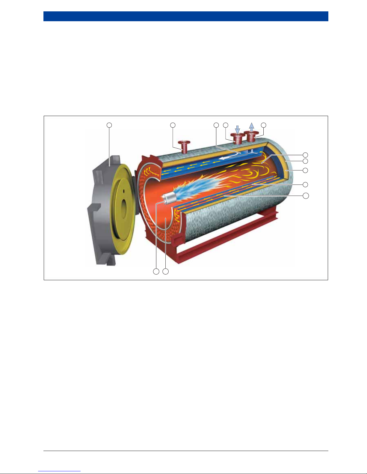
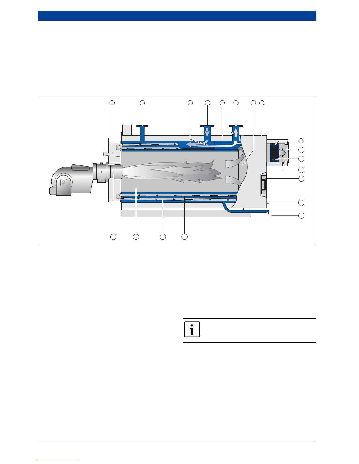
3.1.2 Function principle
Boiler technology
All UNIMAT UT-L boilers boilers have a water guide
element installed below the return connector. With this,
the return water generates an injector effect through its
velocity as it flows back, so hotter boiler water is added
and mixes with the cooler return water. The targeted
feed of the return water results in excellent flow across
the entire boiler cross-section. Due to the flat
temperature slope in the boiler block, the boiler overall
provides an extremely even temperature distribution.
The flow through the boiler results in condensation-free
and safe heating operation with a minimum return
temperature as low as 50 °C.
The boiler is built using the 3-pass design and the
countercurrent heat exchanger principle. Together with
an effective heating surface design, these are the
prerequisites for low emissions and high energy
efficiency. Subject to the system, the UNIMAT UT-L
boilers achieve very high standard seasonal efficiency
[to DIN], which can be increased to up to 106 % with the
boiler with condensing heat exchanger.
Fig. 6 Sectional view showing the function principle of the UNIMAT UT-L boiler
[1] Burner door
[2] Safety valve connector ( Fig. 51, page 73)
[3] Water guide system
[4] Return ( Fig. 50, page 72 and Fig. 53, page 76)
[5] Flow ( Fig. 49, page 71)
[6] Hot gas reversing chamber
[7] Protective aluminium casing
[8] High grade insulation without thermal bridges
[9] First secondary heating surface (second pass)
designed as a double row
[10] Second secondary heating surface (third pass)
[11] Combustion chamber (first pass)
[12] Blast tube
1
2
12 11
45
3
10
9
8
7
6
6 720 803 977-01.1ITL
10 | Technical description
UNIMAT6 720 807 794 (2013/04)
3.2 UNIMAT UT-L boiler
3.2.1 Version overview
The conventional UNIMAT UT-L boiler can be fitted with
a flue gas heat exchanger to increase efficiency and
reduce the fuel required. The flue gas heat exchanger
can be supplied as an integrated version (integrated in
the flue gas collector chamber) or as a stand-alone
version (for installation downstream of the boiler). You
can choose between a galvanised steel version of the
heat exchanger bundle (ECO 7; without the use of
condensing technology) and a version of the heat
exchanger bundle in stainless steel (ECO 6; with the use
of condensing technology). The heat exchanger is
generally designed for modular construction. This means
the most suitably sized heat exchanger, or number
thereof, for the project in question can be chosen on an
individual basis.
Fig. 7 Function principle of the UNIMAT UT-L boiler with flue gas heat exchanger
[1] Burner door
[2] Safety valve connector ( Fig. 51, page 73)
[3] Water guide system
[4] Return ( Fig. 50, page 72 and Fig. 53, page 76)
[5] High grade insulation without thermal bridges
[6] Flow ( Fig. 49, page 71)
[7] Hot gas reversing chamber
[8] Protective aluminium casing
[9] Heat exchanger flow
[10] Heat exchanger
[11] Heat exchanger return
[12] Condensate connector
[13] inspection aperture
[14] Drain connection ( Fig. 56, page 79)
[15] First secondary heating surface (second pass)
designed as a double row
[16] Second secondary heating surface (third pass)
[17] Combustion chamber (first pass)
[18] Blast tube
43
8
67
521
9
10
12
13
11
12
14
15
16
1718
6 720 642 347-04.1il
Inspection aperture on the water side is
optional.

Technical description | 11
6 720 807 794 (2013/04)UNIMAT
3.2.2 Function principle
In the flue gas heat exchanger, heat is recovered from
the hotter boiler flue gas by channelling cooler mains
return water through the heat exchanger pipe to reduce
the flue gas temperature. The energy gained in this way
gives a higher boiler efficiency and therefore lower fuel
consumption and lower flue gas emissions.
With the fuels gas and low sulphur fuel oil, aim for as low
a water inlet temperature as possible at the flue gas heat
exchanger. This deliberately creates operation with
condensate (flue gas condensation), so that even higher
efficiency can be achieved.
If the flue gas heat exchanger is operated with fuel oil
(not low sulphur quality), ensure a corresponding
minimum water inlet temperature at the flue gas heat
exchanger of 60 °C to protect it from corrosion on the
flue gas side. With oil operation, an optional control on
the water side can be used to raise the water inlet
temperature at the flue gas heat exchanger to the
required minimum level by mixing in pre-heated water.
With oil operation, for flue gas heat exchangers with an
integral flue gas bypass, if the water inlet temperature
cannot be raised to the minimum level, the entire flue
gas flow from the boiler bypasses the flue gas heat
exchanger, using the flue gas control valve. A flue gas
temperature control unit is available as an option for an
additional charge.
12 | Technical description
UNIMAT6 720 807 794 (2013/04)
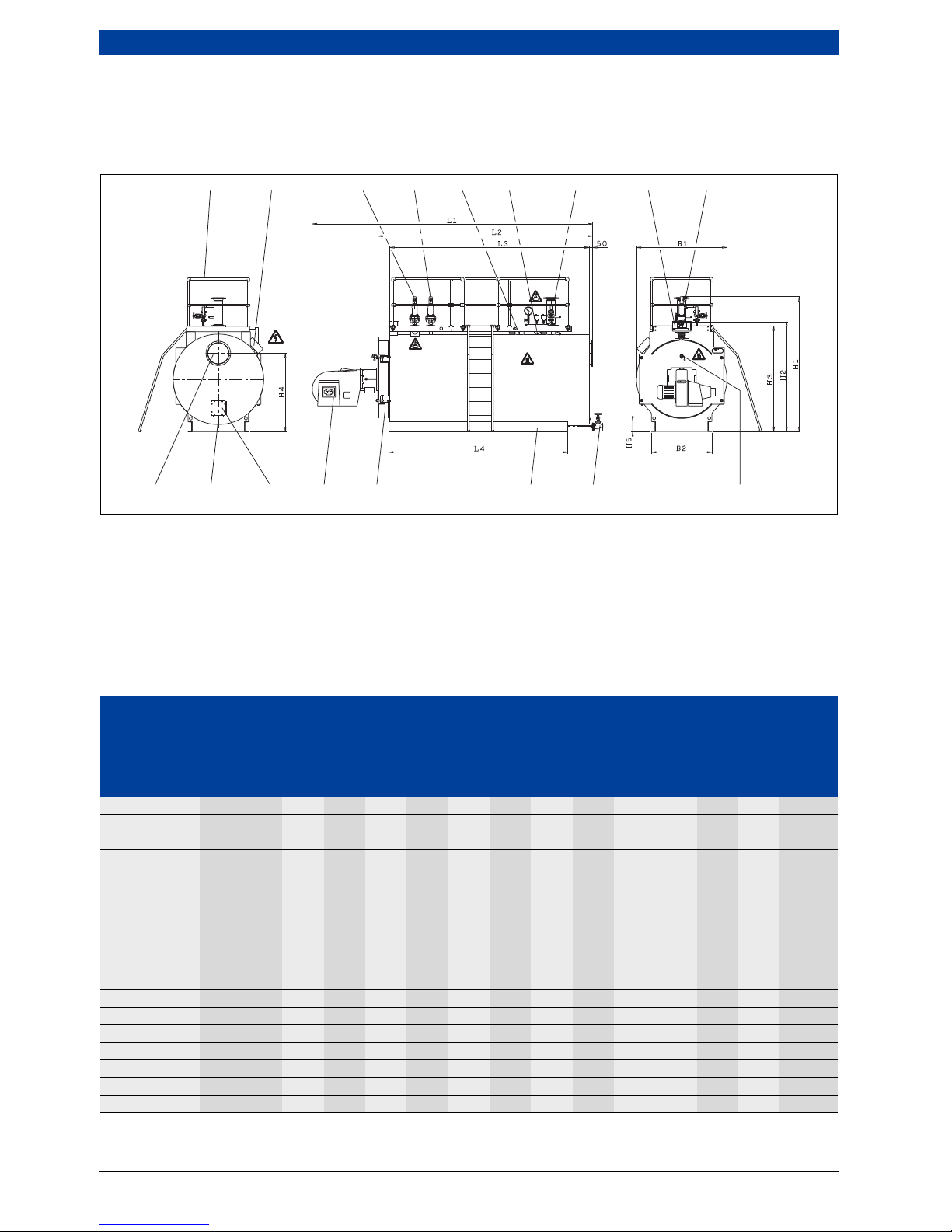
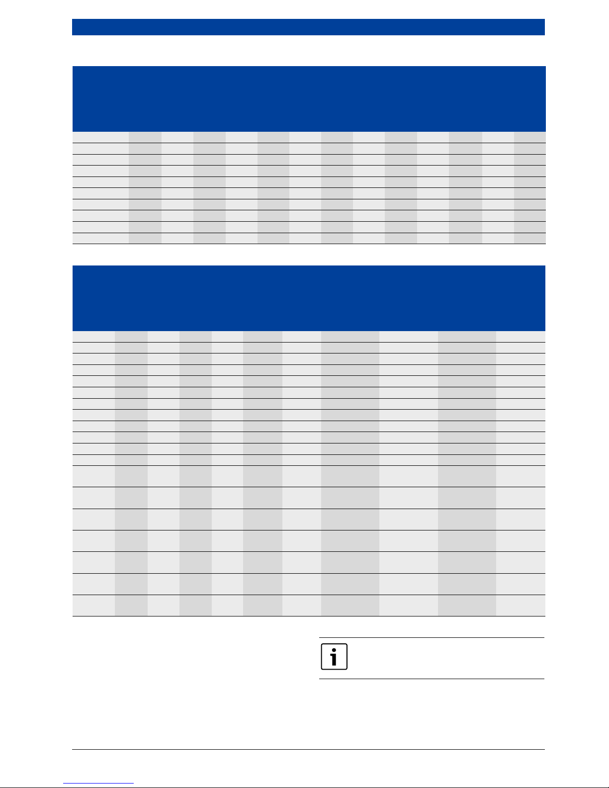
3.3 Dimensions and specification for the flue
gas heat exchangers
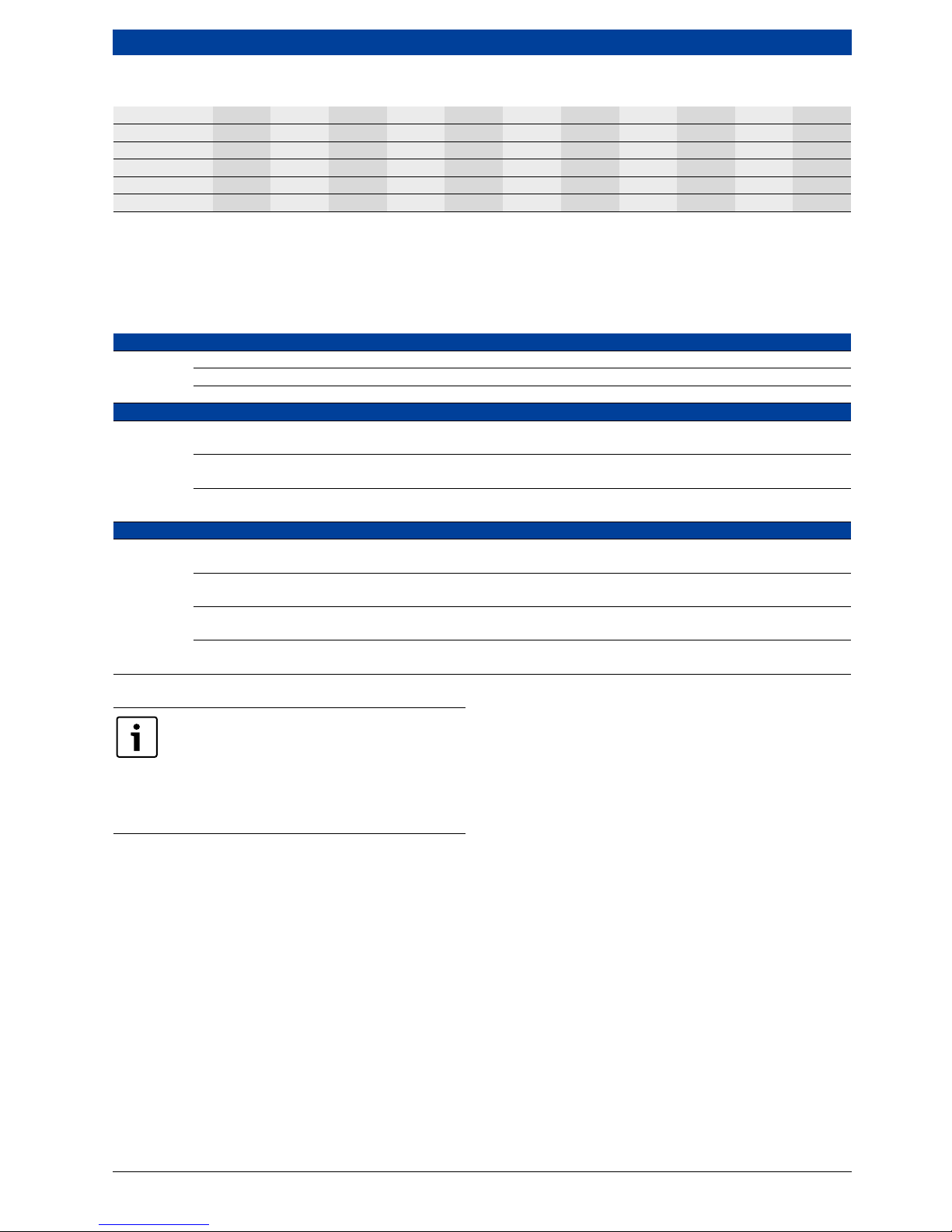
3.3.1 UNIMAT UT-L boiler
Fig. 8 UNIMAT UT-L boiler
51.002 Optional instrument housing
51.004 Optional terminal box
A01.000 Optional burner
D03.000 Flue gas connecting branch
D04.000 Boiler front door
D05.002 Inspection aperture on the flue gas side
D05.005 Flame inspection hole
D06.000 Base frame
D06.002 Lifting lug
D07.000 Optional maintenance platform
D08.000 Optional positive pressure safety valve 1
D08.100 Optional positive pressure safety valve 2
D10.000 Flow
D10.002 Optional intermediate flow piece
D11.000 Return
D12.001 Optional outlet shut-off valve
D12.503 Connection for flue gas condensate drainage
system
6 720 803 977-11.1itl
D07.000
D03.000 D12.503 D05.002 A01.000 D04.000 D06.000 D12.001 D05.005
51.004 D08.100 D11.000D08.000 D06.002 D10.000 51.002 D10.002
UNIMAT
UT-L boiler
Output limit Dimension(s)
Flue gas
connection
Base frame
L1
1)
L2 L3 B1 H12)H2 H33)H4 L4 B2
H5
Channel
section
Type kW [mm] [mm] [mm] [mm] [mm] [mm] [mm] [mm] [mm] [mm] [mm] [mm]
UT-L 1 650 3135 2295 2040 1174 2152 1540 1460 1055 1750 710 120 1055
UT-L 2 750 3516 2680 2425 1324 2302 1695 1610 1180 2100 910 120 1180
UT-L 4 1000 3516 2680 2425 1324 2302 1695 1610 1180 2100 910 120 1180
UT-L 6 1000 3786 2950 2695 1424 2402 1795 1710 1240 2350 910 120 1240
UT-L 8 1250 4056 3220 2960 1524 2502 1895 1810 1340 2560 930 160 1340
UT-L 10 1350 3778 2950 2695 1424 2402 1795 1710 1240 2350 910 120 1240
UT-L 12 1500 4503 3675 3420 1574 2552 1950 1860 1350 3060 1130 160 1350
UT-L 14 1900 4092 3220 2960 1524 2502 1895 1810 1340 2560 930 160 1340
UT-L 16 2000 4597 3725 3465 1674 2652 2050 1960 1415 3060 1130 160 1415
UT-L 18 2500 4654 3675 3420 1574 2552 1950 1860 1350 3060 1130 160 1350
UT-L 20 2500 5054 4075 3820 1724 2702 2100 2010 1490 3410 1150 200 1490
UT-L 22 3000 5895 4570 4250 1824 2817 2200 2110 1500 3920 1260 220 1500
UT-L 24 3050 4916 3725 3465 1674 2667 2050 1960 1415 3060 1130 160 1415
UT-L 26 3500 6025 4700 4380 1924 2917 2300 2210 1600 3920 1510 220 1600
UT-L 28 3700 5266 4075 3820 1724 2717 2100 2010 1490 3410 1150 200 1490
UT-L 30 4200 5761 4570 4250 1824 2817 2200 2110 1500 3920 1260 220 1500
UT-L 32 4250 6419 5090 4770 2124 3117 2505 2410 1750 4280 1510 220 1750
UT-L 34 5200 6385 4700 4380 1924 3007 2300 2210 1600 3920 1510 220 1600
Table 4 Main dimensions

Technical description | 13
6 720 807 794 (2013/04)UNIMAT
• For information and instructions regarding the
requirements for the boiler installation room, see
chapter 10.2, page 67.
• Equipment and complete dimensions according to
project-specific technical datasheet
• Dimensions given with ± 1 % tolerance
• These dimensions are designed for standard
insulation:
– 100-mm thick on back floor
– 100-mm thick on casing
• Sizing for the entrance:
– Transport height: additional clearance of at least
100 mm from dimension H1 or dimension H2
(valves fitted/not fitted)
– Minimum door clearance: additional clearance of at
least 200 mm from dimension B1 (valves fitted/not
fitted)
• The height of the boiler room is determined by the
system equipment. The clearance above the
maintenance platform should be at least 2 m.
UT-L 36 5250 6655 5320 5000 2274 3357 2655 2560 1850 4480 1520 240 1850
UT-L 38
4)
6000 6855 5520 5200 2424 3507 - 2710 2000 4650 1610 240 2000
UT-L 40 6500 6775 5090 4770 2124 3207 2505 2410 1750 4280 1510 220 1750
UT-L 42 7700 7235 5320 5000 2274 3462 2655 2560 1850 4480 1520 240 1850
UT-L 44
4)
8000 7683 5980 5655 2574 3762 - 2875 2100 5050 1630 280 2100
UT-L 46
4)
9300 7435 5520 5200 2424 3612 - 2710 2000 4650 1610 240 2000
UT-L 48
4)
10000 8285 6315 5990 2724 3912 - 3010 2200 5320 1890 280 2200
UT-L 50
4)
11200 8121 5980 5655 2574 3947 - 2875 2100 5050 1630 280 2100
UT-L 52
4)
12000 9086 7050 6725 2924 4297 - 3239 2440 6000 1890 280 2440
UT-L 54
4)
12600 7162 6315 5990 2724 4097 - 3010 2200 5320 1890 280 2200
UT-L 56
4)
14000 8803 7530 7170 3224 4597 - 3542 2600 6390 2100 320 2600
UT-L 58
4)
14700 9086 7050 6725 2924 4377 - 3239 2440 6000 1890 280 2440
UT-L 60
4)
16400 9566 7530 7170 3224 4677 - 3542 2600 6390 2100 320 2600
UT-L 62
4)
17500 9227 7980 7620 3424 4877 - 3770 2820 6790 2100 320 2820
UT-L 64
4)
19200 9227 7980 7620 3424 4877 - 3770 2820 6790 2100 320 2820
1) The dimension L1 is a recommended dimension and is subject to the burner manufacturer, type and the actual output. If a flue gas heat
exchanger is included in the standard delivery, the corresponding dimension of length in accordance with datasheet DA170/DA171
must be taken into account.
2) Minimum transport dimensions when valves, burner and terminal box have been removed (without cable conduit; with cable conduit +
75 mm on the right).
3) Maximum dimension above boiler connector, lifting lug or door mounting.
4) UNIMATIC positioned at the side.
UNIMAT
UT-L boiler
Output limit Dimension(s)
Flue gas
connection
Base frame
L1
1)
L2 L3 B1 H12)H2 H33)H4 L4 B2
H5
Channel
section
Type kW [mm] [mm] [mm] [mm] [mm] [mm] [mm] [mm] [mm] [mm] [mm] [mm]
Table 4 Main dimensions
14 | Technical description
UNIMAT6 720 807 794 (2013/04)
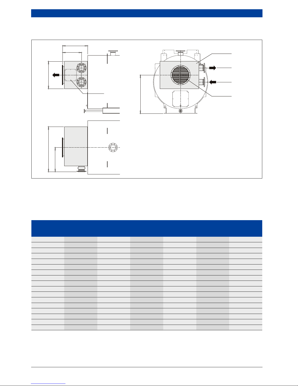
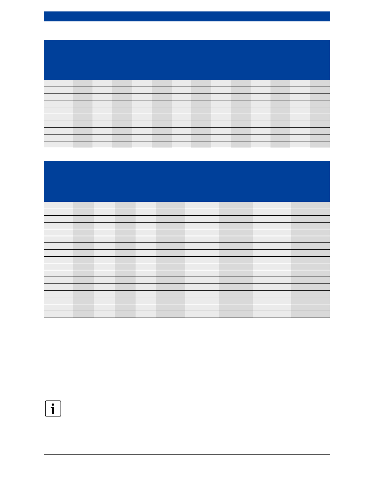
3.3.2 Integrated heat exchanger without condensing technology — ECO 7
Fig. 9 Integrated heat exchanger without condensing technology — ECO 7
W32.000 Flue gas heat exchanger
W32.510 Connection for water outlet
W32.008 Inspection aperture on the flue gas side
W32.509 Connection for water inlet
D03.000 Flue gas connecting branch
1)
If the heat exchanger is designed to have several
bundle elements, the dimensions increase by
300 mm per bundle.
2)
For heat exchangers having a water inlet/water
outlet with an internal diameter of DN150, the
dimensions increase by 50 mm.
740
1)
2)
560
W32.509
W32.000
D03.000
W32.510
H2
H1
B1
B2
W32.008
6 720 803 977-10.1itl
Heat exchanger
Shipping weight Water capacity Measurements
1 bundle 2 bundle B 1
2)
B 2 H 2
ECO 7 [~kg] [~kg] [l] [mm] [mm] [mm]
390/245 90 140 10 809 490 459
510/325 110 180 15 929 550 539
600/378 140 220 20 1019 595 592
690/432 160 260 26 1109 640 646
750/485 190 310 29 1169 670 699
890/592 230 370 37 1309 740 806
930/618 250 400 42 1349 760 832
1000/672 280 440 46 1419 795 886
1110/752 300 480 52 1529 850 966
1300/885 350 550 64 1719 945 1099
1350/965 420 670 85 1769 970 1179
1550/1045 480 780 98 1969 1070 1259
1600/1072 540 890 119 2019 1095 1286
1750/1178 600 980 125 2169 1170 1392
1900/1258 660 1060 148 2319 1245 1472
2050/1365 760 1240 173 2469 1320 1579
2200/1472 850 1390 200 2619 1395 1686
Table 5 Main dimensions

Technical description | 15
6 720 807 794 (2013/04)UNIMAT
• For information and instructions regarding the
requirements for the boiler installation room, see
chapter 10.2, page 67.
• These dimensions are designed for 100-mm thick
insulation.
• Connections W32.509 and W32.510 can be made on
the right hand or left hand side.
• Dimensions given with ± 1 % tolerance; weights given
with ± 3 % tolerance.
UNIMAT UT-L UT-L 1 UT-L 2 UT-L 4 UT-L 6 UT-L 8 UT-L 10 UT-L 12 UT-L 14 UT-L 16 UT-L 18 UT-L 20
H1 [mm] 950 1060 1060 1050 1150 1050 1205 1150 1215 1205 1240
UNIMAT UT-L UT-L 22 UT-L 24 UT-L 26 UT-L 28 UT-L 30 UT-L 32 UT-L 34 UT-L 36 UT-L 38 UT-L 40 UT-L 42
H1 [mm] 1260 1215 1330 1240 1260 1360 1330 1495 1550 1360 1495
UNIMAT UT-L UT-L 44 UT-L 46 UT-L 48 UT-L 50 UT-L 52 UT-L 54 UT-L 56 UT-L 58 UT-L 60 UT-L 62 UT-L 64
H1 [mm] 1705 1550 1750 1705 1900 1750 2030 1900 2030 2150 2150
Table 6 Dimension H1 depends on the boiler size
UNIMAT UT-L UT-L 1 UT-L 2 UT-L 4 UT-L 6 UT-L 8 UT-L 10 UT-L 12 UT-L 14 UT-L 16 UT-L 18 UT-L 20
ECO 7 heat
exchanger
510/325 510/325 510/325 510/325 600/378 600/378 600/378 690/432 690/432 750/485 750/485
390/245 510/325 600/378 690/432
600/378
UNIMAT UT-L UT-L 22 UT-L 24 UT-L 26 UT-L 28 UT-L 30 UT-L 32 UT-L 34 UT-L 36 UT-L 38 UT-L 40 UT-L 42
ECO 7 heat
exchanger
890/592 890/592 930/618 930/618
1000/
672
1000/
672
1110/
752
1110/
752
1300/
885
1300/
885
1350/
985
750/485 890/592 930/618
1000/
672
1110/
752
1110/
752
1300/
885
690/432 750/485 890/592 930/618
1000/
672
1110/
752
UNIMAT UT-L UT-L 44 UT-L 46 UT-L 48 UT-L 50 UT-L 52 UT-L 54 UT-L 56 UT-L 58 UT-L 60 UT-L 62 UT-L 64
ECO 7 heat
exchanger
1350/
965
1550/
1045
1550/
1045
1600/
1072
1600/
1072
1750/
1178
1750/
1178
1900/
1258
2050/
1365
2050/
1365
2200/
1472
1300/
885
1350/
965
1550/
1045
1600/
1072
1600/
1072
1750/
1178
1900/
1258
1900/
1258
2050/
1365
1300/
885
1350/
965
1550/
1045
1600/
1072
1750/
1185
1900/
1258
1110/
752
1300/
885
1600/
1085
Table 7 Assignment of heat exchanger ECO 7 to boiler size
The tube bundles highlighted in bold
correspond to the assignment for the limit
output of the UNIMAT UT-L.
If the boiler is operated with low heating
output, a smaller flue gas heat exchanger
can also be selected under certain
circumstances.
16 | Technical description
UNIMAT6 720 807 794 (2013/04)
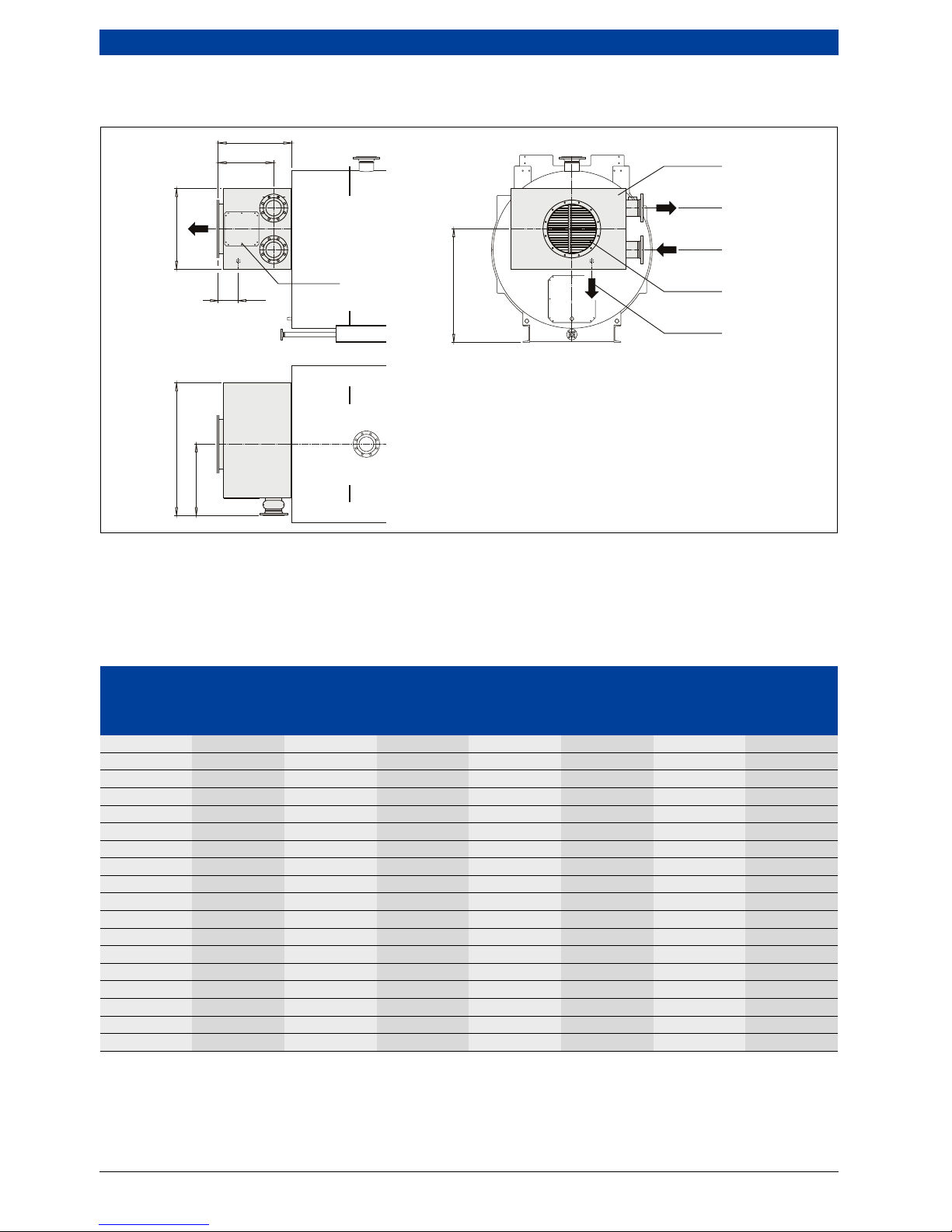
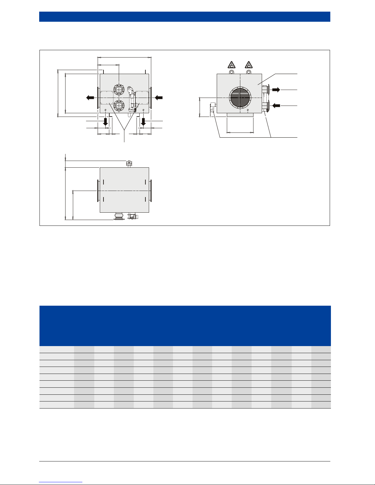
3.3.3 Integrated heat exchanger with condensing technology — ECO6
Fig. 10 Integrated heat exchanger with condensing technology — ECO 6
D03.000 Flue gas connecting branch
W32.000 Flue gas heat exchanger
W32.008 Inspection aperture on the flue gas side
W32.507 Connection for flue gas condensate
W32.509 Connection for water inlet
W32.510 Connection for water outlet
1)
If the heat exchanger is designed to have several
bundle elements, the dimensions increase by
300 mm per bundle.
2)
For heat exchangers having a water inlet/water
outlet with an internal diameter of DN150, the
dimensions increase by 50 mm.
740
1)
2)
560
200
W32.509
W32.000
W32.507
D03.000
W32.510
H2
H
1
B1
B2
W32.008
6 720 803 977-12.1itl
Heat
exchanger
Shipping weight Measurements Port
1 bundle 2 bundle
Water
capacity
B 1 B 2
2)
H 2 W32.506
ECO 6 [~kg] [~kg] [mm] [mm] [mm] [mm] [DN]
390 / 260 90 140 10 794 475 474 1"
510 / 335 110 180 15 914 535 549 1"
600 / 385 140 220 20 1004 580 599 1"
690 / 460 170 260 26 1094 625 674 1"
750 / 485 190 310 29 1154 655 699 1"
850 / 560 230 360 37 1254 705 774 1"
890 / 610 250 400 42 1294 725 824 1"
930 / 635 270 440 46 1334 745 849 1"
1000 / 685 290 470 52 1404 780 899 2"
1110 / 760 320 520 64 1514 835 974 2"
1300 / 885 400 650 85 1704 930 1099 2"
1350 / 985 460 750 98 1754 955 1199 2"
1550 / 1060 540 880 119 1954 1055 1274 2"
1600 / 1085 570 950 125 2004 1080 1299 2"
1750 / 1185 630 1040 148 2154 1155 1399 2"
1900 / 1285 730 1210 173 2304 1230 1499 2"
2050 / 1385 820 1360 200 2454 1305 1599 2"
2200 / 1485 930 1550 228 2604 1380 1699 2"
Table 8 Main dimensions
Technical description | 17
6 720 807 794 (2013/04)UNIMAT
• For information and instructions regarding the
requirements for the boiler installation room, see
chapter 10.2, page 67.
• These dimensions are designed for 100-mm thick
insulation.
• Connections W32.509 and W32.510 can be made on
the right hand or left hand side.
• Dimensions given with ± 1 % tolerance; weights given
with ± 3 % tolerance.
• Pipe thread to DIN 2999.
UNIMAT UT-L UT-L 2 UT-L 4 UT-L 6 UT-L 8 UT-L 10 UT-L 12 UT-L 14 UT-L 16 UT-L 18 UT-L 20 UT-L 22
H1 [mm] 1060 1060 1050 1150 1050 1205 1150 1215 1205 1240 1260
UNIMAT UT-L UT-L 24 UT-L 26 UT-L 28 UT-L 30 UT-L 32 UT-L 34 UT-L 36 UT-L 38 UT-L 40 UT-L 42 UT-L 44
H1 [mm] 1215 1330 1240 1260 1360 1330 1495 1550 1360 1495 1705
UNIMAT UT-L UT-L 46 UT-L 48 UT-L 50 UT-L 52 UT-L 54 UT-L 56 UT-L 58 UT-L 60 UT-L 62 UT-L 64
H1 [mm] 1550 1750 1705 1900 1750 2030 1900 2030 2150 2150
Table 9 Dimension H1 depends on the boiler size
UNIMAT UT-L UT-L 1 UT-L 2 UT-L 4 UT-L 6 UT-L 8 UT-L 10 UT-L 12 UT-L 14 UT-L 16 UT-L 18 UT-L 20
ECO 6 heat
exchanger
510/335 510/335 600/385 600/385 690/460 690/460 690/460 750/485 750/485 850/560 890/610
390/260 510/335 510/335 600/385 600/385 690/460 750/485 850/560
510/335 600/385 690/460
UNIMAT UT-L UT-L 22 UT-L 24 UT-L 26 UT-L 28 UT-L 30 UT-L 32 UT-L 34 UT-L 36 UT-L 38 UT-L 40 UT-L 42
ECO 6 heat
exchanger
890/610 890/610 930/635 930/635
1000/
685
1000/
685
1110/
760
1110/
760
1300/
885
1300/
885
1350/
985
850/560 890/610 930/635
1000/
685
1110/
760
1110/
760
1300/
885
750/485 890/610 890/610 930/635
1000/
685
1110/
760
UNIMAT UT-L UT-L 44 UT-L 46 UT-L 48 UT-L 50 UT-L 52 UT-L 54 UT-L 56 UT-L 58 UT-L 60 UT-L 62 UT-L 64
ECO 6 heat
exchanger
1350/
985
1550/
1060
1550/
1060
1600/
1085
1600/
1085
1750/
1185
1750/
1185
1900/
1285
2050/
1385
2050/
1385
2200/
1485
1300/
885
1350/
985
1550/
1060
1600/
1085
1600/
1085
1750/
1185
1900/
1285
1900/
1285
2050/
1385
1300/
885
1350/
985
1550/
1060
1600/
1085
1750/
1185
1900/
1285
1110/
760
1300/
885
1600/
1085
Table 10 Assignment of heat exchanger ECO 6 to boiler size
The tube bundles highlighted in bold
correspond to the assignment for the limit
output of the UNIMAT UT-L.
If the boiler is operated with low heating
output, a smaller flue gas heat exchanger
can also be selected under certain
circumstances.
18 | Technical description
UNIMAT6 720 807 794 (2013/04)
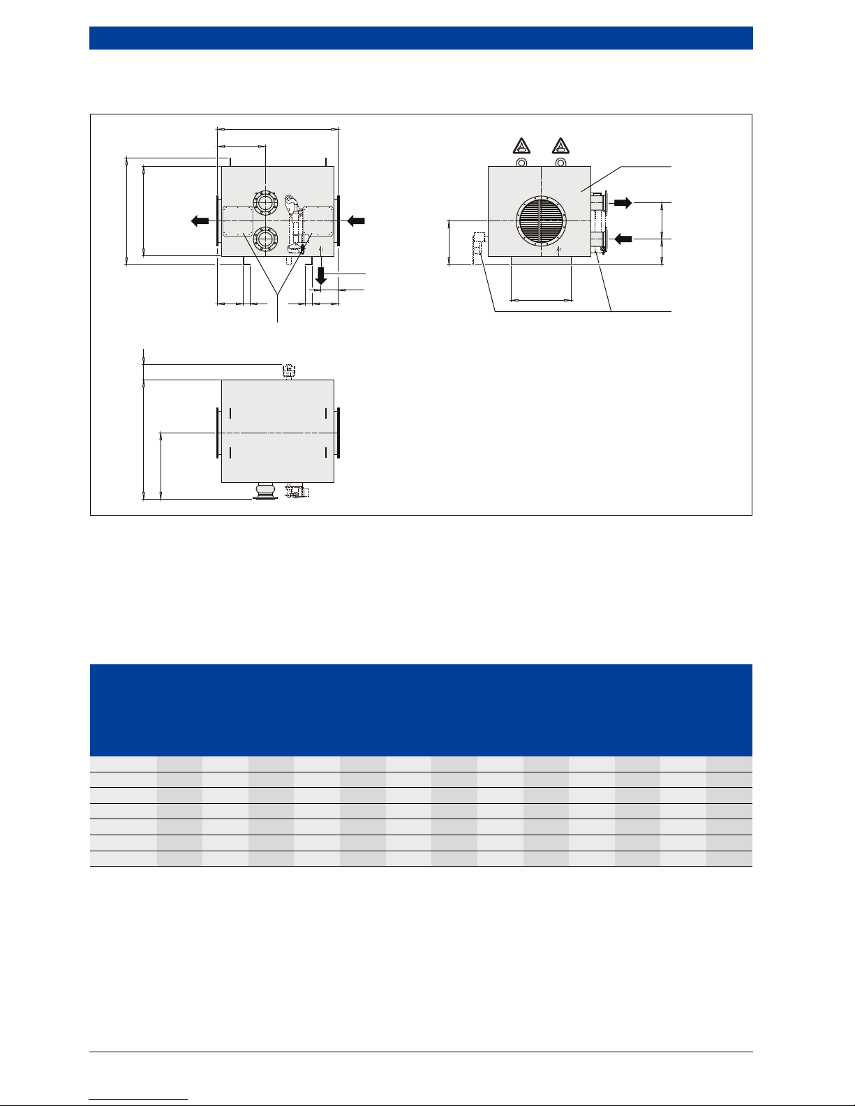
3.3.4 Stand-alone flue gas heat exchanger without condensing technology — ECO 7
Fig. 11 Stand-alone flue gas heat exchanger without condensing technology – ECO 7
W32.000 Flue gas heat exchanger
W32.002 Optional flue gas control valve
W32.008 Inspection aperture on the flue gas side
W32.506 Connection for drainage system
W32.509 Connection for water inlet
W32.510 Connection for water outlet
W32.540 Connection for flue gas inlet
W32.541 Connection for flue outlet
1)
If the heat exchanger is designed to have several
bundle elements, the dimensions increase by 300
mm per bundle.
2)
For heat exchangers having a water inlet/water
outlet with an internal diameter of DN150, the
dimensions increase by 50 mm.
B1 B4
B2
L 1
L 2
200
L 3 8 0 L 480
H3H4
H5
W32.509
W32.000
W32.002
W32.008
W32.510
H2
H1
W32.540
W32.506
B 3
W32.541
0-90°
0-90°
6 720 803 977-13.1itl
Heat
exchanger
Measurements
L 1
1)
L 2
1)
B 1
2)
B 2 B 3 B 4 H 1 H 2 H 3
without
bypass
with
bypass
without
bypass
with
bypass
without
bypass
with
bypass
without
bypass
with
bypass
ECO 7 [mm] [mm] [mm] [mm] [mm] [mm] [mm] [mm] [mm] [mm] [mm] [mm] [mm]
390 / 245 1120 1235 560 600 809 490 300 0 859 1002 459 602 534
510 / 325 1120 1310 560 600 929 550 400 0 939 1117 539 717 572
600 / 378 1120 1360 560 600 1019 595 500 0 892 1060 592 760 497
690 / 432 1120 1435 560 600 1109 640 500 0 846 1072 646 872 434
750 / 485 1120 1460 560 600 1169 670 600 0 899 1097 699 897 447
890 / 592 1120 1623 560 638 1309 740 750 0 1006 1247 806 1047 509
930 / 618 1120 1648 560 638 1349 760 750 0 1032 1272 832 1072 522
Table 11 Main dimensions
Technical description | 19
6 720 807 794 (2013/04)UNIMAT
• For information and instructions regarding the
requirements for the boiler installation room, see
chapter 10.2, page 67.
• These dimensions are designed for 100-mm thick
insulation.
• Connections W32.509 and W32.510 can be made on
the right hand or left hand side.
• Dimensions given with ± 1 % tolerance; weights given
with ± 3 % tolerance.
• Pipe thread to DIN 2999.
1000 / 672 1520 1840 760 780 1419 795 750 0 1086 1417 886 1217 547
1110 / 752 1520 1885 760 750 1529 850 900 0 1166 1472 966 1272 584
1300 / 885 1520 2025 760 765 1719 945 1100 0 1299 1607 1099 1407 647
1350 / 965 1520 2215 760 855 1769 970 1100 0 1379 1767 1179 1567 697
1550 / 1045 1520 2260 760 825 1969 1070 1350 0 1459 1832 1259 1632 734
1600 / 1072 1520 2230 760 900 2019 1095 1350 250 1486 1897 1286 1697 747
1750 / 1178 1920 2330 960 930 2169 1170 1550 250 1592 2017 1392 1817 797
1900 / 1258 1920 2270 960 930 2319 1245 1700 250 1672 2117 1472 1917 847
2050 / 1365 1920 2390 960 975 2469 1320 1700 250 1779 2247 1579 2047 897
2200 / 1472 1920 2470 960 1005 2619 1395 2000 250 1886 2367 1686 2167 947
Heat
exchanger
Measurements
Port Shipping weight
Water capacity
per bundle
L 3 L4 additional
weight with
bypass
W32.506 1 bundle 2 bundle
ECO 7 [mm] [mm] [mm] [DN] [~kg] [~kg] [~kg] [l]
390 / 245 353 380 353 285 1" 100 150 20 10
510 / 325 353 380 353 360 1" 130 200 40 15
600 / 378 353 380 353 410 1" 160 240 60 20
690 / 432 353 380 353 485 1" 190 290 80 26
750 / 485 353 380 353 510 1" 220 340 100 29
890 / 592 353 418 353 635 1" 270 410 150 37
930 / 618 353 418 353 660 1" 300 450 160 42
1000 / 672 553 560 553 710 1" 360 530 170 46
1110 / 752 553 530 553 785 1" 400 580 210 52
1300 / 885 553 545 553 910 1" 480 680 290 64
1350 / 965 553 635 553 1010 1" 550 800 380 85
1550 / 1045 553 605 553 1085 1" 650 940 440 98
1600 / 1072 553 680 553 660 1" 710 1050 420 119
1750 / 1178 753 710 753 690 1'' 850 1230 810 125
1900 / 1258 753 710 753 690 1" 940 1340 860 148
2050 / 1365 753 755 753 735 1" 1070 1550 960 173
2200 / 1472 753 785 753 753 1" 1200 1740 1090 200
Table 12 Main dimensions
Heat
exchanger
Measurements
L 1
1)
L 2
1)
B 1
2)
B 2 B 3 B 4 H 1 H 2 H 3
without
bypass
with
bypass
without
bypass
with
bypass
without
bypass
with
bypass
without
bypass
with
bypass
ECO 7 [mm] [mm] [mm] [mm] [mm] [mm] [mm] [mm] [mm] [mm] [mm] [mm] [mm]
Table 11 Main dimensions
For the allocation of the ECO 7 stand-alone
heat exchanger to the boiler size, see
chapter 3.3.2, Tab. 7, page 15.
20 | Technical description
UNIMAT6 720 807 794 (2013/04)
3.3.5 Stand-alone flue gas heat exchanger with condensing technology — ECO 6
Fig. 12 Stand-alone flue gas heat exchanger with condensing technology – ECO 6
W32.000 Flue gas heat exchanger
W32.002 Flue gas control valve
W32.008 Inspection aperture on the flue gas side
W32.506 Connection for drainage system
W32.509 Connection for water inlet
W32.510 Connection for water outlet
W32.540 Connection for flue gas inlet
W32.541 Connection for flue outlet
• For information and instructions regarding the
requirements for the boiler installation room, see
chapter 10.2, page 67.
• These dimensions are designed for 100-mm thick
insulation.
• Connections W32.509 and W32.510 can be made on
the right hand or left hand side.
• Dimensions given with ± 1 % tolerance; weights given
with ± 3 % tolerance.
• Pipe thread to DIN 2999.
B1 B4
B2
L 1
L 2
200 200
L 3 8 0 L 480
H3
W32.509
W32.000
W32.002
W32.008
W32.510
H2
H1
W32.506
W32.540
B 3
W32.507
W32.541
0-90° 0-90°
6 720 803 977-14.1itl
Heat
exchanger
Measurements
L 1
1)
L 2
1)
B 1
2)
B 2 B 3 B 4 H 1 H 2 H 3
without
bypass
with
bypass
without
bypass
with
bypass
without
bypass
with
bypass
without
bypass
with
bypass
ECO 6 [mm] [mm] [mm] [mm] [mm] [mm] [mm] [mm] [mm] [mm] [mm] [mm] [mm]
390 / 260 1120 1235 560 600 794 475 300 0 874 1002 474 602 534
510 / 335 1120 1310 560 600 914 535 400 0 949 1117 549 717 572
600 / 385 1120 1360 560 600 1004 580 500 0 899 1067 599 767 497
690 / 460 1120 1435 560 600 1094 625 500 0 874 1072 674 872 434
750 / 485 1120 1460 560 600 1154 655 600 0 899 1097 699 897 447
850 / 560 1120 1685 560 750 1254 705 750 0 974 1197 774 997 484
890 / 610 1120 1623 560 638 1294 725 750 0 1024 1247 824 1047 509
930 / 635 1120 1648 560 638 1334 745 750 0 1049 1272 849 1072 522
1000 / 685 1520 1840 760 780 1404 780 750 0 1099 1417 899 1217 547
Table 13 Main dimensions
Technical description | 21
6 720 807 794 (2013/04)UNIMAT
1)
If the heat exchanger is designed to have several
bundle elements, the dimensions increase by 300
mm per bundle.
2)
For heat exchangers having a water inlet/water
outlet with an internal diameter of DN150, the
dimensions increase by 50 mm.
1110 / 760 1520 1885 760 750 1514 830 900 0 1174 1472 974 1272 584
1300 / 885 1520 2025 760 765 1704 930 1100 0 1299 1607 1099 1407 647
1350 / 985 1520 2215 760 855 1754 955 1100 0 1399 1767 1199 1567 697
1550 / 1060 1520 2260 760 825 1954 1055 1350 0 1474 1832 1274 1632 734
1600 / 1085 1520 2230 760 900 2004 1080 1350 250 1499 1897 1299 1697 747
1750 / 1185 1920 2330 960 930 2154 1155 1550 250 1599 2017 1399 1817 797
1900 / 1285 1920 2270 960 930 2304 1230 1700 250 1699 2117 1499 1917 847
2050 / 1385 1920 2390 960 975 2454 1305 1700 250 1799 2247 1599 2047 897
2200 / 1485 1920 2470 960 1005 2604 1380 2000 250 1899 2367 1699 2167 947
2400 / 1630 1920 2980 960 1260 2804 1480 2200 250 2044 2562 1844 2362 1019
Heat
exchanger
Measurements Port Shipping weight
Water
capacity per
bundle
L 3 L 4 W32.506 W32.507 without bypass
additional
weight with
bypass
without
bypass
with
bypass
without
bypass
with
bypass
W32.506 W32.507 1 bundle 2 bundle
ECO 6 [mm] [mm] [mm] [mm] [DN] [DN] [~kg] [~kg] [~kg] [~kg]
390/260 353 380 353 285 1" 1" 100 150 20 10
510/335 353 380 353 360 1" 1" 130 200 40 15
600/385 353 380 353 410 1" 1" 160 240 60 20
690/460 353 380 353 485 1" 1" 190 290 80 26
750/485 353 380 353 510 1" 1" 220 340 100 29
850/560 353 530 353 585 1" 1" 260 400 140 37
890/610 353 418 353 635 1" 1" 290 440 160 42
930/635 353 418 353 660 1" 1" 310 480 170 46
1000/685 553 560 553 710 1" 2" 370 550 180 52
1110/760 553 530 553 785 1" 2" 420 620 220 64
1300/885 553 545 553 910 1" 2" 530 780 300 85
1350/985 553 635 553 1010 1" 2" 600 890 380 98
1550/
1060
553 605 553 1085 1" 2" 700 1040 450 119
1600/
1085
553 680 553 660 1" 2" 740 1120 800 125
1750/
1185
753 710 753 690 1" 2" 890 1290 870 148
1900/
1285
753 710 753 690 1" 2" 1020 1490 890 173
2050/
1385
753 755 753 735 1" 2" 1140 1680 1030 200
2200/
1485
753 785 753 765 1" 2" 1290 1900 1160 228
2400/
1630
753 1040 753 940 1" 2" 1530 2300 1410 250
Table 14 Main dimensions
Heat
exchanger
Measurements
L 1
1)
L 2
1)
B 1
2)
B 2 B 3 B 4 H 1 H 2 H 3
without
bypass
with
bypass
without
bypass
with
bypass
without
bypass
with
bypass
without
bypass
with
bypass
ECO 6 [mm] [mm] [mm] [mm] [mm] [mm] [mm] [mm] [mm] [mm] [mm] [mm] [mm]
Table 13 Main dimensions
For the allocation of the ECO 6 stand-alone
heat exchanger to the boiler size, see
chapter 3.3.3, Tab. 10, page 17.

22 | Technical description
UNIMAT6 720 807 794 (2013/04)
3.4 Connections
3.4.1 Flow and return
3.4.2 Flue outlet connection
At design spread and rated output Suggested internal diameter
1)
1) Flanged connections designed as PN16 to DIN 2633; the internal diameters given should be taken as suggestions but can be determined
individually. Depending on the design, the flow and return connectors are restricted for certain boiler sizes.
ΔT=15K ΔT=20K ΔT=30K ΔT=40K
[kW] [kW] [kW] [kW]
> 175 ≤ 275 > 235 ≤ 367 > 352 ≤ 550 > 470 ≤ 734 DN50
> 275 ≤ 465 > 367 ≤ 620 > 550 ≤ 931 > 734 ≤ 1241 DN65
> 465 ≤ 705 > 620 ≤ 940 > 931 ≤ 1410 > 1241 ≤ 1881 DN80
> 705 ≤ 1102 > 940 ≤ 1469 > 1410 ≤ 2204 > 1881 ≤ 2938 DN100
> 1102 ≤ 1722 > 1469 ≤ 2296 > 2204 ≤ 3444 > 2938 ≤ 4592 DN125
> 1722 ≤ 2479 > 2296 ≤ 3306 > 3444 ≤ 4959 > 4592 ≤ 6612 DN150
> 2479 ≤ 4408 > 3306 ≤ 5877 > 4959 ≤ 8816 > 6612 ≤ 11755 DN200
> 4408 ≤ 6887 > 5877 ≤ 9183 > 8816 ≤ 13775 > 11755 ≤ 18367 DN250
> 6887 ≤ 9918 > 9183 ≤ 13224 > 13775 ≤ 19200 > 18367 ≤ 19200 DN300
> 9918 ≤ 13500 > 13224 ≤ 18000 – – DN350
> 13500 ≤ 17633 > 18000 ≤ 19200 – – DN400
Table 15 Internal diameters of flow and return connections subject to design spread and rated output
Rated output
1)
1) Actual output (according to type plate)
Flue outlet internal diameter
2)3)
D1
2) Dimensions to EN 12220
3) Recommended values; exact diameter is calculated for each specific project.
Flue outlet D1 (external)
3)
[kW] – [mm]
≤ 827 DN200 213
> 827 ≤ 1350 DN250 256
> 1350 ≤ 2050 DN315 322
> 2051 ≤ 3307 DN400 400
> 3308 ≤ 5167 DN500 503
> 5168 ≤ 8203 DN630 634
> 8204 ≤ 10403 DN710 711
> 10404 ≤ 13227 DN800 797
> 13228 ≤ 16712 DN900 894
> 16713 ≤ 19200 DN1000 1003
Table 16 Flue outlet connection subject to the rated output
Technical description | 23
6 720 807 794 (2013/04)UNIMAT
3.4.3 Connector
All UNIMAT UT-L boilers boilers are factory-fitted with
suitable flow and return connectors.
A temperature sensor and temperature control unit can
be connected to them.
Fig. 13 Connectors for UNIMAT UT-L boilers with test points for safety equipment (dimensions in mm; internal
diameters
Tab. 15, page 22, Tab. 38, page 75 and Tab. 39, page 78)
N1 Female connections with cylindrical female thread
R½ , 120 mm long
(with DN 32–150 connectors)
Female connections with cylindrical female thread
R½ , 60 mm long
(with DN 200–400 connectors)
N2 Female connections with cylindrical female thread
R½ , 60 mm long
(with DN 65–80 connectors)
Female connections with cylindrical female thread
R½ , 75 mm long
(with DN 32–50 connectors)
Female connections with cylindrical female thread
R½ , 40 mm long
(with DN 100–400 connectors)
N3 Female connections with cylindrical female thread
R¾ , 75 mm long
(with DN 32–150 connectors)
Female connections with cylindrical female thread
R¾ , 50 mm long
(with DN 200–400 connectors)
RK Return
VK Flow
250
N1
N2
RK VK
N1
N2
250
N3
6 720 642 347-13.1il
24 | Technical description
UNIMAT6 720 807 794 (2013/04)
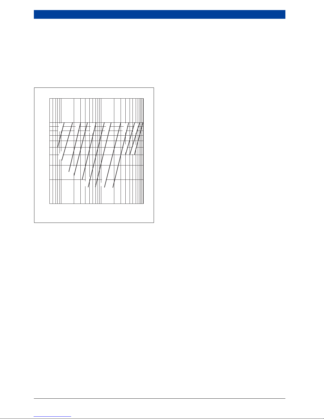
3.5 Characteristics
3.5.1 Pressure loss on the water side
The pressure loss on the water side is the pressure
differential between the boiler flow and return
connections. It depends on the boiler size (and the
internal diameter of the connectors) and the flow rate.
The graph in Fig. 14 shows the pressure loss on the
water side for the UNIMAT UT-L boilers.
Fig. 14 Pressure loss on the water side for UNIMAT UT-L
boilers (for internal diameters of flow and return
connections
page 22)
Δp
H
pressure loss on the heating water side
V
H
Flow rate
200
100
40
50
20
30
10
5 10 10050 1000
500
V
H
[m3/h]
Δp
H
[mbar]
6 720 642 347-14.1il
DN40
DN65
DN100
DN150
DN250
DN350
DN50
DN80
DN125
DN200
DN300
DN400
Technical description | 25
6 720 807 794 (2013/04)UNIMAT
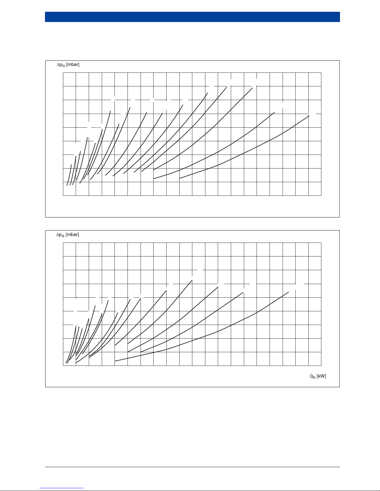
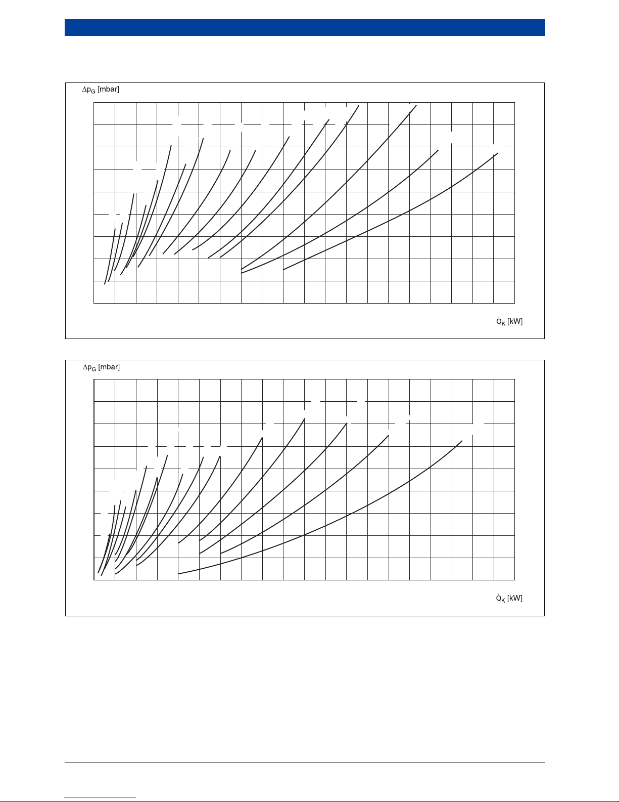
3.5.2 Pressure loss on the hot gas side
UNIMAT UT-L boiler
Fig. 15 Pressure loss on the hot gas side — overview 1
Fig. 16 Pressure loss on the hot gas side — overview 2
Δp
G
Pressure loss on the hot gas side
Q
K
Rated heating output
18
16
14
12
10
8
6
4
2
0
0 2000 4000 6000 8000 10000 12000 14000 16000 18000 20000
UT-L 4
UT-L 1
UT-L 10
UT-L 14
UT-L 18
UT-L 24
UT-L 28
UT-L 30
UT-L 34
UT-L 40
UT-L 42
UT-L 46
UT-L 50
UT-L 54
UT-L 58
UT-L 60
UT-L 64
QK [kW]
6 720 803 977-02.1ITL
18
16
14
12
10
8
6
4
2
0
0 2000 4000 6000 8000 10000 12000 14000 16000 18000 20000
UT-L 2/UT-L 6
UT-L 8
UT-L 12
UT-L 20
UT-L 16
UT-L 22
UT-L 26
UT-L 36
UT-L 38
UT-L 44
UT-L 48
UT-L 52
UT-L 56
UT-L 62
UT-L 32
6 720 803 977-03.1ITL
26 | Technical description
UNIMAT6 720 807 794 (2013/04)
UNIMAT UT-L boiler with condensing heat exchanger
Fig. 17 Pressure loss on the hot gas side — overview 1
Fig. 18 Pressure loss on the hot gas side — overview 2
Δp
G
Pressure loss on the hot gas side
QK Rated heating output
18
16
14
12
10
8
6
4
2
0
0 2000 4000 6000 8000 10000 12000 14000 16000 18000 20000
UT-L 4
UT-L 10
UT-L 14
UT-L 18
UT-L 24
UT-L 28
UT-L 30
UT-L 34
UT-L 40
UT-L 42
UT-L 46
UT-L 50
UT-L 54
UT-L 58
UT-L 60
UT-L 64
6 720 803 977-04.1ITL
18
16
14
12
10
8
6
4
2
0
0 2000 4000 6000 8000 10000 12000 14000 16000 18000 20000
UT-L 2
UT-L 6
UT-L 8
UT-L 16
UT-L 12
UT-L 20
UT-L 32
UT-L 36
UT-L 38
UT-L 44
UT-L 48
UT-L 52
UT-L 56
UT-L 62
UT-L 26
UT-L 22
6 720 803 977-05.1ITL
Technical description | 27
6 720 807 794 (2013/04)UNIMAT
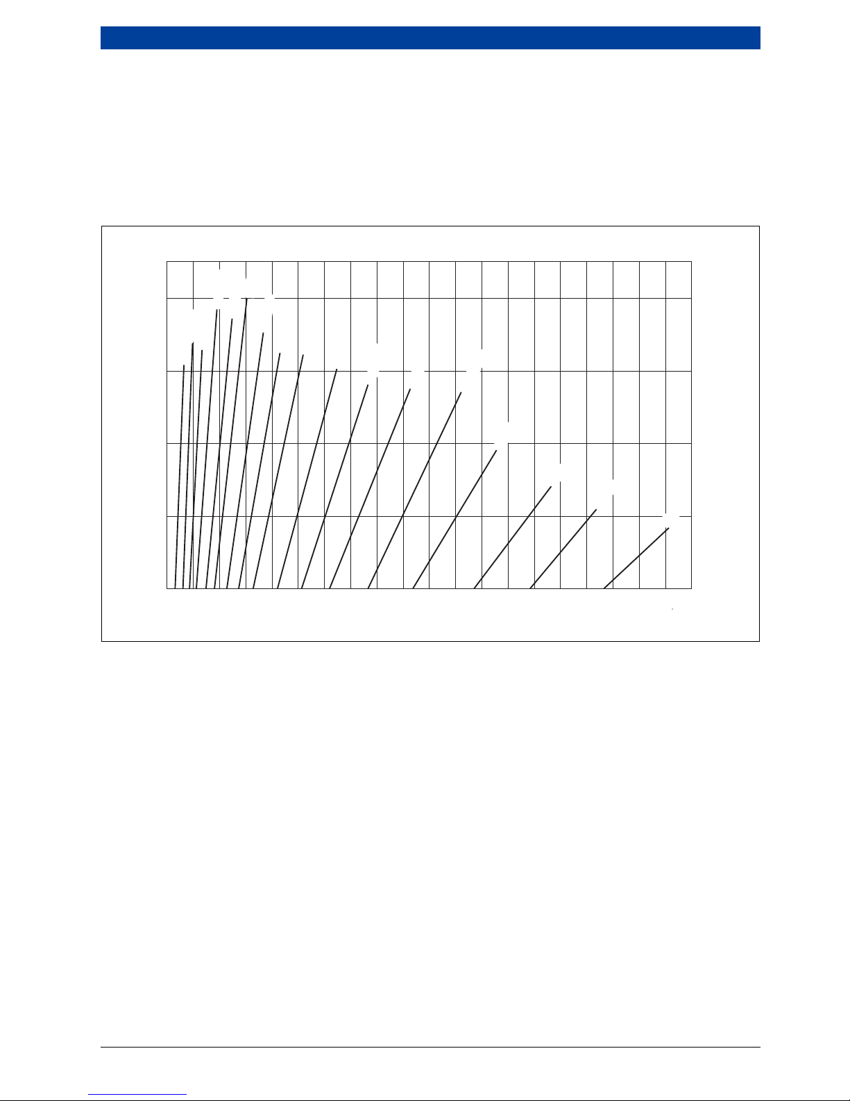
3.5.3 Combustion chamber volume load
To guarantee emissions values, some burner
manufacturers define aspects such as a maximum
combustion chamber volume load. Using the graphs in
Fig. 19 and Fig. 20, the most suitable boiler size for a
given combustion chamber volume load can be selected
for the UNIMAT UT-L boilers.
UNIMAT UT-L boiler
Fig. 19 Combustion chamber volume load for UNIMAT UT-L boiler, subject to the boiler output — overview 1
FVB Combustion chamber volume load
Q
B
Rated heating output
2,0
1, 9
1, 7
1, 5
1, 3
1,1
0
2000
4000
6000
8000
10000 14000
1600012000
18000
20000
UT-L 4
UT-L 10
UT-L 14
UT-L 18
UT-L 24
UT-L 28
UT-L 30
UT-L 34
UT-L 40
UT-L 42
UT-L 46
UT-L 50
UT-L 54
UT-L 58
UT-L 60
UT-L 64
QK [kW]
FVB [MW/m
3
]
6 720 803 977-06.1ITL
UT-L 1
 Loading...