

Page 1
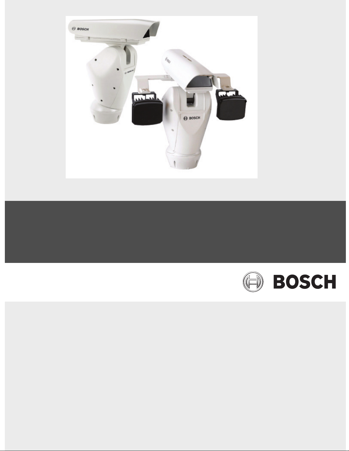
High-speed Positioning System
UPH Series
en Installation Manual
Page 2

High-speed Positioning System Table of Contents | en 3
Table of Contents
1Safety 5
1.1 Safety precautions 5
1.2 Important safety instructions 5
1.3 Important notices 8
1.4 FCC & ICES compliance 11
1.5 UL certification 12
1.6 Bosch notices 12
2 Unpacking 13
2.1 Description 13
2.2 Parts List 13
2.3 Tools Required 14
2.4 Safety Rules 14
3 Installing the Camera/Lens 15
3.1 Installing the Camera/Lens Mounting Tray 15
3.2 Connecting the Camera and Motorized Lens 17
4 Installing the High Speed Positioning System 18
4.1 Mounting the High Speed Positioning System 18
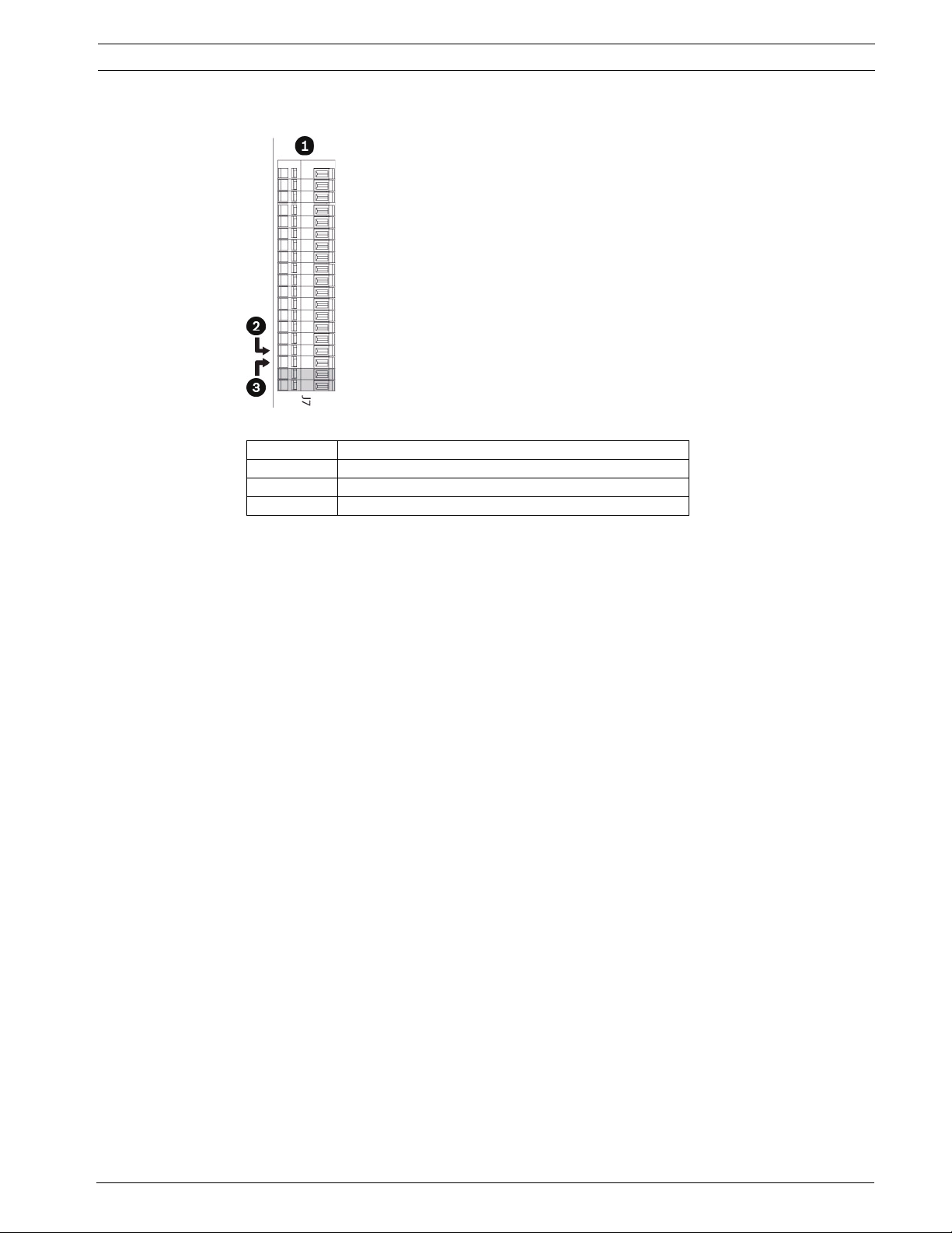
4.1.1 Wiring the Device 21
4.2 Wiring the Video Cable 22
4.3 Connecting the Power Supply 23
4.4 Wiring Biphase 24
4.5 RS-485/Pelco D 25
5 Connecting the Peripherals 26
5.1 Connecting to the Standard Base 26
5.2 Connecting to the IR360 Base 27
5.3 Fixing the Top Unit 27
5.4 IR360 Models (optional) 29
5.4.1 Fitting the Bracket 29
5.4.2 Assembling the Spotlights 30
5.4.3 Fitting the Spotlight on the Bracket 30
5.4.4 Infrared LED Spotlight Connections and Configurations 31
6 Configuring the Device 34
6.1 Factory Use Only 34
6.2 Protocol 34
6.3 Setting the Address 35
6.4 RS485 Line Termination 35
6.5 Biphase/Bilinx Termination 36
6.6 Connections 36
Bosch Security Systems, Inc. Installation Manual F.01U.164.491 | 2.0 | 2010.03
Page 3

4 en | Table of Contents High-speed Positioning System
7 On-screen Display (OSD) 39
8 Configuring the System 40
8.1 Language Menu 40
8.2 Display Setup Menu 40
8.2.1 Area Parameters Menu 41
8.2.2 Changing the Edit Text Menu 43
8.2.3 Display Parameters 44
8.3 Motion Parameters Menu 45
8.3.1 Speed Menu 45
8.3.2 Limits 46
8.3.3 Preset/Patrol/Autopan 47
8.3.4 Wiper-Washer 52
8.3.5 Alarms 53
8.4 Camera/Infrared Parameters 54
8.4.1 Lens Modules Parameters and Area Masking 54
8.4.2 Infrared Parameters 55
8.4.3 Illuminator/Dinion Configuration 55
8.5 Load Default Configuration 56
8.6 Setup Info Menu 57
9 Keyboard Commands List - Bosch 58
9.1 Keyboard Commands List - Pelco 58
9.2 Changing the Settings 59
9.3 Changing the Numeric Fields 59
10 Maintenance 60
10.1 Cleaning 60
10.2 Replacing the Fuses 60
11 Troubleshooting 61
11.1 Low and High Temperatures 62
11.2 Dimensions and Range of Movement 63
A Appendix A: Wiring Summary 65
B Appendix B: Connecting the Pump 67
B.1 Connecting a Washer System in the HAC-WAS05-20 67
F.01U.164.491 | 2.0 | 2010.03 Installation Manual Bosch Security Systems, Inc.
Page 4
High-speed Positioning System Safety | en 5
1Safety
1.1 Safety precautions
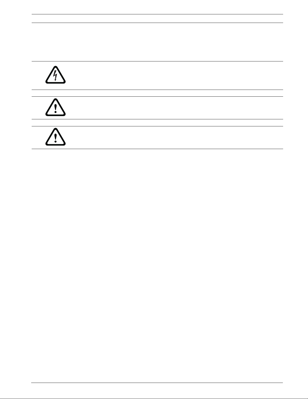
DANGER!
High risk: This symbol indicates an imminently hazardous situation such as “Dangerous
Voltage” inside the product.
If not avoided, this will result in an electrical shock, serious bodily injury, or death.
WARNING!
Medium risk: Indicates a potentially hazardous situation.
If not avoided, this could result in minor or moderate bodily injury.
CAUTION!
Low risk: Indicates a potentially hazardous situation.
If not avoided, this could result in property damage or risk of damage to the unit.
1.2 Important safety instructions
Read, follow, and retain for future reference all of the following safety instructions. Heed all
warnings on the unit and in the operating instructions before operating the unit.
1. Cleaning - Unplug the unit from the outlet before cleaning. Follow any instructions
provided with the unit. Generally, using a dry cloth for cleaning is sufficient but a moist,
fluff-free cloth or leather shammy may also be used. Do not use liquid cleaners or aerosol
cleaners.
2. Heat Sources - Do not install the unit near any heat sources such as radiators, heaters,
stoves, or other equipment (including amplifiers) that produce heat.
3. Ventilation - Any openings in the unit enclosure are provided for ventilation to prevent
overheating and ensure reliable operation. Do not block or cover these openings. Do not
place the unit in an enclosure unless proper ventilation is provided, or the manufacturer's
instructions have been adhered to.
4. Water - Do not use this unit near water, for example near a bathtub, washbowl, sink,
laundry basket, in a damp or wet basement, near a swimming pool, in an outdoor
installation, or in any area classified as a wet location. To reduce the risk of fire or
electrical shock, do not expose this unit to rain or moisture.
5. Object and liquid entry - Never push objects of any kind into this unit through openings
as they may touch dangerous voltage points or short-out parts that could result in a fire
or electrical shock. Never spill liquid of any kind on the unit. Do not place objects filled
with liquids, such as vases or cups, on the unit.
6. Lightning - For added protection during a lightning storm, or when leaving this unit
unattended and unused for long periods, unplug the unit from the wall outlet and
disconnect the cable system. This will prevent damage to the unit from lightning and
power line surges.
7. Controls adjustment - Adjust only those controls specified in the operating instructions.
Improper adjustment of other controls may cause damage to the unit. Use of controls or
adjustments, or performance of procedures other than those specified, may result in
hazardous radiation exposure.
8. Overloading - Do not overload outlets and extension cords. This can cause fire or
electrical shock.
Bosch Security Systems, Inc. Installation Manual F.01U.164.491 | 2.0 | 2010.03
Page 5
6 en | Safety High-speed Positioning System
9. Power supply cord and plug protection - Protect the power supply cord and plug from
foot traffic, being pinched by items placed upon or against them at electrical outlets, and
its exit from the unit. For units intended to operate with 230 VAC, 50 Hz, the power
supply cord must comply with the latest versions of IEC 60227. For units intended to
operate with 120 VAC, 60 Hz, the power supply cord must comply with the latest
versions of UL 62 and CSA 22.2 No.49.
10. Power disconnect - Units have power supplied to the unit whenever the power cord is
inserted into the power source. The power cord plug is the main power disconnect
device for switching off the voltage for all units.
11. Power sources - Operate the unit only from the type of power source indicated on the
label. Before proceeding, be sure to disconnect the power from the cable to be installed
into the unit.
– For battery powered units, refer to the operating instructions.
– For external power supplied units, use only the recommended or approved power
supplies.
– For limited power source units, this power source must comply with EN60950.
Substitutions may damage the unit or cause fire or shock.
– For 24 VAC units, voltage applied to the unit's power input should not exceed ±10%,
or 28 VAC. User-supplied wiring must comply with local electrical codes (Class 2
power levels). Do not ground the supply at the terminals or at the unit's power
supply terminals.
– If unsure of the type of power supply to use, contact your dealer or local power
company.
NOTICE!
Installation category (also called Overvoltage Category) specifies the level of mains voltage
surges that the equipment will be subjected to. The category depends upon the location of
the equipment, and on any external surge protection provided. Equipment in an industrial
environment, directly connected to major feeders/short branch circuits, is subjected to
Installation Category III. If this is the case, a reduction to Installation Category II is required.
This can be achieved by use of an isolating transformer with an earthed screen between
primary and secondary, or by fitting listed Surge Protective Devices (SPDs) from live to
neutral and from neutral to earth. Listed SPDs shall be designed for repeated limiting of
transient voltage surges, suitable rated for operating voltage and designated as follows:
– Type 2 (Permanently connected SPDs intended for installation on the load side of the
service equipment overcurrent device)
– Nominal Discharge Current (In) 20 kA min.
For example: FERRAZ SHAWMUT, STT2240SPG-CN, STT2BL240SPG-CN rated 120/240 VAC,
(In=20 kA)
12. Servicing - Do not attempt to service this unit yourself. Opening or removing covers may
expose you to dangerous voltage or other hazards. Refer all servicing to qualified service
personnel.
F.01U.164.491 | 2.0 | 2010.03 Installation Manual Bosch Security Systems, Inc.
Page 6

High-speed Positioning System Safety | en 7
13. Damage requiring service - Unplug the unit from the main AC power source and refer
servicing to qualified service personnel when any damage to the equipment has
occurred, such as:
– the power supply cord or plug is damaged;
– exposure to moisture, water, and/or inclement weather (rain, snow, etc.);
– liquid has been spilled in or on the equipment;
– an object has fallen into the unit;
– unit has been dropped or the unit cabinet is damaged;
– unit exhibits a distinct change in performance;
– unit does not operate normally when the user correctly follows the operating
instructions.
14. Replacement parts - Be sure the service technician uses replacement parts specified by
the manufacturer, or that have the same characteristics as the original parts.
Unauthorized substitutions may cause fire, electrical shock, or other hazards.
15. Safety check - Safety checks should be performed upon completion of service or repairs
to the unit to ensure proper operating condition.
16. Installation - Install in accordance with the manufacturer's instructions and in
accordance with applicable local codes.
NOTICE!
This product must only be used with a UR marked camera, rated 6-12 VDC with a maximum
power consumption of 5 W and a flammability class V-0 and Product Category NWGQ2,8.
17. Attachments, changes or modifications - Only use attachments/accessories specified by
the manufacturer. Any change or modification of the equipment, not expressly approved
by Bosch, could void the warranty or, in the case of an authorization agreement, authority
to operate the equipment.
Bosch Security Systems, Inc. Installation Manual F.01U.164.491 | 2.0 | 2010.03
Page 7
8 en | Safety High-speed Positioning System
1.3 Important notices
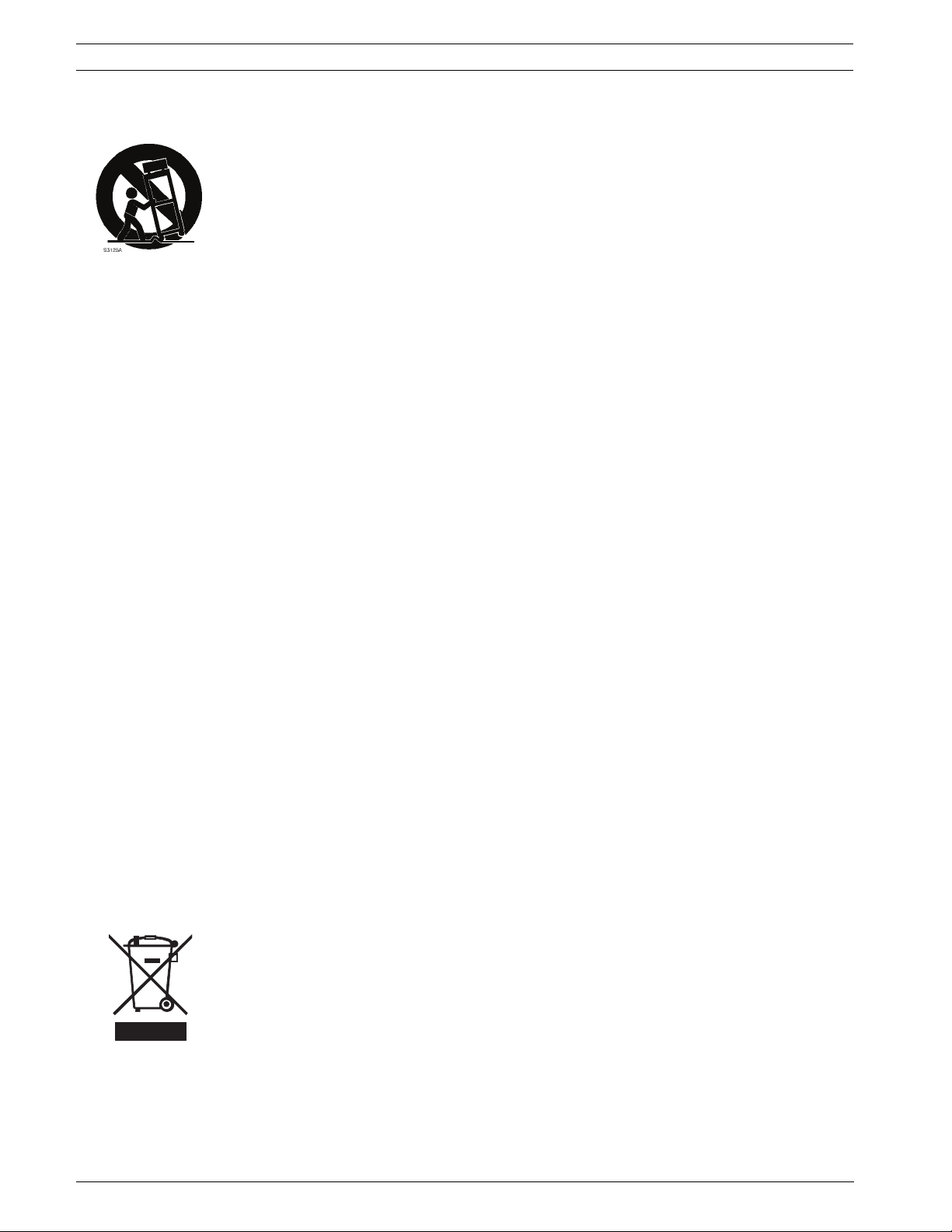
Accessories - Do not place this unit on an unstable stand, tripod, bracket, or mount. The unit
may fall, causing serious injury and/or serious damage to the unit. Use only with the cart,
stand, tripod, bracket, or table specified by the manufacturer. When a cart is used, use
caution and care when moving the cart/apparatus combination to avoid injury from tip-over.
Quick stops, excessive force, or uneven surfaces may cause the cart/unit combination to
overturn. Mount the unit per the manufacturer's instructions.
All-pole power switch - Incorporate an all-pole power switch, with a contact separation of at
least 3 mm in each pole, into the electrical installation of the building. If it is needed to open
the housing for servicing and/or other activities, use this all-pole switch as the main
disconnect device for switching off the voltage to the unit.
Battery replacement - A lithium battery is located inside the unit enclosure. To avoid danger
of explosion, replace the battery as per instructions. Replace only with the same or equivalent
type recommended by the manufacturer. Dispose of the replaced battery in an
environmentally friendly way and not with other solid waste. Refer all servicing to qualified
service personnel.
Camera grounding - For mounting the camera in potentially damp environments, ensure to
ground the system using the ground connection of the power supply connector (see section:
Connecting external power supply).
Camera lens - An assembled camera lens in the outdoor housing must comply and be tested
in accordance with UL/IEC60950. Any output or signal lines from the camera must be SELV or
Limited Power Source. For safety reasons the environmental specification of the camera lens
assembly must be within the environmental specification of -10 °C (14 °F) to 50 °C (122 °F).
Camera signal - Protect the cable with a primary protector if the camera signal is beyond 140
feet, in accordance with NEC800 (CEC Section 60).
Coax grounding:
– Ground the cable system if connecting an outside cable system to the unit.
– Connect outdoor equipment to the unit's inputs only after this unit has had its grounding
plug connected to a grounded outlet or its ground terminal is properly connected to a
ground source.
– Disconnect the unit's input connectors from outdoor equipment before disconnecting
the grounding plug or grounding terminal.
– Follow proper safety precautions such as grounding for any outdoor device connected to
this unit.
U.S.A. models only - Section 810 of the National Electrical Code, ANSI/NFPA No.70, provides
information regarding proper grounding of the mount and supporting structure, grounding of
the coax to a discharge unit, size of grounding conductors, location of discharge unit,
connection to grounding electrodes, and requirements for the grounding electrode.
Disposal - Your Bosch product was developed and manufactured with high-quality material
and components that can be recycled and reused. This symbol means that electronic and
electrical appliances, which have reached the end of their working life, must be collected and
disposed of separately from household waste material. Separate collecting systems are
usually in place for disused electronic and electrical products. Please dispose of these units
at an environmentally compatible recycling facility, per European Directive 2002/96/EC.
Electronic Surveillance - This device is intended for use in public areas only. U.S. federal law
strictly prohibits surreptitious recording of oral communications.
Environmental statement - Bosch has a strong commitment towards the environment. This
unit has been designed to respect the environment as much as possible.
F.01U.164.491 | 2.0 | 2010.03 Installation Manual Bosch Security Systems, Inc.
Page 8

High-speed Positioning System Safety | en 9
Electrostatic-sensitive device - Use proper CMOS/MOS-FET handling precautions to avoid
electrostatic discharge.
NOTE: Wear required grounded wrist straps and observe proper ESD safety precautions when
handling the electrostatic-sensitive printed circuit boards.
Fuse rating - For protection of the device, the branch circuit protection must be secured with
a maximum fuse rating as indicated in the manual. This must be in accordance with NEC800
(CEC Section 60).
Grounding and polarization - This unit may be equipped with a polarized alternating current
line plug (a plug with one blade wider than the other blade). This safety feature allows the
plug to fit into the power outlet in only one way. If unable to insert the plug fully into the
outlet, contact a locally certified electrician to replace the obsolete outlet. Do not defeat the
safety purpose of the polarized plug.
Alternately, this unit may be equipped with a 3-pole grounding plug (a plug with a third pin for
earth grounding). This safety feature allows the plug to fit into a grounded power outlet only.
If unable to insert the plug into the outlet, contact a locally certified electrician to replace the
obsolete outlet. Do not defeat the safety purpose of the grounding plug.
Moving - Disconnect the power before moving the unit. Move the unit with care. Excessive
force or shock may damage the unit and the hard disk drives.
Outdoor signals - The installation for outdoor signals, especially regarding clearance from
power and lightning conductors and transient protection, must be in accordance with NEC725
and NEC800 (CEC Rule 16-224 and CEC Section 60).
Permanently connected equipment - Incorporate a readily accessible disconnect device
external to the equipment.
Pluggable equipment - Install the socket outlet near the equipment so it is easily accessible.
Power resupply - If the unit is forced to power down due to exceeding the specified operating
temperatures, disconnect the power cord, wait for at least 30 seconds, and then reconnect
the power cord.
Power lines - Do not locate the camera near overhead power lines, power circuits, or
electrical lights, nor where it may contact such power lines, circuits, or lights.
SELV - All the input/output ports are Safety Extra Low Voltage (SELV) circuits. SELV circuits
should only be connected to other SELV circuits.
Because the ISDN circuits are treated like telephone-network voltage, avoid connecting the
SELV circuit to the Telephone Network Voltage (TNV) circuits.
Bosch Security Systems, Inc. Installation Manual F.01U.164.491 | 2.0 | 2010.03
Page 9
10 en | Safety High-speed Positioning System
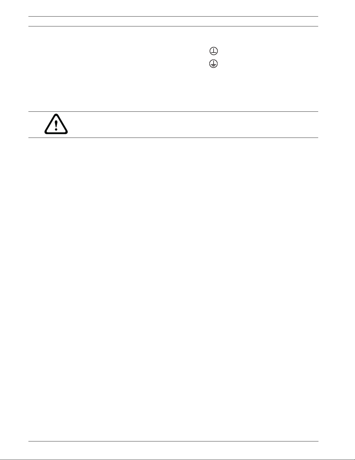
System ground/Safety ground
System (video) ground is indicated by the symbol .
Safety (power) ground is indicated by the symbol .
The system ground is only used to comply with safety standards or installation practices in
certain countries. Bosch does not recommend connecting system ground to safety ground
unless it is explicitly required. However, if the system ground and safety ground are
connected and grounding loops are causing interference in the video signal, use an isolation
transformer (available separately from Bosch).
CAUTION!
Connecting System ground to Safety ground may result in ground loops that can disrupt the
CCTV system.
Video loss - Video loss is inherent to digital video recording; therefore, Bosch Security
Systems cannot be held liable for any damage that results from missing video information. To
minimize the risk of lost digital information, Bosch Security Systems recommends multiple,
redundant recording systems, and a procedure to back up all analog and digital information.
F.01U.164.491 | 2.0 | 2010.03 Installation Manual Bosch Security Systems, Inc.
Page 10

High-speed Positioning System Safety | en 11
1.4 FCC & ICES compliance
FCC Information
(U.S.A. and Canadian Models Only)
This device complies with part 15 of the FCC Rules. Operation is subject to the following
conditions:
– this device may not cause harmful interference, and
– this device must accept any interference received, including interference that may cause
undesired operation.
NOTE: This equipment has been tested and found to comply with the limits for a Class A
digital device, pursuant to Part 15 of the FCC Rules and ICES-003 of Industry Canada. These
limits are designed to provide reasonable protection against harmful interference when the
equipment is operated in a commercial environment. This equipment generates, uses, and
radiates radio frequency energy and, if not installed and used in accordance with the
instruction manual, may cause harmful interference to radio communications. Operation of
this equipment in a residential area is likely to cause harmful interference, in which case the
user will be required to correct the interference at his expense.
Intentional or unintentional modifications, not expressly approved by the party responsible
for compliance, shall not be made. Any such modifications could void the user's authority to
operate the equipment. If necessary, the user should consult the dealer or an experienced
radio/television technician for corrective action.
The user may find the following booklet, prepared by the Federal Communications
Commission, helpful: How to Identify and Resolve Radio-TV Interference Problems. This booklet
is available from the U.S. Government Printing Office, Washington, DC 20402, Stock No. 004000-00345-4.
Informations FCC et ICES
(modèles utilisés aux États-Unis et au Canada uniquement)
Ce produit est conforme aux normes FCC partie 15. la mise en service est soumises aux deux
conditions suivantes :
– cet appareil ne peut pas provoquer d'interférence nuisible et
– cet appareil doit pouvoir tolérer toutes les interférences auxquelles il est soumit, y
compris les interférences qui pourraient influer sur son bon fonctionnement.
AVERTISSEMENT: Suite à différents tests, cet appareil s’est révélé conforme aux exigences
imposées aux appareils numériques de Classe A en vertu de la section 15 du règlement de la
Commission fédérale des communications des États-Unis (FCC). Ces contraintes sont destinées
à fournir une protection raisonnable contre les interférences nuisibles quand l'appareil est
utilisé dans une installation commerciale. Cette appareil génère, utilise et émet de l'energie
de fréquence radio, et peut, en cas d'installation ou d'utilisation non conforme aux
instructions, générer des interférences nuisibles aux communications radio. L’utilisation de ce
produit dans une zone résidentielle peut provoquer des interférences nuisibles. Le cas
échéant, l’utilisateur devra remédier à ces interférences à ses propres frais.
Au besoin, l’utilisateur consultera son revendeur ou un technicien qualifié en radio/télévision,
qui procédera à une opération corrective. La brochure suivante, publiée par la Commission
fédérale des communications (FCC), peut s’avérer utile : How to Identify and Resolve Radio-TV
Interference Problems (Comment identifier et résoudre les problèmes d’interférences de radio
et de télévision). Cette brochure est disponible auprès du U.S. Government Printing Office,
Washington, DC 20402, États-Unis, sous la référence n° 004-000-00345-4.
Bosch Security Systems, Inc. Installation Manual F.01U.164.491 | 2.0 | 2010.03
Page 11

12 en | Safety High-speed Positioning System
NOTICE!
This is a class A product. In a domestic environment this product may cause radio
interference, in which case the user may be required to take adequate measures.
1.5 UL certification
Disclaimer
Underwriter Laboratories Inc. ("UL") has not tested the performance or reliability of the
security or signaling aspects of this product. UL has only tested fire, shock and/or casualty
hazards as outlined in UL's Standard(s) for Safety for Closed Circuit Television Equipment, UL
2044. UL Certification does not cover the performance or reliability of the security or signaling
aspects of this product.
UL MAKES NO REPRESENTATIONS, WARRANTIES, OR CERTIFICATIONS WHATSOEVER
REGARDING THE PERFORMANCE OR RELIABILITY OF ANY SECURITY OR SIGNALING RELATED
FUNCTIONS OF THIS PRODUCT.
Disclaimer
Underwriter Laboratories Inc. ("UL") has not tested the performance or reliability of the
security or signaling aspects of this product. UL has only tested fire, shock and/or casualty
hazards as outlined in UL's Standard(s) for Safety for Information Technology Equipment, UL
60950-1. UL Certification does not cover the performance or reliability of the security or
signaling aspects of this product.
UL MAKES NO REPRESENTATIONS, WARRANTIES, OR CERTIFICATIONS WHATSOEVER
REGARDING THE PERFORMANCE OR RELIABILITY OF ANY SECURITY OR SIGNALINGRELATED FUNCTIONS OF THIS PRODUCT.
1.6 Bosch notices
Copyright
This manual is the intellectual property of Bosch Security Systems and is protected by
copyright. All rights reserved.
Trademarks
All hardware and software product names used in this document are likely to be registered
trademarks and must be treated accordingly.
NOTE:
This manual has been compiled with great care and the information it contains has been
thoroughly verified. The text was complete and correct at the time of printing. The ongoing
development of the products may mean that the content of the user guide can change without
notice. Bosch Security Systems accepts no liability for damage resulting directly or indirectly
from faults, incompleteness or discrepancies between the user guide and the product
described.
More information
For more information please contact the nearest Bosch Security Systems location or
visitwww.boschsecurity.com
F.01U.164.491 | 2.0 | 2010.03 Installation Manual Bosch Security Systems, Inc.
Page 12

High-speed Positioning System Unpacking | en 13
2 Unpacking
This equipment should be unpacked and handled with care. If an item appears to have been
damaged in shipment, notify the shipper immediately.
Verify that all the parts listed in Section 2.2 Parts List, page 13 are included. If any items are
missing, notify your Bosch Security Systems Sales or Customer Service Representative.
The original packing carton is the safest container in which to transport the unit and must be
used if returning the unit for service. Save it for possible future use.
2.1 Description
The Bosch High-Speed Positioning System is a complete, high-performance, high quality
solution that can pan 360 degrees continuously at speeds of up to 100 degrees per second.
An extensive range of options lets you tailor the system to your specific requirements. For
example, a wide variety of video cameras and lenses, including the optimized Dinion 2X
camera and zoom lens combinations, are available.
2.2 Parts List
The High Speed Positioning System includes the following components:
– One (1) Unitized Pan Head (UPH) device
– One (1) Camera/Lens Mounting Tray
– The following Accessory Bags
– Cable and Screws:
One (1) coaxial cable
Four (4) M4 x 10 mm screws; for tray mounting
Four (4) 4 mm washers; for tray mounting
Two (2) tie wraps, 102 x 2.5 mm
One (1) tie wrap, 180 x 3.5 mm
– Power Connection:
One (1) 3 mm Allen wrench
Two (2) tie wraps, 102 x 2.5 mm
One (1) plastic tube (power wiring cover)
Two (2) conduit plugs for cable glands
One (1) safety label
– Desiccant:
One (1) desiccant bag
One (1) mounting plate
Two (2) M4 x 10 mm screws self-tapping, galvanized (Zn)
One (1) 4 mm Allen wrench
– One (1) instruction manual
– One (1) box containing:
– One (1) PTZ base with power supply and one (1) desiccant bag
– Four (4) inox M5 x 20 mm screws, hexagonal head;
– Four (4) washers/gaskets (2015 O-ring)
– IR bracket with four (4) inox M5 x 14 mm screws, hexagonal head; four (4) M5 lock
washers UNI 1751; IR model only
Bosch Security Systems, Inc. Installation Manual F.01U.164.491 | 2.0 | 2010.03
Page 13
14 en | Unpacking High-speed Positioning System
2.3 Tools Required
– Small, straight-blade screwdriver - 2.5 mm (0.1 in.)
2.4 Safety Rules
To ensure safety, the following warnings are specified:
– The device must be installed and maintained by skilled technical personnel.
– Connect the device to a power source corresponding to the indications given on the
marking label.
– The device has been designed for permanent installation in a building or other suitable
structure.
– Moving parts may result in risk of injury, therefore, the device should be mounted so that
it is accessible only to the technician/installer.
– Place the safety warning label near the UPH.
– Before carrying out any technical work on the UPH, tilt the UPH all the way up or all the
way down, then disconnect the power supply and cables from all other devices.
– Do not use power cables with signs of wear or aging.
– Do not use the device in the presence of inflammable substances.
– Do not allow children or unauthorized personnel to use the device.
– The device should be switched OFF when the power supply has been disconnected and
the connecting cables to other devices have been removed.
– Keep this manual for future reference.
CAUTION!
Before disconnecting the power supply to the UPH, tilt the device either all the way up or all
the way down. When the UPH loses power, depending on how it is positioned, the unit may
drop slightly forward or backward. Therefore, failure in correctly positioning the UPH before
disconnecting the power supply may result in personal injury or possible damage to the
device.
F.01U.164.491 | 2.0 | 2010.03 Installation Manual Bosch Security Systems, Inc.
Page 14
High-speed Positioning System Installing the Camera/Lens | en 15
3 Installing the Camera/Lens
This chapter outlines the procedures needed to install the camera/lens inside the UPH
housing. Installation should be done only by qualified service personnel in conformance to all
local codes.
Note: For models that already have the camera/lens installed, go to Section 4 Installing the
High Speed Positioning System.
NOTICE!
This product must only be used with a UR marked camera, rated 6-12 VDC with a maximum
power consumption of 5 W and a flammability class V-0 and Product Category NWGQ2,8.
3.1 Installing the Camera/Lens Mounting Tray
For some models of the High Speed Positioning System, the customer is responsible for
installing the camera and lenses.
To install the camera, proceed as follows:
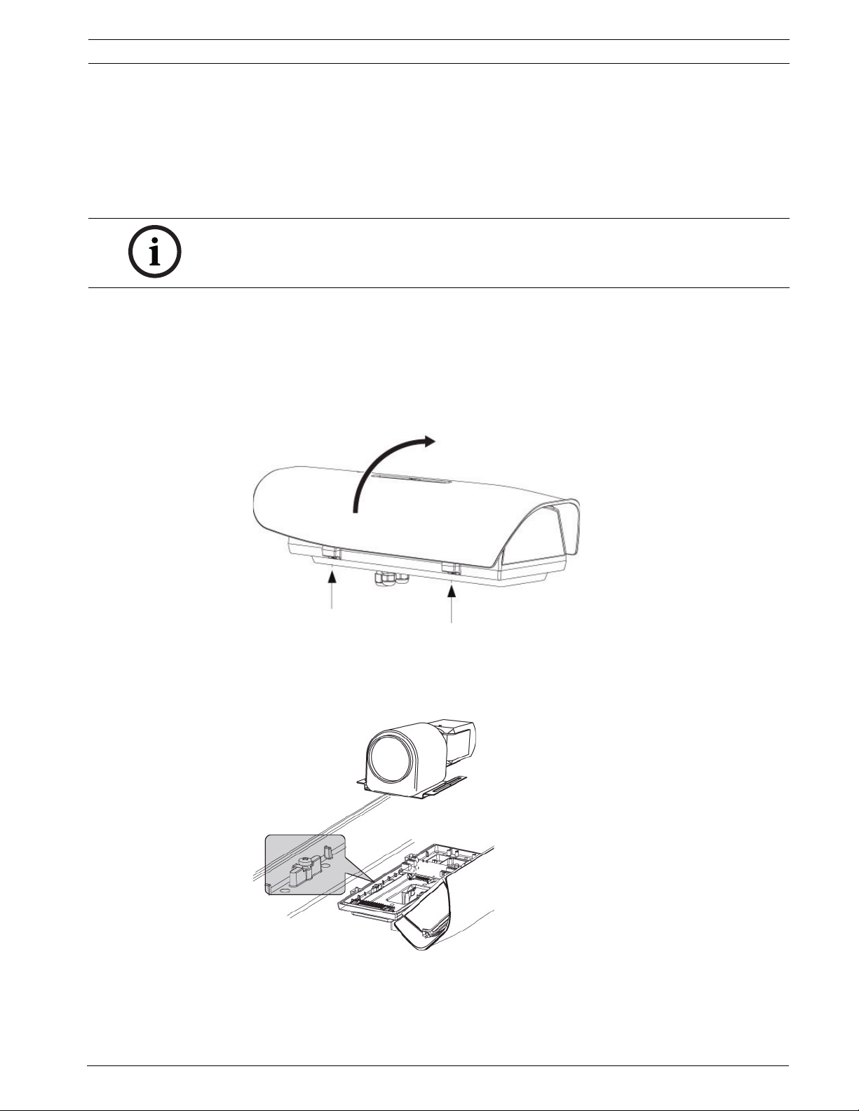
1. Open the housing by loosening the captive screws on the side and swivel the upper body
until it is completely open (do not remove screws completely).
Figure 3.1 Loosen Screws and Open Lid of Housing
2. Remove the camera/lens mounting tray from the packing box.
3. Install the camera/lens mounting tray attached in the correct position inside the housing
at the location shown below.
Figure 3.2 Install Camera/Tray
Bosch Security Systems, Inc. Installation Manual F.01U.164.491 | 2.0 | 2010.03
Page 15
16 en | Installing the Camera/Lens High-speed Positioning System
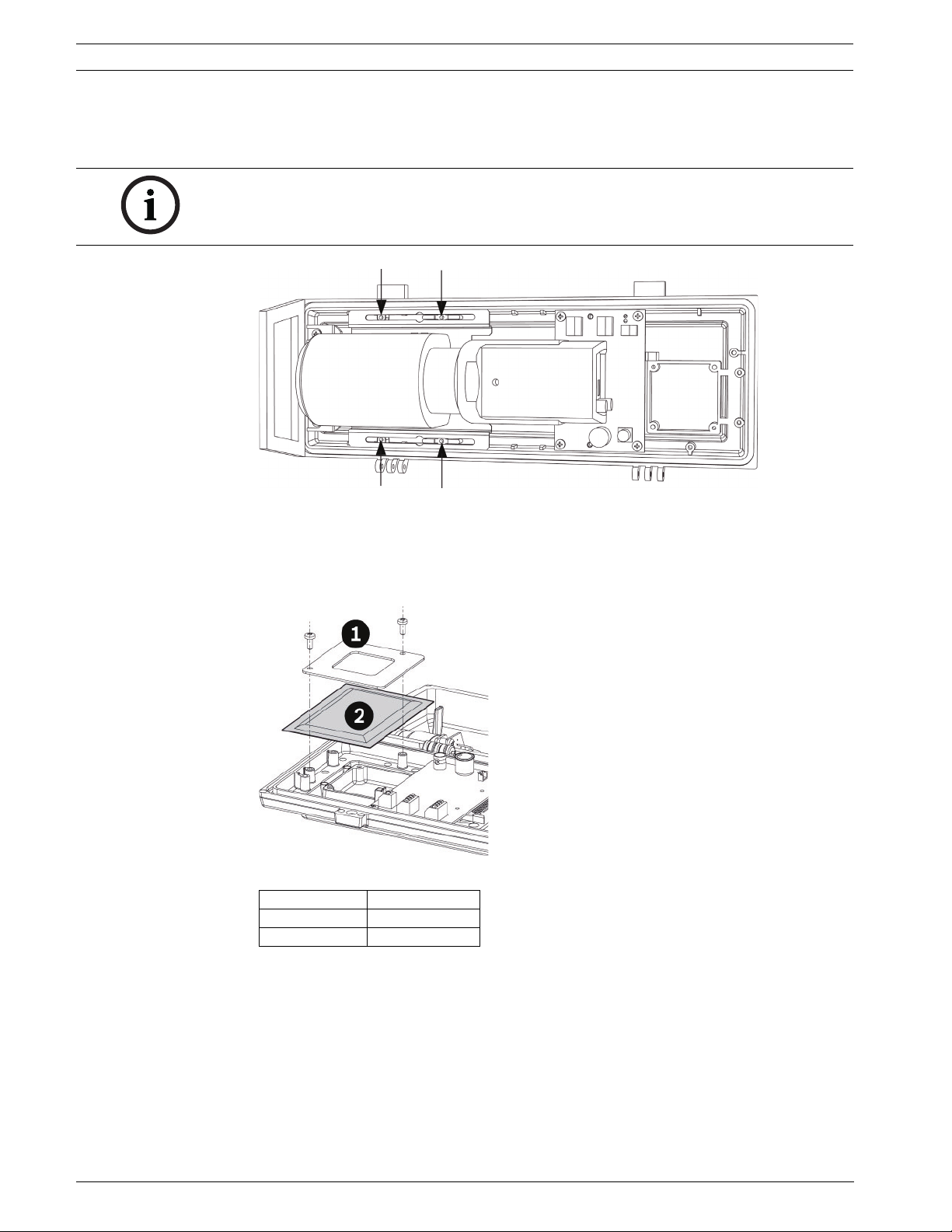
4. Reposition the camera/lens mounting tray sliding it forward so the lens is as close to the
front window as possible. Insert and tighten the four M4 x 10 screws and the four
washers (contained in the Cable and Screws accessory bag) as shown in Figure 3.3.
NOTICE!
A partially blocked view may result if the camera is not pushed up close to the front of the
housing.
Figure 3.3 Attach Camera to Housing
5. Locate the sealed plastic bag containing the desiccant bag.
6. Place the desiccant bag inside the housing as shown in Figure 3.4, with the desiccant bag
secured into position by the metal fixing accessory and two fixing screws (supplied in the
Desiccant accessory bag).
Figure 3.4 Attach Desiccant Bag
Reference # Description
1Bracket
2 Desiccant Bag
7. Remove the camera packaging material.
8. Make sure the gasket is present and in good condition.
F.01U.164.491 | 2.0 | 2010.03 Installation Manual Bosch Security Systems, Inc.
Page 16
High-speed Positioning System Installing the Camera/Lens | en 17
J22
J27
J26
J5
J2
J7
J1
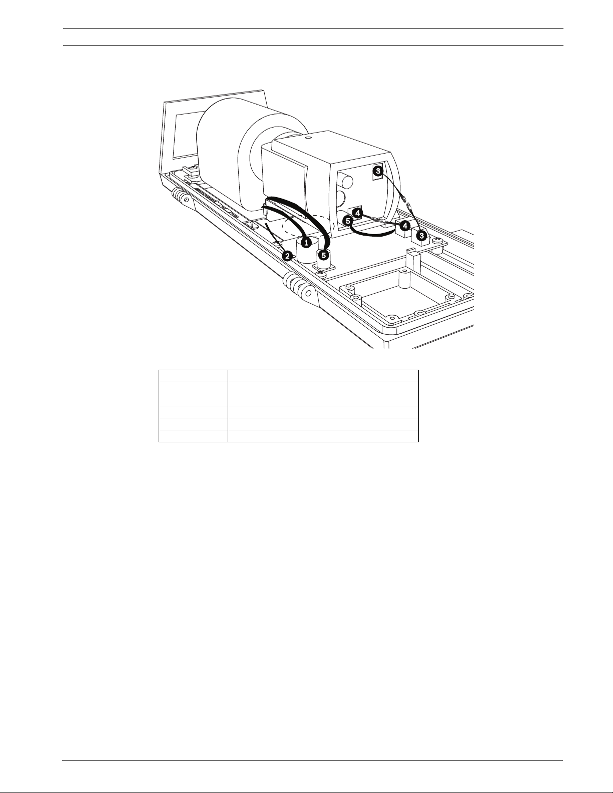
3.2 Connecting the Camera and Motorized Lens
Figure 3.5 Make Connections (LTC 0498 Dinion 2X camera shown)
Reference Description
1 8-pin DIN connector
2 4-pin iris override connector
3 2-pin power cable
4 4-pin alarm cable
5 VIDEO IN connector
1. Connect the 8-pin DIN connector zoom and focus control cable from the camera to the J5
location on the board. Secure cable in up-right position by using supplied tie wrap.
2. If applicable (LTC 3293/30 manual override units only), connect the 4-pin iris override
connector from the camera to the J2 location on the board.
3. Connect the 2-pin power cable from the camera to the mating connector from the J26
location on the board.
4. Connect the 4-pin alarm cable from the camera to the mating connector from the J27
location on the board.
5. Connect the “L” adapter end of the coax cable (supplied in the Cable and Screw
accessory bag) to the coax connector on the back of the camera. VIDEO IN connector
from the camera to the J1 location on the board.
6. Route the other end of the coax cable along the right side (looking from behind) of the
camera and under the camera tray. Then, connect the coax cable to the J1 location on
the board.
7. Wrap one of the 102 x 2.5 mm tie wraps around the zoom and focus cable and the coax
cable, near the location where the cables connect to the board.
8. Close and secure the housing lid.
Bosch Security Systems, Inc. Installation Manual F.01U.164.491 | 2.0 | 2010.03
Page 17
18 en | Installing the High Speed Positioning System High-speed Positioning System
1
2
4 Installing the High Speed Positioning System
This chapter outlines the procedures needed to mount the High Speed Positioning System.
Installation should be done only by qualified service personnel in conformance to all local
codes.
NOTICE!
The High-speed Positioning System unit cannot be mounted upside down! This configuration
stresses bearings and mechanical components; no liabilities are accepted and all warranties
are void.
NOTICE!
In accordance with NEC laws, you may be required to install an external power junction box.
4.1 Mounting the High Speed Positioning System
The High Speed Positioning System can be mounted with either a wall mount (MTC-WUPH,
sold separately) or a pole mount (MTC-PUPH, sold separately).
To install the device, proceed as follows:
1. Determine the location to install the device.
– When selecting a location, a minimum clearance of 300 mm (12 in.) in front of the
unit and 300 mm (12 in.) in back of the unit is required to facilitate component
removal and installation.
– The device should be installed vertically. Any other position could impair the
performance of the device.
– Do not attach the device upside down.
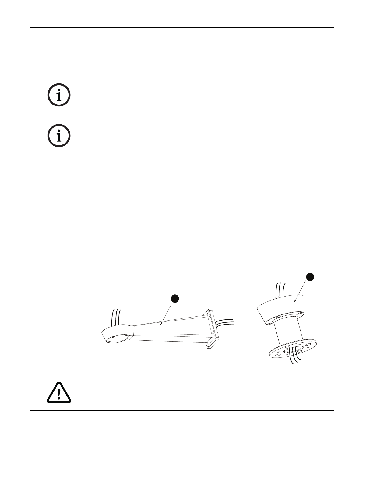
2. Insert the cables into the optional wall or pole mount so they protrude approximately
0.5 m (19.7 in.).
.5 m
19.7 in.
2
.5 m
19.7 in.
MTC-WUPH
Figure 4.1 Optional Wall Mount (1) or Pole Mount (2)
1
MTC-PUPH
WARNING!
The cables should not be accessible by unauthorized personnel; cables should be secured to
fixed locations at appropriate intervals to bare the weight of the cables, for example, cables
running inside a tall camera pole.
F.01U.164.491 | 2.0 | 2010.03 Installation Manual Bosch Security Systems, Inc.
Page 18
High-speed Positioning System Installing the High Speed Positioning System | en 19
7
WARNING!
Be sure to use appropriately strong and load bearing bolts and other fixing materials when
installing any UPH mountings to any surface.
When the MTC-WUPH Wall Mount is fixed to a wall, each fixing dowel must be able to support
a traction load of 300 dN or more. It is necessary to use 8 mm (0.315 in.) diameter bolts with
appropriate length. Ensure the clamping system is able to support at least four times the
weight of the entire equipment, including swinging, lenses, and camera.
3. Attach the optional wall or pole mount according to the specific mounting manual.
Part Description
MTC-PUPH Outdoor Pole Mount for UPH Series
MTC-WUPH Outdoor Wall Mount for UPH Series
MTC-POLE-W Pole Adapter for MTC-WUPH
MTC-CORN-W Corner Adapter for MTC-WUPH
Note: If using a washer kit, the spray support should be installed before positioning and
wiring the pan/tilt.
WARNING!
Take special care when attaching and fastening down the apparatus. If the mount is to be
attached to a concrete surface you must use dowel pins with a traction torque rating of at
least 300 dN each.
For a metal surface, use screws with a diameter of at least 8 mm of an appropriate length. The
clamping system must be support at least four times the weight of the entire equipment,
including swinging, lenses, and camera.
4. Remove desiccant bag from inside the base and dispose.
5. Remove the cable glands from the base and fit the gasket / seal ring.
6. Insert the cables into the cable glands while holding the base approximately 20 cm from
the bracket. Note that there are three glands; one for power, one for video, and one for
data / IO cables.
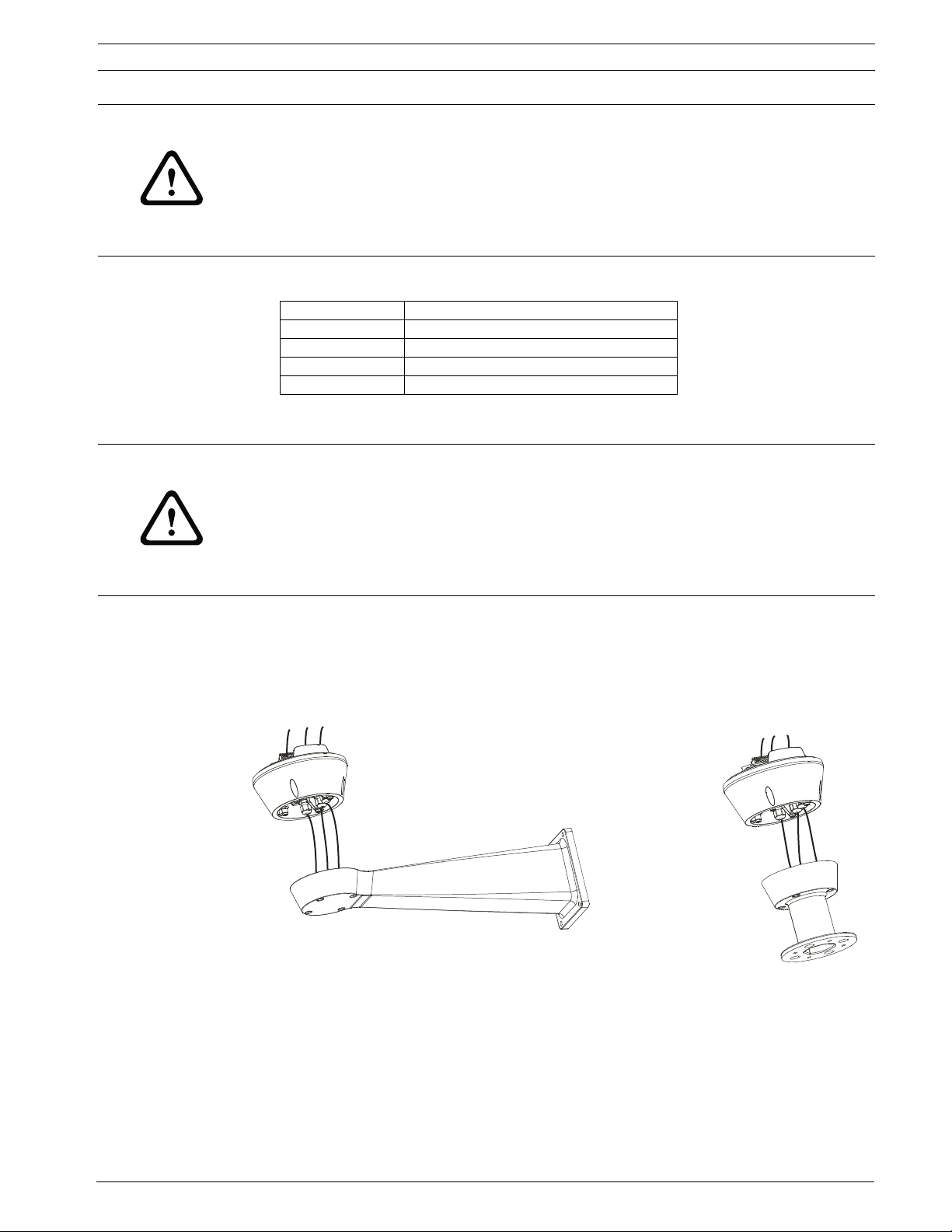
Figure 4.2 Inserting the Cables through the Cable Glands
7. Securely lock the cable glands into place (gland closing torque 5 Nm); they accept cables
5-10 mm (0.2-0.39 in.) in diameter. The gland closing torque is 5 Nm; use a calibrated
torque wrench to ensure closure.
Note: The cable glands can be changed to accept smaller 3-7 mm diameter cables by
using the two (2) conduit plugs provided.
8. Position the base on the optional wall or pole mount, guiding the cables so that they are
positioned inside the wall or pole mount (see Figure 4.3).
Bosch Security Systems, Inc. Installation Manual F.01U.164.491 | 2.0 | 2010.03
Page 19
20 en | Installing the High Speed Positioning System High-speed Positioning System
7
1
2
3
4
5
6
1
2
3
4
5
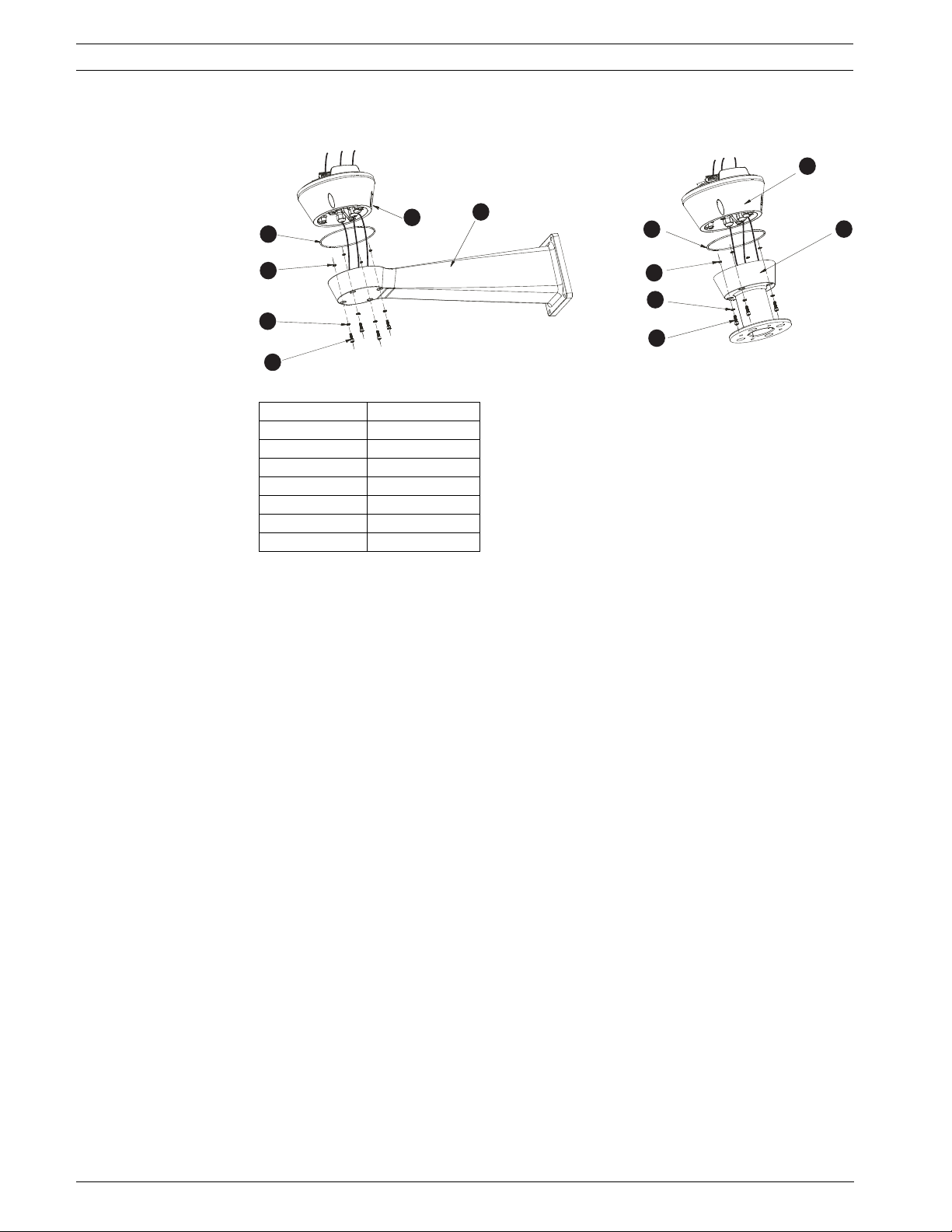
9. Fasten the base to the wall or pole mount with the supplied screws and washers (use a
calibrated torque wrench setting of 2.1 Nm).
Figure 4.3 Schematic Diagram
Reference Description
1 Base
2Gasket
3 Screw Ring
4Washer
5Screw
6Bracket
7Support
F.01U.164.491 | 2.0 | 2010.03 Installation Manual Bosch Security Systems, Inc.
Page 20
High-speed Positioning System Installing the High Speed Positioning System | en 21
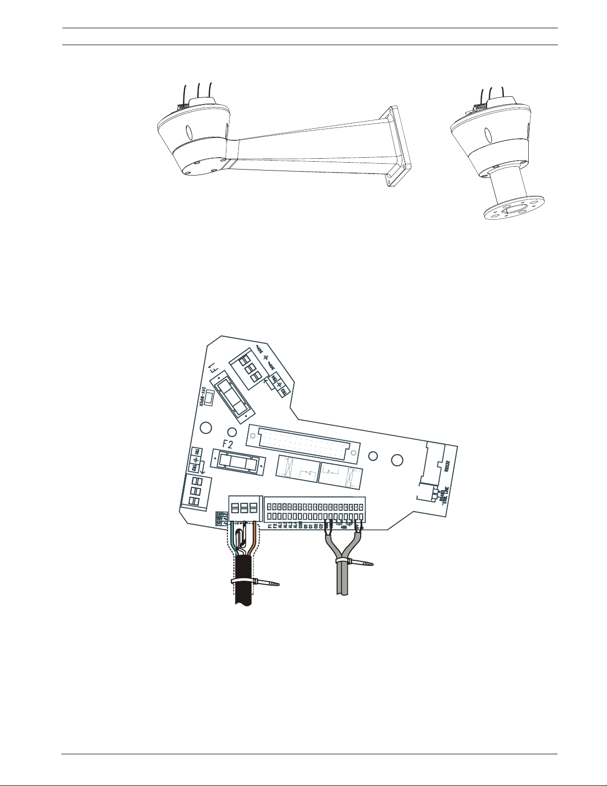
4.1.1 Wiring the Device
Figure 4.4 Preparing the Cables for Wiring
1. Cut the cables to approximately 152.4 mm (6 in.) (see Figure 4.4). The earth cable must
be longer then the power wires by approximately 10 mm or more to prevent
disconnection.
2. Cover the power cable with the plastic tube provided and fix it with the tie thread.
3. Make a group with all signal cables and fix them with the tie thread. See the illustration
below for a proper cable connection; note: IR360 version board will vary slightly due to
the signals connector having 16 lines as compared to 19 as shown below.
Figure 4.5 Tie Threads used to Group and Secure Cables
Bosch Security Systems, Inc. Installation Manual F.01U.164.491 | 2.0 | 2010.03
Page 21
22 en | Installing the High Speed Positioning System High-speed Positioning System
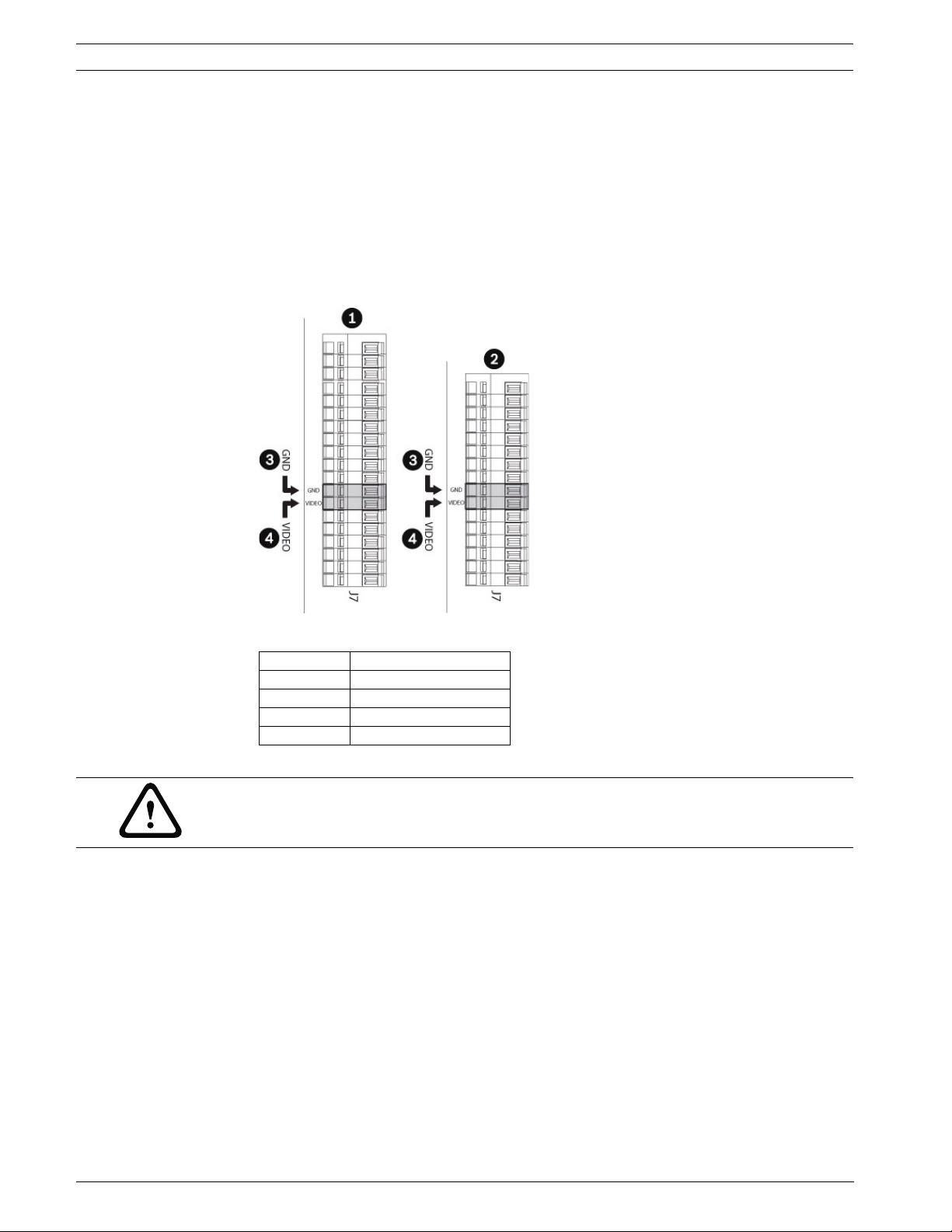
4.2 Wiring the Video Cable
To wire the video cable, proceed as follows:
1. Strip the video cable with a pair of wire strippers.
2. Cut the length of the center conductor and the braid to approximately 30 mm (1.2 in.).
3. Twist the braid into a single conductor.
4. Use a small screwdriver to press down on the GND push latch (see Figure 4.6) and attach
the single braid to the GND terminal.
5. Use a small screwdriver to press down on the VIDEO push latch (see Figure 4.6) and
attach the center conductor to the VIDEO terminal.
Figure 4.6 Wiring the Terminals
Reference Description
1 Standard - 19 pin
2 IR - 16 pin
3GND
4Video
Note: The above terminals support AWG 20 (0.5 mm2) to AWG 28 (0.08 mm2) cables.
WARNING!
The installation is type CDS (Cable Distribution System), do not connect it to SELV circuits.
To reduce risk of fire use only 26 AWG or larger line cord.
F.01U.164.491 | 2.0 | 2010.03 Installation Manual Bosch Security Systems, Inc.
Page 22
High-speed Positioning System Installing the High Speed Positioning System | en 23
4.3 Connecting the Power Supply
NOTICE!
Installation category (also called Overvoltage Category) specifies the level of mains voltage
surges that the equipment will be subjected to. The category depends upon the location of
the equipment, and on any external surge protection provided. Equipment in an industrial
environment, directly connected to major feeders/short branch circuits, is subjected to
Installation Category III. If this is the case, a reduction to Installation Category II is required.
This can be achieved by use of an isolating transformer with an earthed screen between
primary and secondary, or by fitting listed Surge Protective Devices (SPDs) from live to
neutral and from neutral to earth. Listed SPDs shall be designed for repeated limiting of
transient voltage surges, suitable rated for operating voltage and designated as follows:
– Type 2 (Permanently connected SPDs intended for installation on the load side of the
service equipment overcurrent device)
– Nominal Discharge Current (In) 20 kA min.
For example: FERRAZ SHAWMUT, STT2240SPG-CN, STT2BL240SPG-CN rated 120/240 VAC,
(In=20 kA)
The base with power supply box is available in three (3) power supply voltages (24 VAC,
120 VAC, or 230 VAC). Before proceeding with the installation, check the identification label
of the product to verify that the device coincides with the power supply requirements.
CAUTION!
When connecting the base, make sure the external power source is disconnected (the
disconnecting switch is open).
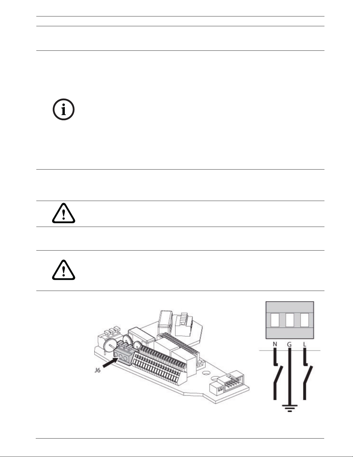
When the base is opened, the power supply board appears as shown below. To connect the
power supply, make the connections as seen in Figure 4.7.
WARNING!
For 24 VAC units intended for UL markets, use only a Class 2 UL listed power supply for all
models except the UPH-H-WDIR-24 (compliant with the local electrical codes). For UPH-HWDIR-24, the power must be provided by a UL listed power supply with a double insulation
transformer.
Figure 4.7 Power Supply Connections
Bosch Security Systems, Inc. Installation Manual F.01U.164.491 | 2.0 | 2010.03
Page 23
24 en | Installing the High Speed Positioning System High-speed Positioning System
To wire the power cable (not supplied), use the tables below to attach the appropriate
colored wire to the appropriate terminal.
Wire Color
24 VAC
1
Terminal Connection
Per local Installer Neutral
Per local Installer Live/Active
Green/Yellow Earth
1. For 24 VAC units intended for UL markets, use only a Class 2 UL
listed power supply for all models except the UPH-H-WDIR-24
(compliant with the local electrical codes). For UPH-H-WDIR-24, the
power must be provided by a UL listed power supply with a double
insulation transformer.
Wire Color
120 / 230 VAC
2
Terminal Connection
Blue Neutral
Brown Live/Active
Green/Yellow Earth
2. Use the appropriate junction box to connect the power supply line. Use a Class 2, UL listed power supply
WARNING!
For the standard models with 120/230 VAC power, an external junction box with a readily
accessible 2-pole disconnect device must be incorporated. For the IR model UPH-H-WDIR-24,
the 24 VAC power must be provided by a UL listed power supply with a double insulation
transformer.
Note: The power cable must be double insulated, each separate cable is individually
insulated, then contained in an outer insulated cover. The cable type must be chosen in
accordance with local and national wiring rules.
WARNING!
The device must be wired by skilled technical personnel. Never make any changes or
connections that are not described in this handbook. Failure to follow the instructions
indicated in this manual may result in system or safety hazards, thus invalidating the
guarantee.
WARNING!
When wiring for external/outdoor environments, be sure to use appropriately rated cables.
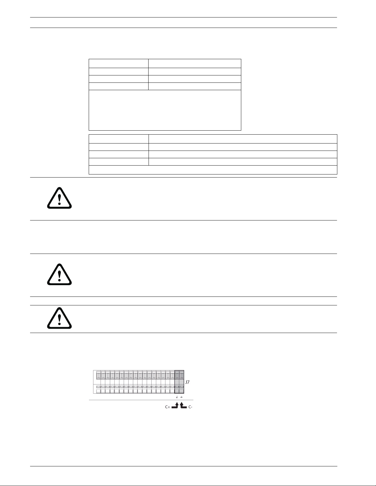
4.4 Wiring Biphase
To wire for Biphase, connect the C+ terminal wire to the B+ terminal and the C- terminal wire
to the B- terminal respectively.
Figure 4.8 Wiring for Biphase
F.01U.164.491 | 2.0 | 2010.03 Installation Manual Bosch Security Systems, Inc.
Page 24
High-speed Positioning System Installing the High Speed Positioning System | en 25
4.5 RS-485/Pelco D
Figure 4.9 Connecting for RS-485
Reference Description
1 Pelco D connections
2 RS485-2, A, connect to Pelco controller out TX (-)
3 RS485-2 B, connect to Pelco controller out TX (+)
Bosch Security Systems, Inc. Installation Manual F.01U.164.491 | 2.0 | 2010.03
Page 25
26 en | Connecting the Peripherals High-speed Positioning System
5 Connecting the Peripherals
Use the following illustrations to connect the peripherals to the standard system and the
IR360 bases.
5.1 Connecting to the Standard Base
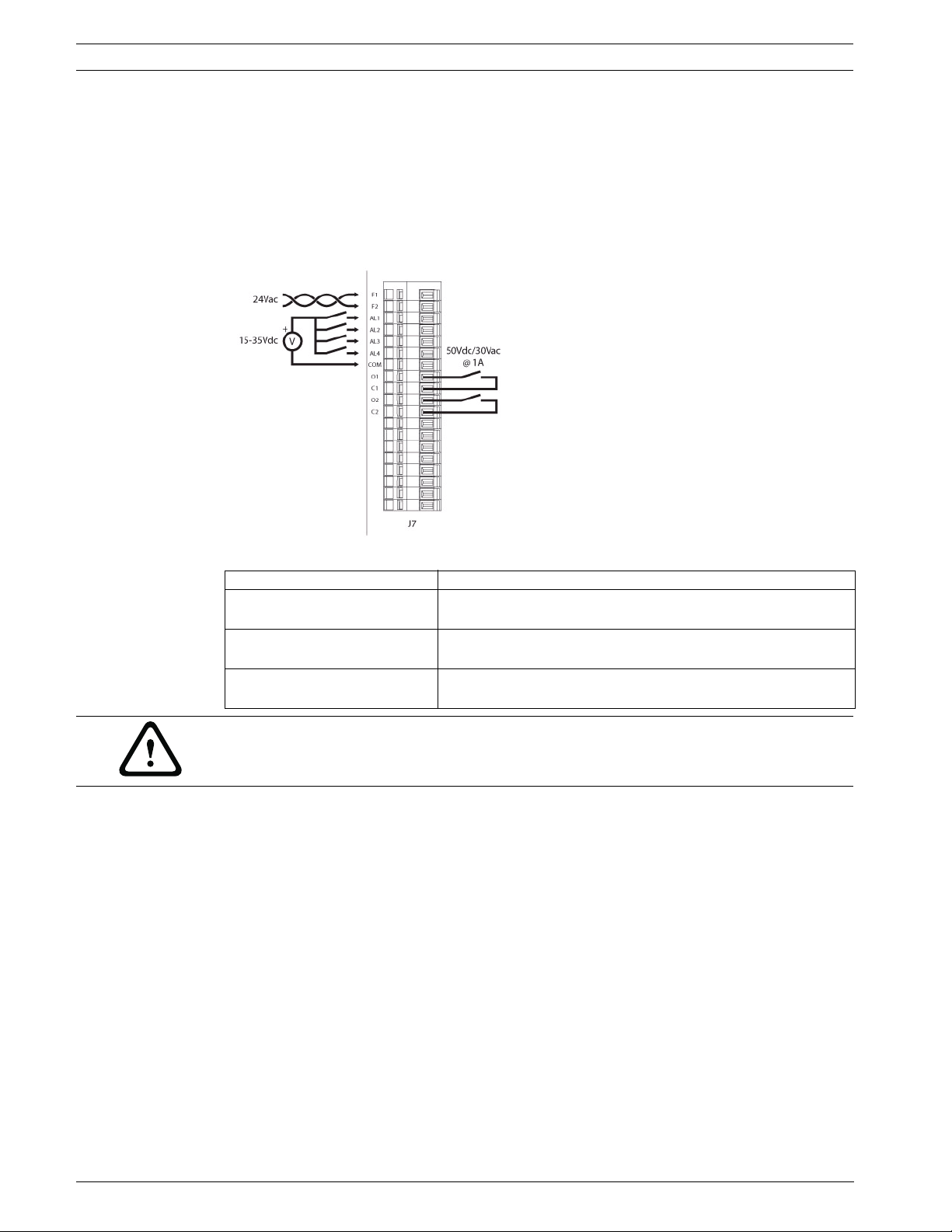
The standard base has a 19-pin connector for which the following connections are illustrated:
Figure 5.1 Base with 19-pin Connector for Connecting Peripherals
Reference Description
F1 and F2 Feed 1, 24 VAC for optional washer; Feed 2, 24 VAC for
optional washer
O1-C1 and O2-C2
(O=Output, C=Common)
AL1, AL2, AL3, and AL4, COM Alarm inputs 1-4, voltage-controlled (10-35 VDC supplied
CAUTION!
The system is TNV-1 type, do not connect to SELV circuits.
Dry contact output that can be activated by alarm or by user
(50 VDC or 30 VAC @ 1A)
externally), referred to common COM
F.01U.164.491 | 2.0 | 2010.03 Installation Manual Bosch Security Systems, Inc.
Page 26
High-speed Positioning System Connecting the Peripherals | en 27
5.2 Connecting to the IR360 Base
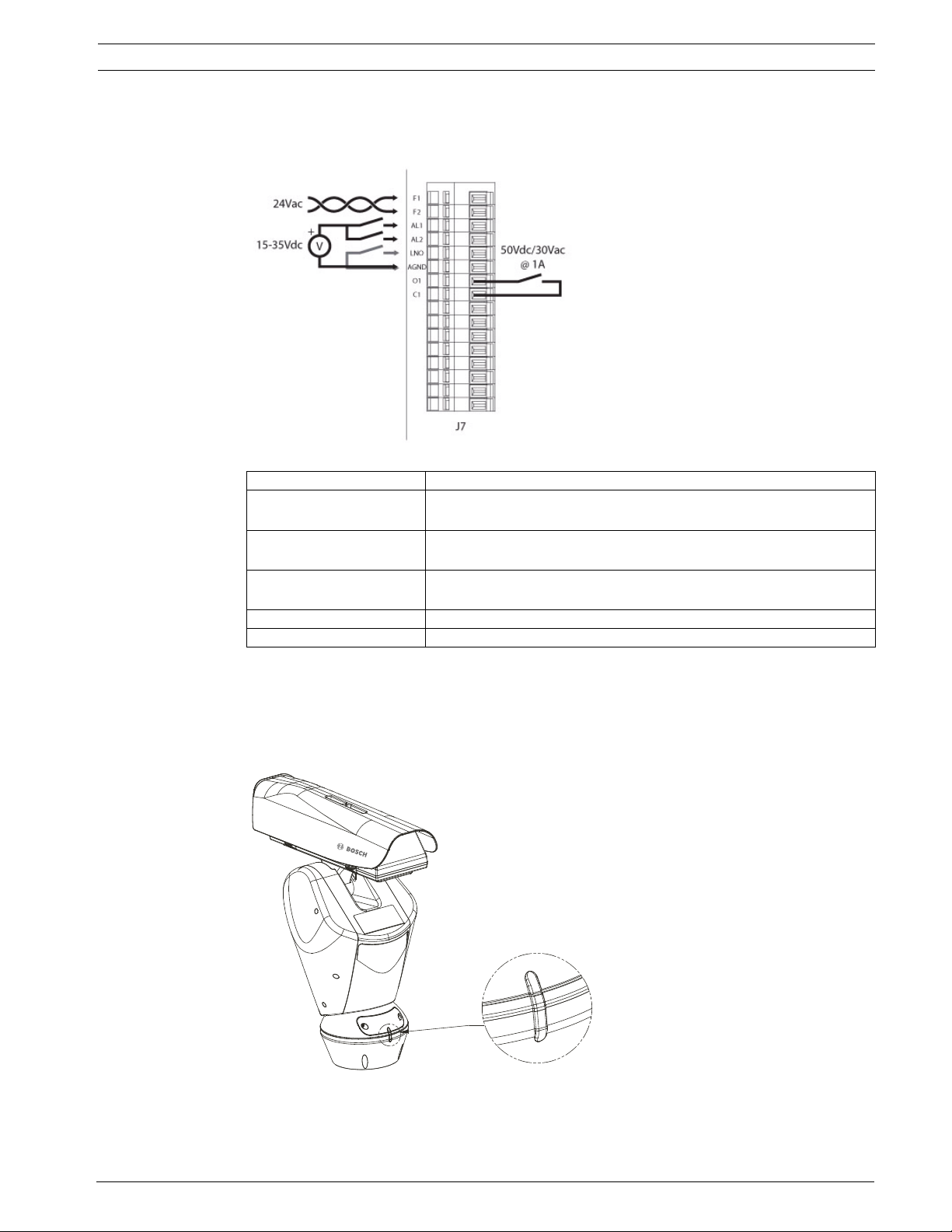
The IR360 base has a 16-pin connector for which the following connections are illustrated:
Reference Description
F1 and F2 Feed 1, 24 VAC for optional washer; Feed 2, 24 VAC for optional
washer
O1 and C1
(O=Output, C=Common)
AL1 and AL2 Alarm inputs 1-2, voltage-controlled (10-35 VDC supplied
AGND Alarm Ground & External IR probe common
LNO External photosensor/IR probe
Dry contact output that can be activated by alarm or by user (50
VDC or 30 VAC @ 1A)
externally), referred to AGND
5.3 Fixing the Top Unit
Each time the top unit requires re-assembling, the screw seals should be replaced (use a
calibrated torque wrench setting of 2.1 Nm) to ensure the appliance remains water tight.
To attach the top of the unit to the base, do the following:
Figure 5.2 Aligning the Tabs
Bosch Security Systems, Inc. Installation Manual F.01U.164.491 | 2.0 | 2010.03
Page 27

28 en | Connecting the Peripherals High-speed Positioning System
1. Push down to snap into place.
2. Attach the top unit to the base using the supplied attachment screws and corresponding
seals.
3. Tighten the base with a 4 mm Allen wrench.
Figure 5.3 Attaching the Top Unit
Reference # Description
1 Configuration Window
2 Base
3Screw
4 Screw Seal
5Gasket
WARNING!
Place the provided safety label near unit that warns of moving parts.
F.01U.164.491 | 2.0 | 2010.03 Installation Manual Bosch Security Systems, Inc.
Page 28
High-speed Positioning System Connecting the Peripherals | en 29
5.4 IR360 Models (optional)
The device must be configured to mount two of the Bosch UFLED illuminators. The
illuminators are connected to the bracket supplied with the pan and tilt motor.
CAUTION!
For operational reasons, both spotlights must be fitted.
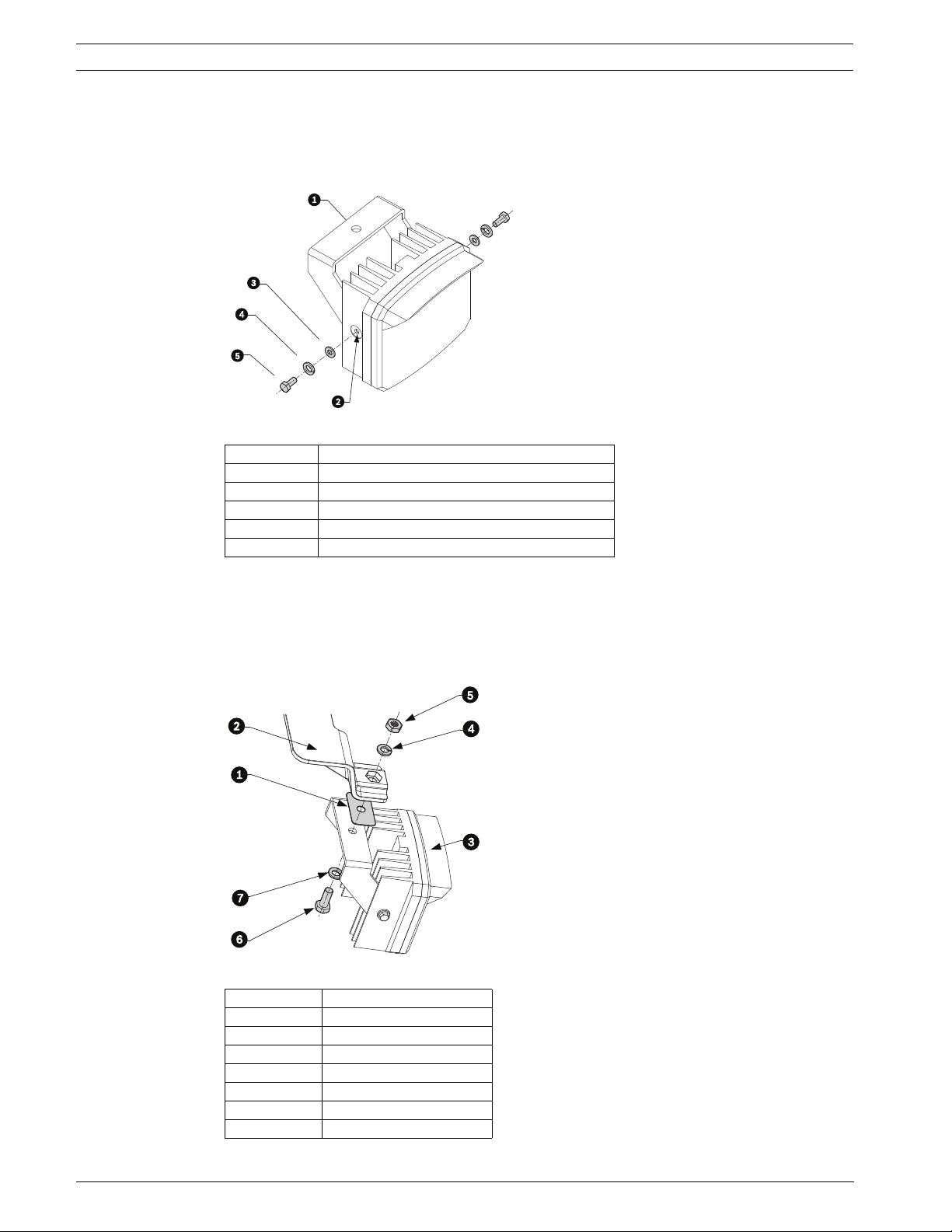
When turning on, the device looks for the angular reference.
5.4.1 Fitting the Bracket
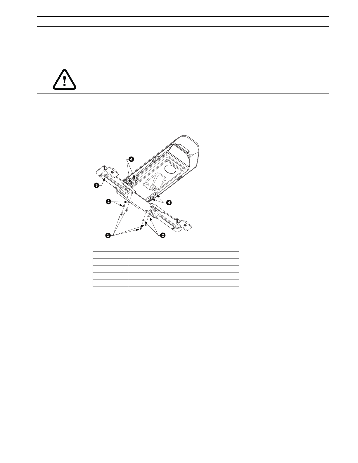
Position the bracket on the bottom of the housing as shown in the illustration. Insert the
screws with the washers into the respective holes and tighten. Make sure the bracket is
fastened down firmly. Use only the material suppled with the kit.
Figure 5.4 Fitting the Bracket
Reference Description
1Screws
2Washers
3Bracket
4Holes
Bosch Security Systems, Inc. Installation Manual F.01U.164.491 | 2.0 | 2010.03
Page 29
30 en | Connecting the Peripherals High-speed Positioning System
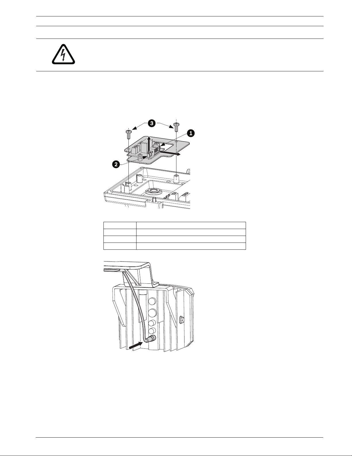
5.4.2 Assembling the Spotlights
Position the bracket so that the threaded holes are on the same axis as the holes on the body
of the spotlight. Fix the two components using the screw, the crinkle washer, and the plane
washer.
Figure 5.5 Assembling the Spotlight
Reference Description
1Bracket
2 Spotlight holes
3Plane washer
4Crinkle washer
5Screw
5.4.3 Fitting the Spotlight on the Bracket
Position the gasket between the bracket and the spotlight. Place the crinkle washer and the
nut in the respective hexagonal seat. Fix the assembly using the screw and it washer. Make
sure the spotlight is fastened firmly to the bracket. Complete the necessary wiring and
configure the on-screen menu to disable complete rotation of the pan and tilt.
Figure 5.6 Fitting the Spotlight on the Bracket
Reference Description
1Gasket
2Bracket
3Spotlight
4 Crinkle washer
5Nut
6Screw
7Washer
F.01U.164.491 | 2.0 | 2010.03 Installation Manual Bosch Security Systems, Inc.
Page 30
High-speed Positioning System Connecting the Peripherals | en 31
DANGER!
During normal operation, the surface of the spotlight can reach very high temperatures. Do
not allow direct contact. Ensure to position the product where it is inaccessible to
unauthorized persons.
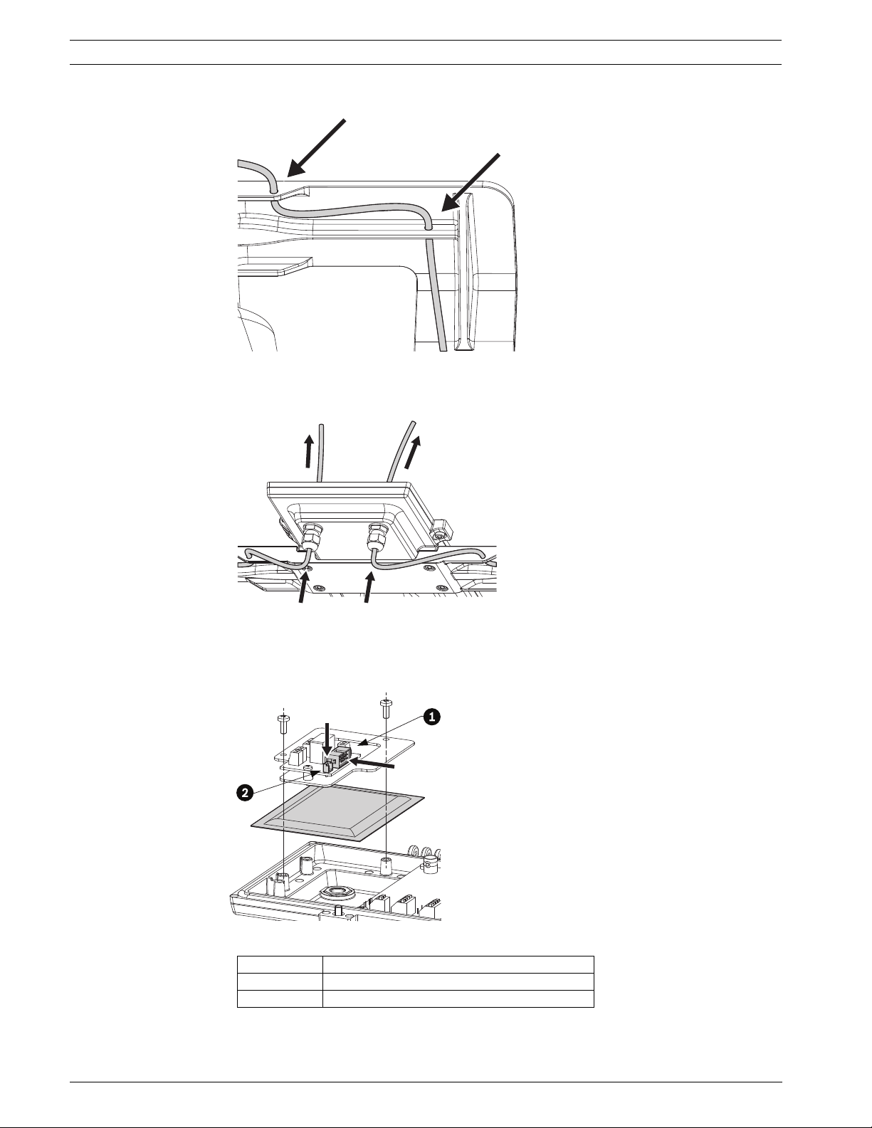
5.4.4 Infrared LED Spotlight Connections and Configurations
1. Open the housing.
2. Extract the support plate from the housing.
3. Disconnect the flat cable, disconnect the relay power supply connector, and remove the
screws.
Figure 5.7 LED Connections
Reference Description
1 Flat cable
2 Power supply connector
3Screws
4. Connect the power cable to the spotlight.
Figure 5.8 Connecting the Power Cable to the Spotlight
Bosch Security Systems, Inc. Installation Manual F.01U.164.491 | 2.0 | 2010.03
Page 31
32 en | Connecting the Peripherals High-speed Positioning System
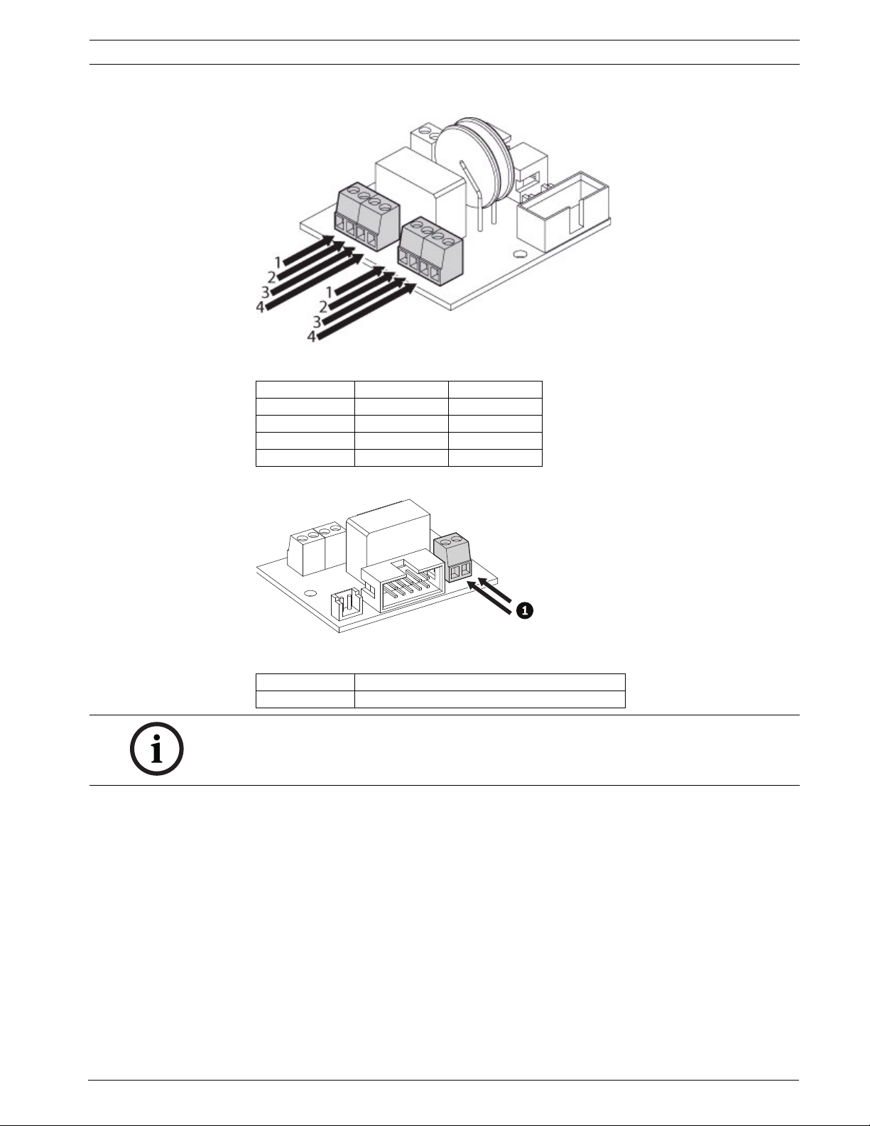
5. Thread the cable through the holes in the pan and tilt bracket.
Figure 5.9 Threading the Cable through the Bracket
6. Insert the cable in the cable glands mounted in the lower part of the housing so that they
protrude about 20 cm.
Figure 5.10 Inserting the Cable through the Cable Glands
7. Place the desiccant bag in the housing and fasten the support plate to the housing. To
complete the operation, it is necessary to connect the flat cable and the relay power
supply connector previously disconnected.
Figure 5.11 Inserting the Desiccant Bag
Reference Description
1 Flat cable
2 Relay power supply connector
F.01U.164.491 | 2.0 | 2010.03 Installation Manual Bosch Security Systems, Inc.
Page 32
High-speed Positioning System Connecting the Peripherals | en 33
8. Connect the cables as illustrated.
Figure 5.12 Connecting the IR Cables
Reference Color Description
1Brown24 VAC1
2White24 VAC1
3 Black 24 VAC2
4Blue24 VAC2
Figure 5.13 Switching Day and Night Mode
Reference Description
1Night Mode
NOTICE! The day/night mode relay is pre-wired. This drawing is for reference only. For more
information on how to operate the day/night mode, please call technical support 1-800-326-
1450.
Bosch Security Systems, Inc. Installation Manual F.01U.164.491 | 2.0 | 2010.03
Page 33
34 en | Configuring the Device High-speed Positioning System
6 Configuring the Device
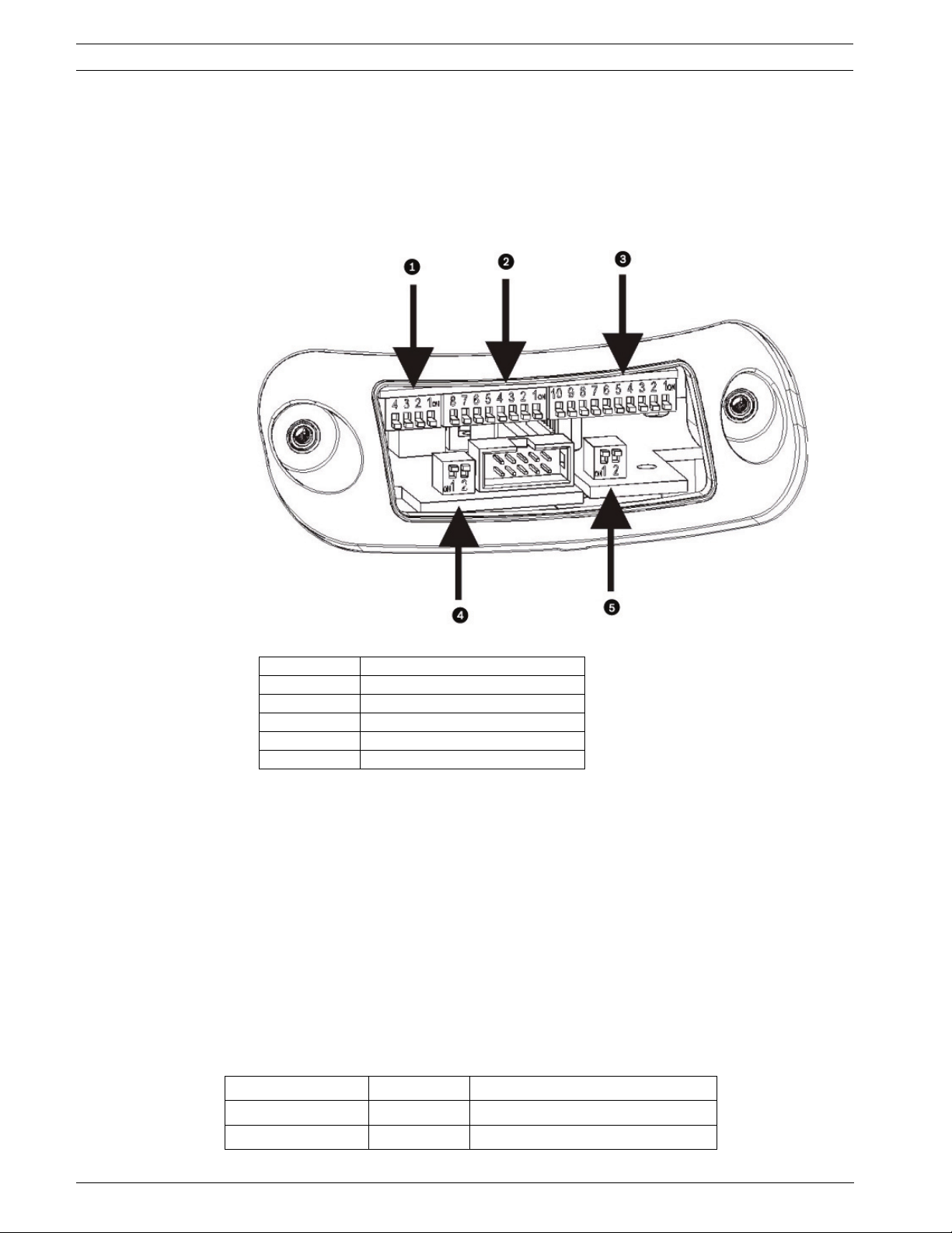
Before powering the High Speed Pan/Tilt, it must be properly configured. To configure the DIP
switches inside the configuration window, proceed as follows:
1. Open the configuration window (as seen in Figure 6.1) by unscrewing the screws with a
3 mm Allen wrench.
2. Verify that the position of the DIP switches are the same as inFigure 6.1.
Figure 6.1 Positioning the DIP Switches
Reference Description
1 Factory Use
2 Not Used, All Off
3Address
4 RS485 Terminations
5 Biphase + Bilinx
– For DIP switches (Reference 1-3 Figure 6.1), when the rocker is down the switch is OFF
or represents the logical value “0”; when the rocker is up, the switch is ON, with logical
value “1.”
– For DIP switches (Reference 4-5 Figure 6.1), when the rocker is up the switch is OFF or
represents the logical value “0”; when the rocker is down, the switch is ON, with logical
value “1.” The white rectangle represents the position of the rocker.
6.1 Factory Use Only
Leave all switches in the OFF position.
6.2 Protocol
There is no need to set any particular protocol, the UPH is auto-sensing. The protocols
supported are:
Protocol Baud Rate Menu Setup (OSD)
Pelco D 2400 (8N 1) Preset 95
Biphase and Bilinx Auto AUX-On 200
F.01U.164.491 | 2.0 | 2010.03 Installation Manual Bosch Security Systems, Inc.
Page 34
High-speed Positioning System Configuring the Device | en 35
6.3 Setting the Address
You can set the address for the UPH address using the Address switched (see item 3 in
Figure 6.1).
NOTICE! The highest addres using the Bosch OSRD protocol is 998. The highest address
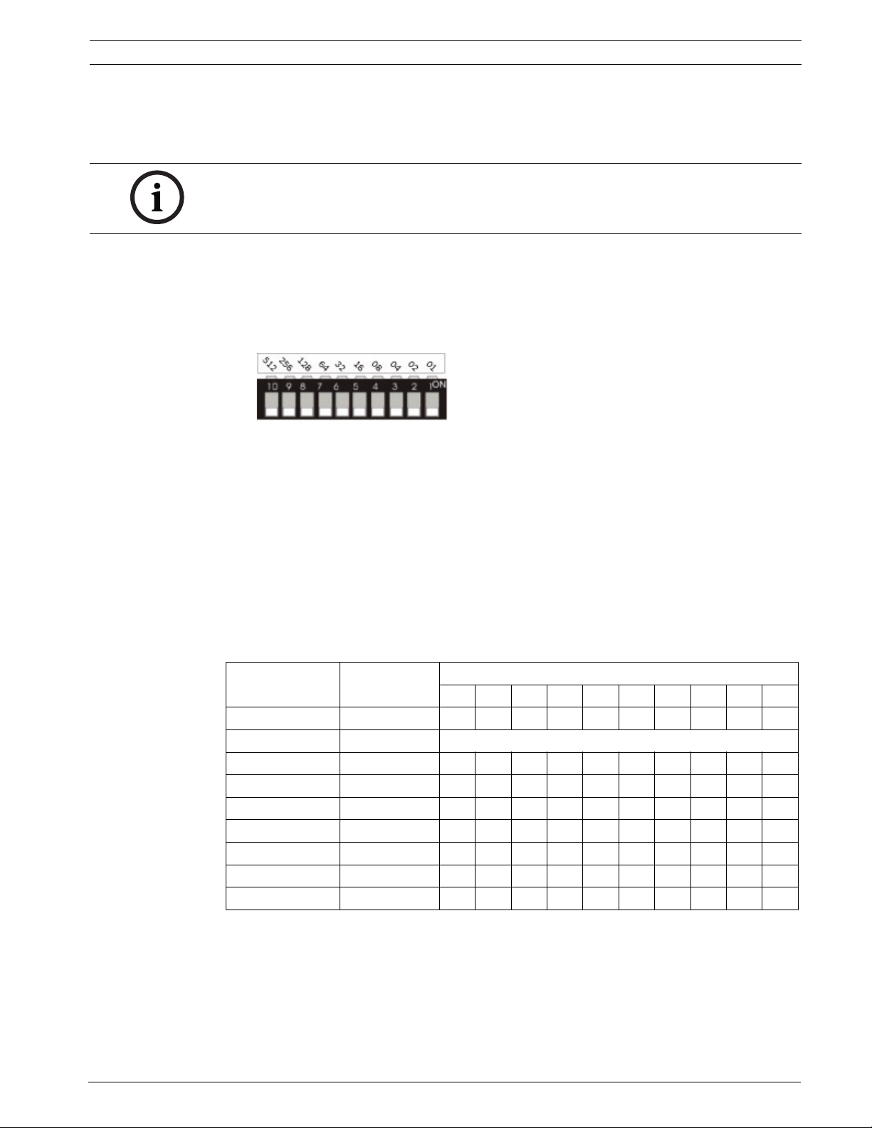
using the Pelco D protocol is 255.
Binary code is used to select the address using the 10 DIP switches. The up position
represents binary value “1”, while the down position represents binary value “0”.
To convert a decimal address to a binary address, use the following technique.
– Assign a binary value to each DIP switch, starting with a binary value of “1” for DIP switch
1. If the DIP switch is “on” then the number associated with the switch is stored.
– Consider the decimal address and start adding the DIP switch values from the left,
skipping a DIP switch value that is higher than the decimal address.
– Turn a DIP switch to “on” if its associated value is used for the address. Keep the DIP
switch “off” if its associated value is too high or is not needed to add up to the decimal
address.
For example, to convert the decimal address 237 to binary:
Flag each binary digit needed to add up to 237 starting from the left. Do not flag 512 and 256
since these values are larger than 237. The first binary value to flag is 128; then flag 64 and 32
adding up to 224. Do not flag 16 because that puts the decimal value over 237. The next digit
to flag is 8, then skip 4 (too large), and flag the 2 and 1. The flagged numbers should equal
237: 128+64+32+8+2+1=237.
The following table lists DIP switch positions for various decimal addresses:
Decimal Address Binary Value
1 1 OFF OFF OFF OFF OFF OFF OFF OFF OFF ON
2 10 OFF OFF OFF OFF OFF OFF OFF OFF ON OFF
4 100 OFF OFF OFF OFF OFF OFF ON OFF OFF OFF
8 1000 OFF OFF OFF OFF OFF OFF ON OFF OFF OFF
143 1000 1111 OFF OFF ON OFF OFF OFF ON ON ON ON
299 1 0010 1011 OFF ON OFF OFF ON OFF ON OFF ON ON
998 11 1110 0110 ON ON ON ON ON OFF OFF ON ON OFF
6.4 RS485 Line Termination
Serial Lines Termination Switches (refer to item 4 in Figure 6.1):
– Dip-switch 1 is not used (the RS485-1 line is not available).
– Dip-switch 2 is used to enable the line termination of RS485-2 serial line (Pelco D only).
– Down/On = terminated
– Up/Off = Open
DIP Switch Positions
10987654321
5122561286432168421
Bosch Security Systems, Inc. Installation Manual F.01U.164.491 | 2.0 | 2010.03
Page 35
36 en | Configuring the Device High-speed Positioning System
6.5 Biphase/Bilinx Termination
Bilinx and Biphase Switches (refer to item 5 in Figure 6.1):
– Dip-switch 1 is used to enable the line termination of a Biphase serial line.
– Down/ON = terminated. Up/OFF = open (daisy chain).
– Dip-switch 2 is used to select the video format (Down/ON = PAL, Up/OFF = NTSC).
6.6 Connections
All versions support Bilinx and Biphase telemetry control, i.e.: PTZ.
The PTZ menu setup of UPH Series is done via the AUX ON - 200 - Enter. The camera menu
setup is done via two different AUX commands, i.e.: AUX ON - 46 - Enter (Dinion main menu)
and AUX ON - 801 - Enter (Dinion installation menu). See 9 Keyboard Commands List - Bosch
for more information about keyboard commands.
Bilinx is a Bosch two-way communication protocol that allows remote control, configuration,
and updates over a video coax cable. Bilinx is available on all UPH models.
Biphase is used for communicating telemetry (control) and set up information with the
UPH-Series units over a shielded twisted pair. Biphase does not pass the video signal from the
UPH-Series units, so a separate video coax cable is required. Biphase should be wired with
Belden 8760 or equivalent. Biphase is available on all UPH models.
Note: If the UPH is the only Biphase unit connected, or the last unit in a daisy chain
configuration, then turn ON dip-switch 1 of Biphase + Bilinx to terminate the data line. Turn
OFF dip-switch 1 of Biphase + Bilinx for each UPH in a daisy chain (i.e. unterminated). A
maximum of four (4) UPH units can be daisy chained together.
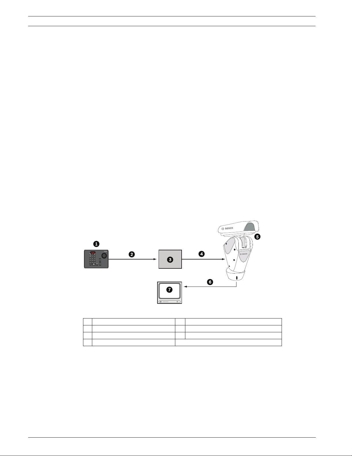
Figure 6.2 Typical Setup via an Interface Box
1 LTC 5136 or equivalent 5 UPH Series: unitized pan/tilt head
2 RS-232 6 Video out, coax
3 LTC 8786 7 CCTV Monitor
4Biphase
F.01U.164.491 | 2.0 | 2010.03 Installation Manual Bosch Security Systems, Inc.
Page 36
High-speed Positioning System Configuring the Device | en 37
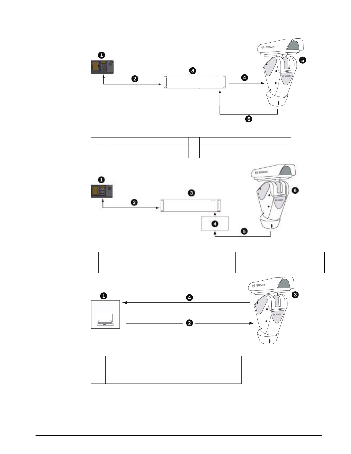
Figure 6.3 Typical Setup via an Allegiant with Biphase
1 IntuiKey Keyboard 4 Biphase
2 RS-485 5 UPH Series: unitized pan/tilt head
3 Allegiant Matrix Switcher 6 Video out, coax
Figure 6.4 Typical Setup via an Allegiant + LTC 8016
1 IntuiKey Keyboard 4 LTC 8016 Bilinx Data Interface
2 RS-485 5 Bilinx/Video
3 Allegiant Matrix Switcher 6 UPH Series: unitized pan/tilt head
Figure 6.5 Typ ical Co n nectio n s to a DiBos
1DiBos 8
2Biphase
3 UPH Series: unitized pan/tilt head
4 Video output coax
Bosch Security Systems, Inc. Installation Manual F.01U.164.491 | 2.0 | 2010.03
Page 37
38 en | Configuring the Device High-speed Positioning System
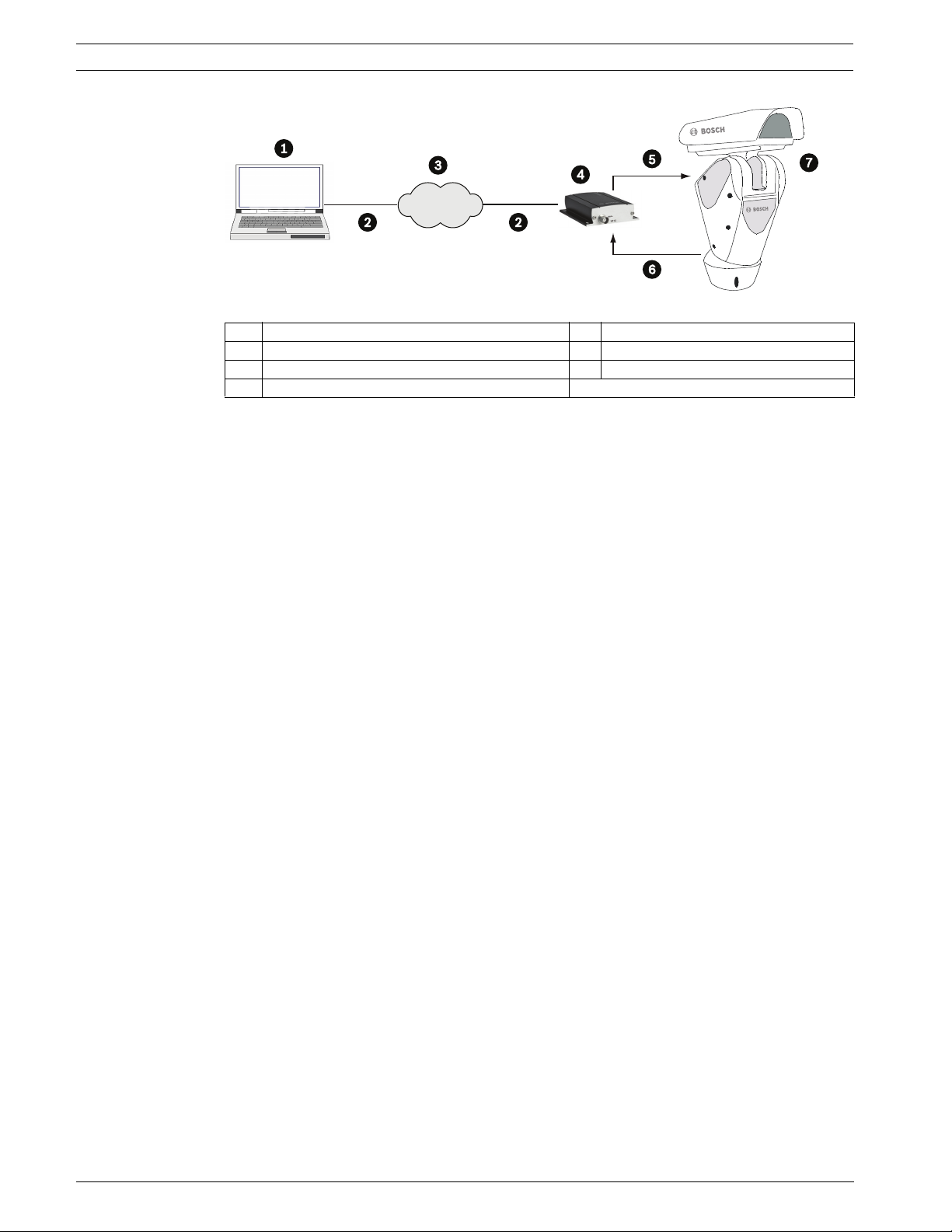
Figure 6.6 VIPX1 Connection Diagrams
1 Vidos, IE, DiBos 8, Bosch VMS or equivalent 5 RS-485-2
2Ethernet 6Video
3 LAN 7 UPH Series: unitized pan/tilt head
4VIP X1
F.01U.164.491 | 2.0 | 2010.03 Installation Manual Bosch Security Systems, Inc.
Page 38
High-speed Positioning System On-screen Display (OSD) | en 39
7 On-screen Display (OSD)
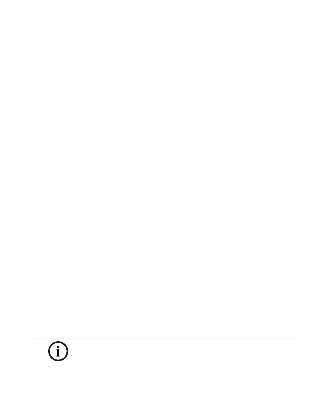
During normal UPH operation, it is possible to activate the on-screen menu in order to set the
advanced functions using the corresponding key/s.
Each on-screen display (OSD) shows a list of parameters or submenus that can be selected by
the operator. For example, to access the main menu in the High Speed Pan/Tilt, click AUX -
ON - 200 then Enter. If the camera is a Dinion
accessed by clicking AUX - ON - 46, then Enter. The Dinion
by clicking AUX - ON - 801 then Enter.
1. To scroll through the parameters, move the cursor by operating the joystick up and
down.
– To scroll through the parameters, move the cursor by operating the joystick up or
down.
– The cursor is indicated by the “”” symbol at the beginning of a line, i.e. on the left
side of the screen/monitor.
2. The “>” symbol at the end of a line, i.e. on the on the right of the screen/monitor,
indicates the presence of a submenu. To enter the submenu, confirm the menu item by
pressing the Focus Near or Far key.
3. To exit the submenu, press Iris Open or Iris Close button.
XF
option, then the DinionXF’s main menu can be
XF
’s Installer menu can be accessed
MAIN MENU
1 - LANGUAGE >
> 2 - DISPLAY SETUP >
3 - MOTION PARAMETERS >
4 - CAMERA PARAMETERS >
5 - LOAD DEFAULT CONFIG >
6 - SETUP INFO >
Tab le 7 .1 Accessing the Main Menu - AUX On 200
MODE
ALC 2
ENHANCE
COLOR
BLC OFF
VMD OSD
MODE ID TRAFFIC
DEFAULTS
EXIT
Tab le 7 .2 Accessing the DinionXF camera Setup Menu - AUX On 46 (screen may differ depending on
the camera type)
NOTICE!
Based on the model you are using, on-screen menus may vary slightly.
Bosch Security Systems, Inc. Installation Manual F.01U.164.491 | 2.0 | 2010.03
Page 39

40 en | Configuring the System High-speed Positioning System
8 Configuring the System
The UPH High Speed Pan/Tilt can be configured through the on-screen display (OSD). Open
the main menu by pressing AUX ON - 200 - Enter. Use the joystick to move up and down
through the menus. Press focus to select the sub-menu.
MAIN MENU
1 - LANGUAGE >
2 - DISPLAY SETUP >
3 - CAMERA PARAMETERS >
4 - LENS PARAMETERS >
5 - LOAD DEFAULT CONFIG. >
6 - SETUP INFO >
8.1 Language Menu
This menu is used to select and set the desired language. The default setting is English.
LANGUAGE MENU
1 - ITALIANO
>2 - ENGLISH OK
3 - FRANCAIS
4 - DEUTSCH
Tab le 8 .1 Language Menu with English Selected
8.2 Display Setup Menu
The Display Setup menu is used to define settings for the information that is permanently
displayed on the screen.
DISPLAY SETUP MENU
> 1 - PAN/TILT POSITION : YES
2 - PRESET TITLE : YES
3 - PRESET POSITION : YES
4 - TILT LIMIT TITLE : YES
5 - VIDEO SIGNAL : PAL
6 - INTERLACED VIDEO : YES
7 - AREA PARAMETERS >
8 - DISPLAY PARAMETERS >
Tab le 8 .2 Display Setup Menu
F.01U.164.491 | 2.0 | 2010.03 Installation Manual Bosch Security Systems, Inc.
Page 40

High-speed Positioning System Configuring the System | en 41
Feature Description Default Options
PAN/TILT
POSITION
Shows the current position of the device (in
degrees) with reference to the home position.
YES YES, NO
PRESET TITLE Enables or disables the preset title on the display. YES YES, NO
PRESET POSITION Enables or disables the preset number reached
YES YES, NO
on the display.
TILT LIMIT TITLE Enables or disables displaying if the tilt limit is
YES YES, NO
reached.
VIDEO SIGNAL Type of video signal. Select to automatically
adjust position of OSD.
INTERLACED
VIDEO
AREA PARAMETERS
(sectors)
DISPLAY
PARAMETERS
Enables or disables the display for interlaced
video.
Information about area (or sector) that the unit is
pointing towards.
Setup of location of text position/type on the
display.
PAL PAL,
NTSC
YES YES, NO
8.2.1 Area Parameters Menu
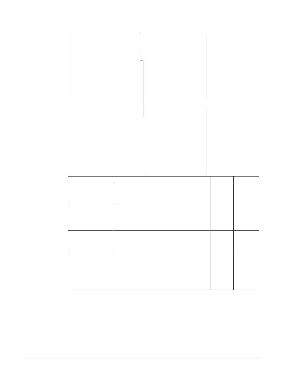
The Area Parameters menu enables the user to show a message on the screen, depending on
the horizontal position reached by the device; this is sometimes known as sector information.
From this menu, it is possible to enter two (2) lower menus that are used to set the text for
each area, and the start and end positions (in degrees) of these areas. It is possible to set up
to eight (8) areas with their own title, start, and end positions.
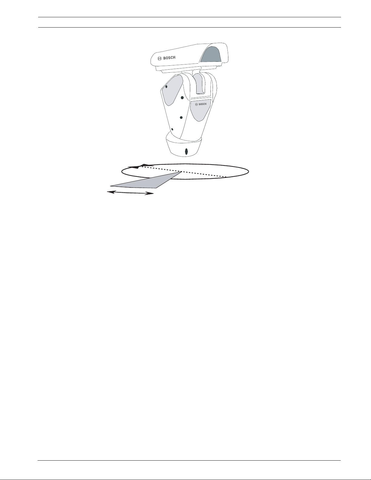
For example, to activate the first title and obtain a message when the device is between +80 °
and +120 ° in the horizontal (pan) direction, proceed as follows:
1. Enter the Position Area menu.
2. Select Area 1 by pressing Focus; an arrow starts blinking next to the start position. Press
Focus again, use the joystick to enter the value +080.00 in the left column (start position
of text coming on screen), then press Focus to store that value. Repeat the process, but
put +120.00 in the right column (stop position of text removed from the screen).
3. In the Text (String) Area menu, select the first line and enter the desired text.
Note! If the area position start and end values are set to +0.00, this disables the text
display (defaults are all set to +0.00).
Bosch Security Systems, Inc. Installation Manual F.01U.164.491 | 2.0 | 2010.03
Page 41
42 en | Configuring the System High-speed Positioning System
AREA PARAMETERS MENU TEXT AREA MENU
1 - AREAS TITLE : NO > 1 - AREA 1
2 -STRING AREA MENU > 2 - AREA 2
3 - POISTION AREA MENU > 3 - AREA 3
4 - AREA 4
5 - AREA 5
6 - AREA 6
7 - AREA 7
8 - OFFSET PAN: + 0.0 8 - AREA 8
Test area 1
AREA POSITION MENU
> 1 - AREA 1 + 0.0 + 0.0
2 - AREA 2 + 0.0 + 0.0
3 - AREA 3 + 0.0 + 0.0
4 - AREA 4 + 0.0 + 0.0
5 - AREA 5 + 0.0 + 0.0
6 - AREA 6 + 0.0 + 0.0
7 - AREA 7 + 0.0 + 0.0
8 - AREA 8 + 0.0 + 0.0
Test area 1
Feature Description Default Options
AREA TITLE Enables / disables the on-screen message
NO YES, NO
depending on the horizontal position reached
by the device.
STRING AREA MENU Enables the user to edit a customized, on-
screen text message that is activated when
N/A Area 1 to
Area 8
the device reaches a defined, horizontal
position.
POSITION AREA
MENU
The horizontal position reached by the device
that prompts a customized on-screen text
N/A Area 1 to
Area 8
message.
OFFSET PAN Adds a corresponding value (offset) in
degrees to the pan references used for
displaying the area text. For example, if this
+0.00 -
180.00to+
180.00
value is set to +45.0 ° then all references will
be shifted in PAN by +45 ° with respect to the
system’s physical reference.
Tab le 8 .3 Area Parameters Menu
F.01U.164.491 | 2.0 | 2010.03 Installation Manual Bosch Security Systems, Inc.
Page 42
High-speed Positioning System Configuring the System | en 43
+/-180°
0°
120°
Figure 8.1 Setting the Area Position Values
80°
8.2.2 Changing the Edit Text Menu
To change the text within the Edit Text menu, proceed as follows:
1. Upon accessing the Edit Text menu, select String Edit. The first field flashes a “v”,
indicating it is in Edit mode.
2. Press the Focus button. The cursor flashes at the bottom of the screen, corresponding to
the groups of alpha/numeric characters. Operate the joystick (up, down, left, and right)
to select a group of characters.
3. Press the confirmation (Focus) button to confirm the alpha/numeric group containing
the character to be added. The first value in the sequence you selected starts flashing.
4. Move the joystick up or down to choose a value.
5. When finished, press the Focus button to confirm your choice. The “v” automatically
moves to the right.
6. Repeat steps 2-5 until finished.
7. When finished, press the Iris button to exit the menu.
Note: To skip a space while in edit mode, press the Iris button, then move the joystick to the
right past the number spaces you would like to skip. Press the Focus button to resume adding
values.
Bosch Security Systems, Inc. Installation Manual F.01U.164.491 | 2.0 | 2010.03
Page 43

44 en | Configuring the System High-speed Positioning System
The character being edited flashes and the joystick (up and down) can be used to change it.
After making the change, confirm and continue to edit the text, or else exit with the Iris
button.
EDIT TEXT MENU
v _ _ _ _ _ _ _ _ _ _ _ _ _ _ _ _ _ _ _ _
> 1ABC 2DEF 3GHI 4JKL
5MNO 6PQR 7STU 8VWX
9YZ 0()x +,-.
Tab le 8 .4 Edit Text Menu
Offset Pan
By default, the offset pan is +0.00. The value can be changed to move the default pan position
of the unit to wherever is convenient. For example, if the installation requires that the NORTH
position should be at 0.00 ° (pan), then an offset pan can be entered to compensate for any
deviation from NORTH. After mounting, the NORTH position was found to be +41.37 ° (pan
position); therefore, the offset pan should be set to - 41.37 ° to make the pan +0.00 ° position
point to NORTH.
This has an effect on the Area Titles as defined in the Area Position menu. In the above
example, after the offset pan has been set to -41.37 °, the Area Text Menu “1 - Area” could be
changed to “1 - NORTH” to display NORTH on the screen at pan +0.00 ° position.
8.2.3 Display Parameters
The Display Parameters menu is used to enter the settings menus for the device movement
parameters.
DISPLAY PARAMETERS
> 1 - OSD VIDEO ENABLING : YES
2 - VIDEO CHARACTER TYPE : 000
3 - HORIZONTAL DELTA : 000
4 - VERTICAL DELTA : 000
5 - ADDRSS NR. YES
F.01U.164.491 | 2.0 | 2010.03 Installation Manual Bosch Security Systems, Inc.
Page 44

High-speed Positioning System Configuring the System | en 45
OSD Video Enabling Set to YES to superimpose the menu text over the video signal
from the camera. Set to NO to have a blue screen behind the
menu TEXT.
Video Character Type Set to 0 to make the background of the text to transparent; set to
1 to make it black.
Horizontal Delta/Vertical
Delta
Address Number If enabled, the address number of the unit is shown at the top left
These set the position of reference to the title so that the text can
be centralized. 0 (left, up) and 6 (right, down).
of the screen during normal operation. Yes/No.
8.3 Motion Parameters Menu
The Motion Parameters menu is used to control the speed, limits, preset/patrol/autopan,
wiper-washer, and the alarm settings of the UPH.
MOTION PARAMETERS MENU
> 1 - SPEEDS >
2 - LIMITS >
3 - PRESET/PATROL/AUTOPAN >
4 - WIPER-WASHER >
5 - ALARMS >
8.3.1 Speed Menu
The Speed menu is used to control the pan and tilt movement of the UPH in manual control
mode using the joystick. See Section 8.3.1 Speed Menu, page 45 for setting pan and tilt speeds
for the presets, patrols, and scans.
SPEED MENU > 1 - SPEED 1... 1.0 gr./s
> 1 - PAN SPEED > 2 - SPEED 2... 2.0 gr./s
2 - TILT SPEED > 3 - SPEED 3... 5.0 gr./s
3 - ZOOM DEPENDENT SPEED :NO 4 - SPEED 4... 10.0 gr./s
SPEED MENU - PAN
5 - SPEED 5... 20.0 gr./s
6 - SPEED 6... 30.0 gr./s
7 - SPEED 7... 40.0 gr./s
8 - DEFAULT
SPEED MENU - TILT
" 1 - SPEED 1... 1.0 gr./s
2 - SPEED 2... 2.0 gr./s
3 - SPEED 3... 3.0 gr./s
4 - SPEED 4... 5.0 gr./s
5 - SPEED 5... 8.0 gr./s
6 - SPEED 6... 10.0 gr./s
7 - SPEED 7... 20.0 gr./s
8 - DEFAULT
Bosch Security Systems, Inc. Installation Manual F.01U.164.491 | 2.0 | 2010.03
Page 45
46 en | Configuring the System High-speed Positioning System
Feature Description Default Options
PAN SPEED 1 Correspondence between
PAN SPEED 2 2.0 0.1-100.0
PAN SPEED 3 5.0 0.1-100.0
PAN SPEED 4 10.0 0.1-100.0
PAN SPEED 5 20.0 0.1-100.0
PAN SPEED 6 30.0 0.1-100.0
PAN SPEED 7 40.0 0.1-100.0
joystick position and UPH
speed. Joystick positions
have been divided into 7
levels for both axis (pan &
tilt); each level corresponds
to a defined speed which can
be modified by the user.
1.0 0.1-100.0*
Note: *IR models are limited to 40 deg/s on pan
Feature Description Default Options
TILT SPEED 1 Correspondence between
TILT SPEED 2 2.0 0.1-40.0
TILT SPEED 3 3.0 0.1-40.0
TILT SPEED 4 5.0 0.1-40.0
TILT SPEED 5 8.0 0.1-40.0
TILT SPEED 6 10.0 0.1-40.0
TILT SPEED 7 20.0 0.1-40.0
joystick position and UPH
speed. Joystick positions
have been divided into 7
levels for both axis (pan &
tilt); each level corresponds
to a defined speed which can
be modified by the user.
1.0 0.1-40.0*
Note: *IR models are limited to 30 deg/s on tilt
The data is expressed as degrees per second.
Zoom dependent speed by default is turned off. When the zoom-dependent function is turned
off, then the pan and tilt speeds of the UPH are unaffected by the zoom measurement of the
camera/lens combination. If the zoom-dependent function is turned on, the zoom
measurement of the camera/lens combination affects the pan and tilt speeds. This is useful
when the zoom is in telephoto (i.e. zoomed in); it slows down the pan and tilt speeds so that
very fine adjustments can be made to follow moving subjects.
8.3.2 Limits
The Limits menu sets the movement limits for the UPH. These limits apply to all presets,
autopan and patrols, including manual operation of the UPH using the joystick. After the limits
are set in the OSD and the UPH moves into the “limited pan and tilt zone”, it will not move
outside of those limits until they are altered in the OSD or the UPH is reset. On reset, the UPH
returns to within the limited pan and tilt zone.
LIMITS MENU
> 1 - ENABLE PAN LIM. : NO
2 - START PAN : + 0.00
3 - END PAN : + 0.00
4 - ENABLE TILT LIM. : NO
5 - START TILT : + 0.00
6 - END TILT : + 0.00
9 - RAMP TYPE : 012
F.01U.164.491 | 2.0 | 2010.03 Installation Manual Bosch Security Systems, Inc.
Page 46
High-speed Positioning System Configuring the System | en 47
Feature Description Default Options
ENABLE PAN LIM. Enables limits and values in degrees
NO YES, NO
taken by the device in pan.
Enables or disables complete rotation
for scan/patrol/autopan movements
(this function is useful when using
accessories with external cables, such
as infrared spotlights, where continuous
rotation of the UPH could break the
accessories themselves).
START PAN Enables the location that the UPH
begins to pan.
END PAN Enables the location that the UPH stops
panning.
ENABLE TILT LIM. Enables limits and values in degrees
+0.00 -180.00° to
+180.00°
+0.00 -180.00° to
+180.00°
NO YES, NO
taken by the device in tilt.
START TILT Enables the location that the UPH
+0.00 -40.00° to +90.00°
begins to tilt.
END TILT Enables the location that the UPH stops
+0.00 -40.00° to +90.00°
tilting.
RAMP TYPE Changes start and stop times for the
012 000 to 012
UPH. The higher the number, the
greater the acceleration/deceleration
during starting/stopping.
8.3.3 Preset/Patrol/Autopan
The Preset/Patrol/Autopan menu sets the movement limits related to the UPH.
MOTION PARAMETERS MENU
> 1 - PRESET >
2 - SPECIAL PRESET PARAM. >
3 - HOME POSITION >
4 - PATROL >
5 - AUTOPAN >
8 - MOTIONS RECALL >
Feature Description
PRESET A pre-selected and stored combination of pan, tilt and
SPECIAL PRESET PARAMETER Allows change to the default values for preset speeds and
HOME POSITION A special preset that is automatically recalled after an
PATROL Manually change the path of the automatic cycle between
zoom positions that allow a set view to be recalled.
forces it into all presets.
interval of time (see other confide. menu).
preset positions.
Bosch Security Systems, Inc. Installation Manual F.01U.164.491 | 2.0 | 2010.03
Page 47
48 en | Configuring the System High-speed Positioning System
Feature Description
AUTOPAN The camera pans continuously between right and left limit
settings.
MOTIONS RECALL Allows definition of action after an interval of inactivity (it
can recall a patrol, autopan, home position, etc).
Preset Menu
The Preset menu displays and allows changes to all parameters for the available preset
positions in the UPH. Use the up and down function of the joystick to move between the
presets in units, i.e.: PRST 01 to PRST 02 to PRST 03. Use the left and right function of the
joystick to move between the presets in tens, i.e.: PRST 01 to PRST 11 to PRST 21. Press
Focus to edit the chosen preset, using the joystick and Focus button to fine tune these
parameters. Use the Iris button to exit.
PRESET EDIT MENU
PRST PAN : + 0.0
01 TILT : + 0.0
ENABLE : NO
ZOOM : 00000
FOCUS : 00000
IRIS : 00000
SPEED : 040.0
DWELL : 00001
TXT: PRESET 001
Feature Description Default Options
PAN Moves a camera on a horizontal axis. 0.0 -180.00° to
+180.00°
TILT Moves a camera on a vertical axis. 0.0 -40.00° to +90.00°
ENABLE Enables preset. NO YES, NO
ZOOM Changing the effective focal length to
00000 65535
allow different fields of view to fill
the picture area. Zoom can be
optical, where the lens is adjusted, or
digital, where a portion of the view
selected is magnified electronically.
FOCUS Positions 00000 65535
IRIS Positions 00000 65535
SPEED Speed for reaching the position when
040.0 .1 to 100.0°*
the preset position is loaded by the
patrol function (preset tour).
DWELL Dwell time during patrol and autopan
movements.
00001 00000 to 01000
sec.
TXT: PRESET Message displayed when the preset
position is reached.
Note: *IR models are limited to 40 deg/s on pan
F.01U.164.491 | 2.0 | 2010.03 Installation Manual Bosch Security Systems, Inc.
Page 48

High-speed Positioning System Configuring the System | en 49
Special Preset Parameters
The Special Preset Parameters menu can be used to make parameter settings. Increase the
default value to increase the speed between presets or the scan speed.
SPECIAL PRESET PARAMETER MENU
> 1 - PRESET SPEED REF. : 20.0
2 - SCAN SPEED : 20.0
3 - TILT SPEED REDUCTION : 100
6 - PRESET DWELL TIME :00005
7 - FORCE PRST DW.TIME :NO
8 - FORCE PRST SPEED :NO
Tab le 8 .5 Special Preset Parameters
Feature Description Default Options
PRESET SPEED REF. Default value whenever a preset
20.0 0.1 to 100.0*
position is stored.
SCAN SPEED Reference speed used when a preset
20.0 0.1 to 100.0*
position is recalled by the shot
command.
TILT SPEED REDUCTION Tilt speed reducing factor with
100.0 0.1 to 100.0
respect to pan speed.
PRESET DWELL TIME Time in seconds to dwell at preset
position.
FORCE PRST DW.TIME Forces the default dwell time value
00005 00001 to
01000
NO YES, NO
for all presets.
FORCE PRST SPEED Forces the default speed value for all
NO YES, NO
presets.
Note: *IR models are limited to 40 deg/s on pan
Home Position
The Home Position menu is one of the 250 presets which can be defined as a preset position.
Please note that through the normal Set Shot Command, only 99 presets can be stored. Use
this menu for presets 100 to 250.
MENU HOME
> 1 - HOME POSITION : 00001
2 - REACHED SPEED : 20.0
Bosch Security Systems, Inc. Installation Manual F.01U.164.491 | 2.0 | 2010.03
Page 49

50 en | Configuring the System High-speed Positioning System
Feature Description Default Options
HOME POSITION Preset position associated with the home
00001 00001 to 00250
function.
REACHED SPEED Speed for reaching the home position
20.0 .1 to 100.0*
when it is loaded.
Note! Increase the reached speed from the default value to reach presets faster.
Note: *IR models are limited to 40 deg/s on pan
Patrol (preset tour)
The Patrol menu is a defined path from preset to preset. This can be from two (2) presets up
to 250. For example, the random option allows various presets such as preset 4, then
preset 1, then preset 8, then preset 3.
PATROL MENU
> 1 - START POSITION : 00001
2 - END POSITION : 00250
3 - FIRST PRST SPEED : 20.0
4 - RANDOM : NO
Feature Description Default Options
START POSITION The first preset position considered valid
00001 00001 to 00250
for carrying out the patrol function.
END POSITION The last preset position considered valid
00250 00001 to 00250
for carrying out the patrol function.
FIRST PRST SPEED Speed at which the UPH reaches the first
20.0 01 to 100.0°*
preset position when the patrol function
is activated.
Increase the First PRST Speed from the
default value to reach presets faster.
RANDOM Enables execution of the Patrol function
NO YES, NO
by passing through the defined positions
in a random manner. The random
sequence is continually recalculated.
Note: *IR models are limited to 40 deg/s on pan
F.01U.164.491 | 2.0 | 2010.03 Installation Manual Bosch Security Systems, Inc.
Page 50

High-speed Positioning System Configuring the System | en 51
Autopan
The Autopan menu is used to indicate preset position settings.
AUTOPAN MENU
> 1 - START POSITION : 00002
2 - END POSITION : 00001
3 - REACH SPEED : 10.0
4 - FORWARD SPEED : 10.0
5 - REVERSE SPEED : 20.0
Feature Description Default Options
START POSITION First preset position. 00002 00001 to 00250
END POSITION Second preset position. 00001 00001 to 00250
REACH POSITION Preset position to be reached. 010.0 .1 to 100.0
FORWARD SPEED Speed for reaching the first preset
010.0 .1 to 100.0*
position when the autopan function is
loaded.
REVERSE SPEED The return speed going from 2-1
020.0 .1 to 100.0*
(autopan only).
Note: *IR models are limited to 40 deg/s on pan
Motions Recall Menu
The Motions Recall menu is used to activate the camera after a period of time that the
joystick is not used. The options available are:
– Home - return camera to Home position
– Autopan - start the Autopan feature
– Patrol - start the Patrol feature
The period of time between the joystick not being used and activating one of the motion types
is based on the dwell before activity setting (in seconds); by default the dwell is 50 seconds.
MOTIONS RECALL MENU
1 - TIME ENABLING : NO
2 - MOTION TYPE : HOME
3 - DWELL BEFORE ACT. : 00050
Bosch Security Systems, Inc. Installation Manual F.01U.164.491 | 2.0 | 2010.03
Page 51
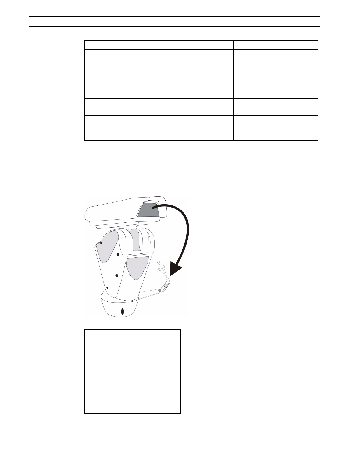
52 en | Configuring the System High-speed Positioning System
Feature Description Default Options
TIME ENABLING When set to YES, the
NO YES, NO
functionality is enabled and the
action will be done after the
dwell of inactivity.
When set to NO, no action takes
place after the dwell of inactivity.
MOTION TYPE Enables the type of movement to
be loaded.
DWELL BEFORE ACT. Interval that the joystick is
HOME HOME, AUTOPAN,
PATROL
00050 00005 to 01000 sec.
inactive before the movement
setting is loaded.
8.3.4 Wiper-Washer
Select UPH Pan/Tilt models have a wiper option used to operate an (external) pump for
cleaning the glass. The spray for cleaning the glass is on the outside of the pan/tilt (see
Figure 8.2). For cleaning, the UPH must be positioned with the glass facing the spray. Start
the pump for the glass cleaning liquid and then start the wiper. It is necessary to set a preset
position corresponding to the spray which is loaded when the “wiper” function is started.
Figure 8.2 Wiper-washer Function
WIPER-WASHER MENU
> 1 - ENABLED : NO
2 - PRESET POSITION : 00001
3 - RELAYS NR. : 00002
4 - PUMP DELAY : 00003
5 - WIPER DURATION : 00005
6 - DELAY WIPER OFF : 00002
F.01U.164.491 | 2.0 | 2010.03 Installation Manual Bosch Security Systems, Inc.
Page 52
High-speed Positioning System Configuring the System | en 53
Feature Description Default Options
ENABLED Enables the wiper function. NO YES, NO
PRESET POSITION Enables the preset position to be
00001 00001 to 00250
reached.
RELAYS NR. Enables the relay to activate for water
00002 00001 to 00002
pump control.
PUMP DELAY The delay between the pump command
00003 00001 to 00050
and when the wiper starts moving.
WIPER DURATION The amount of time that the wiper wipes. 00005 00001 to 00050
DELAY WIPER The amount of time that the wiper wipes
00002 00001 to 00050
without water.
8.3.5 Alarms
The Alarms menu is used to set up the action and duration of the alarm when it is activated.
MOTION PARAMETERS MENU ALARM MENU
1 - SPEED > 1 - ACTION: : SCAN
2 - LIMITS 2 - NR. : 1
3 - PRESET/PATROL/AUTOPAN " 3 4 - WIPER-WASHER 4 - SHOW MESSAGE : NO
" 5 - ALARMS 5 - DURATION : 00000
6 - TXT: Test Alarm 1
ALARMS MENU TEST ALARMS MENU
> 1 - ALARM 1 1 - ALARM 1 : OFF
2 - ALARM 2 2 - ALARM 2 : OFF
3 - ALARM 3 3 - ALARM 3 : OFF
4 - ALARM 4 4 - ALARM 4 : OFF
> 5 - ALARMS TEST
Feature Description Default Options
ACTION Enables the action to take place when
the alarm is activated.
DISABLE DISABLE, SCAN,
RELAY,
AUTOPAN,
PATROL, IR FILT
SHOW MESSAGE Enables the display of an alarm
NO YES, NO
message.
DURATION Length (in seconds) of alarm message
00000 00000 to 01000
display (0 means for the complete
duration of the alarm).
Bosch Security Systems, Inc. Installation Manual F.01U.164.491 | 2.0 | 2010.03
Page 53

54 en | Configuring the System High-speed Positioning System
Feature Description Default Options
TXT: Test Alarm 1 Text associated with the alarm.
ALARMS TEST Displays the status of Alarm Inputs 1, 2,
3, and 4; either ON or OFF status (not
user selectable).
8.4 Camera/Infrared Parameters
This section covers the lens module options, area masking, and the infrared parameters menu.
8.4.1 Lens Modules Parameters and Area Masking
MODULE PARAMETERS
MODULE PARAMETER > 1 - ENABLED ZOOM YES
> 1 - ZOOM/FOCUS/IRIS > * 2 - WINDOW ZOOM 003
2 - AREAS MASKING > 3 - ENABLED FOCUS YES
3 - IR PROBE: INT* * 4 - WINDOW FOCUS 003
5 - ENABLED IRIS YES
* 6 - WINDOW IRIS 003
8 - DEFAULT VALUES
LOADING
MASKING MANAGEMENT MENU AREAS MASKING TEXT MENU EDIT TEXT MENU
> 1 - MASK TEXT > > 1 - MASK. 1 > 1 - STRING EDIT
2 - MASK POSITION > 2 - MASK. 2 -----------------------------
3 - MASK. 3 TEST MASK 1
4 - MASK. 4 ----------------------------5 - MASK. 5 2 - DELETE STRING
6 - MASK. 6
7 - MASK. 7
8 - MASK. 8
TEST MASK 1
AREA MASKING MENU
> 1 - AREA 1 + 0.00 + 0.00
2 - AREA 1 + 0.00 + 0.00
3 - AREA 1 + 0.00 + 0.00
4 - AREA 1 + 0.00 + 0.00
5 - AREA 1 + 0.00 + 0.00
6 - AREA 1 + 0.00 + 0.00
7 - AREA 1 + 0.00 + 0.00
8 - AREA 1 + 0.00 + 0.00
TEST MASK 1
The “windows” are the thresholds used to determine that the saved pre-position has been
reached. The threshold values range from 3 to 10 and refer to the voltage reading on the lens
feedback potentiometers. A lower value indicates less hysteresis tolerance when reading the
stored positions, while a higher value will indicate a wider margin when reading the positions.
F.01U.164.491 | 2.0 | 2010.03 Installation Manual Bosch Security Systems, Inc.
Page 54
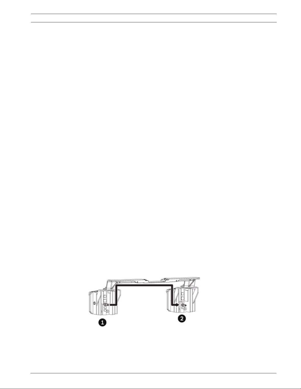
High-speed Positioning System Configuring the System | en 55
The configuration should be based on the parameters of the motorized lens zoom lens being
used.
8.4.2 Infrared Parameters
The IR probe feature is used to control the switching of the IR illuminators and the camera
from the Day to the Night mode. The following modes are available:
1. OFF: None of the operative modes designed to manage the IR illuminators is active.
2. Internal: The photo-sensor internal to the IR illuminators is used to control the Day/Night
operation.
– Power is always provided to the illuminator power inputs by the HSPS internal power
source. The photo-sensor internal to the IR illuminators operates as follows:
Day: Illuminators are OFF and the HSPS Day/Night relay contact to the camera is OPEN.
Night: The photo-cell detects low light conditions, the illuminators turn ON, the HSPS
Day/Night relay CLOSES, and the camera programming forces it into Night Mode.
3. External: An external photo-sensor is connected to the LNO terminal to control the Day/
Night operation.
– Power to the illuminator power inputs is controlled (ON/OFF) by the HSPS internal
power source.
– The external photo-sensor is used to control the ON/OFF state as follows:
Day: The relay output of the sensor is OPEN, the HSPS removes power from the
Illuminators, and the HSPS Day/Night relay contact to the camera is OPEN.
Night: The photo-cell detects low light conditions, relay output of the sensor is CLOSED,
the HSPS applies power to the illuminators, the HSPS Day/Night relay CLOSES, and the
camera programming forces it into Night Mode.
8.4.3 Illuminator/Dinion Configuration
The illuminators and the Dinion camera both require the following configurations to operate in
these 2 different modes. Two additional choices are available for this type of operation:
1. No Synchronization - both illuminators have an internal photo-cell and are set to operate
independently of each other. This is the default configuration.
2. Synchronization (Optional Cable P/N UFLED-CL-1M)
– Use of this cable and the following adjustments will allow the illuminators to be
synchronized so that they will both activate at the same time.
– Connect the cable between the Day/Night output contact of illuminator 1 and the
Telemetry input of illuminator 2 as shown.
3. Set the trip threshold of the two (2) illuminators (see Table 8.6). This is the preferred
configuration when using the INTERNAL sensors.
Figure 8.3 Setting the Trip Threshold
Bosch Security Systems, Inc. Installation Manual F.01U.164.491 | 2.0 | 2010.03
Page 55

56 en | Configuring the System High-speed Positioning System
Reference # Description
1 Illuminator 1 - The unit has been set at the factory, so adjustment
should not be required. If desired, adjust the sensitivity until the
desired night time switching level has been reached.
2 Illuminator 2 - Adjust the sensitivity to the full clock-wise position. The
unit will now be OFF when the telemetry input if OPEN (illuminator 1 if
OFF), and ON when the telemetry input is CLOSED (illuminator 1 ON).
Tab le 8 .6 Setting the Trip Threshold of the two (2) Illuminators
External Operation: No synchronization cable is required, but the SENSITIVITY of the IR
illuminators must be adjusted fully clock-wise.
Dinion: The Dinion camera must be programmed the same no matter which mode of operation
is being used. Program the Dinion to respond to the change in state of the HSPS Day/Night
relay as follows:
1. Press ON-801-ENTER on the keyboard to display the Dinion Install menu.
2. Use the joystick to highlight the I/O menu, and then press FOCUS.
3. Use the joystick to highlight the ALARM menu, and then press FOCUS.
4. Move the joystick left to change ACTIVE to LOW.
5. Highlight ACTION and change this to MONO.
6. Highlight EXIT and then press FOCUS.
7. Highlight EXIT again and press FOCUS.
8. Highlight EXIT again and press FOCUS.
8.5 Load Default Configuration
DEFAULT VALUES MENU
1 - LOAD DEF. VALUES? YES
2 - DELETE ALL PRST? NO
ATTENTION!!!
RELOAD ALL SETTINGS EXCEPT FOR PRESETS
F.01U.164.491 | 2.0 | 2010.03 Installation Manual Bosch Security Systems, Inc.
Page 56

High-speed Positioning System Configuring the System | en 57
The Load Default menu is used to load the default settings.
DEFAULT VALUES MENU
1 - LOAD DEF. VALUES? NO
2 - DELETE ALL PRST? YES
ATTENTION!!!
CLEARS ONLY THE PRESETS
Tab le 8 .7 Clear All Presets
8.6 Setup Info Menu
The Setup Info menu is used to check the device configuration and the software versions of
the UPH boards.
SETUP INFO MENU
NET board : MPP board:
ver. BOSCH xx ver. BOSCH xx
mm/dd/yy mm/dd/yy
HD r.x HD r.x
Protocol : BOSCH
Baudrate : 38400
Address : 00001
Enabled RS485 : TX-RX
FWInt xx FWCam: xx
Bosch Security Systems, Inc. Installation Manual F.01U.164.491 | 2.0 | 2010.03
Page 57

58 en | Keyboard Commands List - Bosch High-speed Positioning System
9 Keyboard Commands List - Bosch
Setup and Configuration
Open OSD configuration: AUX ON - 200 - Enter
XF
Dinion
Dinion
Receiver reset/home: AUX ON - 911 - Enter
Receiver offset re-calibration: AUX ON - 204 - Enter
Auxiliary Connections
Relay number 2 activation: AUX ON - 65 - Enter
Relay number 2 de-activation: AUX OFF - 65 - Enter
Wiper start: AUX ON - 202 - Enter
Wiper stop: AUX OFF - 202 - Enter
Washer start: AUX ON - 201 - Enter
Presets
Store preset position: Set Shot - n - Enter (n = 01 - 99, i.e. 99 presets)
Move to a preset position: Show Shot - n - Enter (n = 01 - 99, i.e. 99 presets)
Erase preset position: Show Shot - 9n - Enter (n = 01 - 99, e.g. to erase preset position #31,
then push Show Shot - 931 - Enter)
Standard preset patrol start: AUX ON - 8 - Enter
Standard preset patrol stop: AUX OFF - 8 - Enter
Recalibrate presets: AUX ON - 204 - Enter
main menu on: AUX ON - 46 - Enter
XF
installation menu on: AUX ON - 801 - Enter
Autopan (requires left and right limits to be set in Motion Parameters menu)
Autopan start: AUX ON
Autopan stop: AUX OFF - 1 - Enter
- 1 - Enter
9.1 Keyboard Commands List - Pelco
Setup and Configuration
Open OSD configuration: 95 - PRESET (press and hold for 2 seconds)
XF
Dinion
DinionXF installation menu on: 83 - PRESET
Receiver reset/home: 94 - PRESET
Receiver offset re-calibration: 84 - PRESET
Auxiliary Connections
Relay number 2 activation: AUX - 3 - ON
Relay number 2 de-activation: AUX - 3 - OFF
Wiper start: AUX - 1 - ON
Wiper stop: AUX - 1 - OFF
Washer start: AUX - 2 - ON
Presets
Store preset position: n - PRESET >2 seconds (n = 01 - 99, i.e. 99 presets)
Move to a preset position: n - PRESET (n = 01 - 99, i.e. 99 presets)
Erase preset position: Not available
Recalibrate presets: 84 - PRESET
main menu on: 85 - PRESET
F.01U.164.491 | 2.0 | 2010.03 Installation Manual Bosch Security Systems, Inc.
Page 58

High-speed Positioning System Keyboard Commands List - Bosch | en 59
Autopan (requires left and right limits to be set in Motion Parameters menu)
Autopan start: 99 - PRESET
Autopan stop: 96 - PRESET
9.2 Changing the Settings
To change a setting, proceed as follows:
1. AUX ON - 200 - Enter to enable the OSD using Bosch protocol (Bilinx or Biphase
connection); Pelco protocol (RS485-2 connection) uses 95 - PRESET.
2. Move the cursor to the parameter to be changed.
3. Press the confirmation (Focus) button. The field starts flashing, indicating that it is in
change mode. Operating the joystick (up and down) shows the alternative choices.
4. After identifying the desired selection, press the confirmation (Focus) button; the
parameter stops flashing.
5. To go back one menu, press (Iris) button; continue to press (Iris) button to exit the OSD.
9.3 Changing the Numeric Fields
To change a numeric field, proceed as follows:
1. Use the joystick to scroll to the parameter you would like to edit.
2. Press the confirmation (Focus) button. The cursor starts flashing for the character to be
changed, indicating it is in edit mode.
– The minimum and maximum values allowed are displayed at the bottom of the
screen. If you try to insert a value outside the limits, the field is forced to the
minimum or maximum allowed value.
– Operating the joystick (up and down) shows the alternative choices. If there is more
than one field on the same line, it is necessary to select the field by moving the
joystick (left and right).
3. After making the change, press the confirmation (Focus) button.
– The first digit in the numeric field to be changed flashes and the last line of the
display shows the accepted limits for the field.
– Move within the field (left and right) and change the sign or the numeric value
(up and down).
4. To go back one menu, press (Iris) button; continue to press (Iris) button to exit the OSD.
Bosch Security Systems, Inc. Installation Manual F.01U.164.491 | 2.0 | 2010.03
Page 59
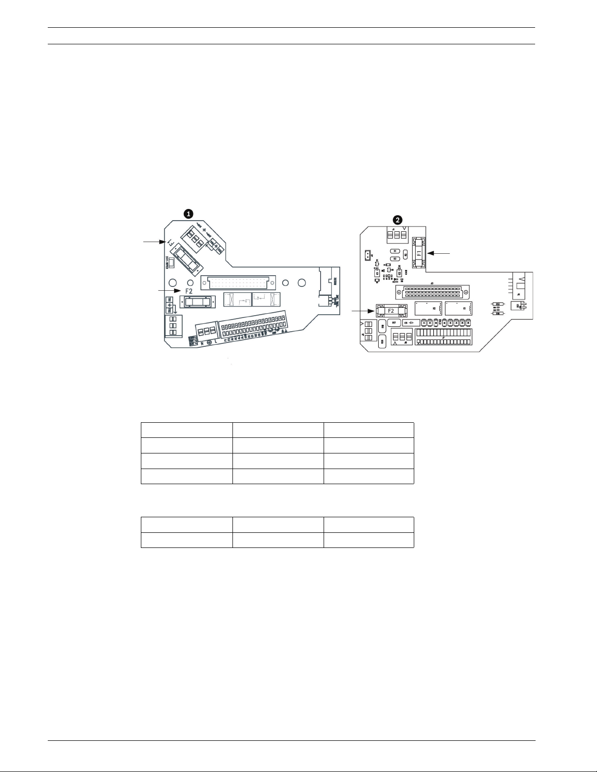
60 en | Maintenance High-speed Positioning System
10 Maintenance
UPH pan/tilt devices require no particular maintenance.
10.1 Cleaning
To clean the device, use neutral detergent and a non-abrasive cloth.
10.2 Replacing the Fuses
There are two (2) preset fuses on the connection board. Sizes are related to the power supply
voltage, as shown in the table below.
Figure 10.1 Fuses on the Connection Board
Standard Models: Fuse Values for Replacement (Reference #1)
Refer to Figure 10.1, Item 1, above for fuse locations.
Voltage Fuse F1 Fuse F2
24 VAC 50/60 Hz T 4A L 250 V T 6.3A H 250 V
120 VAC 50/60 Hz T 4A L 250 V T 4A H 250 V
230 VAC 50/60 Hz T 4A L 250 V T 2A H 250 V
IR Modes: Fuse Values for Replacement (Reference #2)
Refer to Figure 10.1, Item 2, above for fuse locations.
Voltage Fuse F1 Fuse F2
24 VAC 50/60 Hz T 4A L 250 V T 8A H 250 V
F.01U.164.491 | 2.0 | 2010.03 Installation Manual Bosch Security Systems, Inc.
Page 60

High-speed Positioning System Troubleshooti ng | e n 61
11 Troubleshooting
Problem Possible Cause Solution
The device is switched off
and shows no signs of life.
There is no image on the
screen, just a blue screen
with the message NO
VIDEO SIGNAL!!!
Presets are not as accurate
as they were during
installation.
Under particular zoom
conditions, the housing or
sunshield interferes with
the image (only for versions
with motorized lens).
De-icing counter appears on
the screen and user has no
control.
Data transfer stops. Power spike/
The monitor always displays
the firmware version with
the message, Dip-switch
upgrade ON.
There is no video. Wire(s) may be
Incorrect wiring, fuses
blown.
Incorrect camera or
module wiring, camera
failure.
Wind, vibration, and
other environmental
conditions.
The camera is too far
behind the glass.
It is too cold for the
UPH to safely be used.
fluctuation or spurious
noise on video/data
line.
Programming dip
switch on (up
position).
installed incorrectly.
Make sure all the connections are
correct, check the continuity of the
fuses and, if there is a failure, replace
them according to the values shown in
the table.
Note: if the fuses blow repeatedly,
contact the authorized service centre.
Make sure all connections are correct
for the camera version and motorized
lenses.
AUX On - 204 - Enter command
recalibrates presets; takes 30-45
seconds to complete.
Adjust the camera position by
adjusting the slide until the correct
position is found.
Wait for de-icing procedure to
complete (30-105 minutes).
Reset power on UPH and the unit
recovers, although some OSD changes
may be lost and need to be re-entered.
Switch off the pan and tilt, switch off
(down position) the “PROGRAM.” dip
switch (dip-switch number 1 in the
Factory Use section) and then switch
the device on again.
Re-check all wires and cables to
ensure that they are properly secure.
Monitor input may be
on incorrect setting.
The motor may be
working improperly.
Note! Over time, due to environmental factors such as wind and vibration, preset positions
may not always align with what they were at installation. Use AUX ON - 204 - Enter to correct
this. It takes 30-45 seconds to cycle through this process, during which time there is no user
control. Once it has finished the process and corrected for the effect of any environmental
factors, the user regains full control.
Bosch Security Systems, Inc. Installation Manual F.01U.164.491 | 2.0 | 2010.03
Verify that monitor is displaying the
correct input setting.
Remove power to the unit, re-apply
power, and allow the device to go
through its homing phase.
Page 61
62 en | Troubleshooting High-speed Positioning System
11.1 Low and High Temperatures
Systems in the UPH line are switched on by simply connecting the power supply, and
switched off by disconnecting the power supply. When the UPH is powered up in an
environment below 0 °C, the device checks it’s internal components to make sure that they
are warm enough to start without damage. If the internal components’ temperatures are too
low, the OSD displays a warning message and the UPH automatically enters its de-icing mode.
In de-icing mode the UPH is powered in an attempt to raise its internal temperature. A timer
appears on the screen and counts down showing how much time remains for de-icing to
complete.
NOTICE!
De-icing can take between 30 and 105 minutes, after which time it is ready for use, assuming
that a safe internal temperature is reached; otherwise, it is too cold to safely operate the UPH
and it remains off.
NOTICE!
High temperatures can also have a negative effect on camera image. If the ambient (outside)
air temperature exceeds 40 leg Celsius (104° F), the HSPT will continue to operate; however,
some unusual effects may appear on the video signal. These are blemishes that appear as very
small white dots on the video picture. They are usually only noticeable during, and a few hours
after, dusk, when the overall scene becomes darker, and the housing is still cooling down as
the sun goes down.
Continued exposure of the HSPT to excessive ambient (outside) air temperatures will effect
the long-term reliability of the HSPT, cause blemishes to become more severe, and may
introduce fixed pattern noise (FPN) on the video signal.
Solution: via Bilinx change the SensUp setting in the camera to OFF; this reduces the number
and intensity of the blemishes.
F.01U.164.491 | 2.0 | 2010.03 Installation Manual Bosch Security Systems, Inc.
Page 62
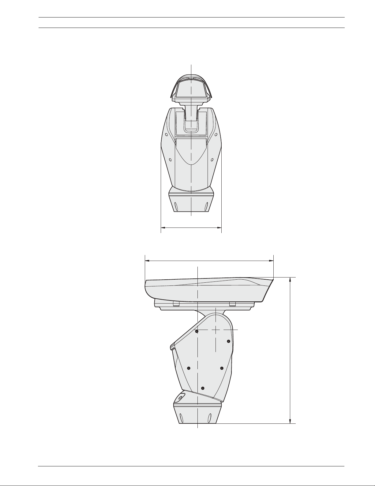
High-speed Positioning System Troubleshooti ng | e n 63
258 (10.16)
11.2 Dimensions and Range of Movement
514 (20.24)
584 (22.99)
Bosch Security Systems, Inc. Installation Manual F.01U.164.491 | 2.0 | 2010.03
Page 63
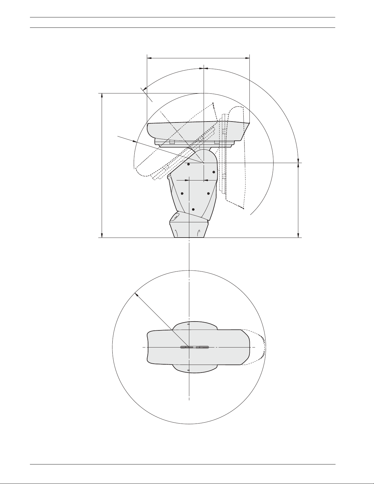
64 en | Troubleshooting High-speed Positioning System
514 (20.24)
-40º
90º
R350
(13.78)
724 (28.50)
73
(2.87)
374 (14.72)
R385 (15.16)
Figure 11.1 Dimensions and Range of Movement
F.01U.164.491 | 2.0 | 2010.03 Installation Manual Bosch Security Systems, Inc.
Page 64

High-speed Positioning System | en 65
A Wiring Summary
Standard
Reference Description
F1 Feed 1, 24 VAC for optional washer
F2 Feed 2, 24 VAC for optional washer
AL1 Alarm 1 Input; triggered by external DC voltage
AL2 Alarm 2 Input; triggered by external DC voltage
AL3 Alarm 3 Input; triggered by external DC voltage
AL4 Alarm 4 Input; triggered by external DC voltage
Com Alarm Common (ground)
O1 Output 1; Normally Open; Dry contact relay output
C1 Common 1; common for Output 1
O2 Output 2; Normally Open; Dry contact relay output
C2 Common 2; common for Output 2
GND Video ground, braid of coax
VIDEO “Video output, center conductor of coax (BILINX protocol)”
RS-485-1 Not used
ANot used
BNot used
RS-485-2 Pelco D protocol, 2400 baud, 8, N, 1
A Data (connect to Pelco controller output TX -)
B Data (connect to Pelco controller output TX+)
B+ Biphase + (OSRD protocol)
B- Biphase - (OSRD protocol)
IR
Reference Description
F1 Feed 1, 24 VAC for optional washer
F2 Feed 2, 24 VAC for optional washer
AL1 Alarm 1 Input; triggered by external DC voltage
AL2 Alarm 2 Input; triggered by external DC voltage
LNO External IR Probe, Normally Open Contact
AGND Alarm Ground & External IR probe common
O1 Output 1; Normally Open; Dry contact relay output
C1 Common 1; common for Output 1
GND Video ground, braid of coax
VIDEO “Video output, center conductor of coax (BILINX protocol)”
RS-485-1 Not used
ANot used
BNot used
RS-485-2 Pelco D protocol, 2400 baud, 8, N, 1
A Data (connect to Pelco controller output TX -)
B Data (connect to Pelco controller output TX+)
Bosch Security Systems, Inc. Installation Manual F.01U.164.491 | 2.0 | 2010.03
Page 65

66 en | High-speed Positioning System
IR
Reference Description
B+ Biphase + (OSRD protocol)
B- Biphase - (OSRD protocol)
F.01U.164.491 | 2.0 | 2010.03 Installation Manual Bosch Security Systems, Inc.
Page 66
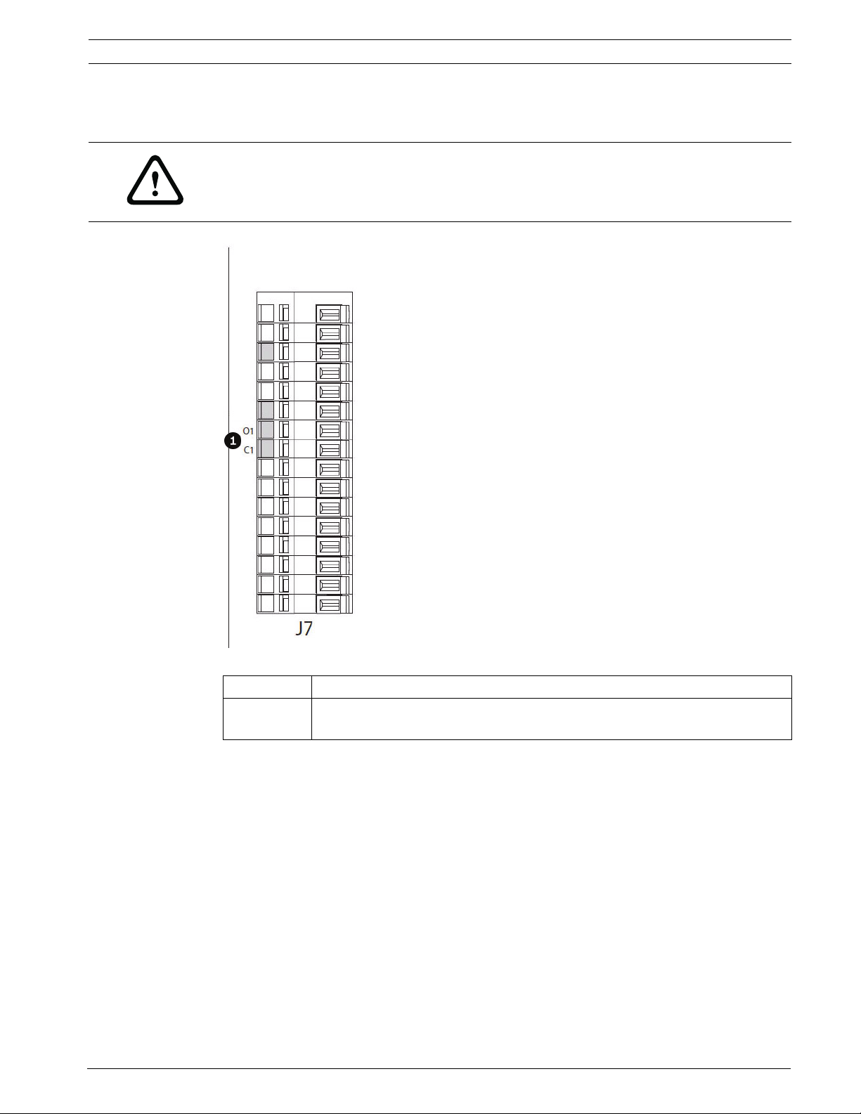
High-speed Positioning System | en 67
B Connecting the Pump
WARNING!
The connections illustrated below should be made only and exclusively by skilled operatives
who should comply scrupulously with all the wiring and power supply instructions. Failure to
do so could create serious risks for the operator and would invalidate the guarantee.
Figure 2.1 J7 connector on the base board of the pan and tilt. All models have this function.
Reference # Description
1 Activation pump contact. O1 - C1: Clean contact output for starting the water
pump (max. 50 VDC/30 VAC, 1 A).
B.1 Connecting a Washer System in the HAC-WAS05-20
For the connections, see the product installation handbook.
Bosch Security Systems, Inc. Installation Manual F.01U.164.491 | 2.0 | 2010.03
Page 67

68 en | High-speed Positioning System
F.01U.164.491 | 2.0 | 2010.03 Installation Manual Bosch Security Systems, Inc.
Page 68

Page 69

Bosch Security Systems, Inc.
www.boschsecurity.com
© Bosch Security Systems, Inc., 2010; Data subject to change.
 Loading...