

Page 1
Universal Monitor Mounts
UMM-LW-20B | UMM-LW-30B
en Mounting Guide
Page 2

ii en | Table of Contents Universal Monitor Mounts
Table o f C o n tents
1Unpacking 1
2 Universal Monitor Mount Models 1
2.1 UMM-LW-20B Fixed Wall Mount 2
2.1.1 Parts List 4
2.1.2 Installing the UMM-LW-20B Fixed Wall Mount 5
2.2 UMM-LW-30B Tilt/Swivel Wall Mount 9
2.2.1 Parts List 11
2.2.2 Installing the UMM-LW-30B Tilt/Swivel Wall Mount 12
3 Dimensional Drawings 16
3.1 UMM-LW-20B Fixed Wall Mount 16
3.2 UMM-LW-30B Tilt/Swivel Wall Mount 17
3.3 UMM Series Component Dimensions 18
F.01U.115.026 | 3.0 | 2008.12 Mounting Guide Bosch Security Systems, Inc.
Page 3

Universal Monitor Mounts Unpacking | en 1
1 Unpacking
This equipment should be unpacked and handled with care. If an item appears to
have been damaged in shipment, notify the shipper. Verify that all parts shown in
the Parts List are included. If any items are missing, notify your Bosch Security
Systems Sales or Customer Service Representative.
The original packing carton is the safest container in which to transport the unit.
Save it for possible future use.
2 Universal Monitor Mount Models
The Bosch series of Universal Monitor Mounts (UMM) are designed to mount any
VESA®-compliant monitor to a wall. The two types of mounts offered in the series
of Universal Monitor Mounts (UMM) are the UMM-LW-20B and the UMM-LW-30B.
Bosch Security Systems, Inc. Mounting Guide F.01U.115.026 | 3.0 | 2008.12
Page 4
2 en | Universal Monitor Mount Models Universal Monitor Mounts
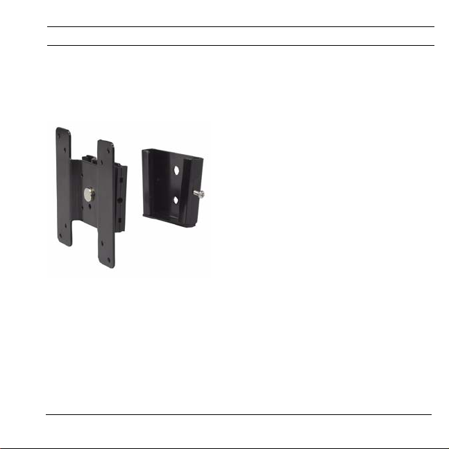
2.1 UMM-LW-20B Fixed Wall Mount
The UMM-LW-20B is a fixed wall mount that is designed for use with any Bosch
LCD flat-screen monitor. The mount moves the monitor 1.5 cm (0.59 in.) off of the
wall.
Figure 2.1 UMM-LW-20B Fixed Wall Mount
F.01U.115.026 | 3.0 | 2008.12 Mounting Guide Bosch Security Systems, Inc.
Page 5
Universal Monitor Mounts Universal Monitor Mount Models | en 3
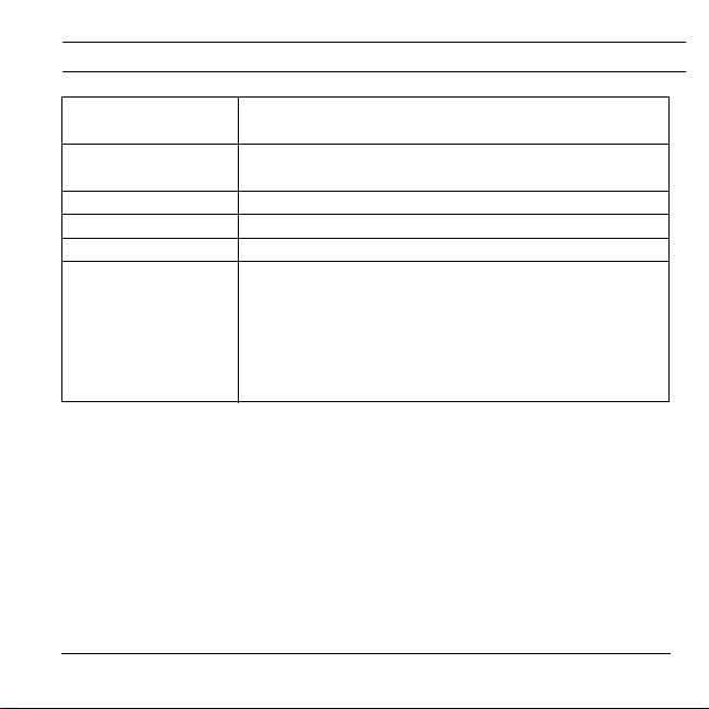
Maximum Weight
Capacity
:
Monitor Mounting
12 kg (26.5 lbs)
VESA 75 (75 mm) and VESA 100 (100 mm)
Holes:
Material: Steel
Color: Black
Swivel Adjustment: 360°
Recommended
Mounting Surface:
Solid concrete with a recommended strength of
3600 psi or 25 Mpa
.
Hollow cinder block.
Minimum 2-in. x 4-in. wood stud with maximum 0.5-
in. thick wallboard
.
3/4-in. construction grade plywood.
Tab le 2. 1 UMM-LW-20B Specifications
Bosch Security Systems, Inc. Mounting Guide F.01U.115.026 | 3.0 | 2008.12
Page 6
4 en | Universal Monitor Mount Models Universal Monitor Mounts
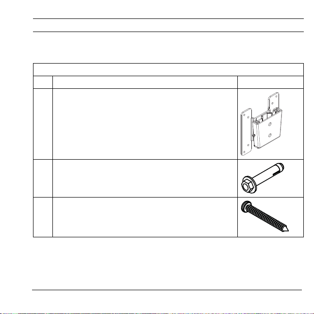
2.1.1 Parts List
The following table lists the components for the mount:
UMM-LW-20B
Qty Description Illustration
1 VESA mounting plate (A) and wall bracket (B)
(see Figure 3.1 on page 16 for a dimensional drawing)
2 1/4 x 2.0 in. Wedge anchors (C)
(see Figure 3.3 on page 18 for a dimensional drawing)
2 1/2 x 2.0 in. Wood screws (D)
(see Figure 3.3 on page 18 for a dimensional drawing)
F.01U.115.026 | 3.0 | 2008.12 Mounting Guide Bosch Security Systems, Inc.
Page 7
Universal Monitor Mounts Universal Monitor Mount Models | en 5
UMM-LW-20B
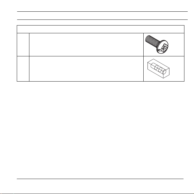
4 M4 x 10 mm screws (E)
(see Figure 3.4 on page 19 for a dimensional drawing)
1 Level (F)
2.1.2 Installing the UMM-LW-20B Fixed Wall Mount
To install the wall mount:
1. Disassemble the mounting plate (A) from the wall bracket by removing the
lock screw from the wall bracket (B). Retain the lock screw for later use.
2. Determine the location on the wall that you will attach the wall bracket. Use
Table 2.1, on page 3, for recommended mounting surfaces.
Bosch Security Systems, Inc. Mounting Guide F.01U.115.026 | 3.0 | 2008.12
Page 8
6 en | Universal Monitor Mount Models Universal Monitor Mounts
3. Place the wall bracket (B) against the wall, as illustrated below, and use the
level (F) to ensure that the bracket is level.
Figure 2.2 Wall bracket with level
4. Use the wall bracket as a template to mark the mounting holes on the wall.
5. Attach the wall bracket (B) to the wall.
a. Use the two (2) wedge anchors (C) to attach the wall bracket to
concrete or to a cinder block.
b. Use the two (2) wood screws (D) to attach the wall bracket to a stud
behind wallboard or to construction-grade plywood.
F.01U.115.026 | 3.0 | 2008.12 Mounting Guide Bosch Security Systems, Inc.
Page 9

Universal Monitor Mounts Universal Monitor Mount Models | en 7
75
100
6. Attach the VESA mounting plate (A) to the back of the flat-panel LCD manual
using the four (4) M4 x 10 mm screws (E).
75
100
Figure 2.3 Attach the VESA monitor plate
7. Carefully slide the mounting plate into the slots of the wall bracket.
Figure 2.4 Attach monitor plate to wall bracket
Bosch Security Systems, Inc. Mounting Guide F.01U.115.026 | 3.0 | 2008.12
Page 10

8 en | Universal Monitor Mount Models Universal Monitor Mounts
8. Tighten the lock screw, located on the right side of the wall bracket, using a
Phillips head screw driver.
Figure 2.5 Lock screw on the wall bracket
F.01U.115.026 | 3.0 | 2008.12 Mounting Guide Bosch Security Systems, Inc.
Page 11

Universal Monitor Mounts Universal Monitor Mount Models | en 9
2.2 UMM-LW-30B Tilt/Swivel Wall Mount
The UMM-LW-30B is a tilt/swivel wall mount that is designed for use with any
Bosch LCD flat-screen monitor. This mount allows you to swivel the mount 360
degrees to position the monitor in either landscape or portrait view. The mount
also allows you to pan and tilt the monitor 140 (±70) degrees for the best viewing
angle.
Figure 2.6 UMM-LW-30B Tilt/Swivel Wall Mount
Bosch Security Systems, Inc. Mounting Guide F.01U.115.026 | 3.0 | 2008.12
Page 12

10 en | Universal Monitor Mount Models Universal Monitor Mounts
!
Maximum Weight
Capacity
Monitor Mounting
Holes:
Material
Color: Black
Swivel Adjustment:
Pan Range: 140° (±70°)
Tilt Range 140° (±70°)
Recommended
Mounting Surface:
Tab le 2. 2 UMM-LW-30B Specifications
F.01U.115.026 | 3.0 | 2008.12 Mounting Guide Bosch Security Systems, Inc.
:
: Steel
12 kg (26.5 lbs)
VESA 75 (75 mm) and VESA 100 (100 mm)
360°
Minimum 2-in. x 4-in. wood stud with maximum 0.5-in.
thick wallboard
Minimum 2-in. x 4-in. wood stud with maximum 0.5-in.
thick plywood
Solid concrete with a recommended strength of 3600
psi or 25 Mpa
WARNING! Do not install the UMM-LW-30B wall bracket into mortar
joints or non-filled cinder block walls.
.
.
.
Page 13

Universal Monitor Mounts Universal Monitor Mount Models | en 11
2.2.1 Parts List
The following table lists the components for the mount:
UMM-LW-30B
Qty Description Illustration
1 VESA mounting plate (A) and wall bracket (B)
(see Figure 3.2 on page 17 for a dimensional
drawing)
2 1/4 x 2.0 in. Wedge anchors (C)
(see Figure 3.3 on page 18 for a dimensional
drawing)
2 1/2 x 2.0 in. Wood screws (D)
(see Figure 3.3 on page 18 for a dimensional
drawing)
Bosch Security Systems, Inc. Mounting Guide F.01U.115.026 | 3.0 | 2008.12
Page 14

12 en | Universal Monitor Mount Models Universal Monitor Mounts
UMM-LW-30B
4 M4 x 10 mm screws (E)
(see Figure 3.4 on page 19 for a dimensional
drawing)
1 Level (F)
1 Wrench (G)
2.2.2 Installing the UMM-LW-30B Tilt/Swivel Wall Mount
To install the wall mount:
1. Disassemble the VESA mounting plate (A) from the wall bracket (B) by
removing the thumb screw on the wall bracket. Retain the thumb screw for
later use.
2. Determine the location on the wall that you will attach the wall bracket (B).
Use Table 2.2, on page 10, for recommended mounting surfaces.
F.01U.115.026 | 3.0 | 2008.12 Mounting Guide Bosch Security Systems, Inc.
Page 15

Universal Monitor Mounts Universal Monitor Mount Models | en 13
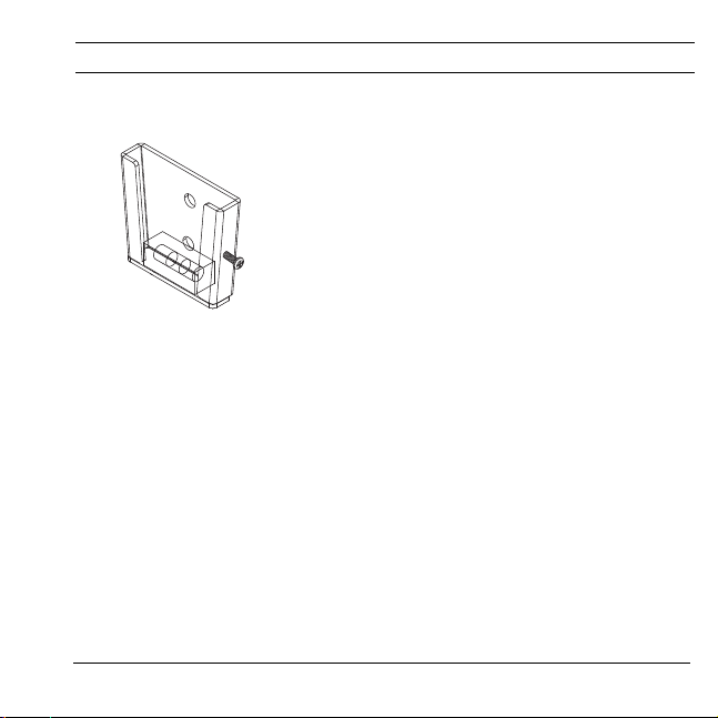
3. Place the wall bracket (B) against the wall, as illustrated below, and use the
level (F) to ensure that the bracket is level.
Figure 2.7 Wall bracket with level
4. Use the wall bracket as a template to mark the mounting holes on the wall.
5. Attach the wall bracket (B) to the wall.
a. Use the two (2) wedge anchors (C) to attach the wall bracket to
concrete.
b. Use the two (2) wood screws (D) to attach the wall bracket to a stud
behind wallboard or behind construction-grade plywood.
6. Align the back of the monitor to the correct hole pattern on the VESA
mounting plate.
Bosch Security Systems, Inc. Mounting Guide F.01U.115.026 | 3.0 | 2008.12
Page 16

14 en | Universal Monitor Mount Models Universal Monitor Mounts
7. Attach the VESA mounting plate (A) to the back of the flat-panel LCD manual
using the four (4) M4 x 10 mm screws (E).
Figure 2.8 Attach the VESA mounting plate
8. Carefully slide the mounting plate into the slots of the wall bracket.
Figure 2.9 Attach mon itor plate to wall bracket
F.01U.115.026 | 3.0 | 2008.12 Mounting Guide Bosch Security Systems, Inc.
Page 17

Universal Monitor Mounts Universal Monitor Mount Models | en 15
9. Tighten the thumb screw, located on the right side of the wall bracket.
Figure 2.10 Thumb screw on the wall bracket
10. Tilt and swivel the mount to achieve the optimum viewing angle.
11. Use the wrench (G) to tighten the nut, located on the left side of the mount.
Figure 2.11 Tighten nut to lock mount position
Bosch Security Systems, Inc. Mounting Guide F.01U.115.026 | 3.0 | 2008.12
Page 18

16 en | Dimensional Drawings Universal Monitor Mounts
3 Dimensional Drawings
3.1 UMM-LW-20B Fixed Wall Mount
75
30
65
30
10 0 m m
8.5
Figure 3.1 UMM-LW-20B Dimensional Drawing
F.01U.115.026 | 3.0 | 2008.12 Mounting Guide Bosch Security Systems, Inc.
79
Page 19

Universal Monitor Mounts Dimensional Drawings | en 17
8.5
75
129
30
65
79
100 mm
140
140
3.2 UMM-LW-30B Tilt/Swivel Wall Mount
Figure 3.2 UMM-LW-30B Dimensional Drawing
Bosch Security Systems, Inc. Mounting Guide F.01U.115.026 | 3.0 | 2008.12
Page 20

ø6 mm
ø5 mm
1/4 in. x 20
41 mm
45.5 mm
9.8 mm
11.32 mm
ø12.5 mm
ø6.3 mm
56 mm
52 mm
18 en | Dimensional Drawings Universal Monitor Mounts
3.3 UMM Series Component Dimensions
Figure 3.3 Wedge Anchor and Wood Screw Dimensions
F.01U.115.026 | 3.0 | 2008.12 Mounting Guide Bosch Security Systems, Inc.
Page 21

Universal Monitor Mounts Dimensional Drawings | en 19
ø7.5±0.15 mm
12.5±0.2 mm
8±0.5 mm
10±0.2 mm
ø3.8±0.05 mm
4 mm x 0.7
ø3.95±0.05 mm
Figure 3.4 M4x10 mm Screw Dimensions
Bosch Security Systems, Inc. Mounting Guide F.01U.115.026 | 3.0 | 2008.12
Page 22

20 en | Dimensional Drawings Universal Monitor Mounts
F.01U.115.026 | 3.0 | 2008.12 Mounting Guide Bosch Security Systems, Inc.
Page 23

Page 24

Bosch Security Systems, Inc.
850 Greenfield Road
Lancaster, PA 17601
USA
Telephone +1 888 289-0096
Fax +1 717 735 6560
www.boschsecuritysystems.us
© Bosch Security Systems, Inc. 2008; F.01U.115.026 | 3.0 | 2008.12
 Loading...