

Page 1
UHI/UHO Series
UHI/UHO Series
de Benutzerhandbuch
en Installation Manual
es Manual del usuario
fr Manuel d’utilisation
it Manuale utente
ja ユーザーマニュアル
nl Gebruikershandleiding
pl Instrukcja instalacji
pt Manual do utilizador
Page 2

Page 3

| 3
de Benutzerhandbuch 4
en Installation Manual 41
es Manual del usuario 76
fr Manuel d’utilisation 114
it Manuale utente 152
ja ユーザーマニュアル 189
nl Gebruikershandleiding 215
pl Instrukcja instalacji 252
pt Manual do utilizador 290
| |
Page 4

4 de | Inhaltsverzeichnis UHI/UHO Serien
Inhaltsverzeichnis
1Sicherheit 6
1.1 Wichtige Sicherheitshinweise 6
1.2 Sicherheitsvorkehrungen 9
1.3 Wichtige Hinweise 10
1.4 Kundendienst und Wartung 16
2 Auspacken 17
3Service 18
4Beschreibung 18
5 Installation 20
5.1 Erforderliche Werkzeuge 20
5.2 Kameraanforderungen 20
5.3 Kabelanforderungen 21
5.3.1 Videoübertragung (Koax) 21
5.3.2 Netzkabel 21
5.3.3 Kabel für Objektivsteuerung 22
5.4 Gehäusemontage 22
5.5 Öffnen der Abdeckung 23
5.6 Installieren von Kamera/Objektiv 24
5.7 Anschließen von Kamera/Objektiv 26
5.7.1 Halterungen 26
5.7.2 Kabelkanal 26
5.7.3 Kabeldurchführung 27
5.7.4 Netzstromanschlüsse 28
5.8 Videokoaxverbindung 32
5.9 Anschließen des Objektivs 33
5.10 Justieren von Kamera/Objektiv 34
5.11 Endmontage 35
5.12 Sonnenblende 35
5.13 Austauschen der Sicherung 36
F.01U.167.418 | v3.0 | 2010.04 Benutzerhandbuch Bosch Secuurity Systems, Inc.
Page 5

UHI/UHO Serien Inhaltsverzeichnis | de 5
6 UHO-HBPS-10, -50 und UHO-HPS-50 36
6.1 Anschließen von Kamera/Objektiv 36
6.2 Videokoaxverbindung 38
7 Betrieb 38
8 Wartung 38
9 Explosionsdarstellung 39
Bosch Secuurity Systems, Inc. Benutzerhandbuc F.01U.167.418 | v3.0 | 2010.04
Page 6

6 de | Sicherheit UHI/UHO Serien
1 Sicherheit
1.1 Wichtige Sicherheitshinweise
Lesen und befolgen Sie alle folgenden Sicherheitshinweise, und
bewahren Sie sie zum Nachschlagen auf. Beachten Sie vor
Inbetriebnahme des Geräts alle Warnungen am Gerät und in der
Betriebsanleitung.
1. Reinigen: Ziehen Sie den Netzstecker des Geräts aus der
Steckdose, bevor Sie es reinigen. Befolgen Sie sämtliche
Anweisungen zum Gerät. Im Allgemeinen reicht es, wenn
Sie zur Reinigung ein trockenes Tuch verwenden. Es kann
jedoch auch ein feuchtes, flusenfreies Tuch oder
Fensterleder verwendet werden. Verwenden Sie keine
flüssigen Reiniger oder Reiniger in Sprühdosen.
2. Wärmequellen: Montieren Sie das Gerät nicht in
unmittelbarer Nähe von Wärmequellen wie Heizkörpern,
Heizgeräten, Öfen oder anderen Geräten (einschließlich
Verstärkern), die Wärme erzeugen.
3. Belüftung: Sofern vorhanden, dienen Öffnungen im
Gehäuse der Belüftung, um eine Überhitzung zu verhindern
und einen verlässlichen Betrieb des Geräts sicherzustellen.
Diese Öffnungen dürfen nicht blockiert oder verdeckt
werden. Bauen Sie das Gerät nur dann in ein Gehäuse ein,
wenn für angemessene Belüftung gesorgt ist oder die
Anweisungen des Herstellers befolgt wurden.
4. Wasser: Verwenden Sie dieses Gerät nicht in der Nähe von
Wasser (Badewanne, Waschbecken, Spüle,
Waschmaschine, feuchter Keller, Schwimmbecken usw.),
in einer Außeninstallation oder an anderen feuchten Orten.
Setzen Sie das Gerät nicht Regen oder Nässe aus, um die
Gefahr eines Brandes oder Stromschlags zu verringern.
5. Eintritt von Fremdkörpern und Flüssigkeit: Stecken Sie
niemals Fremdkörper in die Öffnungen des Geräts, da Sie
so Teile mit hoher Spannung berühren oder Teile
kurzschließen können, was zu Feuer oder einem
elektrischen Schlag führen kann. Verschütten Sie keinerlei
F.01U.167.418 | 3.0 | 2010.04 Benutzerhandbuch Bosch Secuurity Systems, Inc.
Page 7

UHI/UHO Serien Sicherheit | de 7
Flüssigkeit über dem Gerät. Stellen Sie keine mit
Flüssigkeit gefüllten Behälter wie beispielsweise Vasen
oder Tassen auf dem Gerät ab.
6. Blitzeinschlag: Schützen Sie das Gerät zusätzlich während
eines Gewitters oder bei Nichtverwendung über einen
längeren Zeitraum, indem Sie den Stecker aus der
Steckdose ziehen und die Verbindung zum Kabelsystem
trennen. So kann das Gerät nicht durch Blitzeinschlag oder
Überspannung beschädigt werden.
7. Einstellung der Bedienelemente: Stellen Sie nur die in der
Betriebsanleitung angegebenen Bedienelemente ein.
Durch falsche Einstellung anderer Bedienelemente kann
das Gerät beschädigt werden. Durch Verwendung von
Bedienelementen oder Einstellungen sowie Durchführung
von Verfahren, die nicht in der Betriebsanleitung
angegeben sind, kann es zum Austritt gefährlicher
Strahlung kommen.
8. Überlastung: Überlasten Sie Steckdosen und
Verlängerungskabel nicht. Dies kann zu Feuer oder einem
elektrischen Schlag führen.
9. Unterbrechung der Stromversorgung: An Geräten mit
oder ohne Netzschalter liegt Spannung an, sobald der
Netzstecker in die Steckdose gesteckt wird. Das Gerät ist
jedoch nur betriebsbereit, wenn der Netzschalter (ON/
OFF) auf ON steht. Wenn der Netzstecker aus der
Steckdose gezogen wird, ist die Stromversorgung für alle
Geräte unterbrochen.
10. Stromquelle: Das Gerät darf nur mit der auf dem Etikett
genannten Stromquelle betrieben werden. Bevor Sie
Bosch Secuurity Systems, Inc. Benutzerhandbuch F.01U.167.418 | 3.0 | 2010.04
Page 8

8 de | Sicherheit UHI/UHO Serien
fortfahren, sollten Sie überprüfen, dass an dem an das
Gerät anzuschließende Kabel kein Strom anliegt.
– Schlagen Sie bei batteriebetriebenen Geräten in der
Betriebsanleitung nach.
– Verwenden Sie für Einheiten mit externer
Stromversorgung nur empfohlene und geprüfte
Netzteile.
– Für Geräte, die mit einem Netzteil mit eingeschränkter
Leistung betrieben werden, muss das Netzteil der
Norm EN 60950 entsprechen. Andere Ersatznetzteile
können das vorliegende Gerät beschädigen und zu
Feuer oder einem elektrischen Schlag führen.
– Bei Geräten mit 24 VAC darf die Eingangsspannung
am Gerät ±10 % oder 21,6-26,4 VAC nicht
überschreiten. Die vom Kunden bereitgestellte
Verkabelung muss den jeweils geltenden Vorschriften
für elektrische Anlagen (Leistungsstufe 2)
entsprechen. Die Stromquelle darf nicht an den
Anschlüssen bzw. an den
Stromversorgungsanschlüssen am Gerät geerdet
werden.
– Wenn Sie sich nicht sicher sind, ob Sie das Gerät mit
einer bestimmten Stromquelle betreiben können,
fragen Sie den Händler, bei dem Sie das Gerät
erworben haben, oder Ihren Stromanbieter.
11. Wartung: Versuchen Sie nicht, das Gerät selbst zu warten.
Durch Öffnen oder Entfernen von Abdeckungen können Sie
hohen elektrischen Spannungen oder anderen Gefahren
ausgesetzt sein. Wartungsarbeiten sind ausschließlich von
qualifiziertem Wartungspersonal durchzuführen.
12. Beschädigungen, bei denen eine Wartung erforderlich
ist: Ziehen Sie den Netzstecker aus der Steckdose, und
überlassen Sie das Gerät qualifiziertem Personal zur
Wartung, wenn Beschädigungen aufgetreten sind, z. B.:
– Das Netzkabel oder der Netzstecker ist beschädigt.
– Das Gerät ist mit Wasser in Kontakt gekommen und/
oder wurde Feuchtigkeit oder rauen
F.01U.167.418 | 3.0 | 2010.04 Benutzerhandbuch Bosch Secuurity Systems, Inc.
Page 9

UHI/UHO Serien Sicherheit | de 9
Umgebungsbedingungen (z. B. Regen, Schnee usw.)
ausgesetzt.
– Flüssigkeit ist auf oder in das Gerät gelangt.
– Fremdkörper sind in das Gerät gelangt.
– Das Gerät ist zu Boden gefallen, oder das Gehäuse
wurde beschädigt.
– Eine auffällige Veränderung in der Leistung des Geräts
ist aufgetreten.
– Das Gerät funktioniert nicht ordnungsgemäß, obwohl
sich der Benutzer genau an die Betriebsanleitung hält.
13. Ersatzteile: Stellen Sie sicher, dass der Servicemitarbeiter
Ersatzteile verwendet, die vom Hersteller empfohlen
werden bzw. den ursprünglichen Teilen entsprechen. Die
Verwendung falscher Ersatzteile kann zu einem Brand,
einem elektrischen Schlag oder anderen Gefahren führen.
14. Sicherheitstest: Sicherheitstests müssen nach der
Wartung oder Instandsetzung des Geräts durchgeführt
werden, um den ordnungsgemäßen Betrieb zu
gewährleisten.
15. Installation: Bei der Installation sind die Anweisungen des
Herstellers und die jeweils zutreffenden Vorschriften für
elektrische Anlagen zu beachten.
16. Zubehör und Veränderungen: Verwenden Sie nur vom
Hersteller empfohlenes Zubehör. Jede Veränderung des
Geräts, die nicht ausdrücklich von Bosch genehmigt
wurde, führt zum Erlöschen der Gewährleistung oder, im
Fall einer Autorisierungsvereinbarung, zum Erlöschen der
Autorisierung zur Verwendung des Geräts.
1.2 Sicherheitsvorkehrungen
GEFAHR!
Dieses Symbol zeigt eine unmittelbare Gefahrensituation an,
etwa eine gefährliche Spannung im Innern des Produkts. Falls
die Gefahr nicht vermieden wird, führt dies zu elektrischem
Schlag, schweren Verletzungen oder zum Tod.
Bosch Secuurity Systems, Inc. Benutzerhandbuch F.01U.167.418 | 3.0 | 2010.04
Page 10
10 de | Sicherheit UHI/UHO Serien
WARNUNG!
Zeigt eine potenzielle Gefahrensituation an. Falls die Gefahr
nicht vermieden wird, kann dies geringe bis mittelschwere
Verletzungen verursachen. Macht den Benutzer auf wichtige
Anweisungen in den begleitenden Unterlagen aufmerksam.
VORSICHT!
Zeigt eine potenzielle Gefahrensituation an. Falls die Gefahr
nicht vermieden wird, kann dies zu Sachschäden oder zu einer
Beschädigung des Geräts führen.
HINWEIS! Dieses Symbol weist auf Informationen oder auf
Unternehmensrichtlinien hin, die sich direkt oder indirekt auf
die Mitarbeitersicherheit und den Sachschutz beziehen.
1.3 Wichtige Hinweise
Zubehör: Bringen Sie dieses Gerät nicht auf einer instabilen
Halterung, einem Stativ oder Ähnlichem an. Das Gerät kann
sonst zu Boden fallen und dabei Personen ernsthaft verletzen
und/oder selbst stark beschädigt werden. Verwenden Sie nur
Wagen, Halterungen, Stative, Tische usw., die vom Hersteller
empfohlen werden. Wenn Sie einen Wagen verwenden, gehen
Sie beim Bewegen des Wagens äußerst vorsichtig vor, um ein
Umstürzen des Wagens und damit verbundene Verletzungen zu
vermeiden. Durch unvermitteltes Anhalten, extreme
Krafteinwirkung und unebene Oberflächen werden das Gerät
und der Wagen möglicherweise zum Umstürzen gebracht.
Befestigen Sie das Gerät entsprechend den Anweisungen vom
Hersteller.
Hauptschalter: Die Elektroinstallation des Gebäudes muss
einen Hauptschalter mit einem Kontaktabstand von mindestens
3 mm zwischen den einzelnen Polen umfassen. Falls das
Gehäuse zu Wartungs- und/oder anderen Zwecken geöffnet
werden muss, dient dieser Hauptschalter als wichtigste
F.01U.167.418 | 3.0 | 2010.04 Benutzerhandbuch Bosch Secuurity Systems, Inc.
Page 11

UHI/UHO Serien Sicherheit | de 11
Unterbrechungsvorrichtung, um die Spannungsversorgung des
Geräts abzuschalten.
Kameraerdung: Sorgen Sie bei Montage der Kamera in
potenziell feuchten Umgebungen dafür, dass das System durch
das Metallgehäuse des Geräts geerdet ist (siehe Abschnitt:
Strom anschließen).
Kamerasignal: Schützen Sie das Kabel gemäß der Norm
NEC 800 (CEC-Abschnitt 60) mit einem Primärschutz, wenn das
Kamerasignal über mehr als 42 m übertragen wird.
Koax-Erdung:
– Erden Sie das Kabelsystem, wenn ein Kabelsystem für den
Außeneinsatz mit dem Gerät verbunden ist.
– Außeninstallationen dürfen an die Eingänge dieses Geräts
nur angeschlossen werden, wenn es über den
Schutzkontaktnetzstecker an eine Schutzkontaktsteckdose
angeschlossen oder über die Masseklemme
ordnungsgemäß geerdet ist.
– Bevor die Erdungsverbindung über den
Schutzkontaktnetzstecker oder die Masseklemme getrennt
wird, müssen die Eingangsanschlüsse des Geräts von
jeglichen Außeninstallationen getrennt werden.
– Wenn an das Gerät Außeninstallationen angeschlossen
werden, müssen geeignete Sicherheitsvorkehrungen
getroffen werden, wie z. B. eine sachgemäße Erdung.
Nur für in den USA erhältliche Modelle: Abschnitt 810 des
National Electrical Code, ANSI/NFPA No. 70, enthält
Informationen zur ordnungsgemäßen Erdung der Halterung, zur
Koax-Erdung an einem Entladegerät, zum Durchmesser von
Erdungsleitern, zum Standort des Entladegeräts, zur
Verbindung mit Erdungselektroden und zu Anforderungen
bezüglich der Erdungselektroden.
Bei der Entwicklung und Fertigung Ihres Bosch Produkts kamen
hochwertige Materialien und Bauteile zum Einsatz, die
wiederaufbereitet und wiederverwendet werden können.
Dieses Symbol weist darauf hin, dass Elektro- und
Elektronikgeräte am Ende ihrer Lebensdauer gesondert vom
Hausmüll gesammelt und entsorgt werden müssen. Für
Bosch Secuurity Systems, Inc. Benutzerhandbuch F.01U.167.418 | 3.0 | 2010.04
Page 12

12 de | Sicherheit UHI/UHO Serien
elektrische und elektronische Altgeräte gibt es in der Regel
gesonderte Sammelstellen. Geben Sie diese Geräte gemäß der
Europäischen Richtlinie 2002/96/EC bei einer entsprechenden
Entsorgungseinrichtung ab.
Umweltschutz: Der Umweltschutz nimmt im Engagement von
Bosch einen hohen Stellenwert ein. Beim Entwurf dieses Geräts
wurde der Umweltverträglichkeit größte Aufmerksamkeit
gewidmet.
Elektrostatisch empfindliches Gerät: Die CMOS/MOSFETVorsichtsmaßnahmen müssen ordnungsgemäß ausgeführt
werden, um elektrostatische Entladungen zu vermeiden.
HINWEIS: Bei der Handhabung elektrostatisch empfindlicher
Platinen sind geerdete Antistatik-Gelenkbänder zu tragen und
die ESD-Sicherheitsvorkehrungen ordnungsgemäß einzuhalten.
Sicherungsbemessung: Zum Schutz des Geräts muss der
Nebenstromkreisschutz mit einer maximalen
Sicherungsbemessung von 16 A abgesichert sein. Dies muss
gemäß NEC 800 (CEC Abschnitt 60) erfolgen.
Erdung und Polung: Dieses Gerät verfügt möglicherweise über
einen gepolten Wechselstromstecker (einen Stecker, bei dem
ein Stift breiter ist als der andere). Bei dieser
Schutzvorrichtung kann der Stecker nur in einer Richtung in
eine Steckdose eingesetzt werden. Wenn Sie den Stecker nicht
vollständig in die Netzsteckdose einstecken können,
beauftragen Sie einen qualifizierten Elektriker damit, die
Steckdose durch ein neueres Modell zu ersetzen. Versuchen Sie
nicht, die Schutzvorrichtung des polarisierten Steckers zu
umgehen.
Alternativ kann dieses Gerät mit einem dreipoligen
Schutzkontaktnetzstecker ausgestattet sein (mit dem
Schutzkontakt als dritten Pol). Diese Schutzfunktion
gewährleistet, dass der Netzstecker nur in eine
Schutzkontaktsteckdose eingesteckt werden kann. Wenn Sie
den Stecker nicht in die Netzsteckdose einstecken können,
beauftragen Sie einen qualifizierten Elektriker, die Steckdose
durch ein neueres Modell zu ersetzen. Die Schutzfunktion des
F.01U.167.418 | 3.0 | 2010.04 Benutzerhandbuch Bosch Secuurity Systems, Inc.
Page 13

UHI/UHO Serien Sicherheit | de 13
Schutzkontaktnetzsteckers darf nicht unwirksam gemacht
werden.
Bewegen: Ziehen Sie das Netzkabel heraus, bevor Sie das Gerät
bewegen. Gehen Sie beim Bewegen des Geräts äußerst
vorsichtig vor.
Fest verkabelte Geräte: Die Elektroinstallation des Gebäudes
muss mit einer leicht zugänglichen Unterbrechungsvorrichtung
versehen werden.
Steckbare Geräte: Bringen Sie die Steckdose in der Nähe des
Geräts an, sodass sie leicht zugänglich ist.
Unterbrechung der Stromversorgung: An Geräten liegt
Spannung an, sobald das Netzkabel in die Steckdose gesteckt
wird. Wenn das Netzkabel aus der Steckdose gezogen wird, ist
die Spannungszuführung zum Gerät vollkommen unterbrochen.
Stromleitungen: Die Kamera darf nicht in der Nähe von
Überlandleitungen, Stromkreisen, elektrischer Beleuchtung
oder an Standorten, an denen sie mit Stromleitungen,
Stromkreisen oder Beleuchtungskörpern in Berührung kommen
kann, positioniert werden.
SELV
Alle Ein- und Ausgänge sind SELV-Kreise (Safety Extra Low
Voltage). SELV-Kreise dürfen nur an andere SELV-Kreise
angeschlossen werden.
Da die ISDN-Kreise wie TNV-Kreise (Telephone Network
Voltage) behandelt werden, sollten Sie den SELV-Kreis nicht an
die TNV-Kreise anschließen.
Videoverlust: Videoverlust ist bei digitalen
Videoaufzeichnungen nicht auszuschließen. Daher übernimmt
Bosch Security Systems keine Haftung für Schäden, die aus
verloren gegangenen Videodaten entstehen. Zur Minimierung
des Verlustrisikos von digitalen Daten empfiehlt Bosch Security
Systems den Einsatz mehrerer redundanter
Aufzeichnungssysteme sowie ein Verfahren zur Sicherung aller
analogen und digitalen Daten.
Bosch Secuurity Systems, Inc. Benutzerhandbuch F.01U.167.418 | 3.0 | 2010.04
Page 14

14 de | Sicherheit UHI/UHO Serien
HINWEIS! Bei diesem Produkt handelt es sich um ein Gerät der
Klasse A. Der Betrieb dieses Geräts in Wohngebieten kann
Störstrahlungen verursachen. In diesem Fall muss der Benutzer
geeignete Maßnahmen zur Beseitigung der Störstrahlungen
ergreifen.
Haftungsausschluss
Underwriter Laboratories Inc. („UL“) hat nicht die Leistung
oder Zuverlässigkeit der Sicherheits- oder Signalfunktionen
dieses Produkts geprüft. Die Prüfungen von UL umfassten nur
die Gefahr durch Brand, elektrischen Schlag und/oder die
Gefahr von Personenschäden gemäß der UL-Richtlinie
Standard(s) for Safety for Information Technology Equipment, UL/
IEC 60950-1. Die UL-Zertifizierung umfasst nicht die Leistung
oder Zuverlässigkeit der Sicherheits- oder Signalfunktionen
dieses Produkts.
UL ÜBERNIMMT WEDER EINE AUSDRÜCKLICHE NOCH EINE
STILLSCHWEIGENDE GEWÄHRLEISTUNG ODER
ZERTIFIZIERUNG BEZÜGLICH DER LEISTUNG ODER
ZUVERLÄSSIGKEIT JEGLICHER SICHERHEITS- ODER
SIGNALBEZOGENER FUNKTIONEN DIESES PRODUKTS.
Copyright
Dieses Benutzerhandbuch ist geistiges Eigentum von Bosch
Security Systems, Inc. und urheberrechtlich geschützt.
Alle Rechte vorbehalten.
Eingetragene Marken
Alle in diesem Handbuch verwendeten Hardware- und
Softwareproduktnamen können eingetragene Marken sein und
müssen entsprechend behandelt werden.
F.01U.167.418 | 3.0 | 2010.04 Benutzerhandbuch Bosch Secuurity Systems, Inc.
Page 15

UHI/UHO Serien Sicherheit | de 15
HINWEIS! Dieses Benutzerhandbuch wurde sorgfältig
zusammengestellt, und die in ihm enthaltenen Informationen
wurden eingehend geprüft. Zum Zeitpunkt der Drucklegung war
der Text vollständig und richtig. Aufgrund der stetigen
Weiterentwicklung der Produkte kann der Inhalt dieses
Benutzerhandbuchs ohne Ankündigung geändert werden.
Bosch Security Systems haftet nicht für Schäden, die direkt
oder indirekt auf Fehler, Unvollständigkeit oder Abweichungen
zwischen Benutzerhandbuch und beschriebenem Produkt
zurückzuführen sind.
Bosch Secuurity Systems, Inc. Benutzerhandbuch F.01U.167.418 | 3.0 | 2010.04
Page 16

16 de | Sicherheit UHI/UHO Serien
1.4 Kundendienst und Wartung
Falls das Gerät gewartet werden muss, setzen Sie sich bitte mit
der nächsten Kundendienstzentrale von Bosch Security
Systems in Verbindung, um Rückgabeautorisierung und
Versandanweisungen einzuholen.
Kundendienstzentralen
Europa, Naher Osten, Afrika
Reparaturcenter
Telefon: 31 (0) 76-5721500
Fax: 31 (0) 76-5721413
E-Mail: RMADesk.STService@nl.bosch.com
Asien
Reparaturcenter
Telefon: 65 63522776
Fax: 65 63521776
E-Mail: rmahelpdesk@sg.bosch.com
Garantie und weitere Informationen
Wenn Sie allgemeine Fragen oder Fragen zur Garantie haben,
können Sie sich an Ihren Bosch Security Systems Vertreter
wenden oder unsere Website unter www.boschsicherheitsprodukte.de besuchen.
F.01U.167.418 | 3.0 | 2010.04 Benutzerhandbuch Bosch Secuurity Systems, Inc.
Page 17
UHI/UHO Serien Auspacken | de 17
2 Auspacken
Dieses elektronische Gerät muss äußerst vorsichtig ausgepackt
und behandelt werden. Überprüfen Sie, ob die in Tabelle 2.1
aufgeführten Komponenten des bestellten Gerätemodells
enthalten sind.
Anz. Komponente Teil
1 Gehäuse (mit richtiger Modellnummer) ABS
1 Abstandhalter, 4 mm ABS
1 Abstandhalter, 9 mm ABS
2 Schraube, 1/4-20 x 1/4 Zoll SS
2 Schraube, 1/4-20 x 3/8 Zoll SS
2 Schraube, 1/4-20 x 3/4 Zoll SS
2 Schraube, 1/4-20 x 5/8 Zoll SS
2 Schraube, 1/4-20x7/16Zoll SS
2 Schraube, 1/4-20 x 1/2 Zoll SS
3 Schraube, manipulationssicher M3.5 T15
1 Schraubenschlüssel,
manipulationssicher
1 Kameraeinsatz, Teil A PS
1 Kameraklemme SS
2 Große Unterlegscheibe, flach
(zwischen Kamera und Einsatz)
3 Unterlegscheibe, flach M6 SS
3 Sicherungsscheibe M6 SS
3 Unterlegscheibe, flach M6 SS
Modelle: UHI-OG-0, UHI-OGS-0, UHO-HGS-10, UHO-HBGS-10,
UHO-HGS-50, UHO-HBGS-50, UHO-HBGS-60
2 Halterungen, 3/8 Zoll, NPT, mit
Sicherungsmutter
2 Halterungen, 1/2 Zoll, NPT, mit
Sicherungsmutter
Modelle: UHO-HBPS-10
1 4-poliger Anschluss Stecker
Modelle: UHO-HPS-50, UHO-HBPS-50
1 4-poliger Anschluss Buchse
Tabelle 2.1 Teil eliste
M3.5 T15
SS
Bosch Secuurity Systems, Inc. Benutzerhandbuch F.01U.167.418 | 3.0 | 2010.04
Page 18

18 de | Service UHI/UHO Serien
Falls eine Komponente beim Versand beschädigt wurde, legen
Sie sie ordnungsgemäß in den Verpackungskarton zurück, und
benachrichtigen Sie die Spedition. Sollten Komponenten
fehlen, benachrichtigen Sie bitte die zuständige Bosch Security
Systems Vertretung oder den Kundendienst. Der
Transportkarton ist die sicherste Verpackung zum Transport
des Geräts. Bewahren Sie den Karton deshalb auf.
3 Service
Siehe: www.boschsecuritysystems.com.
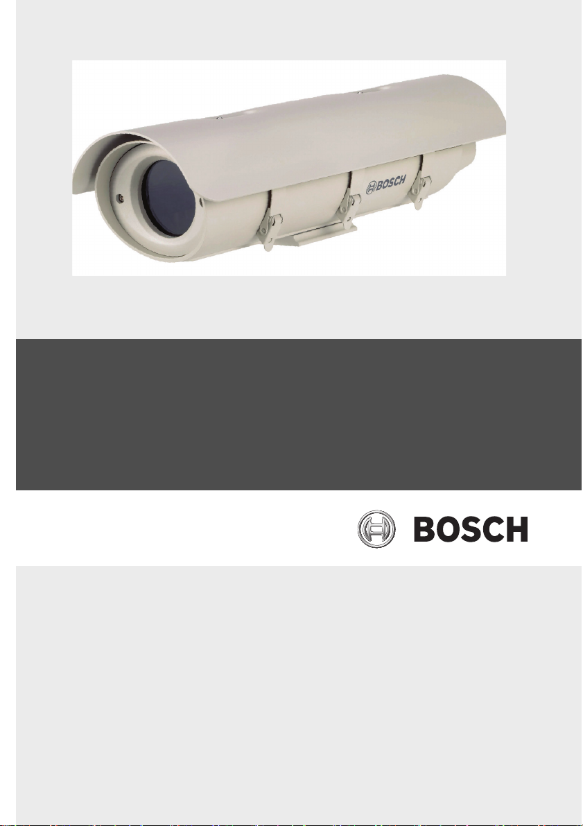
4 Beschreibung
Die Gehäuse der UHI/UHO Serie verfügen über ein
ansprechendes Design für den Einsatz innerhalb und außerhalb
von Gebäuden. Diese Gehäuse entsprechen den
Kundenanforderungen hinsichtlich Aussehen, Kosteneffizienz
und einfacher Installation. Eine Beschreibung der Modelle für
den Inneneinsatz finden Sie in Tabelle 4.1.
Heizelement und Lüfter arbeiten bei allen Modellen mit 50/
60 Hz. Die 4-poligen Modelle verfügen über einen 4-poligen
Stecker und einen BNC-Anschluss anstelle der
Kabeldurchführungshalterungen.
Für Zubehör verwendete Abkürzungen:
HE = Heizelement, L = Lüfter, SB = Sonnenblende
F.01U.167.418 | 3.0 | 2010.04 Benutzerhandbuch Bosch Secuurity Systems, Inc.
Page 19
UHI/UHO Serien Beschreibung | de 19
UHI-OG-O UHI-OGS-O
Installiertes Zubehör nicht zutreffend
Spannungsbereich/Leistung nicht zutreffend
Nennspannung der Kamera 24/120/230 VAC
Max. Kamera-/Objektivgröße (HxBxT) 91 x 81 x 262 mm
Tabelle 4.1 Geräte für Inneneinsatz
UHO-HGS-10 UHO-HBGS-10UHO-HBPS-10
Installiertes Zubehör HE, SB HE, L, SB HE, L, SB, 4-
polig
Spannungsbereich/Leistung 21,6 bis 25,4 VAC/40 W
Nennspannung der Kamera 24 VAC
Max. Kamera-/Objektivgröße
91 x 81 x 262 mm
(HxBxT)
Tabelle 4.2 Geräte für Außeneinsatz, 24 V
UHO-HBGS-60
Installiertes Zubehör HE, L, SB
Spannungsbereich/Leistung 108 bis 132 VAC/45 W
Nennspannung der Kamera 120 V
Max. Kamera-/Objektivgröße (HxBxT) 91 x 81 x 262 mm
Tabelle 4.3 Gerät für Außeneinsatz, 120 V
UHO-HGS-50 UHO-HPS-50 UHO-HBGS-50 UHO-HBPS-50
Installiertes
Zubehör
Spannungsber
HE, SB HE, SB, 4-
polig
HE, L, SB HE, L, SB, 4-
polig
198 bis 254 VAC/40 W 198 bis 254 VAC/45 W
eich/Leistung
Nennspannun
230 VAC
g der Kamera
Max. Kamera-/
91 x 81 x 262 mm
Objektivgröße
(HxBxT)
Tabelle 4.4 Geräte für Außeneinsatz, 230 V
Bosch Secuurity Systems, Inc. Benutzerhandbuch F.01U.167.418 | 3.0 | 2010.04
Page 20
20 de | Installation UHI/UHO Serien
5 Installation
VORSICHT!
Die Installation darf nur von qualifiziertem Wartungspersonal
gemäß den jeweils zutreffenden Elektrovorschriften ausgeführt
werden.
VORSICHT!
Die ordnungsgemäße und sichere Montage der Geräte muss an
einer Tragstruktur erfolgen, die das Gewicht des Geräts tragen
kann. Wählen Sie Halterungen und Schwenk-/
Neigevorrichtungen (nicht im Lieferumfang enthalten) mit
äußerster Sorgfalt aus. Das Gewicht der Geräte und die
Beschaffenheit der Montageoberfläche müssen ebenfalls
berücksichtigt werden.
5.1 Erforderliche Werkzeuge
– Kleiner Schlitzschraubendreher
– Kreuzschlitzschraubendreher (Nr. 1)
– Justierbarer Schraubenschlüssel
– Drahtzange/Abisolierzange/Crimpzange
5.2 Kameraanforderungen
Für den Einbau in das Gehäuse müssen die Kameras den
Anforderungen in Tabelle 5.1 entsprechen.
Umgebungstemperatur 0 °C bis +50 °C
Leistungsaufnahme 10 W (max.)
Spannung für
Niederspannungsgeräte
Spannung für
Hochspannungsgeräte
Gewicht ohne Objektiv Max. 450 g
Gewicht mit Objektiv Max. 1 kg
Betriebstemperatur –20 °C bis +50 °C
Tabelle 5.1 Kameras – Spezifikationen
F.01U.167.418 | 3.0 | 2010.04 Benutzerhandbuch Bosch Secuurity Systems, Inc.
12 VAC bis 28 VAC, +12 VDC bis
+30 VDC
100 VAC bis 240 VAC
Page 21
UHI/UHO Serien Installation | de 21
5.3 Kabelanforderungen
5.3.1 Videoübertragung (Koax)
Kabelausführung
Länge < 300 m
Länge < 600 m
Kabeldurchmesser (außen) 4,6 mm bis 7,9 mm
Kabelform Rund
Kabelschirm >93 % Kupfergeflecht
Innenleiter Mehrdrähtiges Kupfer oder
DC-Widerstand
RG-59/U
RG-11/U
Kabelimpedanz 75 Ohm
Prüfstelle UL
Umgebungsbedingungen Außeneinsatz
Temperaturbereich +80 °C oder höher
Referenztyp Belden 9259
Tabelle 5.2 Videokabel – Spezifikationen
RG-59/U
RG-11/U
Massivkupfer
<15 Ohm/1000 m
<6 Ohm/1000 m
5.3.2 Netzkabel
Kabelausführung 3 x 18 AWG
Kabeldurchmesser (außen) 4,6 bis 7,9 mm
Kabelform Rund
Leiter 3 oder 2
Nennspannung 300 V
Prüfstelle UL/C.S.A., UL VW-1
Umgebungsbedingungen Außeneinsatz
Temperaturbereich +105 °C oder höher
Referenztyp Belden 19509, 3-adrig;
Northwire FSJT183-81K, 3-adrig
Tabelle 5.3 Netzkabel für USA und Kanada – Spezifikationen
Bosch Secuurity Systems, Inc. Benutzerhandbuch F.01U.167.418 | 3.0 | 2010.04
Page 22

22 de | Installation UHI/UHO Serien
Kabelausführung H05RN-F 3 G 0.75;
H05RN-F 3 G 1.00
Kabeldurchmesser (außen) 4,6 bis 7,9 mm
Kabelform Rund
Leiter 3 oder 2
Nennspannung 300 V
Prüfstelle VDE
Umgebungsbedingungen Außeneinsatz
Referenztyp Ölflex Gummikabel 1600 252;
Ölflex Gummikabel 1600 253
Tabelle 5.4 Netzkabel für Europa – Spezifikationen
5.3.3 Kabel für Objektivsteuerung
Kabelausführung Geschirmtes mehradriges
Kabel
Kabeldurchmesser (außen) 4,6 bis 7,9 mm
Kabelform Rund
Kabelschirm Gesamtschirm
Leiter 4 und 8
Leiterart Verseilt, 20 bis 16 AWG
Isolierhülle Farbcodiert
Tabelle 5.5 Kabel für Objektivsteuerung – Spezifikationen
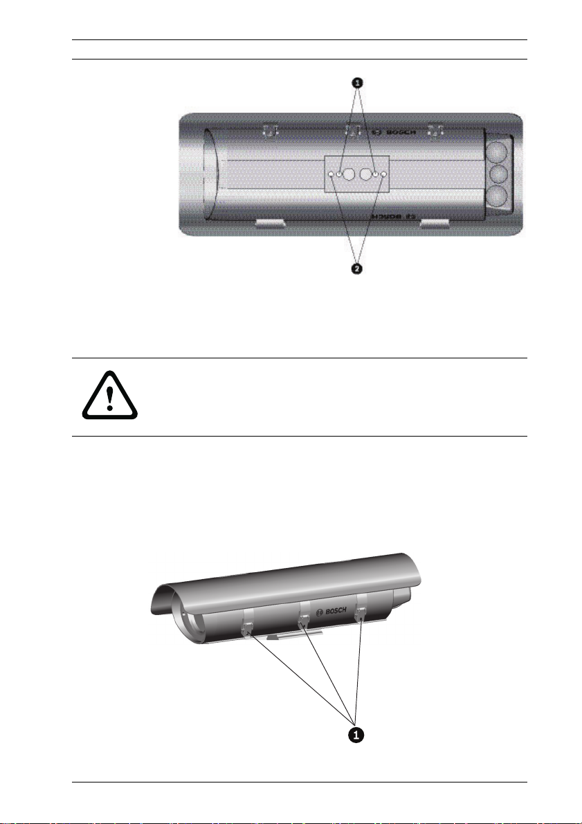
5.4 Gehäusemontage
1. Montieren Sie das Gehäuse mit den beiden 1/420 x 0,50 Zoll-Schrauben und 1/4 Zoll-Federscheiben an
eine Halterung oder Schwenk-/Neigevorrichtung. Die
Federscheiben müssen verwendet werden, um eine
sichere Schraubenführung zu gewährleisten.
2. Die ganz außen liegenden Öffnungen mit Gewinde 1/4-20
dienen zur Befestigung an Durchführungshalterungen. Die
ganz innen liegenden Öffnungen mit Gewinde 1/4-20
dienen zur Befestigung an anderen Halterungen und
Schwenk-/-Neigevorrichtungen (siehe Bild 5.1).
F.01U.167.418 | 3.0 | 2010.04 Benutzerhandbuch Bosch Secuurity Systems, Inc.
Page 23
UHI/UHO Serien Installation | de 23
Bild 5.1 Gewindeöffnungen zur Montage mit rückseitigen Anschlüs-
sen oder mit Kabeldurchführung
5.5 Öffnen der Abdeckung
WARNUNG!
Das Heizelement wird während des Betriebs HEISS – NICHT
BERÜHREN. Schalten Sie das Heizelement bei Arbeiten an der
Kamera immer AUS.
Öffnen Sie die Abdeckung, indem Sie die drei Verschlüsse an
der Gehäuseseite öffnen (siehe Bild 5.2). Falls die optionalen
manipulationssicheren Schrauben angebracht sind, müssen Sie
diese vor dem Öffnen der Verschlüsse mit Hilfe des
mitgelieferten Schraubenschlüssels entfernen.
Bild 5.2 Entriegeln der Abdeckung
Bosch Secuurity Systems, Inc. Benutzerhandbuch F.01U.167.418 | 3.0 | 2010.04
Page 24
24 de | Installation UHI/UHO Serien
5.6 Installieren von Kamera/Objektiv
1. Entfernen Sie die beiden Schrauben, mit denen der
Kameraeinsatz am Gehäuse befestigt ist, und entfernen Sie
dann den Einsatz vom Gehäuse.
2. Falls Sie die Durchführungshalterung verwenden, lesen Sie
die Informationen in Abschnitt 5.7.3 Kabeldurchführung,
Seite 27.
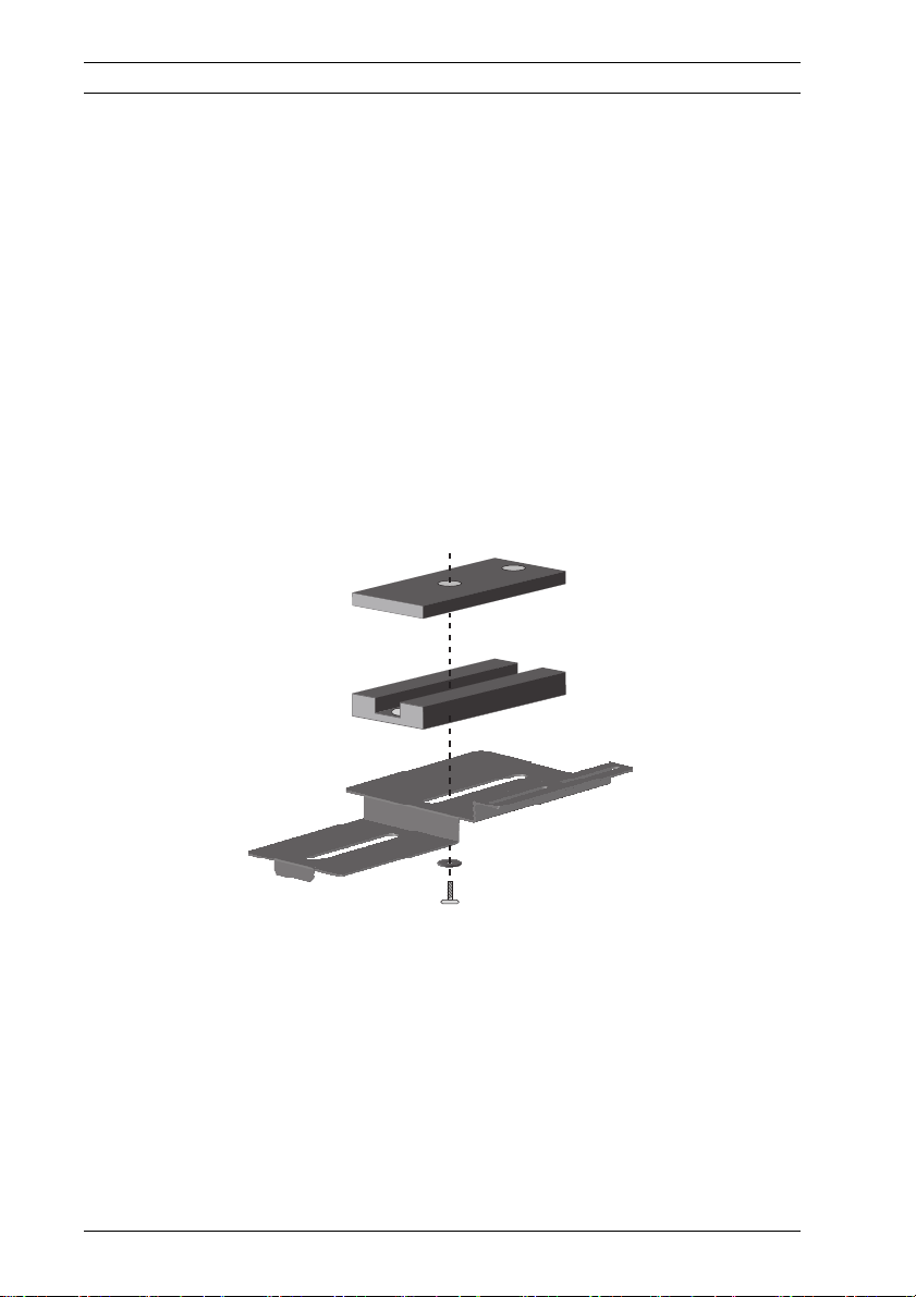
3. Installation von Kameras mit Zoomobjektiv:
– Befestigen Sie das Objektiv an der Kamera.
– Montieren Sie die Kamera und das Objektiv mit den
verschiedenen 1/4-20 Schrauben und geeigneten
4 mm- bzw. 9 mm-Abstandhaltern (im Lieferumfang
enthalten) am Kameraeinsatz. Dieser Kameraeinsatz
ist bereits zusammengebaut.
Bild 5.3 Abstandhalter zur Montage von Zoomobjektiv und Kamera
F.01U.167.418 | 3.0 | 2010.04 Benutzerhandbuch Bosch Secuurity Systems, Inc.
Page 25
UHI/UHO Serien Installation | de 25
4. Montage von Kameras mit Festobjektiven in allen
Gehäusetypen:
– Befestigen Sie das Objektiv an der Kamera.
– Montieren Sie die Kamera mit Hilfe einer Kombination
aus 4 mm- und 9 mm-Abstandhaltern am optionalen
Kameraeinsatz des Typs A. (Verwenden Sie
verschiedene Kombinationen der Abstandhalter,
damit das Kameraobjektiv mittig im Fenster
ausgerichtet ist.) Befestigen Sie die Kamera und den
Abstandhalter mit der 1/4-20 x 5/8 Zoll-Schraube und
der großen flachen Unterlegscheibe am
Kameraeinsatz (siehe Bild 5.4).
– Schieben Sie den Einsatz mit der Kamera und dem
Objektiv dann in die Aussparung bei den
Gehäusescharnieren (siehe Bild 5.3). Schieben Sie die
gesamte Baugruppe nach vorne bis ca. 5 mm vor das
Fenster. Stecken Sie die Schrauben in die dafür
vorgesehenen Bohrungen, und ziehen Sie sie fest.
Bild 5.4 Optionaler Kameraeinsatz des Typs A für Festobjektivka-
Bild 5.5 Einschieben des Einsatzes mit Kamera und Objektiv in die
Bosch Secuurity Systems, Inc. Benutzerhandbuch F.01U.167.418 | 3.0 | 2010.04
mera
Aussparung
Page 26

26 de | Installation UHI/UHO Serien
5.7 Anschließen von Kamera/Objektiv
Eine Beschreibung zu den Modellen UHO-HBPS-10, UHO-HPS50 und UHO-HBPS-50 finden.
WARNUNG!
Verwenden Sie zum Anschließen von Kamera und Objektiv
ausschließlich Kabel, die den Spezifikationen in Section
Kabelanforderungen entsprechen.
5.7.1 Halterungen
Die 3/8 Zoll-NPT-Halterung ist für ein rundes Kabel mit einem
Durchmesser zwischen 4,0 mm und 7,0 mm geeignet.
Die beiden größeren 1/2 Zoll-NPT-Halterungen sind für Kabel
mit einem Durchmesser zwischen 6,5 mm und 10,5 mm
geeignet.
VORSICHT!
Alle Halterungen müssen stets sorgfältig angezogen werden,
damit sie wasserdicht abschließen. Falls Sie die Halterung nicht
fest genug anziehen, kann Wasser in das Gehäuse gelangen und
die Kamera und das Objektiv beschädigen. Bei Verwendung
eines Dichtungsmittels muss ein neutral vernetzendes
Dichtungsmittel gewählt werden. Dichtungsmittel, die beim
Aushärten Essigsäure freisetzen, können die Kameraelektronik
beschädigen. Es wird empfohlen, für die Verkabelung außerhalb
der hinteren Endabdeckung Tropfschlaufen zu verwenden.
5.7.2 Kabelkanal
Diese Gehäuse erlauben die direkte Anbringung eines
Kabelkanals.
1. Entfernen Sie die Schutzkappen von der Rückseite, und
befestigen Sie den Kabelkanal und die
Kabelkanalhalterungen direkt an der hinteren
Gehäuseabdeckung. Die Öffnungen sind für Halterungen
für 3/8 Zoll-NPT- oder 1/2 Zoll-NPT-Kabelkanäle ausgelegt.
2. Alle ungenutzten Öffnungen müssen mit den Schutzkappen
versehen werden, die mit dem Gehäuse geliefert wurden.
F.01U.167.418 | 3.0 | 2010.04 Benutzerhandbuch Bosch Secuurity Systems, Inc.
Page 27
UHI/UHO Serien Installation | de 27
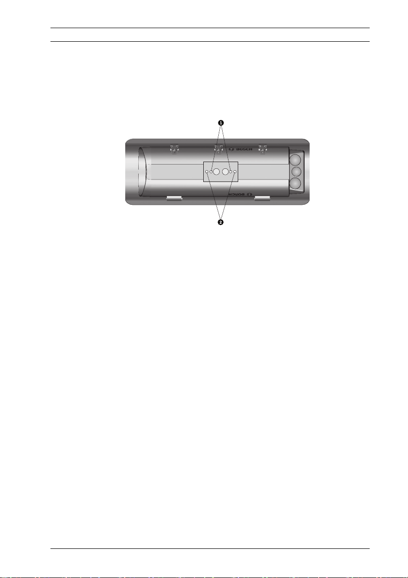
5.7.3 Kabeldurchführung
Zur Kabeldurchführung durch den Fuß des Gehäuses stehen
Kabeldurchführungshalterungen zur Verfügung.
1. Entfernen Sie vor der Kameramontage die beiden Kappen,
die sich im Gehäuseinneren befinden (siehe Bild 5.6).
Bild 5.6 Position der Öffnungen für die Kabeldurchführung
2. Schrauben Sie die beiden 3/8 Zoll-NPT-Halterungen in den
Fuß des Gehäuses.
3. Ziehen Sie die Kabel durch die Halterungen in das
Gehäuse. Ziehen Sie die Halterung mit einem Drehmoment
von 4,0 Nm bis 4,5 Nm fest. Dieses Drehmoment
entspricht etwa 1 bis 1,5 Drehungen nach dem Punkt, an
dem die Halterung am Kabel zu greifen beginnt. Falls Sie
die Halterung nicht fest genug anziehen, führt dies zu
Wasser-eintritt und Beschädigung aller elektronischen
Teile.
4. Montieren Sie den Fuß an der oberen Gehäusehalterung.
5. Vergewissern Sie sich, dass die Öffnungen in der hinteren
Abdeckung mit den dafür vorgesehenen Gummikappen
verschlossen sind. Drücken Sie die Kappen hinein, bis sie
bündig abschließen, und lassen Sie sie dann los.
Bosch Secuurity Systems, Inc. Benutzerhandbuch F.01U.167.418 | 3.0 | 2010.04
Page 28

28 de | Installation UHI/UHO Serien
5.7.4 Netzstromanschlüsse
Die Stromversorgung zum Gerät im Gehäuse erfolgt über Kabel
vom Typ UL Standard SJ (oder besser), die für den
Außeneinsatz geeignet sind. Die Installation muss NEC400-4
(CEC-Vorschrift 4-010) entsprechen und mit OUTDOOR, W,
oder W-A gekennzeichnet sein. Orientieren Sie sich bei der
Auswahl der geeigneten Kabellänge für 24 Volt-Kameras an den
Angaben in der Tabelle mit den empfohlenen maximalen
Kabellängen.
Leiterquerschnitt
2
mm
Leiterquerschnitt
AWG
Entfernung m
0,5 20 27
1 18 42
1,5 16 67
2,5 14 108
4 12 172
Tabelle 5.6 Empfohlene maximale Kabellängen für Gehäuse mit 24 Volt-
Kameras, Heizelementen und Lüftern
Für Leiterquerschnitte über 2,5 mm2 (AWG 14) wird ein Spleiß
für die Verbindung mit dem Anschlussblock benötigt.
1. Falls Sie die Installation mit Kabeldurchführung ausführen,
können Sie diesen Schritt überspringen. Montieren Sie
eine der beiden großen 1/2 Zoll-NPT-Halterungen in eine
der Öffnungen in der hinteren Abdeckung.
2. Führen Sie das Netzkabel durch die Halterung in der
hinteren Abdeckung oder durch eine der
Durchführungshalterungen im Fuß.
Der Anschlussblock ist für Kabel mit einem Querschnitt von 0,5
bis 2,5 mm
2
(AWG 20-14) geeignet. Bei Verwendung von
stärkeren Kabeln müssen Sie das Kabel für den Anschluss am
Anschlussblock mit einem dünneren Kabel verspleißen.
Der Spleiß muss möglicherweise durch eine Anschlussdose
geführt werden, falls er nicht durch die Halterung verläuft.
F.01U.167.418 | 3.0 | 2010.04 Benutzerhandbuch Bosch Secuurity Systems, Inc.
Page 29
UHI/UHO Serien Installation | de 29
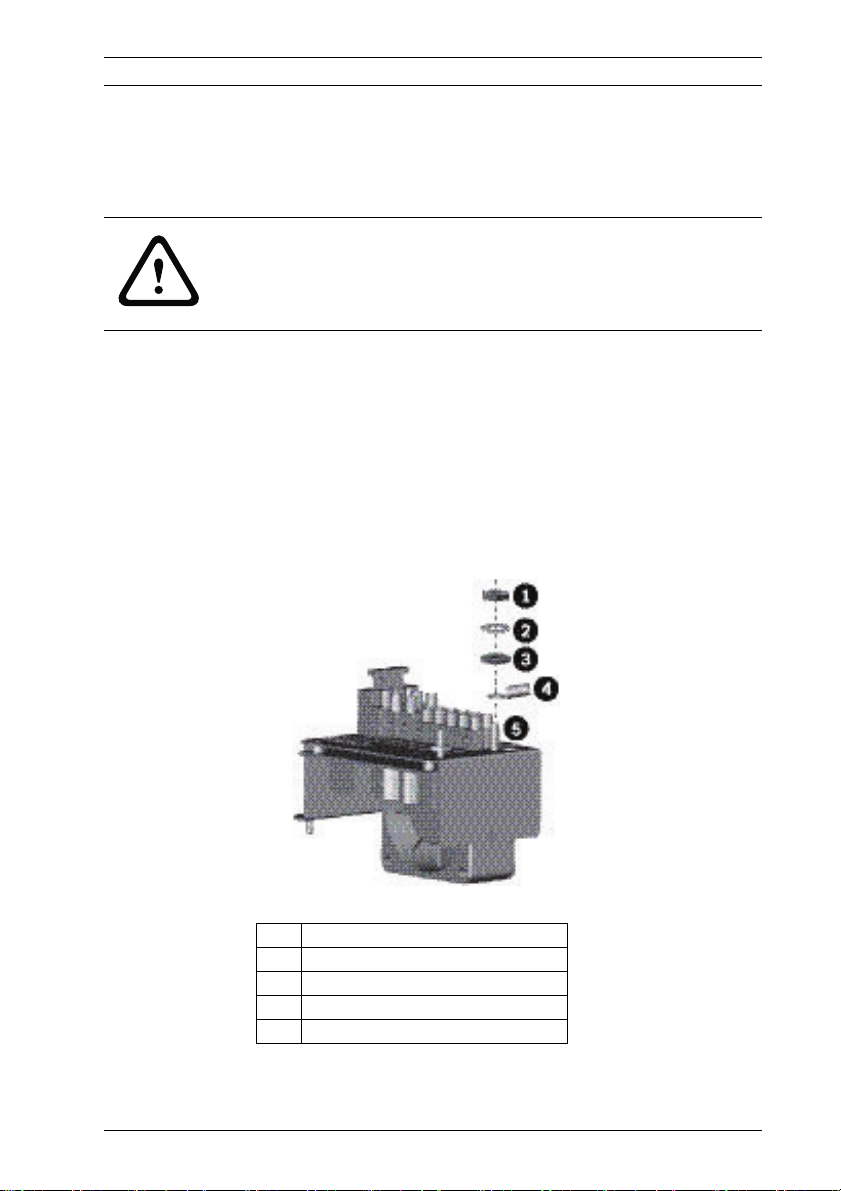
1. Schließen Sie den Schutzleiter (Erdung) an:
Zum Anschließen des externen Schutzleiters an den
Erdungsanschluss an der entsprechenden Platinenklemme ist
eine Anschlussfahne vorgesehen (siehe Bild 5.7).
VORSICHT!
Zur Einhaltung der Sicherheitsvorschriften muss der externe
Schutzleiter stets an den Haupterdungsanschluss
angeschlossen sein.
– Zum Anschließen des externen Schutzleiters
entfernen Sie die Mutter, die Unterlegscheiben und
die Anschlussfahne für das externe Erdungskabel vom
Erdungsanschluss.
– Isolieren Sie das Kabel ab, und klemmen Sie das
externe Erdungskabel in die Anschlussfahne.
– Bringen Sie die Erdungsanschlüsse in der in Bild 5.7
dargestellten Reihenfolge wieder an.
Bild 5.7 Schutzerdung
1 Mutter
2 Sicherungsscheibe
3 Flache Unterlegscheibe
4 Externe Anschlussfahne
5 Externer Erdungsanschluss
Bosch Secuurity Systems, Inc. Benutzerhandbuch F.01U.167.418 | 3.0 | 2010.04
Page 30

30 de | Installation UHI/UHO Serien
HINWEIS!
Schließen Sie den externen Schutzleiter gemäß den
Anforderungen der Norm NEC/CEC an.
1. Ziehen Sie überschüssiges Kabel aus dem Gehäuse, und
ziehen Sie die Halterung mit einem Drehmoment von
8,5 Nm bis 9,0 Nm fest. Dieses Drehmoment entspricht
etwa 1 bis 1,5 Drehungen nach dem Punkt, an dem die
Halterung am Kabel zu greifen beginnt.
VORSICHT!
Alle Halterungen müssen sorgfältig angezogen werden, damit
sie wasserdicht abschließen. Falls Sie eine oder mehrere
Halterungen nicht fest genug anziehen, kann Wasser in das
Gehäuse gelangen und elektronische Teile, die Kamera und das
Objektiv beschädigen.
2. Schließen Sie die Stromversorgungskabel an den
Anschlussblock an (siehe Bild 5.7). Entfernen Sie
mindestens 6 mm und höchstens 8 mm Isolierung von der
Kabellitze. Gehen Sie dabei vorsichtig vor. Die Kabellitze
darf nicht beschädigt werden.
3. Schneiden Sie bei Kameramodellen mit 120 VAC und
230 VAC das Stromkabel ab. Lassen Sie jedoch genug
Kabel für die Verbindung zum Anschlussblock. Entfernen
Sie mindestens 6 mm und höchstens 8 mm Isolierung von
der Kabellitze. Gehen Sie dabei vorsichtig vor. Die
Kabellitze darf nicht beschädigt werden. Verbinden Sie
diese Kabellitzen mit den Anschlüssen des
Anschlussblocks (siehe Bild 5.8).
F.01U.167.418 | 3.0 | 2010.04 Benutzerhandbuch Bosch Secuurity Systems, Inc.
Page 31

UHI/UHO Serien Installation | de 31
FUSE
L
L
L
N
N
N
G
G
G
1 2 x
L
N
Bild 5.8 Schaltplan des Anschlussblocks
1 Zur Kamera 7 Erdungskabel zur
2 Zum Zubehör 8 Erdungsstift
3 BNC-Kabel zur Kamera 9 Netzstrom-anschluss
4 Objektiv-verkabelung 10 Videoeingang
5Erdungsanschluss für
Gehäuse-oberseite
Gehäuseunterseite
11 Objektiv
Stromeingang
6 Anschluss für Erdungsprüfung
NICHT trennen
Stift Farbe Anschluss
N Blau Stromanschluss
L Braun Stromanschluss
G Grün S (Schutzleiter)
Bosch Secuurity Systems, Inc. Benutzerhandbuch F.01U.167.418 | 3.0 | 2010.04
Page 32

32 de | Installation UHI/UHO Serien
Die Angaben empfohlener Positionen und Anschlussmethoden
im Anordnungs- und Installationsschaltplan entsprechen den
Normen NEC, ANSI/NFPA 70.
VORSICHT!
Zum Schutz des Geräts muss der Nebenstromkreisschutz mit
einer maximalen Sicherungsbemessung von 16 A abgesichert
sein. Dies muss gemäß NEC 800 (CEC Abschnitt 60) erfolgen.
1. Vergewissern Sie sich bei Einheiten mit Heizelement bzw.
Lüfter, dass die Kabel von Heizelement und Lüfter
weiterhin fest mit dem Anschlussblock verbunden sind.
2. Das BNC-Kabel muss sich in sicherem Abstand zur
Netzstromversorgung und dem Heizelement befinden.
5.8 Videokoaxverbindung
Eine Beschreibung zu den Modellen UHO-HBPS-10, UHO-HPS50 und UHO-HBPS-50.
1. Montieren Sie eine 1/2 Zoll-NPT-Halterung in einer freien
Öffnung der hinteren Abdeckung.
VORSICHT!
Verwenden Sie für Videokoaxverbindungen ausschließlich
Kabel, die den Spezifikationen in Section Kabelanforderungen
entsprechen.
1. Führen Sie das Videokoaxkabel durch eine der in Schritt
montierten Halterungen oder durch eine der
Durchführungshalterungen im Fuß.
2. Verbinden Sie den BNC-Anschluss mit dem Koaxkabel, und
schließen Sie ihn an die Kamera an.
F.01U.167.418 | 3.0 | 2010.04 Benutzerhandbuch Bosch Secuurity Systems, Inc.
Page 33

UHI/UHO Serien Installation | de 33
VORSICHT!
Alle Halterungen müssen stets sorgfältig angezogen werden,
damit sie wasserdicht abschließen. Falls Sie die Halterung nicht
fest genug anziehen, kann Wasser in das Gehäuse gelangen und
die Kamera und das Objektiv beschädigen. Bei Verwendung
eines Dichtungsmittels muss ein neutral vernetzendes
Dichtungsmittel gewählt werden. Dichtungsmittel, die beim
Aushärten Essigsäure freisetzen, können die Kameraelektronik
beschädigen. Es wird empfohlen, für die Verkabelung außerhalb
der hinteren Endabdeckung Tropfschlaufen zu verwenden.
3. Ziehen Sie überschüssiges Kabel aus dem Gehäuse, und
ziehen Sie die Halterung mit einem Drehmoment von
8,5 Nm bis 9,0 Nm fest. Dieses Drehmoment entspricht
etwa 1 bis 1,5 Drehungen nach dem Punkt, an dem die
Halterung am Kabel zu greifen beginnt.
5.9 Anschließen des Objektivs
1. Montieren Sie die 3/8 Zoll-NPT-Halterung in der mittleren
Öffnung der hinteren Abdeckung.
VORSICHT!
Verwenden Sie zum Anschließen von Kameras und Objektiven
ausschließlich Kabel, die den Spezifikationen in Section
Kabelanforderungen entsprechen.
2. Wenn Sie ein Zoomobjektiv installieren, führen Sie das
Kabel für die Objektivsteuerung durch die letzte Halterung
auf der Gehäuserückseite. Verbinden Sie die Objektivkabel
mit dem Anschlussstecker für das Objektiv, und schließen
Sie diesen an das Objektiv an. Wenn kein Anschlussstecker
verfügbar ist, verbinden Sie die Kabel direkt mit dem
Objektivkabel.
Bosch Secuurity Systems, Inc. Benutzerhandbuch F.01U.167.418 | 3.0 | 2010.04
Page 34

34 de | Installation UHI/UHO Serien
VORSICHT!
Alle Halterungen müssen stets sorgfältig angezogen werden,
damit sie wasserdicht abschließen. Falls Sie die Halterung nicht
fest genug anziehen, kann Wasser in das Gehäuse gelangen und
die Kamera und das Objektiv beschädigen. Bei Verwendung
eines Dichtungsmittels muss ein neutral vernetzendes
Dichtungsmittel gewählt werden. Dichtungsmittel, die beim
Aushärten Essigsäure freisetzen, können die Kameraelektronik
beschädigen. Es wird empfohlen, für die Verkabelung außerhalb
der hinteren Endabdeckung Tropfschlaufen zu verwenden.
3. Ziehen Sie überschüssiges Kabel aus dem Gehäuse, und
ziehen Sie die Halterung mit einem Drehmoment von
8,5 Nm bis 9,0 Nm fest. Dieses Drehmoment entspricht
etwa 1 bis 1,5 Drehungen nach dem Punkt, an dem die
Halterung am Kabel zu greifen beginnt.
4. Wenn Sie eine Schwenk-/Neigevorrichtung mit
Kabeldurchführung verwenden, führen Sie das
Funktionskabel der Kamera bzw. des Objektivs durch die
linke Halterung an der Gehäuserückwand. Verkabeln Sie
die erforderlichen Funktionselemente.
Hinweise für den ordnungsgemäßen Anschluss finden Sie in der
Spezifikation auf dem Objektivkabel.
5.10 Justieren von Kamera/Objektiv
Überprüfen Sie vor der Endmontage, ob die Kamera und das
Objektiv ordnungsgemäß funktionieren. Stellen Sie den
Kamerafokus und die Blende entsprechend ein. Informationen
hierzu finden Sie im Installationshandbuch der Kamera.
F.01U.167.418 | 3.0 | 2010.04 Benutzerhandbuch Bosch Secuurity Systems, Inc.
Page 35

UHI/UHO Serien Installation | de 35
5.11 Endmontage
1. Verschließen Sie alle ungenutzten Öffnungen in der
hinteren Abdeckung mit den mitgelieferten Schutzkappen.
2. Platzieren Sie die Kamera zusammen mit der Halterung im
Gehäuse.
3. Schieben Sie den Einsatz mit der Kamera und dem
Objektiv dann in die Aussparung bei den
Gehäuseverschlüssen (siehe Bild 5.3).
4. Stecken Sie die Schrauben in die dafür vorgesehenen
Bohrungen, und ziehen Sie sie fest.
5. Schließen Sie die Abdeckung, und sichern Sie die
Verschlüsse.
6. Das Gehäuse wird zusammen mit manipulationssicheren
Schrauben geliefert, die Sie bei Bedarf anbringen können.
Falls Sie diese verwenden möchten, sichern Sie die
Verschlüsse mit Hilfe des Schraubenschlüssels für
manipulationssichere Schrauben und den drei Schrauben.
5.12 Sonnenblende
1. Lösen Sie die beiden Schrauben (M4 x 10), die sich auf der
Gehäuseoberseite befinden.
2. Schieben Sie die Sonnenblende in die gewünschte
Position. Sie können sie in einem Bereich von ca. 50 mm
anpassen.
3. Fixieren Sie dann die Sonnenblende in dieser Position,
indem Sie die Schrauben anziehen.
4. Falls Sie die Sonnenblende entfernen oder nicht
anbringen, verschließen Sie die beiden
Schraubenöffnungen mit Hilfe der im Lieferumfang des
Teilesatzes enthaltenen Schutzkappen.
Bosch Secuurity Systems, Inc. Benutzerhandbuch F.01U.167.418 | 3.0 | 2010.04
Page 36

36 de | UHO-HBPS-10, -50 und UHO-HPS-50 UHI/UHO Serien
5.13 Austauschen der Sicherung
1. Zum Austauschen einer Sicherung ziehen Sie am oberen
Teil des Sicherungshalters.
2. Ersetzen Sie die Sicherung durch eine Sicherung mit
derselben Sicherungsbemessung. Bei der Sicherung
handelt es sich um eine Glaskolben-Sicherung (träge,
5 mm x 20 mm).
Kameraspannung Sicherungsbemessung
24VAC 4A, 250VAC
120VAC 2A, 250VAC
230VAC 2A, 250VAC
Im Gehäuseinneren befindet sich eine Ersatzsicherung.
6 UHO-HBPS-10, -50 und UHO-HPS-50
6.1 Anschließen von Kamera/Objektiv
Die Installation dieser Modelle erfolgt mit Ausnahme der unten
aufgeführten Punkte gemäß der Beschreibung in
Abschnitt 5 Installation.
VORSICHT!
Verwenden Sie für UHO-HBPS-10 Modelle nur Stromquellen mit
24 VAC. Diese Modelle verfügen über Buchsen, um zu
verhindern, dass sie mit dem Anschluss verbunden werden, der
mit den UHO-HPS-50 und UHO-HBPS-50 Modellen für 230 VAC
geliefert wird. Vergewissern Sie sich, dass an den
Anschlussstecker kein Wechselstrom von 230 V angelegt wird.
Alle Stromanschlüsse sind für 4-polige Stecker ausgelegt.
Kabel-anforderungen für den 4-poligen Anschluss:
6,0 mm bis 12,0 mm
F.01U.167.418 | 3.0 | 2010.04 Benutzerhandbuch Bosch Secuurity Systems, Inc.
Page 37

UHI/UHO Serien UHO-HBPS-10, -50 und UHO-HPS-50 | de 37
1. Schneiden Sie bei Kameramodellen mit 230 VAC das
Stromkabel ab. Lassen Sie jedoch genug Kabel für die
Verbindung zum Anschlussblock. Entfernen Sie mindestens
6 mm und höchstens 8 mm Isolierung von der Kabellitze.
Gehen Sie dabei vorsichtig vor. Die Kabellitze darf nicht
beschädigt werden.
2. Führen Sie das Stromkabel durch die rückwärtige
Abdeckung und die Zugentlastungsklemme (siehe
Bild 6.1).
Bild 6.1 Stecker/Buchse, 4-polig
1. Der Anschlussblock dieser Geräte ist für Kabel mit einem
Querschnitt von 0,5 bis 2,5 mm2 (AWG 20-14) geeignet.
Bei Verwendung von stärkeren Kabeln müssen Sie das
Kabel für den Anschluss am Anschlussblock mit einem
dünneren Kabel verspleißen.
2. Verbinden Sie das Stromkabel mit den Schraubklemmen
des Anschlusses (siehe Bild 6.1 und Tabelle 6.1).
Stift Funktion Farbe am Kabelbaum
1 Nullleiter Blau
2 Spannungsführend (AC) Braun
3 Kein Anschluss Nicht verwenden
4 Erde Grün/Gelb
Tabelle 6.1 4-poliger Kabelanschluss
Bosch Secuurity Systems, Inc. Benutzerhandbuch F.01U.167.418 | 3.0 | 2010.04
Page 38

38 de | Betrieb UHI/UHO Serien
6.2 Videokoaxverbindung
VORSICHT!
Verwenden Sie für Videokoaxverbindungen ausschließlich
Kabel, die den Spezifikationen in Section Kabelanforderungen
entsprechen.
1. An der Gehäuserückwand befindet sich der
Videoanschluss. Schließen Sie das Videokabel mit einem
BNC-Stecker an diesen Anschluss an.
2. Das Gerät verfügt über einen internen Videoanschluss.
Schließen Sie das BNC-Kabel an der Kamera an.
7 Betrieb
Bei diesen Gehäusen müssen lediglich die Kamera sowie das
Objektiv eingestellt werden. Weitere Einstellungen sind nicht
erforderlich.
8 Wartung
Außer der gelegentlichen Reinigung des Fensters sind keine
besonderen Wartungsarbeiten erforderlich. Das Fenster kann
mit Wasser oder jeder anderen nicht aggressiven Flüssigkeit
gereinigt werden.
F.01U.167.418 | 3.0 | 2010.04 Benutzerhandbuch Bosch Secuurity Systems, Inc.
Page 39

UHI/UHO Serien Explosionsdarstellung | de 39
9 Explosionsdarstellung
Bild 9.1 Explosionsdarstellung
Bosch Secuurity Systems, Inc. Benutzerhandbuch F.01U.167.418 | 3.0 | 2010.04
Page 40

40 de | Explosionsdarstellung UHI/UHO Serien
1. Sonnenblende (ZYB01) 7. Bodenplatte ohne Kabeldurchführung
(DZ4P1)
2. Obere Abdeckung (XG001) 8. Scheibe + Scheibenenteiser: 24 VAC
(BTQ24)
120 VAC (BJQ15)
23 VAC (BJQ23)
3. Untere Abdeckung mit
Verschlüssen,
Kanalausführung (XDF01)
9. Hauptheizelement:
24 VAC (JRP24)
120 VAC (JRP12)
230 VAC (JRP23)
4. Untere Abdeckung mit
Verschlüssen, 4-polige
Ausführung (XD4P1)
10.Halterung für UHI Serie (FZ001)
Halterung + Platine/24 VACHeizelement, kein Lüfter (FZP24)
Halterung + Platine/24 VACHeizelement, mit Lüfter (FPF24)
Halterung + Platine/230 VACHeizelement, kein Lüfter (FZP23)
Halterung + Platine/230 VACHeizelement, mit Lüfter (FPF23)
Halterung + Platine/120 VACHeizelement, mit Lüfter (FPF12)
5. Vorderer Scheibenhalter
(QG001)
11.Kameraeinsatz, Ausführung mit
Zoomobjektiv (SP001)
Kameraeinsatz, Typ A (SP002)
6. Bodenplatte mit
Kabeldurchführung (DZFT1)12.
Beutel mit Zubehör (nicht abgebildet)
(PJB01)
F.01U.167.418 | 3.0 | 2010.04 Benutzerhandbuch Bosch Secuurity Systems, Inc.
Page 41

UHI/UHO Series Table of Contents | en 41
Table of Contents
1Safety 43
1.1 Important Safety Instructions 43
1.2 Safety Precautions 46
1.3 Important Notices 46
1.4 Customer Support and Service 53
2 Unpacking 54
3Service 55
4 Description 55
5 Installation 56
5.1 Tools required 56
5.2 Camera requirements 57
5.3 Cable requirements 57
5.3.1 Video transmission (coaxial) 57
5.3.2 Input power cord 58
5.3.3 Lens control cable 58
5.4 Housing mounting 59
5.5 Opening the cover 60
5.6 Camera/Lens installation 60
5.7 Camera/Lens wiring 62
5.7.1 Fittings 62
5.7.2 Conduit 63
5.7.3 Feed-through Wiring 63
5.7.4 Power Connections 64
5.8 Video coax connection 68
5.9 Lens wiring 69
5.10 Camera/Lens adjustment 70
5.11 Final assembly 70
5.12 Sunshield 70
5.13 Fuse replacement 71
Bosch Security Systems, Inc. Installation Manua F.01U.167.418 | v3.0 | 2010.04
Page 42

42 en | Table of Contents UHI/UHO Series
6 UHO-HBPS-10, -50, and UHO-HPS-50 71
6.1 Camera/lens wiring 71
6.2 Video coax connection 73
7Operation 73
8 Maintenance 73
9 Exploded view 74
F.01U.167.418 | v3.0 | 2010.04 Installation Manual Bosch Security Systems, Inc.
Page 43

UHI/UHO Series Safety | en 43
1Safety
1.1 Important Safety Instructions
Read, follow, and retain for future reference all of the following
safety instructions. Heed all warnings on the unit and in the
operating instructions before operating the unit.
1. Cleaning - Unplug the unit from the outlet before cleaning.
Follow any instructions provided with the unit. It is
generally sufficient to use a dry cloth for cleaning, but a
moist lint-free cloth or leather shammy may also be used.
Do not use liquid cleaners or aerosol cleaners.
2. Heat sources - Do not install the unit near any heat
sources such as radiators, heaters, stoves, or other devices
(including amplifiers) that produce heat.
3. Ventilation - Any openings in the unit housing are provided
for ventilation to prevent overheating and ensure reliable
operation. Do not block or cover these openings. Do not
place the unit in an enclosure unless proper ventilation is
provided, or the manufacturer's instructions have been
adhered to.
4. Water - Do not use this unit near water, for example near a
bathtub, washbowl, sink, laundry basket, in a damp or wet
basement, near a swimming pool, in an outdoor
installation, or in any area classified as a wet location. To
reduce the risk of fire or electrical shock, do not expose
this unit to rain or moisture.
5. Object and liquid entry - Never push objects of any kind
into this unit through openings, as they may touch
dangerous voltage points or short out parts, which could
result in a fire or electrical shock. Never spill liquid of any
kind on the unit. Do not place objects filled with liquids,
such as vases or cups, on the unit.
6. Lightning - For added protection during a lightning storm,
or when leaving this unit unattended and unused for long
periods, unplug the unit from the wall outlet and
Bosch Security Systems, Inc. Installation Manual F.01U.167.418 | 3.0 | 2010.04
Page 44

44 en | Safety UHI/UHO Series
disconnect the cable system. This will prevent damage to
the unit from lightning and power line surges.
7. Control adjustment - Adjust only those controls specified
in the operating instructions. Improper adjustment of
other controls may cause damage to the unit. Use of
controls or adjustments, or performance of procedures
other than those specified, may result in hazardous
radiation exposure.
8. Overloading - Do not overload outlets and extension cords.
This can cause fire or electrical shock.
9. Power disconnect - Units with or without ON/OFF
switches have power supplied whenever the power cord is
inserted into the power source; however, the unit is
operational only when the ON/OFF switch is in the ON
position. The power cord is the main power disconnect
device for switching off the voltage for all units.
10. Power sources - Operate the unit only via the type of
power source indicated on the label. Before proceeding,
be sure to disconnect the power from the cable being
connected to the unit.
– For battery powered units, refer to the operating
instructions.
– For units supplied by an external power source, use
only the recommended or approved power supplies.
– For limited power source units, this power source
must comply with EN60950. Substitutions may
damage the unit or cause fire or shock.
– For 24 VAC units, voltage applied to the unit's power
input should not exceed +/- 10% or 21.6-26.4 VAC.
User-supplied wiring must comply with local electrical
codes (Class 2 power levels). Do not ground the
supply at the terminals or at the unit's power supply
terminals.
– If unsure of the type of power supply to use, contact
your dealer or local power company.
F.01U.167.418 | 3.0 | 2010.04 Installation Manual Bosch Security Systems, Inc.
Page 45

UHI/UHO Series Safety | en 45
11. Servicing - Do not attempt to service this unit yourself.
Opening or removing covers may expose you to dangerous
voltage or other hazards. Refer all servicing to qualified
service personnel.
12. Damage requiring service - Unplug the unit from the main
AC power source and refer servicing to qualified service
personnel when any damage to the equipment has
occurred, for example if:
– the power supply cord or plug is damaged
– exposure to moisture, water, and/or inclement
weather (rain, snow etc.)
– liquid has been spilled in or on the equipment
– an object has fallen into the unit
– the unit has been dropped or the unit cabinet is
damaged
– the unit exhibits a distinct change in performance
– the unit does not operate normally when the user
correctly follows the operating instructions.
13. Replacement parts - Be sure the service technician uses
replacement parts specified by the manufacturer, or that
they have the same characteristics as the original parts.
Unauthorized substitutions may cause fire, electrical
shock, or other hazards.
14. Safety check - Safety checks should be performed on
completion of service or repairs to the unit, to ensure that
the unit is in proper operating condition.
15. Installation - Install in accordance with the manufacturer's
instructions and in accordance with applicable local codes.
16. Attachments, changes, or modifications - Only use
attachments/accessories specified by the manufacturer.
Any change to or modification of the equipment not
expressly approved by Bosch could void the warranty or, in
the case of an authorization agreement, authority to
operate the equipment.
Bosch Security Systems, Inc. Installation Manual F.01U.167.418 | 3.0 | 2010.04
Page 46

46 en | Safety UHI/UHO Series
1.2 Safety Precautions
DANGER!
This symbol indicates an imminently hazardous situation such
as “Dangerous Voltage” inside the product. If not avoided, this
will result in an electrical shock, serious bodily injury, or death.
WARNING!
Indicates a potentially hazardous situation. If not avoided, this
may result in minor or moderate injury. Alerts the user to
important instructions accompanying the unit.
CAUTION!
Indicates a potentially hazardous situation. If not avoided, this
may result in damage to property or risk of damage to the unit.
NOTICE! This symbol indicates information or a company policy
that relates directly or indirectly to the safety of personnel or
protection of property.
1.3 Important Notices
Accessories - Do not place this unit on an unstable stand,
tripod, bracket, or mount. The unit may fall, causing serious
injury to persons and/or severe damage to the unit. Use only
with the cart, stand, tripod, bracket, or table specified by the
manufacturer. When a cart is used, exercise caution and care
when moving the cart/apparatus combination to avoid tipping it
over, which could result in injury. Quick stops, excessive force,
or uneven surfaces may cause the cart/unit combination to
overturn. Mount the unit in line with the manufacturer's
instructions.
All-pole power switch - Incorporate an all-pole power switch,
with a contact separation of at least 3 mm in each pole, into the
electrical installation of the building. If it is needed to open the
housing for servicing and/or other activities, use this all-pole
F.01U.167.418 | 3.0 | 2010.04 Installation Manual Bosch Security Systems, Inc.
Page 47

UHI/UHO Series Safety | en 47
switch as the main disconnect device for switching off the
voltage to the unit.
Camera grounding - When mounting the camera in potentially
damp environments, ensure the system is grounded through
the metal housing of the unit (see section: Connecting the
Power).
Camera signal - Protect the cable with a primary protector if
the camera signal is over 140 feet, in accordance with NEC800
(CEC Section 60).
Coax grounding:
– Ground the cable system if connecting an outside cable
system to the unit.
– Connect outdoor equipment to the unit's inputs only after
this unit has had its grounding plug connected to a
grounded outlet or its ground terminal is properly
connected to a ground source.
– Disconnect the unit's input connectors from outdoor
equipment before disconnecting the grounding plug or
grounding terminal.
– Follow proper safety precautions, such as grounding, for
any outdoor device connected to this unit.
U.S.A. models only - Section 810 of the National Electrical Code,
ANSI/NFPA No. 70, provides information regarding proper
grounding of the mount and supporting structure, grounding of
the coax to a discharge unit, size of grounding conductors,
location of discharge unit, connection to grounding electrodes,
and requirements for the grounding electrode.
Your Bosch product was developed and manufactured with
high-quality material and components that can be recycled and
reused. This symbol means that electronic and electrical
appliances that have reached the end of their service life must
be collected and disposed of separately from household waste
material. Separate collecting systems are usually in place for
disused electronic and electrical products. Please dispose of
these units at an environmentally compatible recycling facility,
in line with European Directive 2002/96/EC.
Bosch Security Systems, Inc. Installation Manual F.01U.167.418 | 3.0 | 2010.04
Page 48

48 en | Safety UHI/UHO Series
Environmental statement - Bosch has a strong commitment to
the environment. This unit has been designed to respect the
environment as much as possible.
Electrostatic-sensitive device - Take proper CMOS/MOS-FET
handling precautions to avoid electrostatic discharge.
NOTE: You must wear grounded wrist straps and observe
proper ESD safety precautions when handling the electrostaticsensitive printed circuit boards.
Fuse rating - For security protection of the device, the branch
circuit protection must be secured with a maximum fuse rating
of 16 A. This must be in accordance with NEC800 (CEC Section
60).
Grounding and polarization - This unit may be fitted with a
polarized alternating current line plug (a plug with one blade
wider than the other blade). This safety feature allows the plug
to fit into the power outlet in only one way. If unable to insert
the plug fully into the outlet, contact a locally certified
electrician to replace the obsolete outlet. Do not defeat the
safety purpose of the polarized plug.
Alternatively, this unit may be fitted with a 3-pole grounding
plug (a plug with a third pin for earth grounding). This safety
feature allows the plug to fit into a grounded power outlet only.
If unable to insert the plug into the outlet, contact a locally
certified electrician to replace the obsolete outlet. Do not
defeat the safety purpose of the grounding plug.
Moving - Disconnect the power before moving the unit. Move
the unit with care.
Permanently connected equipment - Incorporate a readily
accessible disconnect device in the building installation wiring.
Pluggable equipment - Install the socket outlet near the
equipment so it is easily accessible.
Power disconnect - Units have power supplied whenever the
power cord is inserted into the power source. The power cord
is the main power disconnect for all units.
Power lines - Do not locate the camera near overhead power
lines, power circuits, electrical lights, or anywhere where it
might come into contact with power lines, circuits, or lights.
F.01U.167.418 | 3.0 | 2010.04 Installation Manual Bosch Security Systems, Inc.
Page 49

UHI/UHO Series Safety | en 49
SELV
All the input/output ports are Safety Extra Low Voltage (SELV)
circuits. SELV circuits should only be connected to other SELV
circuits.
Because the ISDN circuits are treated like telephone-network
voltage, avoid connecting the SELV circuit to the Telephone
Network Voltage (TNV) circuits.
Video loss - Video loss is inherent to digital video recording;
therefore, Bosch Security Systems cannot be held liable for any
damage that results from missing video information. To
minimize the risk of lost digital information, Bosch Security
Systems recommends multiple, redundant recording systems,
and a procedure to back up all analog and digital information.
NOTICE! This is a class A product. In a domestic environment
this product may cause radio interference, in which case the
user may be required to take adequate measures.
FCC & ICES INFORMATION
(U.S.A. and Canadian Models Only)
This device complies with part 15 of the FCC Rules. Operation is
subject to the following conditions:
– this device may not cause harmful interference, and
– this device must accept any interference received,
including interference that may cause undesired operation.
Note
This equipment has been tested and found to comply with the
limits for a Class A digital device, pursuant to Part 15 of the
FCC Rules and ICES-003 of Industry Canada. These limits are
designed to provide reasonable protection against harmful
interference when the equipment is operated in a commercial
environment. This equipment generates, uses, and radiates
radio frequency energy and, if not installed and used in
accordance with the instruction manual, may cause harmful
interference to radio communications. Operation of this
equipment in a residential area is likely to cause harmful
Bosch Security Systems, Inc. Installation Manual F.01U.167.418 | 3.0 | 2010.04
Page 50

50 en | Safety UHI/UHO Series
interference, in which case the user will be required to correct
the interference at his expense.
Intentional or unintentional modifications not expressly
approved by the party responsible for compliance shall not be
made. Any such modifications could void the user's authority to
operate the equipment. If necessary, the user should consult
the dealer or an experienced radio/television technician for
corrective action.
The user may find the following booklet, prepared by the
Federal Communications Commission, helpful: How to Identify
and Resolve Radio-TV Interference Problems. This booklet is
available from the U.S. Government Printing Office,
Washington, DC 20402, Stock No. 004-000-00345-4.
INFORMATIONS FCC ET ICES
(modèles utilisés aux États-Unis et au Canada uniquement)
Ce produit est conforme aux normes FCC partie 15. La mise en
service est soumises aux deux conditions suivantes:
– cet appareil ne peut pas provoquer d'interférence nuisible
et
– cet appareil doit pouvoir tolérer toutes les interférences
auxquelles il est soumit, y compris les interférences qui
pourraient influer sur son bon fonctionnement.
AVERTISSEMENT: Suite à différents tests, cet appareil s’est
révélé conforme aux exigences imposées aux appareils
numériques de Classe A en vertu de la section 15 du règlement
de la Commission fédérale des communications des États-Unis
(FCC). Ces contraintes sont destinées à fournir une protection
raisonnable contre les interférences nuisibles quand l'appareil
est utilisé dans une installation commerciale. Cette appareil
génère, utilise et émet de l'energie de fréquence radio, et peut,
en cas d'installation ou d'utilisation non conforme aux
instructions, générer des interférences nuisibles aux
communications radio. L’utilisation de ce produit dans une
zone résidentielle peut provoquer des interférences nuisibles.
Le cas échéant, l’utilisateur devra remédier à ces interférences
à ses propres frais.
F.01U.167.418 | 3.0 | 2010.04 Installation Manual Bosch Security Systems, Inc.
Page 51

UHI/UHO Series Safety | en 51
Au besoin, l’utilisateur consultera son revendeur ou un
technicien qualifié en radio/télévision, qui procédera à une
opération corrective. La brochure suivante, publiée par la
Commission fédérale des communications (FCC), peut s’avérer
utile : « How to Identify and Resolve Radio-TV Interference
Problems » (Comment identifier et résoudre les problèmes
d’interférences de radio et de télévision). Cette brochure est
disponible auprès du U.S. Government Printing Office,
Washington, DC 20402, États-Unis, sous la référence n° 004000-00345-4.
AVERTISSEMENT: Ce produit est un appareil de Classe A. Son
utilisation dans une zone résidentielle risque de provoquer des
interférences. Le cas échéant, l’utilisateur devra prendre les
mesures nécessaires pour y remédier.
Disclaimer
Underwriter Laboratories Inc. (“UL”) has not tested the
performance or reliability of the security or signaling aspects of
this product. UL has only tested fire, shock and/or casualty
hazards as outlined in UL's Standard(s) for Safety for Information
Technology Equipment, UL/IEC 60950-1. UL Certification does
not cover the performance or reliability of the security or
signaling aspects of this product.
UL MAKES NO REPRESENTATIONS, WARRANTIES, OR
CERTIFICATIONS WHATSOEVER REGARDING THE
PERFORMANCE OR RELIABILITY OF ANY SECURITY OR
SIGNALING-RELATED FUNCTIONS OF THIS PRODUCT.
Bosch Security Systems, Inc. Installation Manual F.01U.167.418 | 3.0 | 2010.04
Page 52

52 en | Safety UHI/UHO Series
Copyright
This user guide is the intellectual property of Bosch Security
Systems, Inc. and is protected by copyright.
All rights reserved.
Trademarks
All hardware and software product names used in this
document are likely to be registered trademarks and must be
treated accordingly.
NOTICE! This user guide has been compiled with great care and
the information it contains has been thoroughly verified. The
text was complete and correct at the time of printing. The
ongoing development of the products may mean that the
content of the user guide can change without notice. Bosch
Security Systems accepts no liability for damage resulting
directly or indirectly from faults, incompleteness or
discrepancies between the user guide and the product
described.
F.01U.167.418 | 3.0 | 2010.04 Installation Manual Bosch Security Systems, Inc.
Page 53

UHI/UHO Series Safety | en 53
1.4 Customer Support and Service
If this unit needs service, contact the nearest Bosch Security
Systems Service Center for authorization to return and shipping
instructions.
Service Centers
USA
Repair Center
Telephone: 800-566-2283
Fax: 800-366-1329
E-mail: repair@us.bosch.com
Customer Service
Telephone: 888-289-0096
Fax: 585-223-9180
E-mail: security.sales@us.bosch.com
Technical Support
Telephone: 800-326-1450
Fax: 585-223-3508 or 717-735-6560
E-mail: technical.support@us.bosch.com
Canada
Telephone: 514-738-2434
Fax: 514-738-8480
Europe, Middle East, Africa Region
Repair Center
Telephone: 31 (0) 76-5721500
Fax: 31 (0) 76-5721413
E-mail: RMADesk.STService@nl.bosch.com
Asia Region
Repair Center
Telephone: 65 63522776
Fax: 65 63521776
E-mail: rmahelpdesk@sg.bosch.com
Warranty and additional information
For additional information and warranty queries, please contact
your Bosch Security Systems representative or visit our website
at www.boschsecurity.com.
Bosch Security Systems, Inc. Installation Manual F.01U.167.418 | 3.0 | 2010.04
Page 54

54 en | Unpacking UHI/UHO Series
2 Unpacking
This electronic equipment should be unpacked and handled
carefully. Verify that the items listed in Table 2.1 are included
for the model ordered.
Qty. Item Part
1 Housing (with correct model number) ABS
1 Spacer, 4 mm ABS
1 Spacer, 9 mm ABS
2 Screw, 1/4-20 x 1/4 in SS
2 Screw, 1/4-20 x 3/8 in SS
2 Screw, 1/4-20 x 3/4 in SS
2 Screw, 1/4-20 x 5/8 in SS
2 Screw, 1/4-20 x 7/16 in SS
2 Screw, 1/4-20 x 1/2 in SS
3 Screw, tamper-resistant M3.5 T15
1 Wrench, tamper-resistant M3.5 T15
1 Camera tray, part A PS
1 Camera clamp SS
2 Large washer, flat (camera to tray) SS
3 Washer, flat M6 SS
3 Washer, lock M6 SS
3 Washer, flat M6 SS
Models: UHI-OG-0, UHI-OGS-0, UHO-HGS-10, UHO-HBGS-10,
UHO-HGS-50, UHO-HBGS-50, UHO-HBGS-60
2 Fittings, 3/8-inch NPT with locking nut
2 Fittings, 1/2-inch NPT with locking nut
Models: UHO-HBPS-10
1 4-pin mating connector Male
Models: UHO-HPS-50, UHO-HBPS-50
1 4-pin mating connector Female
Table 2.1 Parts list
If an item appears to have been damaged in shipment, replace
it properly in its carton and notify the shipper. If any items are
missing, notify your Bosch Security Systems, Inc. sales
representative or customer service representative. The shipping
carton is the safest container in which the unit may be
transported. Save it for possible future use.
F.01U.167.418 | 3.0 | 2010.04 Installation Manual Bosch Security Systems, Inc.
Page 55

UHI/UHO Series Service | en 55
3 Service
See: www.boschsecuritysystems.com
4 Description
The UHI/UHO series are attractively styled housings for indoor
and outdoor use. These housings meet customer demand for
appearance, cost competitiveness, and easy installation. See
Table 4.1 for a description of indoor models.
Heaters and blowers for all models operate at 50/60Hz. The 4pin models have a 4-pin connector and a BNC connector
instead of feed-through fittings.
Key to installed accessory:
Htr = heater; Blr = blower; SS = sun shield
UHI-OG-O UHI-OGS-O
Installed accessory NA
Voltage range / power NA
Camera voltage ratings 24/120/230 VAC
Max camera/lens size (HWD) 91 x 81 x 262 mm (3.6 x 3.2 x 10.3 in)
Table 4.1 Indoor units
UHO-HGS-10 UHO-HBGS-10 UHO-HBPS-10
Installed accessory Htr, SS Htr, Blr, SS Htr, Blr, SS, 4-
pin
Voltage range / power 21.6 to 25.4 VAC / 40 W
Camera ratings 24 VAC
Max camera/lens size
(HWD)
Table 4.2 Outdoor 24 volt units
Installed accessory Htr, Blr, SS
Voltage range / power 108 to 132 VAC / 45 W
Camera voltage ratings 120 V
Max camera/lens size (HWD) 91 x 81 x 262 mm (3.6 x 3.2 x 10.3 in)
Table 4.3 Outdoor 120 volt unit
91 x 81 x 262 mm (3.6 x 3.2 x 10.3 in)
UHO-HBGS-60
Bosch Security Systems, Inc. Installation Manual F.01U.167.418 | 3.0 | 2010.04
Page 56

56 en | Installation UHI/UHO Series
UHO-HGS-50 UHO-HPS-50 UHO-HBGS-50 UHO-HBPS-50
Installed
accessory
Voltage range
/ power
Camera
ratings
Max camera/
lens size
(HWD)
Table 4.4 Outdoor 230 volt units
Htr, SS Htr, SS, 4-pin Htr, Blr, SS Htr, Blr, SS, 4-
pin
198 to 254 VAC / 40 W 198 to 254 VAC / 45 W
230 VAC
91 x 81 x 262 mm (3.6 x 3.2 x 10.3 in)
5 Installation
CAUTION!
Installation should only be performed by qualified service
personnel in accordance with the National Electrical Code or
applicable local codes.
CAUTION!
These units must be properly and securely mounted to a
supporting structure capable of sustaining the unit weight. Use
care when selecting mounts or pan/tilts (not supplied) for
installation; the mounting surface and unit's weight should be
carefully considered.
5.1 Tools required
– Small flat blade screwdriver
– Phillips screwdriver (#1)
– Adjustable wrench
– Wire cutter/stripper/crimper tool
F.01U.167.418 | 3.0 | 2010.04 Installation Manual Bosch Security Systems, Inc.
Page 57

UHI/UHO Series Installation | en 57
5.2 Camera requirements
The cameras to be built into the housing must meet the
requirements specified in Table 5.1.
Ambient temperature 0 °C to +50 °C (+32 °F to +122 °F)
Power consumption 10 W (max)
Voltage for low voltage
units
Voltage for high voltage
units
Weight without lens 450 g max
Weight with lens 1 kg max
Temperature under
operating conditions
Table 5.1 Specifications for cameras
12 VAC to 28 VAC; +12 VDC to
+30 VDC
100 VAC to 240 VAC
-20 °C to +50 °C (-4 °F to +122 °F)
5.3 Cable requirements
5.3.1 Video transmission (coaxial)
Cable type
runs < 300m (1000 ft)
runs < 600m (2000 ft)
Cable diameter (outer) 4.6 mm to 7.9 mm
Cable shape Round
Cable shield >93% braided copper
Center conductor Stranded or solid copper
DC resistance
RG-59/U
RG-11/U
Cable impedance 75 ohm
Certificating authority UL
Environmental Outdoor rated
Temperature rating +80 °C (+176 °F) or greater
Reference type Belden 9259
Table 5.2 Video cable specifications
RG-59/U
RG-11/U
(0.18 in to 0.31 in)
<15 ohm/1000 m
<6 ohm/1000 m
Bosch Security Systems, Inc. Installation Manual F.01U.167.418 | 3.0 | 2010.04
Page 58

58 en | Installation UHI/UHO Series
5.3.2 Input power cord
Cable type 3 x 18 AWG
Cable diameter (outer) 4.6 to 7.9 mm
(0.18 to 0.31 in)
Cable shape Round
Conductors 3 or 2
Voltage rating 300 V
Certificating authority UL/C.S.A., UL VW-1
Environmental Outdoor rated
Temperature rating +105° C (+221° F) or greater
Reference type Belden 19509, 3-conductor;
Northwire FSJT183-81K, 3-
conductor
Table 5.3 Power cord specifications for North America
Cable type H05RN-F 3 G 0.75;
H05RN-F 3 G 1.00
Cable diameter (outer) 4.6 to 7.9 mm
(0.18 to 0.31 in)
Cable shape Round
Conductors 3 or 2
Voltage rating 300 V
Certificating authority VDE
Environmental Outdoor rated
Reference type Olflex rubber cable 1600 252;
Olflex rubber cable 1600 253
Table 5.4 Power cord specifications for Europe
5.3.3 Lens control cable
Cable type Jacketed multiconductor cable
Cable diameter (outer) 4.6 to 7.9 mm
(0.18 to 0.31 in)
Cable shape Round
Cable shield Overall
Conductors 4 and 8
Conductor type Stranded 20 to 16 AWG
Conductor insulation Color coded
Table 5.5 Lens control cable specifications
F.01U.167.418 | 3.0 | 2010.04 Installation Manual Bosch Security Systems, Inc.
Page 59

UHI/UHO Series Installation | en 59
5.4 Housing mounting
1. Use two 1/4-20 x 0.50 in screws and 1/4 in spring washers
to mount the housing to a mount or a pan/tilt. The spring
washers must be used for the screws to thread properly.
2. The outermost set of 1/4-20 threaded holes are for
mounting to feed-through mounts, and the innermost 1/420 holes are for mounting to all other mounts and pan/
tilts. See Figure 5.1.
Figure 5.1 Thread holes for mounting with rear connections, or for
feed through wiring
1 For mounting with rear connections
2 For mounting with feed-through wiring
Bosch Security Systems, Inc. Installation Manual F.01U.167.418 | 3.0 | 2010.04
Page 60

60 en | Installation UHI/UHO Series
5.5 Opening the cover
WARNING!
The heater will be HOT when in operation - DO NOT TOUCH.
Always switch heater OFF when working on the camera.
Open the cover by unlatching the three latches on the side of
the housing. See Figure 5.2. If the optional tamper-resistant
screws have been installed, use the supplied wrench to remove
the screws before opening the latches.
Figure 5.2 Unlatching the cover
5.6 Camera/Lens installation
1. Remove the two screws holding the camera tray to the
housing. Remove tray from the housing.
2. If using the feed-through feature, refer to
Section 5.7.3 Feed-through Wiring.
3. For installation of zoom lens cameras:
– Attach the lens to the camera.
– Use the various 1/4-20 screws and appropriate 4 mm
and/or 9 mm spacers provided to mount the camera
and the lens to the camera tray. This camera tray is
already pre-installed.
F.01U.167.418 | 3.0 | 2010.04 Installation Manual Bosch Security Systems, Inc.
Page 61

UHI/UHO Series Installation | en 61
Figure 5.3 Spacers for mounting zoom lens and camera
4. Mounting fixed lens cameras in all housings:
– Attach the lens to the camera.
– Combine the 4 mm and the 9 mm spacers provided to
mount the camera to the optional camera tray type A
(use different combinations of the spacers to ensure
that the camera lens is in the middle of the window).
Use the 1/4-20 x 5/8 in screw and large flat washer to
secure the camera and spacer to the camera tray, as
shown in Figure 5.3.
– Slide the camera/lens tray in under the slot near the
hinge side of the housing, as shown in Figure 5.5.
Slide the entire assembly forward approximately
5 mm (0.2 in) from the front of the window. Install
screws into the appropriate holes.
Bosch Security Systems, Inc. Installation Manual F.01U.167.418 | 3.0 | 2010.04
Page 62

62 en | Installation UHI/UHO Series
Figure 5.4 Optional camera tray type A for fixed lens camera
Figure 5.5 Sliding camera/lens tray assembly into slot
5.7 Camera/Lens wiring
See for UHO-HBPS-10, UHO-HPS-50 and UHO-HBPS-50 models.
WARNING!
Use only cables meeting specifications in Section 5.3 Cable
requirements,to wire cameras and lenses.
5.7.1 Fittings
The 3/8-inch NPT fitting accepts a round cable with diameter
from 4.0 mm (0.16 in) to 7.0 mm (0.28 in).
The two larger 1/2-inch NPT fittings accept cables with
diameters from 6.5 mm (0.26 in) to 10.5 mm (0.42 in).
F.01U.167.418 | 3.0 | 2010.04 Installation Manual Bosch Security Systems, Inc.
Page 63

UHI/UHO Series Installation | en 63
CAUTION!
Always securely tighten all fittings to ensure a liquid-tight seal.
Failure to do so could allow water to enter the housing and
damage the camera and lens. If a sealant is used, be sure it is a
neutral cure type. Sealants that release acetic acid may harm
camera electronics. Use of drip loops is recommended on the
wiring outside of the rear end cap.
5.7.2 Conduit
These housings allow direct connection of conduit.
1. Remove the rear hole plugs and attach the conduit and
conduit fittings directly to the housing rear cap. The holes
accept either 3/8-inch NPT or 1/2-inch NPT conduit
fittings.
2. Any unused holes must be covered using the plugs
provided with the housing.
5.7.3 Feed-through Wiring
Use feed-through mounts to feed cabling through the foot of
the housing.
1. Prior to mounting the camera, remove the two dome plugs
located inside the housing See Figure 5.6.
Figure 5.6 Location of feed through wiring holes.
2. Screw the two 3/8-inch NPT fittings into the foot of the
housing.
Bosch Security Systems, Inc. Installation Manual F.01U.167.418 | 3.0 | 2010.04
Page 64

64 en | Installation UHI/UHO Series
3. Pull the cabling through the fittings into the housing.
Tighten the fitting to 4.0 Nm to 4.5 Nm (35 inch-lb to
40 inch-lb). This torque rating is approximately 1 to 1.5
turns past the point where the fitting starts to grip the
wire. Failure to do this will result in water damage to all
electronic parts.
4. Attach the foot to the top bracket of the mount.
5. Be sure that the holes in the rear cap are covered with the
rubber plugs provided. Push in until flush and then release.
5.7.4 Power Connections
Power into the housings is to be supplied using type UL
Standard SJ cord (or better) acceptable for outdoor use.
Installation must conform to NEC 400-4 CEC rule 4-010 and be
marked with OUTDOOR, W, or W-A. For 24-volt cameras, use
the recommended maximum cable lengths chart for selecting
the proper wire size.
Wire size mm
2
0.5 20 27 (90)
11842 (140)
1.5 16 67 (220)
2.5 14 108 (355)
4 12 172 (565)
Table 5.6 Recommended maximum cable lengths for housings equipped
with 24-volt cameras, heaters, and blowers
Wire sizes larger than 2.5 mm2 (14 AWG) require a splice to
accommodate the terminal block.
1. If using the feed-through option, ignore this step. Install
one of the large 1/2-inch NPT fittings into one of the holes
in the rear cap.
2. Route the power cable through the fitting in the rear cap or
one of the feed-through fittings in the foot.
The terminal block accepts wire ranging from 0.5 mm
2.5 mm2 (20 AWG to 14 AWG). When using larger wire sizes,
splice to a smaller size wire at the terminal block end. The
splice may need to be enclosed in a junction box if it does not
pass through the fittings.
Wire size AWG Distance m (ft)
2
to
F.01U.167.418 | 3.0 | 2010.04 Installation Manual Bosch Security Systems, Inc.
Page 65

UHI/UHO Series Installation | en 65
1. Connect the safety (earth) ground:
A terminal lug is provided for connecting the external safety
(earth) ground to the grounding post on the PCB bracket
assembly. See Figure 5.7.
CAUTION!
For compliance with safety regulations, the external ground
wire must always be connected to the main ground post.
– To attach the external safety ground wire, remove the
nut, washers and the external ground wire lug from
the ground post.
– Strip and crimp the external ground wire into the lug.
– Reattach the ground connections in the order shown
in Figure 5.7.
Figure 5.7 Safety grounding
1Nut
2 Lock washer
3 Flat washer
4 External ground lug
5 External ground post
NOTICE!
Install the external ground in accordance with the NEC/CEC
requirements.
Bosch Security Systems, Inc. Installation Manual F.01U.167.418 | 3.0 | 2010.04
Page 66

66 en | Installation UHI/UHO Series
2. Pull any excess wire out of the housing and tighten the
fitting to 8.5 Nm to 9.0 Nm (75 inch-lb to 80 inch-lb). This
torque rating is approximately one to one and a half turns
past the point where the fitting starts to grip the wire.
CAUTION!
Be sure to securely tighten all fittings to ensure a liquid-tight
seal. Failure to do this could allow water to enter the housing
and damage electronic parts, camera, and lens.
3. Connect the supply power wires to the terminal block. See
Figure 5.8. Strip no less than 6 mm (0.25 in) and no more
than8 mm (0.31 in) of insulation away from the wire. Be
sure not to nick the wires.
4. Cut the power cord on 120 VAC and 230 VAC camera
models; leave enough cable to allow connection to the
terminal block. Strip no less than 6 mm (0.25 in) and no
more than 8 mm (0.31 in) of insulation away from the wire.
Be sure not to nick the wires. Connect these wires to the
connectors provided on the terminal block. See Figure 5.8.
F.01U.167.418 | 3.0 | 2010.04 Installation Manual Bosch Security Systems, Inc.
Page 67

UHI/UHO Series Installation | en 67
FUSE
L
L
L
N
N
N
G
G
G
1 2 x
L
N
Figure 5.8 Terminal wiring diagram
1 To camera 7 Ground cable to housing top
2 To accessories 8 Ground stud housing bottom
3 BNC cable to camera 9 Power input connector
4 Lens wiring 10 Video input connector
5 Power input grounding
11 Lens
post
6 Ground test connector
Do NOT disconnect
Pin Color Connection
N Blue Power connection
L Brown Power connection
G Green G (safety ground)
Bosch Security Systems, Inc. Installation Manual F.01U.167.418 | 3.0 | 2010.04
Page 68

68 en | Installation UHI/UHO Series
Drawing layout and installation wiring diagram is in accordance
with the NEC, ANSI/NFPA 70 for indicating recommended
locations and wiring methods.
CAUTION!
For security protection of the device, the branch circuit
protection must be secured with a maximum fuse rating of 16A.
This must be in accordance with NEC 800 (CEC Section 60).
5. On heater and heater/blower units, make sure the heater
and fan wires stay connected to the terminal block.
6. Make sure the BNC cable is separated from the Mains
power and heater.
5.8 Video coax connection
See Table 4.3 and Table 4.4 for UHO-HBPS-10, UHO-HPS-50 and
UHO-HBPS-50 models.
1. Install a 1/2-inch NPT fitting into the available hole in the
rear cap.
CAUTION!
Use only cables meeting specifications in Section 5.3 Cable
requirements for wiring video coax connections.
2. Route the video coax cable through one of the fittings
installed in Step 1, or one of the feed-through fittings in the
base.
3. Attach the BNC connector to the coax and connect it to the
camera.
CAUTION!
Always securely tighten all fittings to ensure a liquid-tight seal.
Failure to do so could allow water to enter the housing and
damage the camera and lens. If a sealant is used, be sure it is a
neutral cure type. Sealants that release acetic acid may harm
camera electronics. Use of drip loops is recommended on the
wiring outside of the rear end cap.
F.01U.167.418 | 3.0 | 2010.04 Installation Manual Bosch Security Systems, Inc.
Page 69

UHI/UHO Series Installation | en 69
4. Pull any excess wire out of the housing and tighten the
fitting to 8.5 Nm to 9.0 Nm (75 inch-lb to 80 inch-lb). This
torque rating is approximately one to one and a half turns
past the point where the fitting starts to grip the wire.
5.9 Lens wiring
1. Install the 3/8-inch NPT fitting into the middle hole in the
rear cap.
CAUTION!
Use only cables meeting specifications in Section 5.3 Cable
requirements, for wiring cameras and lenses.
2. If installing a zoom lens, insert the lens control cable
through the last fitting at the rear of the housing. Attach
the lens wiring to the lens mating connector and connect it
to the lens. If a mating connector is not available, connect
directly to the lens cable.
CAUTION!
Always securely tighten all fittings to ensure a liquid-tight seal.
Failure to do so could allow water to enter the housing and
damage the camera and lens. If a sealant is used, be sure it is a
neutral cure type. Sealants that release acetic acid may harm
camera electronics. Use of drip loops is recommended on the
wiring outside of the rear end cap.
3. Pull any excess wire out of the housing and tighten the
fitting to 8.5 N m to 9.0 N m (75 in-lb to 80 in-lb). This
torque rating is approximately 1 to 1-1/2 turns past the
point where the fitting starts to grip the wire.
4. If using a pan/tilt with a feed-through cable, insert the
camera/lens function cable through the left fitting at the
rear of the housing. Wire the required functions.
For correct plug connection, see specification on lens cord.
Bosch Security Systems, Inc. Installation Manual F.01U.167.418 | 3.0 | 2010.04
Page 70

70 en | Installation UHI/UHO Series
5.10 Camera/Lens adjustment
Verify operation of the camera and lens before final assembly.
Adjust the camera focus and iris as necessary. See camera
installation manual.
5.11 Final assembly
1. Use the hole plugs provided to plug any unused holes in
the rear cap.
2. Replace the camera and bracket back into the housing.
3. Slide the camera/lens tray into the slot near the clasp side
of the housing. See Figure 5.3.
4. Install screws into the appropriate holes.
5. Close the cover and secure the latches.
6. Optional tamper-resistant screws are provided with the
housing. If desired, secure the latch using these three
screws and the provided tamper-resistant wrench.
5.12 Sunshield
1. Loosen the two screws (M4 x 10) on the top of the
housing.
2. Slide the sunshield to the desired position. It has a range
of 50 mm (2 in).
3. Tighten the screws to lock the sunshade into position.
4. If the sunshield is removed or not installed, plug the two
screw holes with the hole plugs supplied with the housing
hardware kit.
F.01U.167.418 | 3.0 | 2010.04 Installation Manual Bosch Security Systems, Inc.
Page 71

UHI/UHO Series UHO-HBPS-10, -50, and UHO-HPS-50 | en 71
5.13 Fuse replacement
1. To replace a fuse, pull the top of the fuse holder.
2. Replace the fuse with a fuse that has the same current
rating. The fuse is a 5 mm x 20 mm slow blow breaking
capacity cartridge-type fuse.
Camera voltage Fuse rating
24 VAC 4 A, 250 VAC
120 VAC 2 A, 250 VAC
230 VAC 2 A, 250 VAC
There is a spare fuse inside the housing.
6 UHO-HBPS-10, -50, and UHO-HPS-50
6.1 Camera/lens wiring
Installation for these models is in accordance with
Section 5 Installation, except as noted below.
CAUTION!
Use only 24 VAC power for UHO-HBPS-10 models. These
models have female connectors to prevent them from being
connected to the mating connector that is provided with UHOHPS-50 and UHO-HBPS-50 models that require 230 VAC. Ensure
that 230 VAC is not applied to the male mating connector.
All electrical power connections are made through the 4-pin
connector. Cable Requirements for the 4-pin connector:
6.0 mm (0.24 in) to 12.0 mm (0.47 in)
1. Cut the power cord on 230 VAC camera models, leaving
enough cable for connection to the terminal block. Strip no
less than 6 mm (0.25 in) and no more than 8 mm (0.31 in)
of insulation away from the wire. Be sure not to nick the
wires.
Bosch Security Systems, Inc. Installation Manual F.01U.167.418 | 3.0 | 2010.04
Page 72

72 en | UHO-HBPS-10, -50, and UHO-HPS-50 UHI/UHO Series
2. Insert the power cord through the back shell assembly and
strain relief. See Figure 6.1).
Figure 6.1 Mating connector 4-pin assembly
1 230 VAC ONLY! Female clamping ring
2 24 VAC ONLY! Male clamping ring
3 Internal strain relief
4 Sealing gasket
5 Metal washer
6 Cable nut
3. The terminal block provided on these units accepts wire
ranging from 0.5 mm2 to 2.5 mm2 (20 AWG to 14 AWG).
When using larger wire sizes, splice to a smaller size wire
at the terminal block end.
4. Connect the power input cable to the screw terminals on
the provided mating connector. See Figure 6.1 and
Table 6.1.
Pin Function Harness wire color
1 AC neutral Blue
2 AC live Brown
3 No Connection Do not use
4 Ground Green/yellow
Table 6.1 4-pin wiring connections
F.01U.167.418 | 3.0 | 2010.04 Installation Manual Bosch Security Systems, Inc.
Page 73

UHI/UHO Series Operation | en 73
6.2 Video coax connection
CAUTION!
Use only cables meeting specifications in Section 5.3 Cable
requirements for wiring video coax connections.
1. A video connection is provided on the rear of the housing.
Connect video cable to the housing using a BNC
connector.
2. An internal video connection is provided. Connect the BNC
cable to the camera.
7 Operation
These housings require no operational adjustments other than
camera/lens adjustments.
8 Maintenance
No special maintenance is required other than occasional
cleaning the window. The window can be cleaned with water or
any non-aggressive liquid.
Bosch Security Systems, Inc. Installation Manual F.01U.167.418 | 3.0 | 2010.04
Page 74

74 en | Exploded view UHI/UHO Series
9 Exploded view
Figure 9.1 Exploded view
F.01U.167.418 | 3.0 | 2010.04 Installation Manual Bosch Security Systems, Inc.
Page 75

UHI/UHO Series Exploded view | en 75
1 Sunshield (ZYB01) 7 Non-feed through base plate (DZ4P1)
2 Top cover (XG001) 8 Window + window defrosters: 24 VAC
(BTQ24)
120 VAC (BJQ15)
23 VAC (BJQ23)
3 Bottom cover plus latches,
glance version (XDF01)
9 Main heater:
24 VAC (JRP24)
120 VAC (JRP12)
230 VAC (JRP23)
4 Bottom cover plus latches, 4
pin version (XD4P1)
10 Bracket for UHI series (FZ001)
Bracket + PCB/24 VAC heater, no
blower (FZP24)
Bracket + PCB/24 VAC heater, incl.
blower (FPF24)
Bracket + PCB/230 VAC heater, no
blower (FZP23)
Bracket + PCB/230 VAC heater, incl.
blower (FPF23)
Bracket + PCB/120 VAC heater, incl.
blower (FPF12)
5 Front window holder
(QG001)
11 Camera tray-zoom lens version,
(SP001)
Camera tray-type A
(SP002)
6 Feed-through base plate
12 Accessory bag (not shown) (PJB01)
(DZFT1)
Bosch Security Systems, Inc. Installation Manual F.01U.167.418 | 3.0 | 2010.04
Page 76

76 es | Índice Serie UHI/UHO
Índice
1 Seguridad 78
1.1 Instrucciones de seguridad importantes 78
1.2 Precauciones de seguridad 81
1.3 Avisos importantes 82
1.4 Asistencia al cliente y reparaciones 88
2 Desembalaje 89
3Servicio 90
4 Descripción 90
5 Instalación 92
5.1 Herramientas necesarias 92
5.2 Requisitos de la cámara 92
5.3 Requisitos del cable 93
5.3.1 Transmisión de vídeo (coaxial) 93
5.3.2 Cable de alimentación de entrada 93
5.3.3 Cable de control de la lente 94
5.4 Montaje de la carcasa 95
5.5 Apertura de la cubierta 95
5.6 Instalación de la cámara y de la lente 96
5.7 Cableado de la cámara y la lente 98
5.7.1 Racores 99
5.7.2 Conducto 99
5.7.3 Cableado de alimentación directa 100
5.7.4 Conexiones de alimentación 100
5.8 Conexión coaxial de vídeo 105
5.9 Cableado de la lente 106
5.10 Ajuste de la cámara y la lente 107
5.11 Montaje final 108
5.12 Parasol 108
5.13 Cambio de fusibles 108
F.01U.167.418 | v3.0 | 2010.04 Manual del usuario Bosch Security Systems, Inc.
Page 77

Serie UHI/UHO Índice | es 77
6 UHO-HBPS-10, -50 y UHO-HPS-50 109
6.1 Cableado de la cámara y de la lente 109
6.2 Conexión coaxial de vídeo 111
7 Funcionamiento 111
8 Mantenimiento 111
9 Vista esquemática 112
Bosch Security Systems, Inc. Manual del usuari F.01U.167.418 | v3.0 | 2010.04
Page 78

78 es | Seguridad Serie UHI/UHO
1Seguridad
1.1 Instrucciones de seguridad importantes
Lea, siga y guarde las siguientes instrucciones de seguridad
para poder consultarlas en el futuro. Preste atención a todas las
advertencias de la unidad y de las instrucciones de
funcionamiento antes de utilizar la unidad.
1. Limpieza: desenchufe la unidad de la toma de corriente
antes de limpiarla. Siga todas las instrucciones
proporcionadas con la unidad. Por lo general, un paño
seco es suficiente para la limpieza, pero también se puede
utilizar un paño húmedo que no suelte pelusa o una
gamuza. No utilice limpiadores líquidos ni aerosoles.
2. Fuentes de calor: no se debe instalar la unidad cerca de
fuentes de calor como radiadores, calefactores, estufas u
otros dispositivos (incluidos amplificadores) que
produzcan calor.
3. Ventilación: las aberturas de la carcasa de la unidad tienen
por objeto la ventilación para evitar el sobrecalentamiento
y garantizar un funcionamiento fiable. No bloquee ni cubra
estas aberturas. No coloque la unidad en ninguna carcasa,
a menos que se proporcione ventilación suficiente o que se
indique en las instrucciones del fabricante.
4. Agua: no utilice esta unidad cerca de agua, como, por
ejemplo, cerca de una bañera, un barreño, un fregadero,
una cesta de la ropa, en un sótano húmedo, cerca de una
piscina, en un lugar exterior o cualquier zona clasificada
como húmeda. Para reducir el riesgo de incendio o de
descarga eléctrica, evite que esta unidad quede expuesta a
la lluvia o la humedad.
5. Entrada de objetos y líquidos: no introduzca objetos de
ningún tipo en la unidad a través de los orificios, ya que
pueden entrar en contacto con puntos de tensión
peligrosos o desencadenar cortocircuitos en las piezas y
provocar incendios o descargas eléctricas. No derrame
nunca líquido de ningún tipo en la unidad. No coloque
F.01U.167.418 | 3.0 | 2010.04 Manual del usuario Bosch Security Systems, Inc.
Page 79

Serie UHI/UHO Seguridad | es 79
sobre la unidad objetos llenos de líquido, como vasos o
tazas.
6. Tormenta eléctrica: para una mayor protección durante
tormentas eléctricas o cuando la unidad no se utiliza o no
se supervisa durante un período prolongado, desenchufe
la unidad de la toma de corriente y desconecte el cable del
sistema. De esta forma evitará que se produzcan daños en
la unidad debidos a tormentas eléctricas o subidas de
tensión.
7. Ajuste de los controles: ajuste únicamente los controles
especificados en las instrucciones de funcionamiento. Un
ajuste incorrecto de los mismos puede provocar daños en
la unidad. El uso de controles o ajustes o la ejecución de
procedimientos distintos a los especificados pueden
provocar una exposición a radiaciones nocivas.
8. Sobrecarga: no sobrecargue las tomas de corriente ni los
alargadores. Puede provocar incendios o descargas
eléctricas.
9. Desconexión de la alimentación: las unidades con o sin
interruptores de encendido/apagado reciben alimentación
eléctrica siempre que el cable de alimentación esté
conectado a la fuente de alimentación. Sin embargo, la
unidad sólo funciona cuando el interruptor está en la
posición de encendido. El cable de alimentación es el
principal dispositivo de desconexión de alimentación para
la interrupción de tensión de todas las unidades.
10. Fuentes de alimentación: utilice la unidad sólo con el tipo
de fuente de alimentación indicado en la etiqueta. Antes
de continuar, asegúrese de desconectar la alimentación
del cable que va a conectar a la unidad.
– Para unidades con alimentación de batería, consulte
las instrucciones de funcionamiento.
– Para unidades que utilizan fuentes de alimentación
externas, utilice sólo las fuentes recomendadas o
aprobadas.
– Para unidades con una fuente de alimentación
limitada, esta fuente de alimentación debe cumplir las
Bosch Security Systems, Inc. Manual del usuario F.01U.167.418 | 3.0 | 2010.04
Page 80

80 es | Seguridad Serie UHI/UHO
directivas de EN60950. La sustitución de piezas puede
dañar la unidad o provocar un incendio o una
descarga eléctrica.
– Para unidades de 24 VCA, la tensión aplicada a la
entrada de alimentación de la unidad no debe superar
un +/- 10% o los 21,6 - 26,4 VCA. El cableado
proporcionado por el usuario debe cumplir las
normativas de electricidad locales (Clase 2 de niveles
de alimentación). No conecte a tierra la fuente en los
terminales o en los terminales de alimentación
eléctrica de la unidad.
– Si no está seguro del tipo de fuente de alimentación
que debe utilizar, consulte al distribuidor o a la
compañía eléctrica local.
11. Reparaciones: no intente reparar la unidad por su cuenta.
Si abre o retira las cubiertas, podría quedar expuesto a una
tensión peligrosa u otros riesgos. Todas las reparaciones
deben ser realizadas por personal de servicio cualificado.
12. Daños que requieren reparación: desconecte la unidad de
la fuente de alimentación de CA principal y remita las
reparaciones a un técnico cualificado si se producen daños
en el equipo, por ejemplo si:
– el cable de alimentación o el enchufe están dañados;
– se produce exposición a humedad, agua y/o climas
inadecuados (lluvia, nieve, etc.);
– se ha derramado líquido en el equipo;
– ha caído un objeto en la unidad;
– la unidad se ha caído o se ha dañado la carcasa de la
misma;
– el funcionamiento de la unidad presenta cambios
notables;
– la unidad no funciona con normalidad cuando el
usuario sigue las instrucciones de funcionamiento.
F.01U.167.418 | 3.0 | 2010.04 Manual del usuario Bosch Security Systems, Inc.
Page 81

Serie UHI/UHO Seguridad | es 81
13. Piezas de repuesto: asegúrese de que el técnico utilice las
piezas especificadas por el fabricante u otras que tengan
las mismas características que las originales. La
sustitución de piezas no autorizada puede provocar un
incendio, una descarga eléctrica u otros peligros.
14. Comprobación de seguridad: una vez realizadas las
reparaciones u operaciones de mantenimiento en la
unidad, deben realizarse comprobaciones de seguridad
para garantizar que la unidad esté en condiciones óptimas
de funcionamiento.
15. Instalación: instale esta unidad de acuerdo con las
instrucciones del fabricante y según las normas aplicables
en su país.
16. Conexiones, cambios o modificaciones: únicamente se
deben utilizar conexiones y accesorios especificados por el
fabricante. Cualquier cambio o modificación del equipo
que no haya sido aprobado expresamente por Bosch podrá
invalidar la garantía o, en caso de contrato de autorización,
la autoridad para utilizar el equipo.
1.2 Precauciones de seguridad
¡PELIGRO!
Este símbolo indica una situación de riesgo inminente, como
"tensión peligrosa" en el interior del producto. Si no se evita,
puede provocar descargas eléctricas, lesiones personales
graves o incluso la muerte.
¡ADVERTENCIA!
Indica una situación potencialmente peligrosa. Si no se evita,
puede provocar lesiones menores o moderadas. Advierte al
usuario de que la unidad incluye instrucciones importantes.
¡PRECAUCIÓN!
Indica una situación potencialmente peligrosa. Si no se evita,
puede provocar daños materiales o riesgo de daños a la unidad.
Bosch Security Systems, Inc. Manual del usuario F.01U.167.418 | 3.0 | 2010.04
Page 82

82 es | Seguridad Serie UHI/UHO
¡NOTA! Este símbolo indica la existencia de información o de
una directiva de la empresa relacionada directa o
indirectamente con la seguridad del personal o la protección de
la propiedad.
1.3 Avisos importantes
Accesorios: no coloque esta unidad en ningún pie, trípode,
soporte o montaje inestable. La unidad podría caer, causando
heridas graves y/o daños considerables a la unidad. Utilice sólo
el soporte, pie, trípode, montaje o dispositivo de sujeción
especificado por el fabricante. Si utiliza un conjunto de soporte
para la unidad, tenga cuidado al moverlo para evitar lesiones
ocasionadas por posibles caídas. Si realiza una parada
repentina, aplica una fuerza excesiva o lo coloca sobre una
superficie inestable, el conjunto de unidad y soporte puede
volcar. Monte la unidad según las instrucciones del fabricante.
Conmutador de alimentación: incorpore un conmutador de
alimentación con una separación mínima entre contactos de
3 mm en cada polo a la instalación eléctrica del edificio. Si
resulta necesario para abrir la carcasa para realizar
reparaciones y/u otras actividades, utilice este conmutador
como principal dispositivo de interrupción de tensión de la
unidad.
Toma a tierra de la cámara: al realizar el montaje de la cámara
en ambientes potencialmente húmedos, asegúrese de conectar
a tierra el sistema a través de la carcasa metálica de la unidad
(consulte la sección: Conexión de la alimentación).
Señal de la cámara: proteja el cable con un protector primario
si la señal de la cámara supera los 140 pies, según la norma
NEC800 (CEC sección 60).
Toma de tierra coaxial:
– Conecte el sistema de cableado a tierra si conecta un
sistema de cableado externo a la unidad.
– Los equipos de exteriores sólo deben conectarse a las
entradas de esta unidad una vez que el enchufe con toma
de tierra se haya conectado a una toma de corriente que
F.01U.167.418 | 3.0 | 2010.04 Manual del usuario Bosch Security Systems, Inc.
Page 83

Serie UHI/UHO Seguridad | es 83
también la tenga, o que su terminal con toma de tierra esté
correctamente conectado a una fuente con toma de tierra.
– Desconecte los conectores de entrada de la unidad de los
equipos de exteriores antes de desconectar el enchufe con
toma de tierra o el terminal con toma de tierra.
– Tome las precauciones de seguridad adecuadas, tales
como conectar las tomas de tierra, para cualquier
dispositivo de exterior que se conecte a esta unidad.
Sólo en modelos para EE.UU.: la sección 810 del National
Electrical Code, ANSI/NFPA No.70, proporciona instrucciones
para realizar una conexión a tierra adecuada de la estructura de
montaje y soporte, del coaxial a una unidad de descarga, así
como información sobre el tamaño de los conductores de
tierra, la ubicación de la unidad de descarga, la conexión a
electrodos de tierra y los requisitos de la toma de tierra.
Este producto Bosch se ha desarrollado y fabricado con
componentes y material de alta calidad que se pueden reciclar
y reutilizar. Este símbolo indica que los aparatos electrónicos y
eléctricos que hayan terminado su vida útil se deben recoger y
no ser desechados junto a los residuos domésticos. Suele
haber sistemas de recogida distintos para los productos
electrónicos y eléctricos que ya no se utilizan. Deseche estas
unidades en alguna instalación de reciclado respetuosa con el
medio ambiente, según la directiva europea 2002/96/EC.
Declaración sobre el medioambiente: el compromiso de Bosch
con el medio ambiente es total. Esta unidad se ha diseñado
para ser lo más respetuosa posible con el medioambiente.
Dispositivo sensible a la electricidad estática: tome las
precauciones de manipulación de componentes CMOS/MOSFET adecuadas para evitar descargas de electricidad estática.
NOTA: debe llevar muñequeras de protección de conexión a
tierra y seguir las precauciones de seguridad ESD
correspondientes al manipular placas de circuitos impresos
sensibles a la electricidad estática.
Potencia del fusible: por motivos de protección de seguridad
del dispositivo, el sistema de protección de los circuitos debe
Bosch Security Systems, Inc. Manual del usuario F.01U.167.418 | 3.0 | 2010.04
Page 84

84 es | Seguridad Serie UHI/UHO
asegurarse con una potencia de fusible de 16 A como máximo,
de acuerdo con la norma NEC800 (CEC sección 60).
Conexión a tierra y polarización: esta unidad se puede instalar
con un enchufe de línea de corriente alternativa polarizado (un
enchufe con una patilla más ancha que la otra). Esta
característica de seguridad hace que el enchufe sólo encaje
dentro de la toma de corriente de una única forma. Si no puede
insertar el enchufe completamente en la toma, póngase en
contacto con un electricista cualificado para que sustituya la
toma antigua. No contravenga el objetivo de seguridad del
enchufe polarizado.
Además, esta unidad puede disponer de un enchufe de tres
patillas con conexión a tierra (un enchufe con una tercera
patilla para conexión a tierra). Esta característica de seguridad
permite que el enchufe sólo encaje en una toma de corriente
con toma de tierra. Si no puede insertar el enchufe en la toma,
póngase en contacto con un electricista cualificado para que
sustituya la toma antigua. No contravenga el objetivo de
seguridad del enchufe provisto de toma de tierra.
Cambio de sitio de la unidad: antes de mover la unidad,
desconecte el cable de alimentación. Desplace la unidad con
cuidado.
Equipo conectado permanentemente: incorpore un dispositivo
de desconexión de fácil acceso en el cableado del edificio.
Equipo conectable: instale la toma para la conexión junto al
equipo, para que el acceso sea fácil.
Desconexión de la alimentación: las unidades disponen de
alimentación siempre que el cable de alimentación esté
enchufado en la fuente de alimentación. El cable de
alimentación es el principal dispositivo de interrupción de
tensión de todas las unidades.
Líneas eléctricas: no coloque la cámara en las proximidades de
líneas eléctricas, circuitos de alimentación o luces ni en lugares
en los que pueda entrar en contacto con éstos.
F.01U.167.418 | 3.0 | 2010.04 Manual del usuario Bosch Security Systems, Inc.
Page 85

Serie UHI/UHO Seguridad | es 85
SELV
Todos los puertos de entrada/salida son circuitos SELV (Safety
Extra Low Voltage, tensión baja y seguridad adicional). Los
circuitos SELV sólo deben conectarse a otros circuitos SELV.
Como los circuitos ISDN se consideran circuitos de voltaje de
red telefónica, evite conectar el circuito SELV a los circuitos de
voltaje de red telefónica (TNV).
Pérdida de vídeo: dado que la pérdida de vídeo es un elemento
inherente a la grabación de vídeo digital, Bosch Security
Systems no se hace responsable de ningún daño derivado de la
pérdida de información de vídeo. Para minimizar el riesgo de
pérdida de información digital, Bosch Security Systems
recomienda la implementación de varios sistemas de grabación
redundantes, así como el uso de un procedimiento para realizar
copias de seguridad de toda la información analógica y digital.
¡NOTA! Éste es un producto de Clase A. El equipo podría
causar interferencias de radio en un entorno doméstico, en
cuyo caso el usuario debe tomar las medidas oportunas.
INFORMACIÓN FCC E ICES
(Sólo en modelos para EE.UU. y Canadá)
Este dispositivo cumple con el apartado 15 de las normas de la
FCC. El funcionamiento está sujeto a las siguientes
condiciones:
– Este dispositivo no debe causar interferencias
perjudiciales.
– Este dispositivo debe aceptar cualquier interferencia
recibida, incluidas las que puedan provocar un
funcionamiento no deseado.
Nota
Este equipo ha sido probado y cumple los límites establecidos
para dispositivos digitales de Clase A, de conformidad con lo
dispuesto en el apartado 15 de las normas de la FCC e ICES003 para la industria en Canadá. Dichas limitaciones se han
establecido con el fin de proporcionar una protección adecuada
frente a interferencias perjudiciales cuando el equipo se utiliza
Bosch Security Systems, Inc. Manual del usuario F.01U.167.418 | 3.0 | 2010.04
Page 86

86 es | Seguridad Serie UHI/UHO
en un entorno comercial. Este equipo genera, utiliza y puede
irradiar energía de radiofrecuencia y, si no se instala y utiliza
según el manual de instrucciones, puede causar interferencias
perjudiciales para las comunicaciones por radio. Si se utiliza en
zonas residenciales, puede que cause interferencias
perjudiciales, en cuyo caso el usuario deberá corregir las que
corran a su cuenta.
No se podrá realizar ninguna modificación intencional o
involuntaria, que no haya sido expresamente aprobada por la
parte responsable del cumplimiento. Dichas modificaciones
podrían invalidar la autoridad del usuario para utilizar el equipo.
Si fuera necesario, el usuario debe consultar al distribuidor o a
un técnico cualificado de radio y televisión para corregir el
problema.
Puede que el usuario encuentre útil el siguiente folleto,
preparado por la comisión federal de comunicaciones de
Estados Unidos: How to Identify and Resolve Radio-TV
Interference Problems (Cómo identificar y solucionar
problemas de interferencia de radio y televisión). Este folleto
está disponible en la Government Printing Office (Oficina
estatal de impresión) de EE.UU., Washington, DC 20402, nº de
ref. 004-000-00345-4.
Exención de responsabilidad
Underwriter Laboratories Inc. ("UL") no ha probado el
rendimiento ni la fiabilidad de los aspectos relacionados con la
seguridad o la señalización de este producto. UL sólo ha
probado lo relacionado con los riesgos de incendio, descarga y/
o daños personales según aparece en el documento Standard(s)
for Safety for Information Technology Equipment, UL/IEC 60950-1
de UL. La certificación de UL no cubre el rendimiento ni la
fiabilidad de los aspectos relacionados con la seguridad o la
señalización de este producto.
UL NO CREA DE NINGÚN MODO REPRESENTACIONES,
GARANTÍAS O CERTIFICACIONES RELACIONADAS CON EL
RENDIMIENTO O LA FIABILIDAD DE NINGUNA FUNCIÓN
F.01U.167.418 | 3.0 | 2010.04 Manual del usuario Bosch Security Systems, Inc.
Page 87

Serie UHI/UHO Seguridad | es 87
RELACIONADA CON LA SEGURIDAD O LA SEÑALIZACIÓN DE
ESTE PRODUCTO.
Copyright
Esta guía del usuario es propiedad intelectual de Bosch
Security Systems, Inc. y está protegida mediante copyright.
Reservados todos los derechos.
Marcas comerciales
Es posible que todos los nombres de productos de hardware y
software que se utilizan en este documento sean marcas
comerciales registradas y por tanto deben tratarse como tales.
¡NOTA! Esta guía del usuario se ha recopilado con mucha
atención y se ha comprobado minuciosamente la información
que contiene. El texto estaba completo y era correcto en el
momento de la impresión. El desarrollo continuo de los
productos puede implicar que el contenido de la guía del
usuario se modifique sin previo aviso. Bosch Security Systems
no se hace responsable por los daños que resulten directa o
indirectamente de fallos, procesos inacabados o discrepancias
entre la guía del usuario y el producto que se describe.
Bosch Security Systems, Inc. Manual del usuario F.01U.167.418 | 3.0 | 2010.04
Page 88

88 es | Seguridad Serie UHI/UHO
1.4 Asistencia al cliente y reparaciones
Si la unidad necesitara algún tipo de reparación, póngase en
contacto con el servicio de atención técnica de Bosch Security
Systems más próximo para obtener una autorización de
devolución e instrucciones de envío.
Servicios de atención técnica
EE.UU.
Centro de reparaciones
Teléfono: 800-566-2283
Fax: 800-366-1329
Correo electrónico: repair@us.bosch.com
Servicio de atención al cliente
Teléfono: 888-289-0096
Fax: 585-223-9180
Correo electrónico: security.sales@us.bosch.com
Asistencia técnica
Teléfono: 800-326-1450
Fax: 585-223-3508 ó 717-735-6560
Correo electrónico: technical.support@us.bosch.com
Canadá
Teléfono: 514-738-2434
Fax: 514-738-8480
Europa, Oriente Medio, África
Centro de reparaciones
Teléfono: 31 (0) 76-5721500
Fax: 31 (0) 76-5721413
Correo electrónico: RMADesk.STService@nl.bosch.com
Asia
Centro de reparaciones
Teléfono: 65 63522776
Fax: 65 63521776
Correo electrónico: rmahelpdesk@sg.bosch.com
Garantía e información adicional
Si tiene alguna consulta sobre la garantía o desea obtener más
información, póngase en contacto con el representante de
Bosch Security Systems o visite nuestro sitio Web en
www.boschsecurity.com.
F.01U.167.418 | 3.0 | 2010.04 Manual del usuario Bosch Security Systems, Inc.
Page 89

Serie UHI/UHO Desembalaje | es 89
2 Desembalaje
Este equipo electrónico se debe desembalar y manipular con
cuidado. Compruebe que el modelo que ha solicitado contiene
los artículos de la Tabla 2.1.
Cant. Artículo Referencia
1 Carcasa (con el número de modelo
correcto)
1 Separador, 4 mm ABS
1 Separador, 9 mm ABS
2 Tornillo, 1/4-20 x 1/4 pulg. SS
2 Tornillo, 1/4-20 x 3/8 pulg. SS
2 Tornillo, 1/4-20 x 3/4 pulg. SS
2 Tornillo, 1/4-20 x 5/8 pulg. SS
2 Tornillo, 1/4-20 x 7/16 pulg. SS
2 Tornillo, 1/4-20 x 1/2 pulg. SS
3 Tornillo a prueba de manipulaciones M3,5 T15
1 Llave a prueba de manipulaciones M3,5 T15
1 Bandeja de la cámara, referencia A PS
1 Abrazadera de la cámara SS
2 Arandela plana grande (cámara para la
bandeja)
3 Arandela plana M6 SS
3 Arandela de bloqueo M6 SS
3 Arandela plana M6 SS
Modelos: UHI-OG-0, UHI-OGS-0, UHO-HGS-10, UHO-HBGS-10,
UHO-HGS-50, UHO-HBGS-50, UHO-HBGS-60
2 Racores NPT de 3/8 pulg. con tuerca de
fijación
2 Racores NPT de 1/2 pulg. con tuerca de
fijación
Modelos: UHO-HBPS-10
1 Conector correspondiente de 4 patillas Macho
Modelos: UHO-HPS-50, UHO-HBPS-50
1 Conector correspondiente de 4 patillas Hembra
Tabla 2.1 Lista de piezas
ABS
SS
Bosch Security Systems, Inc. Manual del usuario F.01U.167.418 | 3.0 | 2010.04
Page 90

90 es | Servicio Serie UHI/UHO
Si parece que algún artículo ha sido dañado durante el envío,
vuelva a colocarlo correctamente en su caja y notifique al
transportista. Si falta algún artículo, comuníqueselo al
representante de ventas local de Bosch Security Systems, Inc. o
al representante de servicio al cliente. La caja de cartón es el
embalaje más seguro en el que se puede transportar la unidad.
Guárdela, ya que es posible que la necesite en el futuro.
3 Servicio
Consulte: www.boschsecuritysystems.com.
4 Descripción
Las series UHI/UHO son carcasas con un diseño atractivo para
uso en interiores y exteriores. Estas carcasas satisfacen la
demanda de carcasas atractivas que sean económicas y fáciles
de instalar. Consulte la Tabla 4.1 para obtener una descripción
de los modelos para interiores.
Los calefactores y ventiladores de todos los modelos tienen
una frecuencia de 50/60 Hz. Los modelos de 4 patillas cuentan
con un conector de 4 patillas y un conector BNC en lugar de
racores de alimentación directa.
Clave del accesorio instalado:
Cal. = calefactor; Vent. = ventilador; Ps. = parasol
UHI-OG-O UHI-OGS-O
Accesorio instalado NA
Rango de voltaje / alimentación NA
Intervalos de tensión de la
cámara
Tamaño máximo de cámara y
lente (altura x anchura x
profundidad)
Tabla 4.1 Unidades para interiores
24/120/230 VCA
91 x 81 x 262 mm (3,6 x 3,2 x 10,3 pulg.)
F.01U.167.418 | 3.0 | 2010.04 Manual del usuario Bosch Security Systems, Inc.
Page 91

Serie UHI/UHO Descripción | es 91
UHO-HGS-10 UHO-HBGS-10 UHO-HBPS-10
Accesorio instalado Cal., Ps. Cal., Vent., Ps. Cal., Vent. y Ps.
de 4 patillas
Rango de voltaje /
De 21,6 a 25,4 VCA / 40 W
alimentación
Alimentación de la cámara 24 VCA
Tamaño máximo de cámara
91 x 81 x 262 mm (3,6 x 3,2 x 10,3 pulg.)
y lente (altura x anchura x
profundidad)
Tabla 4.2 Unidades para exteriores de 24 voltios
UHO-HBGS-60
Accesorio instalado Cal., Vent., Ps.
Rango de voltaje / alimentación De 108 a 132 VCA / 45 W
Intervalos de tensión de la
120 V
cámara
Tamaño máximo de cámara y
91 x 81 x 262 mm (3,6 x 3,2 x 10,3 pulg.)
lente (altura x anchura x
profundidad)
Tabla 4.3 Unidad para exterior de 120 voltios
UHO-HGS-50 UHO-HPS-50 UHO-HBGS-50UHO-HBPS-
50
Accesorio
instalado
Cal., Ps. Cal. y Ps. de
4 patillas
Cal., Vent.,
Ps.
Cal., Vent. y
Ps. de 4
patillas
Rango de voltaje /
De 198 a 254 VCA / 40 W De 198 a 254 VCA / 45 W
alimentación
Alimentación de la
230 VCA
cámara
Tamaño máximo
91 x 81 x 262 mm (3,6 x 3,2 x 10,3 pulg.)
de cámara y lente
(altura x anchura x
profundidad)
Tabla 4.4 Unidades para exterior de 230 voltios
Bosch Security Systems, Inc. Manual del usuario F.01U.167.418 | 3.0 | 2010.04
Page 92

92 es | Instalación Serie UHI/UHO
5 Instalación
¡PRECAUCIÓN!
La instalación la debe realizar únicamente personal cualificado
de conformidad con el National Electric Code de EE.UU. o las
normas aplicables en su país.
¡PRECAUCIÓN!
Estas unidades se deben montar de forma correcta y segura en
una estructura de soporte que pueda aguantar el peso de la
unidad. Tenga cuidado al seleccionar los soportes o los
posicionadores (no incluidos) para la instalación; debe tener
muy en cuenta la superficie de montaje y el peso de la unidad.
5.1 Herramientas necesarias
– Destornillador pequeño de hoja plana
– Destornillador Phillips (nº 1)
– Llave ajustable
– Alicate/pelacables
5.2 Requisitos de la cámara
Para colocar las cámaras en la carcasa, éstas deben cumplir los
requisitos que se especifican en la Tabla 5.1.
Temperatura ambiente De 0 a 50 °C (de 32 a 122 °F)
Consumo de energía 10 W (máx.)
Tensión para las unidades
de baja tensión
Tensión para las unidades
de alta tensión
Peso sin lente 450 g máx.
Peso con lente 1 kg máx.
Temperatura en
condiciones de
funcionamiento
Tabla 5.1 Especificaciones de las cámaras
F.01U.167.418 | 3.0 | 2010.04 Manual del usuario Bosch Security Systems, Inc.
De 12 a 28 VCA; de 12 a 30 VCC
De 100 a 240 VCA
De -20 °C a 50 °C (de -4 °F a
122 °F)
Page 93

Serie UHI/UHO Instalación | es 93
5.3 Requisitos del cable
5.3.1 Transmisión de vídeo (coaxial)
Tipo de cable
longitud < 300 m (1000 pies)
longitud < 600 m (2000 pies)
Diámetro del cable (exterior) De 4,6 mm a 7,9 mm
Forma del cable Redondo
Blindaje del cable > 93% de cobre trenzado
Conductor central Cobre trenzado o sencillo
Resistencia CC
RG-59/U
RG-11/U
Impedancia de cable 75 ohmios
Autoridad certificadora UL
Especificaciones
medioambientales
Rango de temperatura 80 °C (176 °F) o superior
Tipo de referencia Belden 9259
Tabla 5.2 Especificaciones del cable de vídeo
RG-59/U
RG-11/U
(de 0,18 pulg. a 0,31 pulg.)
<15 ohmios/1000 m
<6 ohmios/1000 m
Para exterior
5.3.2 Cable de alimentación de entrada
Tipo de cable 3 x 18 AWG
Diámetro del cable (exterior) De 4,6 a 7,9 mm
(de 0,18 a 0,31 pulg.)
Forma del cable Redondo
Conductores 3 ó 2
Intervalo de tensión 300 V
Autoridad certificadora UL/C.S.A., UL VW-1
Especificaciones
medioambientales
Rango de temperatura 105° C (221° F) o superior
Tipo de referencia Belden 19509 de 3
Tabla 5.3 Especificaciones del cable de alimentación para Norteamérica
Bosch Security Systems, Inc. Manual del usuario F.01U.167.418 | 3.0 | 2010.04
Para exterior
conductores;
Northwire FSJT183-81K de 3
conductores
Page 94

94 es | Instalación Serie UHI/UHO
Tipo de cable H05RN-F 3 G 0,75;
H05RN-F 3 G 1,00
Diámetro del cable (exterior) De 4,6 a 7,9 mm
(de 0,18 a 0,31 pulg.)
Forma del cable Redondo
Conductores 3 ó 2
Intervalo de tensión 300 V
Autoridad certificadora VDE
Especificaciones
Para exterior
medioambientales
Tipo de referencia Cable de goma Olflex 1600
252;
Cable de goma Olflex 1600 253
Tabla 5.4 Especificaciones del cable de alimentación para Europa
5.3.3 Cable de control de la lente
Tipo de cable Cable multiconductor
recubierto
Diámetro del cable (exterior) De 4,6 a 7,9 mm
(de 0,18 a 0,31 pulg.)
Forma del cable Redondo
Blindaje del cable Total
Conductores 4 y 8
Tipo de conductor Trenzado de 20 a 16 AWG
Aislante del conductor Codificado con color
Tabla 5.5 Especificaciones del cable de control de la lente
F.01U.167.418 | 3.0 | 2010.04 Manual del usuario Bosch Security Systems, Inc.
Page 95

Serie UHI/UHO Instalación | es 95
5.4 Montaje de la carcasa
1. Utilice dos tornillos de 1/4-20 x 0,50 pulg. y arandelas de
resorte de 1/4 pulg. para colocar la carcasa en un soporte
o posicionador. Las arandelas de resorte deben usarse
para que los tornillos queden bien apretados.
2. El conjunto de orificios roscados de 1/4-20 situados más
hacia el exterior se utiliza para el montaje en soportes de
alimentación directa, y los orificios de 1/4-20 que se
encuentran más hacia el interior están destinados al
montaje en todos los demás soportes y posicionadores.
Consulte la Figura 5.1.
Figura 5.1 Orificios de rosca para el montaje con conexiones pos-
1 Para montajes con conexiones posteriores
2 Para montajes con cableado de alimentación directa
teriores o para el cableado de alimentación directa.
5.5 Apertura de la cubierta
¡ADVERTENCIA!
El calefactor estará CALIENTE durante su funcionamiento: NO
LO TOQUE. APAGUE el calefactor cuando esté trabajando con
la cámara.
Para abrir la cubierta, deslice los tres pasadores (1) situados en
el lateral de la carcasa. Consulte la Figura 5.2. Si se han
instalado los tornillos a prueba de manipulaciones, utilice la
llave suministrada para desatornillarlos antes de abrir los
pasadores.
Bosch Security Systems, Inc. Manual del usuario F.01U.167.418 | 3.0 | 2010.04
Page 96

96 es | Instalación Serie UHI/UHO
Figura 5.2 Apertura de la cubierta
5.6 Instalación de la cámara y de la lente
1. Extraiga los dos tornillos que sujetan la bandeja de la
cámara a la carcasa. Retire la bandeja de la carcasa.
2. Si utiliza la opción de alimentación directa, consulte la
Sección 5.7.3 Cableado de alimentación directa.
3. Instalación de cámaras con lentes de zoom:
– Coloque la lente en la cámara.
– Utilice varios tornillos de 1/4-20 y los separadores
apropiados de 4 mm y 9 mm suministrados para
sujetar la cámara y la lente a la bandeja de la cámara.
Esta bandeja de cámara ya está preinstalada.
F.01U.167.418 | 3.0 | 2010.04 Manual del usuario Bosch Security Systems, Inc.
Page 97

Serie UHI/UHO Instalación | es 97
Figura 5.3 Separadores para montar las lentes de zoom y la
cámara
4. Montaje de cámaras con lente fija en todas las carcasas:
– Coloque la lente en la cámara.
– Combine los separadores de 4 mm y 9 mm
suministrados para montar la cámara con el tipo de
bandeja de cámara A opcional (utilice diferentes
combinaciones de separadores para asegurarse de
que la lente de la cámara está en el centro de la
ventana). Utilice el tornillo de 1/4-20 x 5/8 pulg. y la
arandela plana grande para fijar la cámara y el
separador a la bandeja de la cámara, tal y como se
muestra en la Figura 5.3.
– Deslice la bandeja de la cámara y la lente por debajo
de la ranura situada junto a la apertura lateral de la
carcasa, tal y como se muestra en la Figura 5.5.
Deslice todo el conjunto hacia adelante
aproximadamente 5 mm (0,2 pulg.) desde la parte
frontal de la ventana. Coloque los tornillos en los
orificios adecuados.
Bosch Security Systems, Inc. Manual del usuario F.01U.167.418 | 3.0 | 2010.04
Page 98

98 es | Instalación Serie UHI/UHO
Figura 5.4 Tipo de bandeja de cámara A opcional para cámara
Figura 5.5 Deslizamiento de la bandeja de la cámara y la lente
con lente fija
en la ranura
5.7 Cableado de la cámara y la lente
Consulte la Sección 6 UHO-HBPS-10, -50 y UHO-HPS-50 y la
Sección 6 UHO-HBPS-10, -50 y UHO-HPS-50 para los modelos
UHO-HBPS-10, UHO-HPS-50 y UHO-HBPS-50.
¡ADVERTENCIA!
Para las cámaras y las lentes, utilice sólo los cables que
cumplan con las especificaciones de la Sección 4.3 Requisitos
del cable
F.01U.167.418 | 3.0 | 2010.04 Manual del usuario Bosch Security Systems, Inc.
Page 99

Serie UHI/UHO Instalación | es 99
5.7.1 Racores
El racor NPT de 3/8 pulg. admite un cable redondo con un
diámetro entre 4 mm (0,16 pulg.) y 7 mm (0,28 pulg.).
Los dos racores NPT más largos de 1/2 pulg. admiten cables
con diámetros entre 6,5 mm (0,26 pulg.) y 10,5 mm
(0,42 pulg.).
¡PRECAUCIÓN!
Ajuste firmemente todos los racores para asegurar un sellado
perfecto. Si no lo hace, se podría filtrar agua en la carcasa y
dañar la cámara y la lente. Si se va a utilizar un sellador,
asegúrese de que es de tipo vulcanizado neutro. Los selladores
que emiten ácido acético pueden dañar los circuitos
electrónicos de la cámara. Se recomienda el uso de bucles de
goteo en el cableado en el exterior de la tapa posterior.
5.7.2 Conducto
Estas carcasas permiten la conexión directa al conducto.
1. Retire los tapones de los orificios posteriores y coloque el
conducto y los racores del conducto directamente en la
tapa posterior de la carcasa. Los orificios admiten racores
de conducto NPT de 3/8 pulg. y 1/2 pulg.
2. Debe cubrir cualquier orificio que haya quedado sin utilizar
con los tapones suministrados con la carcasa.
Bosch Security Systems, Inc. Manual del usuario F.01U.167.418 | 3.0 | 2010.04
Page 100

100 es | Instalación Serie UHI/UHO
5.7.3 Cableado de alimentación directa
Utilice soportes con alimentación directa para introducir los
cables a través de la base de la carcasa.
1. Antes de montar la cámara, retire los dos tapones situados
dentro de la carcasa. Consulte la Figura 5.6.
Figura 5.6 Localización de los orificios para el cableado de alimen-
tación directa.
2. Atornille los dos racores NPT de 3/8 pulg. en la base de la
carcasa.
3. Pase el cableado por los racores a la carcasa. Apriete el
racor de 4 Nm a 4,5 Nm (de 35 lb/pulg a 40 lb/pulg). Este
par de torsión está a aproximadamente de 1 a 1,5 vueltas
más allá del punto en el que el racor empieza a apretar el
cable. Si no lo hace, se podría filtrar agua y dañar las
piezas electrónicas.
4. Sujete la base a la parte superior del soporte.
5. Asegúrese de que los orificios de la tapa posterior están
cubiertos con los tapones de goma suministrados.
Empújelos hasta que queden empotrados y, a
continuación, suéltelos.
5.7.4 Conexiones de alimentación
La alimentación debe suministrarse a las carcasas con un cable
SJ estándar del tipo UL (o superior) apropiado para uso
exterior. La instalación debe realizarse conforme a la norma
CEC 4-010 NEC 400-4 y marcarse como OUTDOOR, W o W-A En
el caso de cámaras de 24 V, consulte el gráfico de longitud
máxima recomendada del cable para seleccionar un cable con
el tamaño adecuado.
F.01U.167.418 | 3.0 | 2010.04 Manual del usuario Bosch Security Systems, Inc.
 Loading...