

Bosch SHS5AV56UC/01, SHS5AVF2UC/01, SHS5AV55UC/01, SHS5AV52UC/01, SHS5AVF6UC/01 Installation Guide
...
o
o_
o_
o
o
_m
0
0
Important Safety instructions:
Please READ and SAVE this information
To avoid possible injury or property damage, OBSERVE ALL WARNINGS
AND CAUTIONS.
These instructions are intended for use by qualified installers only. The
dishwasher must be installed by a qualified service technician or installer.
• in addition to these instructions, the dishwasher shall be installed to
meet all electrical and plumbing codes and ordinances (both national
and local).
Read these installation instructions completely and follow them
carefully. They will save you time and effort and help to ensure safety and
optimum dishwasher performance.
iMPORTANT
• The dishwasher drain hose must be installed with a portion of it at least
20" (508 ram) off the cabinet floor; otherwise the dishwasher may not
drain properly.
• This dishwasher is intended for indoor residential use only, and should
not be used in commercial food service establishments.
• This dishwasher is designed to be enclosed on the top and both sides
by cabinetry.
• NEW INSTALLATION - If the dishwasher is a new installation, ensure
all connections are properly made before the dishwasher is moved into
place.
• REPLACEMENT - If the dishwasher is replacing another dishwasher,
check the existing dishwasher connections for compatibility with the
new dishwasher, and replace parts as necessary.
This appliance has been found to be in compliance with CAN/CSA-C22.2
No. 167/UL 749. It is the responsibility of the owner and the installer
to determine if additional requirements and standards apply in specific
installations.
• Not for outdoor use.
Avoiding General Hazards
Do not use the dishwasher until it is completely installed. When opening
the door on an uninstalled dishwasher, carefully open the door while
supporting the rear of the unit. Failure to follow this warning can cause the
dishwasher to tip over and result in serious injury.
Before installing the "L"-shaped supplied countertop mounting brackets
(select models), decide which method will be used to secure the dish-
washer into its opening. Once these mounting brackets are installed on
the dishwasher, removing them is difficult and will damage the mounting
brackets and the dishwasher.
In some conditions, hydrogen gas can form in a hot water system that
has not been used for weeks. Hydrogen gas is explosive. Before filling a
dishwasher from a system that has been off for weeks, run the water from
a nearby faucet in a well ventilated area until there is no sound or evidence
of gas.
Temperatures required for soldering and sweating will damage the
dishwasher's base and water inlet valve. If plumbing lines are to be
soldered or sweated, keep the heat source at least 6 inches (152.4 mm)
away from the dishwasher's base and water inlet valve.
Removing any cover or pulling the dishwasher from the cabinet can
expose hot water connections, electrical power and sharp edges or points.
Handle with care.
Avoiding Electrical Shock/Fire Hazards
Do not allow the electrical and water supply lines to touch.
Do not work on an energized circuit. Doing so could result in serious
injury or death. Only qualified electricians should perform electrical work.
Do not attempt any work on the dishwasher electric supply circuit until
you are certain the circuit is de-energized.
Make sure electrical work is properly installed. There should be no loose
electrical connections. Ensure all electrical connections are properly
made.
Thecustomerhasthe responsibilityof ensuringthat the dishwasher
electricalinstallationisincompliancewithallnationalandlocalelectrical
codesandordinances.Thedishwasherisdesignedforanelectricalsupply
of 120V, 60 Hz,AC,connectedto a dishwasher-dedicated,properly
groundedelectricalcircuitwitha fuse or breakerratedfor 15 amps.
Electricalsupplyconductorsshallbea minimum#14AWGcopperonly
wireratedat75°C(167°F)orhigher.
Thisappliancemustbeconnectedtoagroundedmetal,permanentwiring
system,oranequipment-groundingconductormustberunwiththecircuit
conductorsandconnectedtotheequipment-groundingterminalorleadon
theappliance.Donotuseextensioncords. A
Avoiding Plumbing/Scalding Hazards
Do not perform any work on a charged hot water line. Serious injury could
result. Only a qualified plumber should perform plumbing work. Do not
attempt any work on the dishwasher hot water supply plumbing until you
are certain the hot water supply is shut off.
Do not over tighten the 90 ° elbow. Doing so may damage the water inlet
valve and cause a water leak.
Check local plumbing codes for approved plumbing procedures and ac=
cessories. All plumbing should be done in accordance with national and
local codes.
These instructions depict an installation method for stainless steel braided
hose or PEX hot water supply lines, If using copper tubing or other material
for water supply, defer to a licensed plumber for proper installation.
3
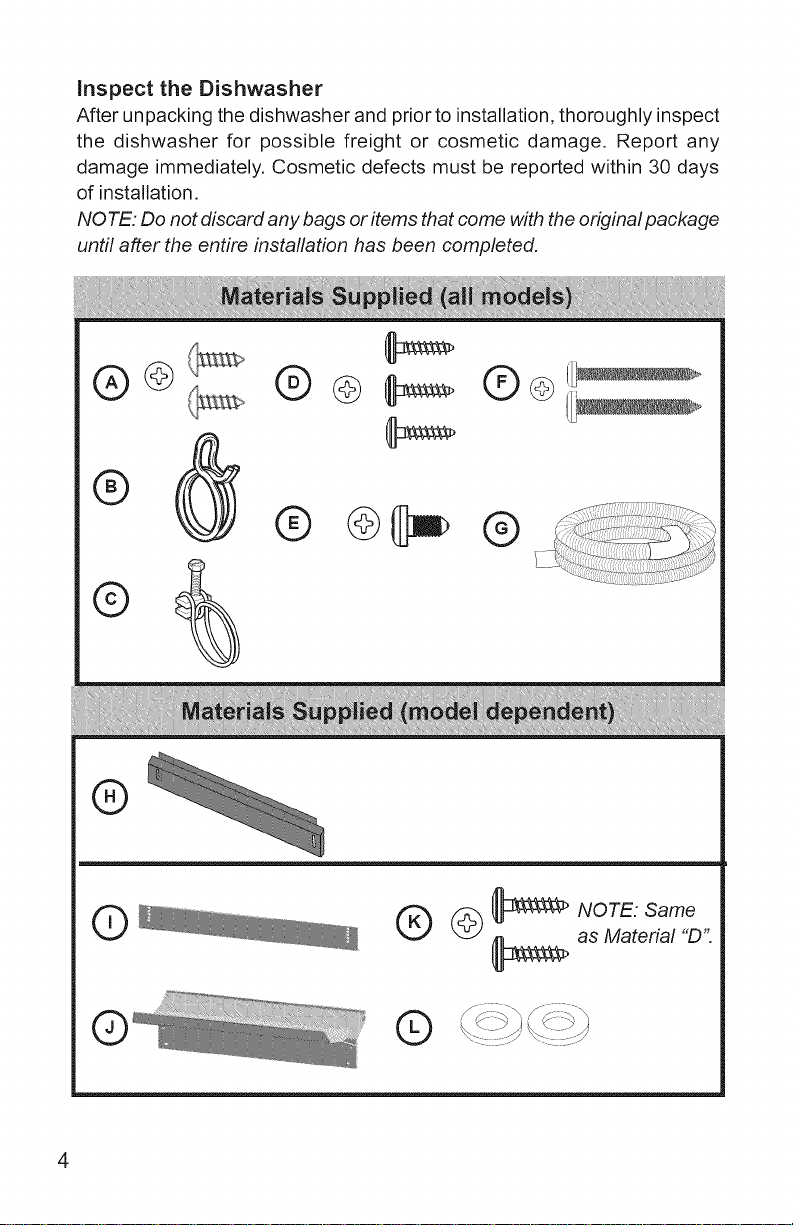
Inspect the Dishwasher
After unpacking the dishwasher and prior to installation, thoroughly inspect
the dishwasher for possible freight or cosmetic damage. Report any
damage immediately. Cosmetic defects must be reported within 30 days
of installation.
NOTE: Do not discard any bags or items that come with the original package
until after the entire installation has been completed.
®@
®@t_@
®
@ _ NOTE: Same
_ as Material "D".
©
E]
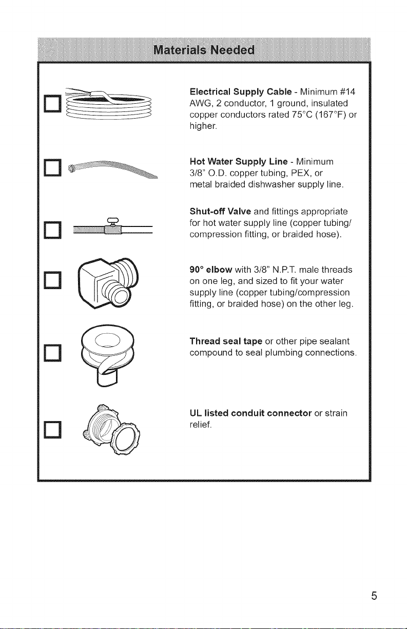
Electrical Supply Cable - Minimum #14
AWG, 2 conductor, 1 ground, insulated
copper conductors rated 75°C (167°F) or
higher.
[3
[3
[3
Hot Water Supply Line - Minimum
3/8" O.D. copper tubing, PEX, or
metal braided dishwasher supply line.
Shut=off Valve and fittings appropriate
for hot water supply line (copper tubing/
compression fitting, or braided hose).
90° elbow with 3/8" N.P.T. male threads
on one leg, and sized to fit your water
supply line (copper tubing/compression
fitting, or braided hose) on the other leg.
Thread seal tape or other pipe sealant
compound to seal plumbing connections.
UL listed conduit connector or strain
relief.
D
D
D
D
D _
D
D I©_
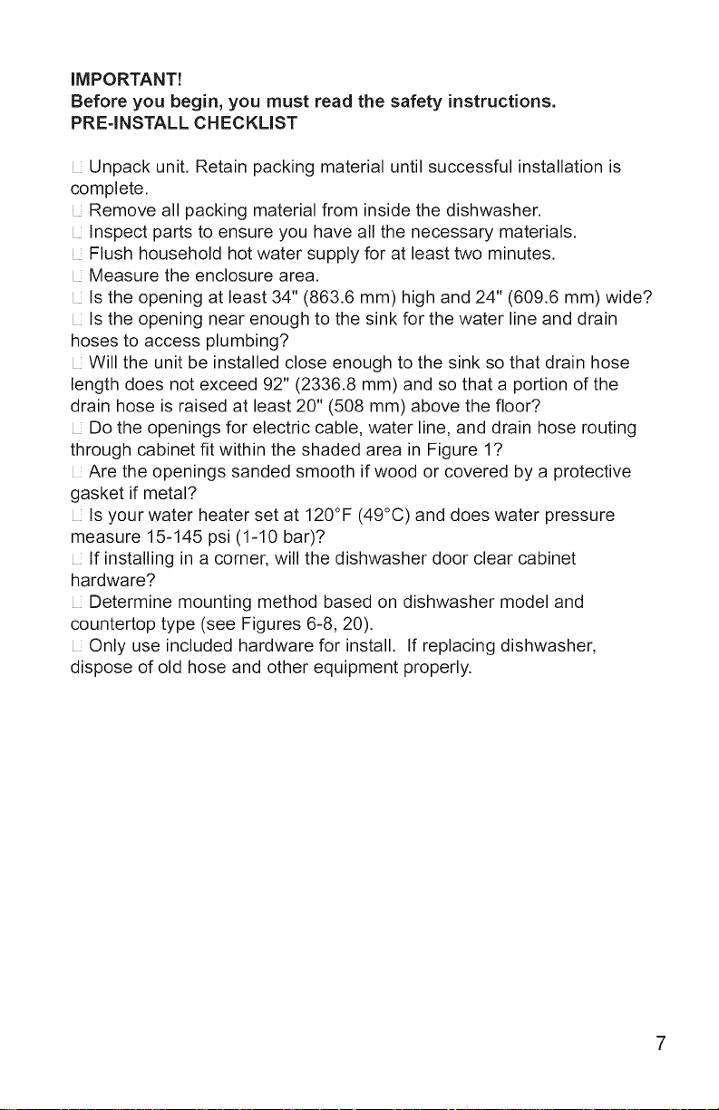
IMPORTANT!
Before you begin, you must read the safety instructions.
PRE=INSTALL CHECKLIST
Unpack unit. Retain packing material until successful installation is
complete.
Remove all packing material from inside the dishwasher.
Inspect parts to ensure you have all the necessary materials.
Flush household hot water supply for at least two minutes.
Measure the enclosure area.
Is the opening at least 34" (863.6 mm) high and 24" (609.6 mm) wide?
Is the opening near enough to the sink for the water line and drain
hoses to access plumbing?
Will the unit be installed close enough to the sink so that drain hose
length does not exceed 92" (2336.8 mm) and so that a portion of the
drain hose is raised at least 20" (508 mm) above the floor?
Do the openings for electric cable, water line, and drain hose routing
through cabinet fit within the shaded area in Figure 1?
Are the openings sanded smooth if wood or covered by a protective
gasket if metal?
Is your water heater set at 120°F (49°C) and does water pressure
measure 15=145 psi (1-10 bar)?
If installing in a corner, will the dishwasher door clear cabinet
hardware?
Determine mounting method based on dishwasher model and
countertop type (see Figures 6-8, 20).
Only use included hardware for install. If replacing dishwasher,
dispose of old hose and other equipment properly.
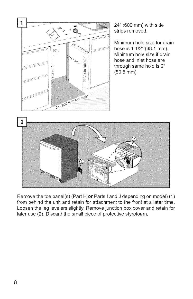
24" (600 mm) with side
strips removed.
Minimum hole size for drain
90 °
hose is 1 1/2" (38.1 mm).
Minimum hole size if drain
hose and inlet hose are
through same hole is 2"
(50.8 mm).
Remove the toe panel(s) (Part H or Parts I and J depending on model) (1)
from behind the unit and retain for attachment to the front at a later time.
Loosen the leg levelers slightly. Remove junction box cover and retain for
later use (2). Discard the small piece of protective styrofoam,
Attach90°elbowjointtodishwasher
orientedasshown,usingthread
sealtapewhenrequired.Donot
over-tighten.
Attachhotwaterlineto90°elbow
androuteunderneathmachine
towardhotwaterconnection.Ensure
thehosedoesnotcontactany
movingpartsbeneaththeunit.
Turnpoweroffatfusebox.Extend
cableapproximately21"(533.4mm)
fromtheopening'sleftside.Extend
thecable30"(762mm)fromthe
backwall.
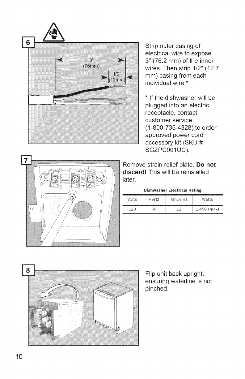
Stripoutercasingof
electricalwiretoexpose
3"(76.2mm)oftheinner
wires.Thenstrip1/2"(12.7
mm)casingfromeach
individualwire.*
*Ifthedishwasherwillbe
pluggedintoanelectric
receptacle,contact
customerservice
(1-800-735-4328)toorder
approvedpowercord
accessorykit(SKU#
SGZPC001UC).
Removestrainreliefplate.Donot
discard!Thiswillbereinstalled
later.
Dishwasher Electrical Rating
Volts Hertz Amperes Watts
120 60 12 1,450 (max)
10
Flip unit back upright,
ensuring waterline is not
pinched.
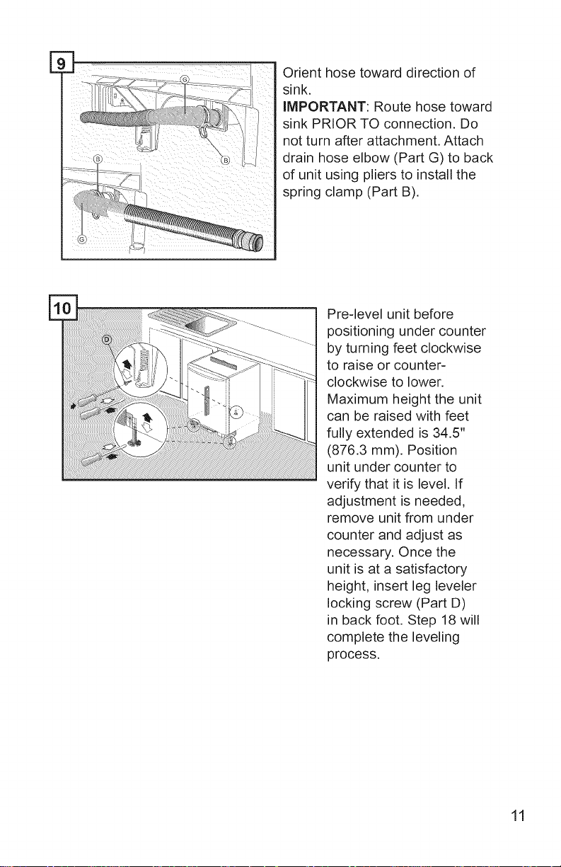
E
Orient hose toward direction of
sink.
IMPORTANT: Route hose toward
sink PRIOR TO connection. Do
not turn after attachment. Attach
drain hose elbow (Part G) to back
of unit using pliers to install the
spring clamp (Part B).
Preqevel unit before
positioning under counter
by turning feet clockwise
to raise or counter-
clockwise to lower.
Maximum height the unit
can be raised with feet
fully extended is 34.5"
(876.3 mm). Position
unit under counter to
verify that it is level. If
adjustment is needed,
remove unit from under
counter and adjust as
necessary. Once the
unit is at a satisfactory
height, insert leg leveler
locking screw (Part D)
in back foot. Step 18 will
complete the leveling
process.
11
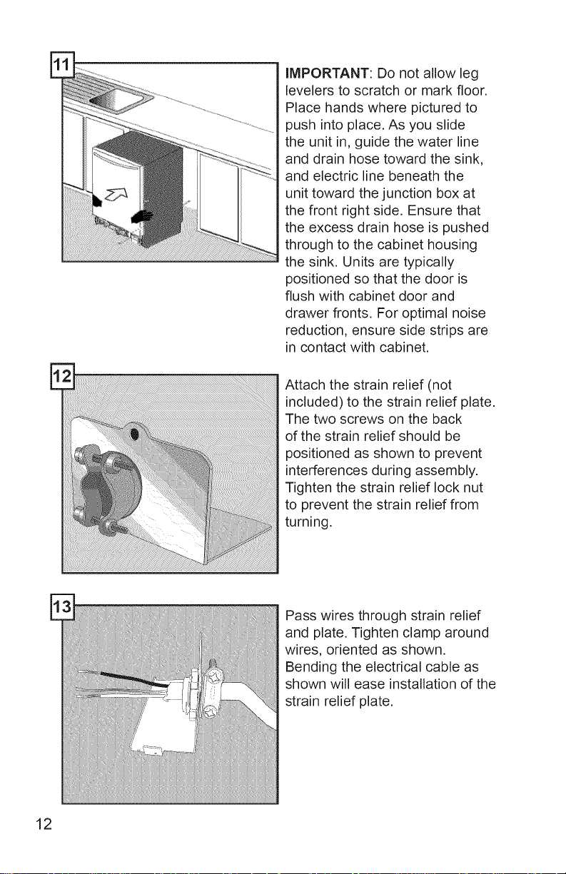
IMPORTANT: Do not allow leg
levelers to scratch or mark floor.
Place hands where pictured to
push into place. As you slide
the unit in, guide the water line
and drain hose toward the sink,
and electric line beneath the
unit toward the junction box at
the front right side. Ensure that
the excess drain hose is pushed
through to the cabinet housing
the sink. Units are typically
positioned so that the door is
flush with cabinet door and
drawer fronts. For optimal noise
reduction, ensure side strips are
in contact with cabinet.
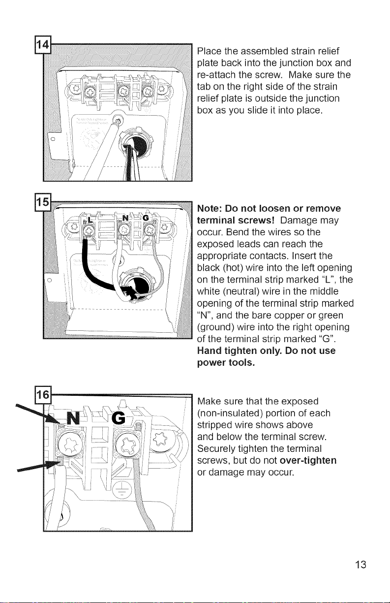
Attach the strain relief (not
included) to the strain relief plate.
The two screws on the back
of the strain relief should be
positioned as shown to prevent
interferences during assembly.
Tighten the strain relief lock nut
to prevent the strain relief from
turning.
12
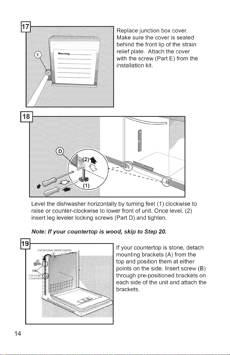
Pass wires through strain relief
and plate. Tighten clamp around
wires, oriented as shown.
Bending the electrical cable as
shown will ease installation of the
strain relief plate.
Place the assembled strain relief
plate back into the junction box and
re-attach the screw. Make sure the
tab on the right side of the strain
relief plate is outside the junction
box as you slide it into place.
E
Note: Do not loosen or remove
terminal screws! Damage may
occur. Bend the wires so the
exposed leads can reach the
appropriate contacts. Insert the
black (hot) wire into the left opening
on the terminal strip marked "L", the
white (neutral) wire in the middle
opening of the terminal strip marked
"N", and the bare copper or green
(ground) wire into the right opening
of the terminal strip marked "G".
Hand tighten only. Do not use
power tools.
Make sure that the exposed
(non-insulated) portion of each
stripped wire shows above
and below the terminal screw.
Securely tighten the terminal
screws, but do not over-tighten
or damage may occur.
13
Replace junction box cover.
Make sure the cover is seated
behind the front lip of the strain
relief plate. Attach the cover
with the screw (Part E) from the
installation kit.
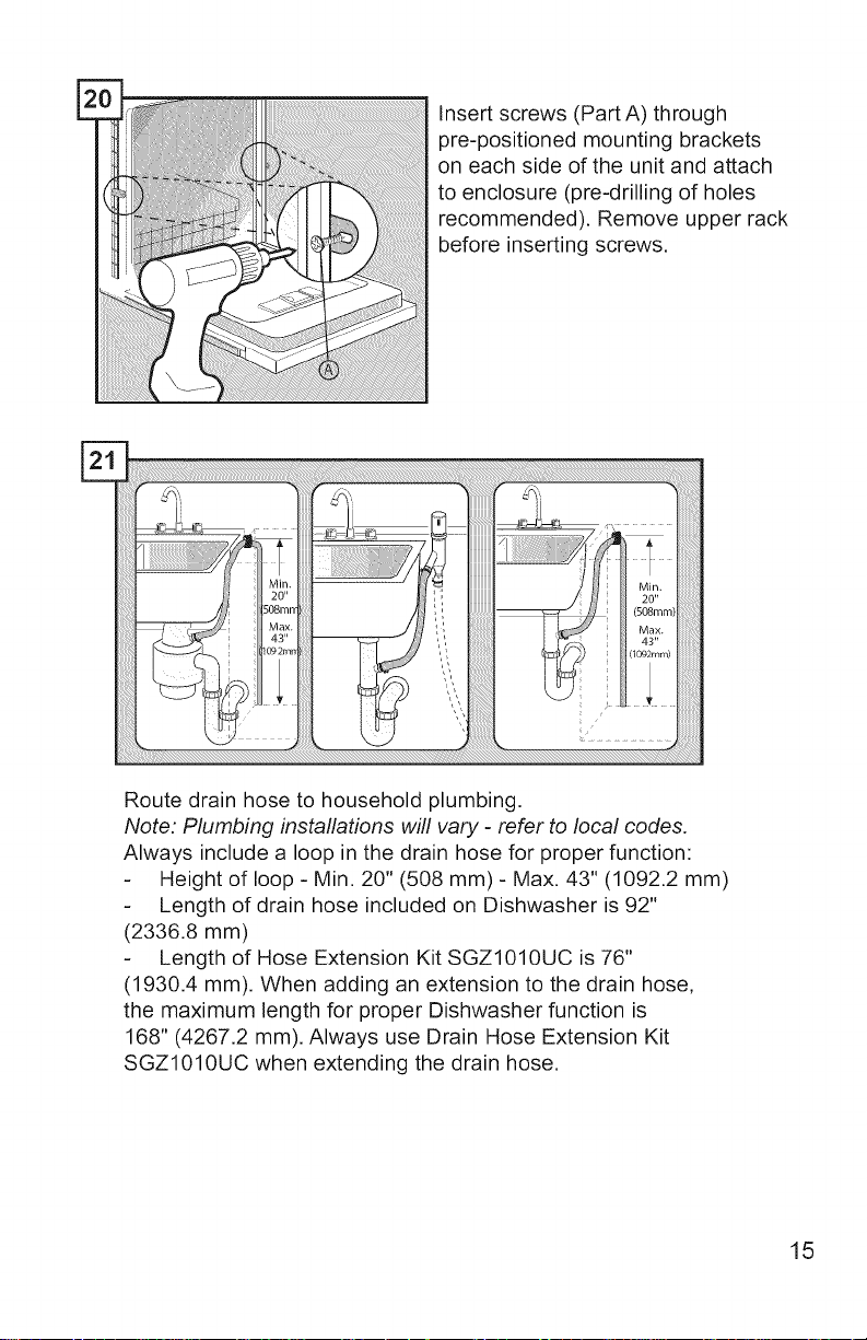
Level the dishwasher horizontally by turning feet (1) clockwise to
raise or counter-clockwise to lower front of unit. Once level, (2)
insert leg leveler locking screws (Part D) and tighten.
Note: If your countertop is wood, skip to Step 20.
E
14
If your countertop is stone, detach
mounting brackets (A) from the
top and position them at either
points on the side. Insert screw (B)
through pre-positioned brackets on
each side of the unit and attach the
brackets.
Insert screws (Part A) through
pre-positioned mounting brackets
on each side of the unit and attach
to enclosure (pre-drilling of holes
recommended). Remove upper rack
before inserting screws.
Route drain hose to household plumbing.
Note: Plumbing installations will vary - refer to local codes.
Always include a loop in the drain hose for proper function:
Height of loop - Min. 20" (508 mm) - Max. 43" (1092.2 mm)
Length of drain hose included on Dishwasher is 92"
(2336.8 mm)
Length of Hose Extension Kit SGZl010UC is 76"
(1930.4 mm). When adding an extension to the drain hose,
the maximum length for proper Dishwasher function is
168" (4267.2 mm). Always use Drain Hose Extension Kit
SGZ1010UC when extending the drain hose.
15
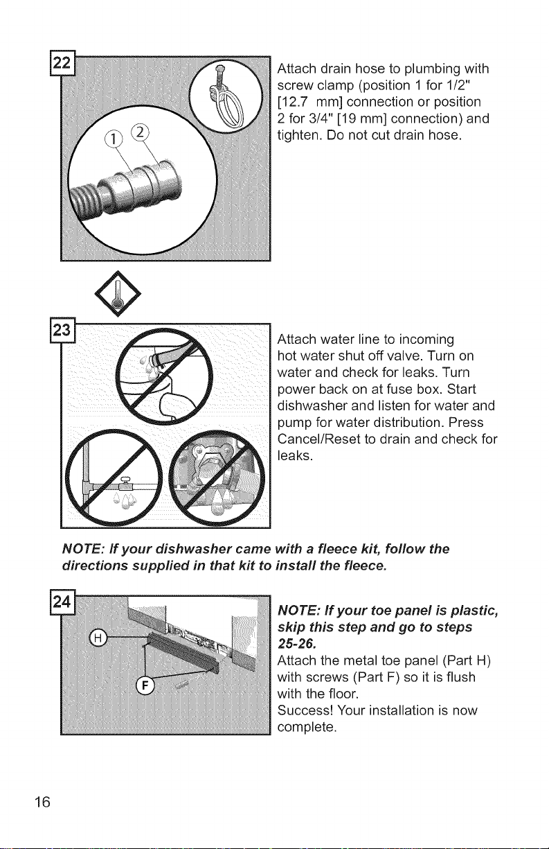
Attach drain hose to plumbing with
screw clamp (position 1 for 1/2"
[12.7 mm] connection or position
2 for 3/4" [19 mm] connection) and
tighten, Do not cut drain hose,
Attach water line to incoming
hot water shut off valve. Turn on
water and check for leaks. Turn
power back on at fuse box. Start
dishwasher and listen for water and
pump for water distribution. Press
Cancel/Reset to drain and check for
leaks,
NOTE: If your dishwasher came with a fleece kit, follow the
directions supplied in that kit to install the fleece.
NOTE: If your toe panel is plastic,
skip this step and go to steps
25-26.
Attach the metal toe panel (Part H)
with screws (Part F) so it is flush
with the floor.
Success! Your installation is now
complete.
16
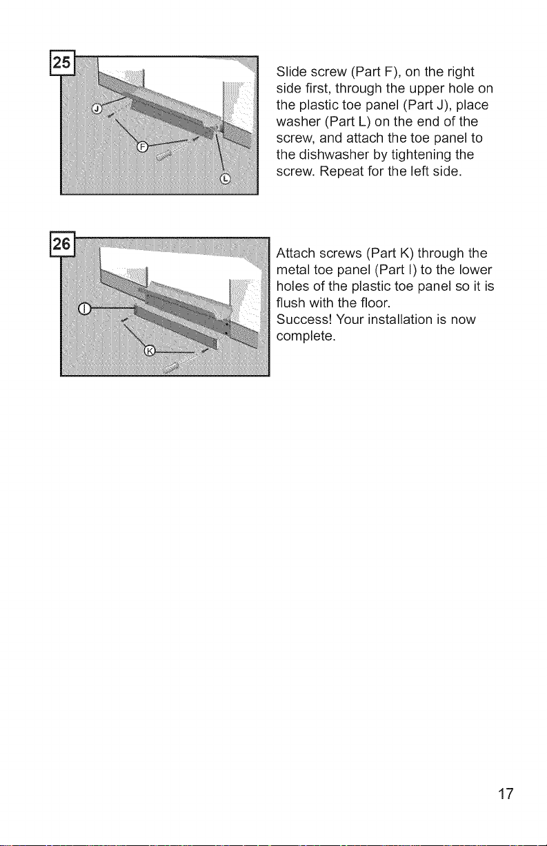
Slide screw (Part F), on the right
side first, through the upper hole on
the plastic toe panel (Part J), place
washer (Part L) on the end of the
screw, and attach the toe panel to
the dishwasher by tightening the
screw. Repeat for the left side.
Attach screws (Part K) through the
metal toe panel (Part I) to the lower
holes of the plastic toe panel so it is
flush with the floor.
Success! Your installation is now
complete.
17
Your dishwasher requires no special care other than that described in the
Care and Maintenance section of the Use and Care Manual. If you are
having a problem with your dishwasher, before calling for service please
refer to the Troubleshooting section in the Use and Care Manual. If service
is necessary, contact your dealer or installer or an authorized service
center.
Do not attempt to repair the appliance yourself. Any work performed
by unauthorized personnel may void the warranty. If you are having a
problem with your dishwasher and are not pleased with the service you
have received, please take the following steps (in the order listed below)
until the problem is corrected to your satisfaction:
1. Contact your installer or the Authorized Service Contractor in your
area.
2. Write us at the address below:
BSH Home Appliances Corporation
1901 Main Street
Irvine, CA 92614
3. Call us at the Customer Service phone number before calling retailer
for technical problems:
1-800-735-4328
Please be sure to include (if you are writing), or have available (if you are
calling), the following information:
• Model number (SH UC)
• Serial number (FD )
• Date of original purchase (mm/dd/yyyy)
• Date the problem originated (mm/dd/yyyy)
• Explanation of the problem
• Daytime phone number where you can be reached.
Please make a copy of your invoice and keep it with this manual. The
customer must show proof of purchase to obtain warranty service.
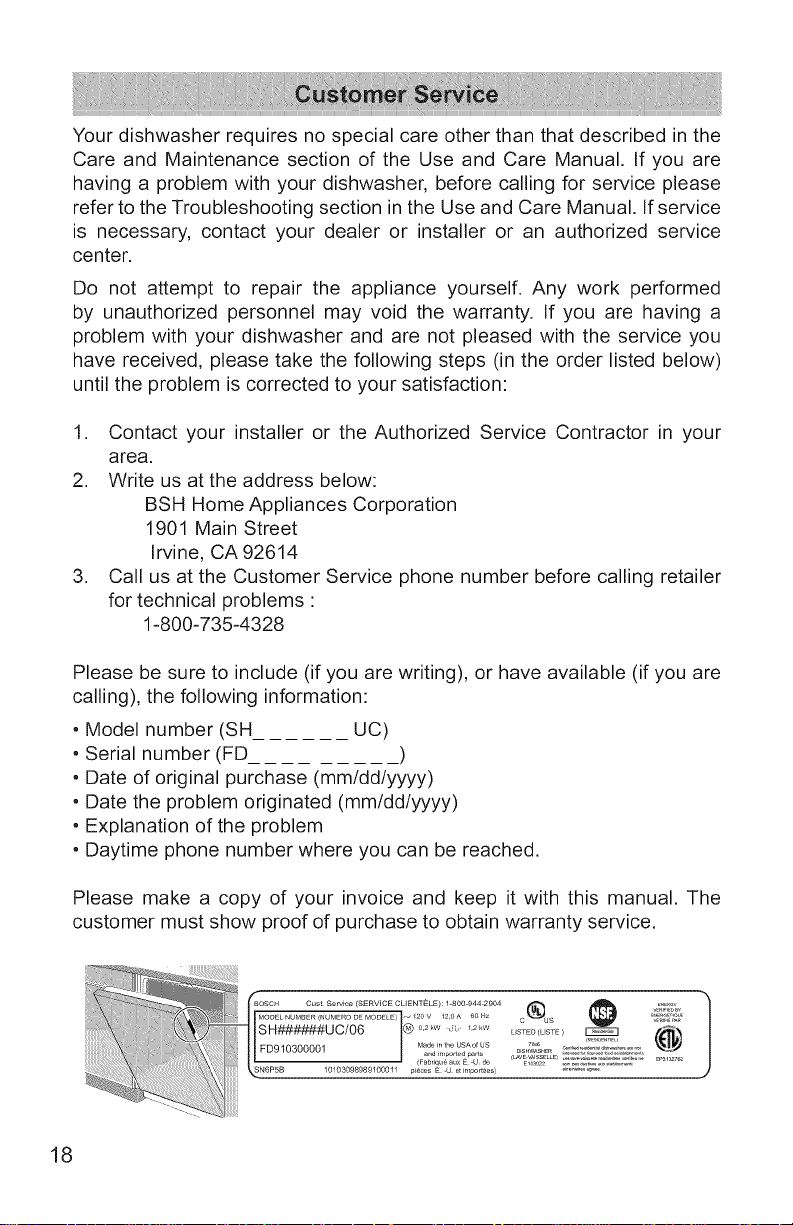
_BOSCH C t S (SERVICE CLIENTELE) 1 8OO 944 29O4 E.Ea¥
--'':}k::2:A--,:!io®US@ ,,:,s,:.<.
SH######U C/06 I@ ...... " L............ )
,i } }:ii1 ,,_ FD910300001 Mad_ in the USA°f US ...... L..............................
i _N6P5B 10103098989100011 pieces E -U et importees) _'_"_'_
18
Instrucciones de seguridad importantes"
Pot favor lea y guarde esta informaci6n
Para evitar posibles lesiones o da_os materiales, RESPETE TODAS LAS
ADVERTENCIAS Y PRECAUCIONES. Estas instrucciones estan dise_adas
para set usadas Onicamente pot instaladores calificados. La lavadora de
platos debe set instalada pot un t6cnico de servicio t6cnico o instalador
calificado.
• Ademas de estas instrucciones, la lavadora de platos debe insta-
larse de conformidad con todos los c6digos y las ordenanzas de
electricidad y de plomeda (nacionales y locales).
Lea estas instrucciones de instalaci6n completamente y sigalas
con cuidado. Le ahorraran tiempo y esfuerzo, y le ayudaran a asegura-
rse de que el rendimiento de la lavadora de platos sea 6ptimo y seguro.
IMPORTANTE
• La manguera de drenaje de la lavadora de platos debe instalarse
manteniendo una parte de esta, al menos, a una distancia de 20" (508
mm) del piso del gabinete; de Io contrario, es posible que la lavadora
de platos no drene correctamente.
• Esta lavadora de platos ha sido dise_ada para uso residencial en inte-
riores Onicamente y no debe usarse en establecimientos comerciales
de servicios de comidas.
Este lavavajillas esta disedado para ser cerrado en la parte superior y
ambos lados pot los gabinetes.
NUEVA INSTALACION: si la lavadora de platos es una instalaci6n
nueva, la mayoria del trabajo debe realizarse antes de que la lavadora
de platos sea colocada en su lugar.
REEMPLAZO: si la lavadora de platos reemplaza a otra lavadora de
platos, verifique las conexiones de la lavadora de platos existente para
ver la comp,atibilidad con la nueva lavadora de platos y reemplace las
piezas segun sea necesario.
• Este electrodom6stico cumple con la norma CAN/CSA-C22.2 n.° 167/
UL 749. Es responsabilidad del propietario y del instalador determinar
si se aplican otros requisitos y normas en instalaciones especificas.
• Esta unidad no esta destinada para uso en exteriores.
Cdmoevitarpeligros generales
Use la lavadora de platos _nicamente cuando est6 completamente
instalada. AI abrir la puerta de una lavadora de platos que no esta
instalada, abra la puerta con cuidado mientras sostiene la parte posterior
de la unidad. No seguir esta advertencia puede provocar que la lavadora
de platos se caiga, Io que ocasiona lesiones graves.
Antes de instalar los soportes de montaje en "L" para la encimera sumi-
nistrados con la unidad (solo en algunos modelos), decida qu6 m6todo
se usara para asegurar la lavadora de platos en su abertura. Una vez
que estos soportes de montaje est_n instalados en la lavadora de platos,
es dificil retirarlos, y esto dafia los soportes de montaje y la lavadora de
platos.
En algunas condiciones, se puede formar gas hidr6geno en un sistema
de agua caliente que no se ha utilizado durante semanas. El gas hi-
dr6geno es explosivo.
Antes de Ilenar una lavadora de platos con un sistema que ha estado
apagado durante semanas, deje correr agua de un grifo cercano en un
_rea bien ventilada hasta que no haya sonido ni evidencia de gas.
Las temperaturas requeridas para soldar y fundir dafian la base y la
valvula de entrada de agua de la lavadora de platos. Si se van a soldar o
fundir las tuberias para plomeria, mantenga la fuente de calor, al menos,
a 6" (152.4 mm) de distancia de la base y de la valvula de entrada de
agua de la lavadora de platos.
Retirar cualquier cubierta o jalar la lavadora de platos del gabinete
puede hacer que queden expuestas las conexiones de agua caliente, la
alimentaci6n el6ctrica, y puntas o bordes filosos. Manipule la unidad con
cuidado.
C6mo evitar peligros de descarga el_ctrica/incendio '_
No permita que las lineas de electricidad ni las tuberias de suministro de
agua entren en contacto. Se suministran canales separados debajo de la
lavadora de platos.
No trabaje en un circuito energizado. Hacerlo podria ocasionar lesio-
nes graves o la muerte. 0nicamente los electricistas calificados pueden
realizar la instalaci6n el6ctrica. No intente realizar ningOn trabajo en el
circuito de suministro el6ctrico de la lavadora de platos hasta que est6
seguro de que el circuito se encuentra desenergizado.
Aseg0resedequelainstalaci6nel6ctricasehayarealizadocorrecta-
mente.Nodebehaberconexionesel6ctricassueltas.Aseg0resedeque
todaslasconexionesel6ctricassehayanrealizadocorrectamente.
Elclientetienelaresponsabilidaddeasegurarsedequelainstalaci6n
el6ctricadelalavadoradeplatoscumplacontodoslosc6digosylasor-
denanzasdeelectricidadnacionalesylocales.Lalavadoradeplatosesta
dise_adaparaunsuministroel6ctricodeCAde120V,60Hz,conectadoa
uncircuitoel6ctricoconunaconexi6natierraadecuada,exclusivoparala
lavadoradeplatos,conunfusibleodisyuntorconcapacidadnominalpara
15A.Losconductoresdelsuministroel6ctricodebensetdealambre,Oni-
camentedecobre,conuncalibredealambreestadounidense(American
WireGauge,AWG)n.°14comominimo,concapacidadnominalparauso
entemperaturasde75°C(167°F)omasaltas.
Esteelectrodom6sticodebeconectarseaunsistemadecableadometalico
y permanente,conconexi6natierra,o debeinstalarseunconductorde
conexi6na tierraparaequiposjuntoconlosconductoresde circuitos
y conectarloalterminalde conexi6natierraparaequiposo al hilode
conexi6natierradelelectrodom6stico.Nousecablesdeextensi6n.
C6moevitarpeligrosenlastuberiasy peligros A
deescaldadura
NorealiceningOntrabajoenunatuber[adeaguacalientequetengacarga.
Podriaocasionarlesionesgraves.0nicamentelosplomeroscalificados
puedenrealizartrabajosdeplomer[a.NointenterealizarningOntipodetrabajo
enlastuber[asdesuministrodeaguacalientedelalavadoradeplatoshasta
queest6segurodequeelsuministrodeaguacalienteestacerrado.
Noaprieteenexcesoelcodode90°.Hacerlopuededa_arlavalvulade
entradadeaguay provocarunap6rdidadeagua.
Lastemperaturasrequeridasparasoldary fundirda_anla valvulade
entradadeaguadelalavadoradeplatos.Sisevanasoldarofundirlas
tuberiasparaplomeria,mantengalafuentedecalor,almenos,a6"(152.4
mm)dedistanciadelav_lvuladeentradadeaguadelalavadoradeplatos.
Consultelosc6digosdeplomerialocalesparaconocerlosprocedimientos
y losaccesoriosdeplomeriaaprobados.Todoslostrabajosdeplomer[a
debenrealizarsesegQnlosc6digosnacionalesylocales.
Estasinstruccionesdescribenunm6tododeinstalaci6nparamangueras
trenzadasdeaceroinoxidableo tuberiasdesuministrodeaguacaliente
depolietilenoreticulado(Cross-linkedpolyethylene,PEX).Siusatubosde
cobreo deotromaterialparaelsuministrodeagua,hagaqueunplomero
autorizadorealicelainstalaci6ncorrespondiente.
3
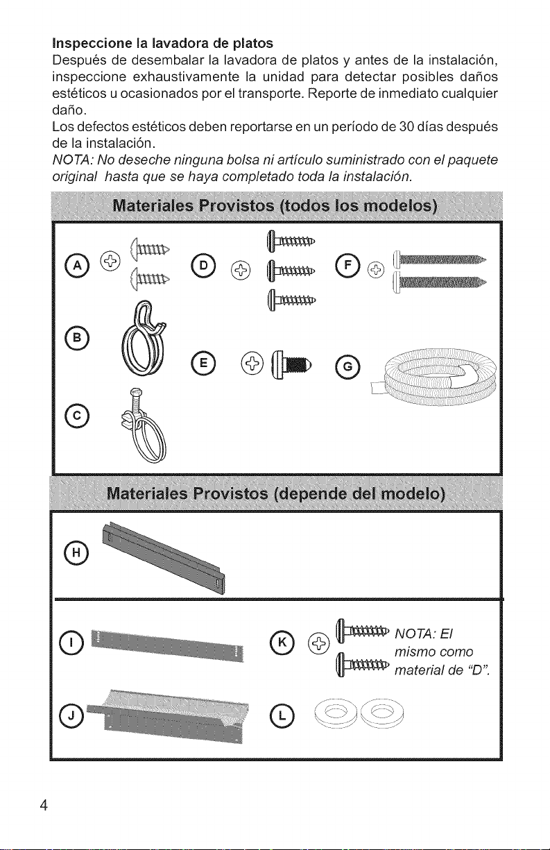
Inspeccione la lavadora de platos
Despu6s de desembalar la lavadora de platos y antes de la instalaci6n,
inspeccione e×haustivamente la unidad para detectar posibles dafios
est6ticos u ocasionados por el transporte. Reporte de inmediato cualquier
dafio.
Los defectos est6ticos deben reportarse en un periodo de 30 d[as despu6s
de la instalaci6n.
NOTA: No deseche ninguna bolsa ni articulo suministrado con el paquete
original hasta que se haya completado toda la instalaci6n.
®@
® @l]_ @
®
Q_
®
©
_ mlsmo como
material de "D".
 Loading...