

Page 1
SE485
Installation Instructions
EN
Interface
Page 2
SE485 | Installation Instructions |
SE485
Transponder
RX- TXRX+ TX+
TX- RXTX+ RX+
TX+
GND
+9V
1
1.0 Introduction
EN | 2
1.0 Introduction
The SE485 is designed as an interface between the
RS-485 signal bus of the Security Escort Transponder
and the Serial Bus (RS-232) of the Security Escort
Central Station.
2.0 Specifications
Table 1: Specifications
Dimensions
Power
Recommended
Cable
Compatibility
135 mm x 85 mm x 30 mm
( 5.375 in. x 3.3125 in. x 1.1875 in.)
Use the included 120 VAC adapter to
9 VDC, 300 mA or power from the
transponder.
Two twisted pair, four conductor,
0.8 mm (22 AWG)
EA500B Transponder
EA501B Transponder
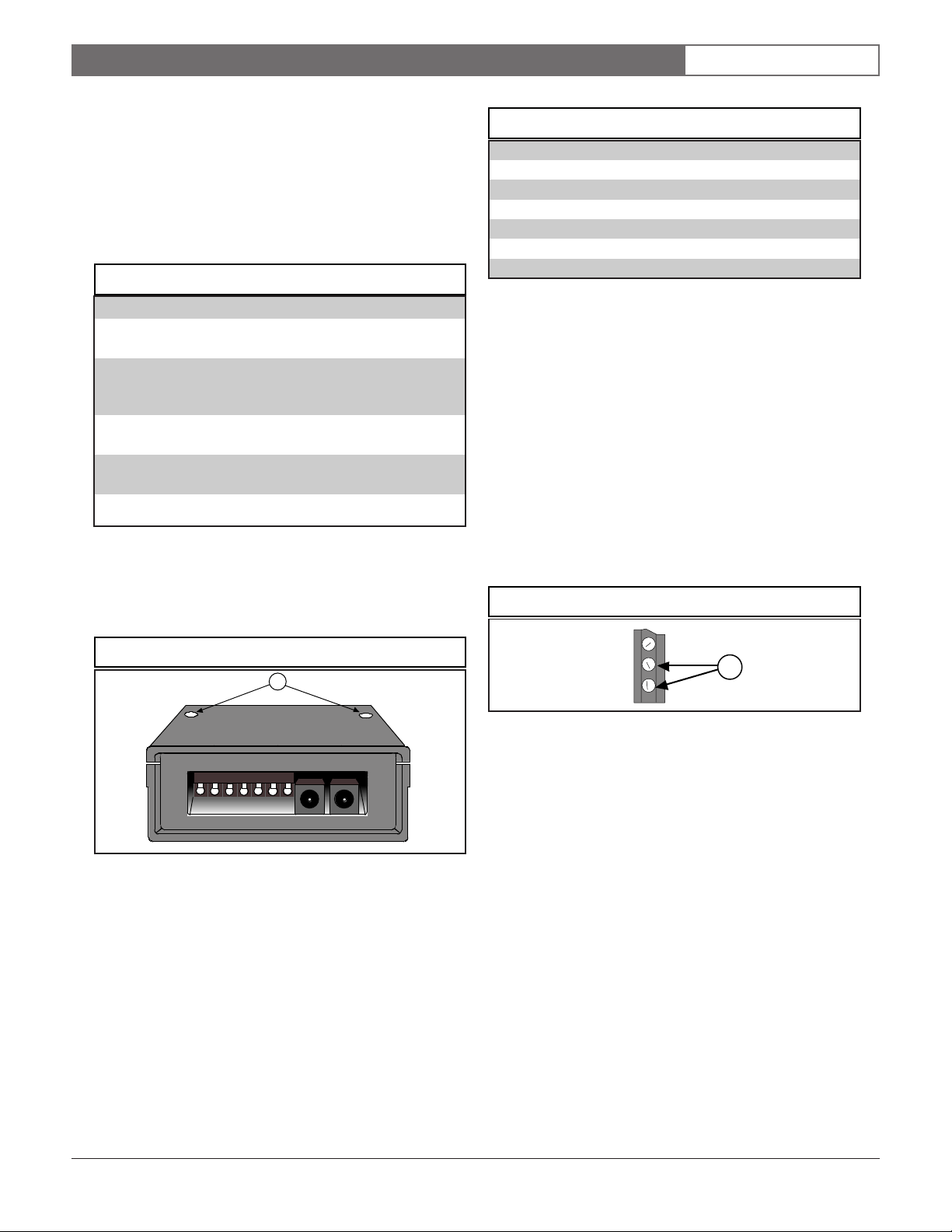
3.0 Installation
To install the SE485:
1. Remove the cover by removing the cover screws
(see Figure 1).
Figure 1: SE485 Enclosure
Table 2: Wiring Chart
4.0 Installation and Operation
Notes
• Each transponder must have its own address.
• For the Security Escort system to maintain operation,
the SE485 must be powered at all times. Use the 9 V
adaptor provided plugged into an Uninterrupted
Power Supply (UPS).
• The SE485 can also be powered from the
transponder’s 9 V output connected to the
9 VDC input wiring connectors (see Figure 3).
• Up to four SE485s can be included in an installation.
For multiple SE485s, use the connector cable
provided.
Figure 3: Transponder Power
1 - Cover screws
2. Connect the wiring (see Figure 2).
3. After wiring the system, replace the cover and
4. Wire the connectors as indicated in Table 2.
Bosch Security Systems | 06/03| 30885D
1
1 - 9 VDC input from transponder
power up the unit.
Page 3

SE485 | Installation Instructions |
Figure 2: Wiring Diagram
4.0 Installation and Operation Notes
7
8
EN | 3
1
2
-
+
RX-
RX+
GND
TX-
TX+
GND
+9V
9
3
6
TXTX+
GND
RXRX+
5
TXTX+
GND
RXRX+
4
1 - Twisted pair wire 6 - Power LED
2 - Power supply (31578) center positive 7 - Optional 9 VDC input from transponder
3 - Connector for multiple SE485s 8 - Wiring connectors to transponder (ground not needed)
4 - To next transponder 9 - To central station RS-232 port. Use 25 pin male to 9
5 - Escort transponder pin female (or 25 pin male to 25 pin female) straight
computer serial cable no longer than 15 m (50 feet).
Do not use null modem cable.
Bosch Security Systems | 6/03 | 30885D
Page 4

Bosch Security Systems
130 Perinton Parkway
Fairport, NY 14450-9199 USA
www.boschsecurity.us
Customer Service: (800) 289-0096
Technical Support: (888) 886-6189
© 2003 Bosch Security Systems
Subject to change | Printed in the USA
30885D
 Loading...