

Bosch SCT 815, SCT 815 S1, SCT 815 S2 Original Instructions Manual
SCT 815
Adjustment device
de
Originalbetriebsanleitung
en
Original instructions
bg
Оригинална инструкция
cs
Původní návod k používání
da
Original brugsanvisning
el
Πρωτότυπο εγχειρίδιο
es
Manual original
et
Originaalkasutusjuhend
fi
Alkuperäiset ohjeet
fr
Notice originale
hr
Originalne upute za rad
hu
Eredeti használati utasitás
it
Istruzioni originali
ja
取扱説明書の原本
lt
Originali eksploatacijos instrukcija
lv
Oriģinālā ekspluatācijas instrukcija
nl
Oorspronkelijke gebruiksaanwijzing
no
Original driftsinstruks
pl
Oryginalna instrukcja
pt
Manual original
ro
Instrucţiuni originale
ru
Оригинальное руководство по эксплуатации
sk
Originál prevádzkového návod
sl
Prevod originalnih navodil za obratovanje
sv
Bruksanvisning i original
tr
Orijinal işletme talimatı
zh
原始的指南
Kalibriervorrichtung
Adjustment device
Устройство за калибриране
Seřizovací zařízení
Kalibreringsanordning
Διάταξη καλιμπραρίσματος
Dispositivo de calibración
Kalibreerimisseadis
Kalibrointilaite
Dispositif d'ajustage
Naprava za kalibriranje
Kalibráló berendezés
Dispositivo di calibrazione
キキャリブレーションデバイス
Kalibravimo įtaisas
Kalibrēšanas ierīce
Kalibreertoestel
Kalibreringsinnretning
Urządzenie kalibrujące
Calibrador
Dispozitiv de calibrare
Калибровочное приспособление
Kalibračný prípravok
Orodje za kalibriranje
Justeringsdon
Kalibrasyon teçhizatı
校准装置
de | 2 | SCT 815
1 Benutzerhinweise... ....................................... 2
1.1 Symbole in der Dokumentation... ................... 2
1.2 Warnhinweise in der Dokumentation... ........... 2
1.3 Zielgruppe... ................................................... 2
1.4 Gewährleistung und Haftung... ....................... 2
1.5 Sicherheitshinweise... ..................................... 3
1.6 Mitgeltende Unterlagen... ............................... 3
2 Produktbeschreibung... ................................. 3
2.1 Bestimmungsgemäße Verwendung... .............. 3
2.2 Produktvarianten... ......................................... 3
2.3 Lieferumfang... ................................................ 3
2.4 Übersicht SCT 815... ....................................... 4
2.5 Voraussetzungen... .......................................... 4
2.6 Laser-Entfernungsmesser GLM 20... ............... 4
2.7 Funktionsbeschreibung... ............................... 4
3 Erstinbetriebnahme
... ....................................
5
3.1 SCT 815 montieren... ...................................... 5
4 Bedienung
... ...................................................
6
4.1 SCT 815 für die Radarsensor-Kalibrierung
positionieren... ............................................... 6
4.2 Linienlaser an SCT 815 befestigen... .............. 6
4.3 Entfernung von SCT 815 zum Fahrzeug
einstellen... ..................................................... 7
4.4 SCT 815 zur Fahrzeug-Längsmittelebene
ausrichten... .................................................... 8
4.5 Höhe des Tripelspiegels einstellen... .............. 9
4.6 Offset (bis 25 cm) zur Fahrzeug-
Längsmittelebene einstellen... ...................... 10
4.7 Offset (ab 25 cm) zur Fahrzeug-
Längsmittelebene einstellen... ...................... 10
5 Instandhaltung... .......................................... 11
5.1 Reinigung... ................................................... 11
5.2 Ersatzteile... .................................................. 11
5.3 Stellfuß wechseln... ...................................... 11
6 Außerbetriebnahme... .................................. 11
6.1 Ortswechsel... .............................................. 11
6.2 Entsorgung und Verschrottung... .................. 11
7 Technische Daten... ..................................... 11
7.1 Maße und Gewicht... ..................................... 11
1. Benutzerhinweise
1.1 Symbole in der Dokumentation
Warnt vor möglichen Sachschäden am Prüfling, am
Produkt oder vor Umweltschäden.
Anwendungshinweise, Empfehlung oder Verweis
Warnt vor einer möglichen Gefahr für den Anwender in
nachfolgenden Handlungsaufforderungen
Einschrittige Handlungsaufforderung
Optionaler Handlungsschritt
Resultat einer Handlungsaufforderung
Verweis auf eine Abbildung. Beispiel: 12(2) bedeutet
Abbildung 12, Position 2
Verweis auf eine Seite.
1.2 Warnhinweise in der Dokumentation
Warnhinweise warnen vor Gefahren für den Benutzer
oder umstehende Personen. Zusätzlich beschreiben
Warnhinweise die Art, Quelle und Folgen der Gefahr
sowie die Maßnahmen zur Vermeidung.
Warnhinweise haben folgenden Aufbau:
Signalwort
Warnsymbol
Das Signalwort zeigt die Eintrittswahrscheinlichkeit
sowie die Schwere der Gefahr bei Missachtung:
Signalwort Eintrittswahrscheinlichkeit Schwere der
GEFAHR Unmittelbar drohende
WARNUNG Mögliche drohende Gefahr Tod oder schwere
VORSICHT Mögliche gefährliche
1.3 Zielgruppe
Das Produkt darf nur von ausgebildetem und
eingewiesenem Personal benutzt werden. Zu
schulendes, anzulernendes, einzuweisendes oder im
Rahmen einer allgemeinen Ausbildung befindliches
Personal darf nur unter ständiger Aufsicht einer
erfahrenen Person an dem Produkt tätig werden.
Kinder müssen beaufsichtigt werden, um
sicherzustellen, dass sie nicht mit dem Produkt
spielen.
---Separator---
Art, Quelle und Folgen der Gefahr.
Maßnahmen und Hinweise zur
Vermeidung der Gefahr.
Gefahr bei
Missachtung
Gefahr
Situation
Tod oder schwere
Körperverletzung
Körperverletzung
Leichte
Körperverletzung
1.4 Gewährleistung und Haftung
Es dürfen keine Veränderungen an unseren Produkten
vorgenommen werden. Unsere Produkte dürfen nur mit
Originalzubehör und Originalersatzteilen verwendet
werden. Andernfalls entfallen sämtliche
Gewährleistungsansprüche.
---Separator---
1 689 989 362 | 2018-08-01 Robert Bosch GmbH
Produktbeschreibung | SCT 815 | 3 | de
1.5 Sicherheitshinweise
WARNUNG
Schwere Augenschäden durch Laserstrahl. Tod
oder schwere Körperverletzung.
Niemals direkt in die Laserquelle sehen.
Laserstrahl niemals auf Personen,
insbesondere auf Gesicht und Augen, richten.
Zur Funktionskontrolle einen Gegenstand vor
den Austrittspunkt des Laser-
---Separator---
Entfernungsmessers und Linienlasers halten.
VORSICHT
Verletzungsgefahr durch herunterfallende
Gegenstände von SCT 815. Leichte
Körperverletzung.
Sicherheitsschuhe tragen.
Linienlaser immer mit dem Fangseil sichern.
---Separator---
VORSICHT
Quetschgefahr beim Einstellen der Höhe des
Tripelspiegels. Leichte Körperverletzung.
Während der Höheneinstellung des
Tripelspiegels keine Finger zwischen
---Separator---
Klemmhalter und Führungsrohre bringen.
1.6 Mitgeltende Unterlagen
1 690 386 038 - Originalbetriebsanleitung P-Assist S5
•
1 689 989 376 - Originalbetriebsanleitung GLM 20
•
1 689 989 363 - Kurzanleitung Honda
•
1 689 989 364 - Kurzanleitung Toyota
•
1 689 989 365 - Kurzanleitung Mazda
•
1 689 989 366 - Kurzanleitung Kia
•
1 689 989 367 - Kurzanleitung Hyundai
•
---Separator---
2. Produktbeschreibung
2.1 Bestimmungsgemäße Verwendung
SCT 815, SCT 815 S1 und SCT 815 S2 sind
Kalibriervorrichtungen zur Kalibrierung des
Frontradarsensors folgender Fahrzeughersteller:
Mazda
•
Honda
•
Toyota
•
KIA
•
• Hyundai
In Verbindung mit einer Diagnose-Software kann der
Frontradarsensor für ACC (Adaptive Cruise Control)
und für den Notbremsassistenten kalibriert werden.
Ausstattungsvariante Linienlaser P-
Assist S5
SCT 815 – –
SCT 815 S1 – •
SCT 815 S2 • •
– nicht im Lieferumfang enthalten
• im Lieferumfang enthalten
LaserEntfernungsmesser
GLM 20
Die Produktvarianten werden nachstehend vereinfacht
als SCT 815 bezeichnet.
---Separator---
2.3 Lieferumfang
Benennung Teilenummer
Grundplatte 1 688 000 368
Führungsrohre 1 680 700 313
Aufnahme für Linienlaser 1 681 038 414
Klemmhalter für Tripelspiegel 1 688 040 319
3 Kunststoffschrauben 1 683 414 021
Tripelspiegel 1 685 350 017
Aufnahme für Laser-Entfernungsmesser 1 680 423 011
Laser-Entfernungsmesser GLM 20* 1 687 010 600
Linienlaser P-Assist S5* 1 690 381 124
Originalbetriebsanleitung 1 689 989 362
Kurzanleitung Honda 1 689 989 363
Kurzanleitung Toyota 1 689 989 364
Kurzanleitung Mazda 1 689 989 365
Kurzanleitung Kia 1 689 989 366
Kurzanleitung Hyundai 1 689 989 367
8 Innensechskantschrauben, 16
Unterlegscheiben, 8 Senkschrauben, 8
Sechskantmuttern
---Separator---
* abhängig von der Produktvariante
---Separator---
1 687 010 613
Jede darüber hinausgehende Verwendung gilt
als nicht bestimmungsgemäß und ist nicht
zulässig.
---Separator---
2.2 Produktvarianten
SCT 815 gibt es in drei Ausstattungsvarianten. Die
Ausstattungsvarianten unterscheiden sich durch den
Lieferumfang. Entsprechend der Ausstattungsvariante
sind 0, 1 oder 2 Laser enthalten.
1 689 989 362 | 2018-08-01Robert Bosch GmbH
1
2
3
3
4
5
6
7
8
5 – 10 m
4 – 5 m
1
2
de | 4 | SCT 815 | Produktbeschreibung
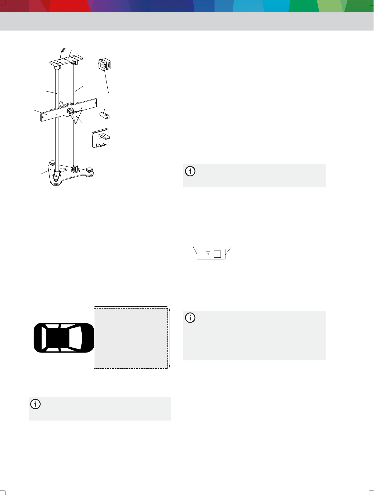
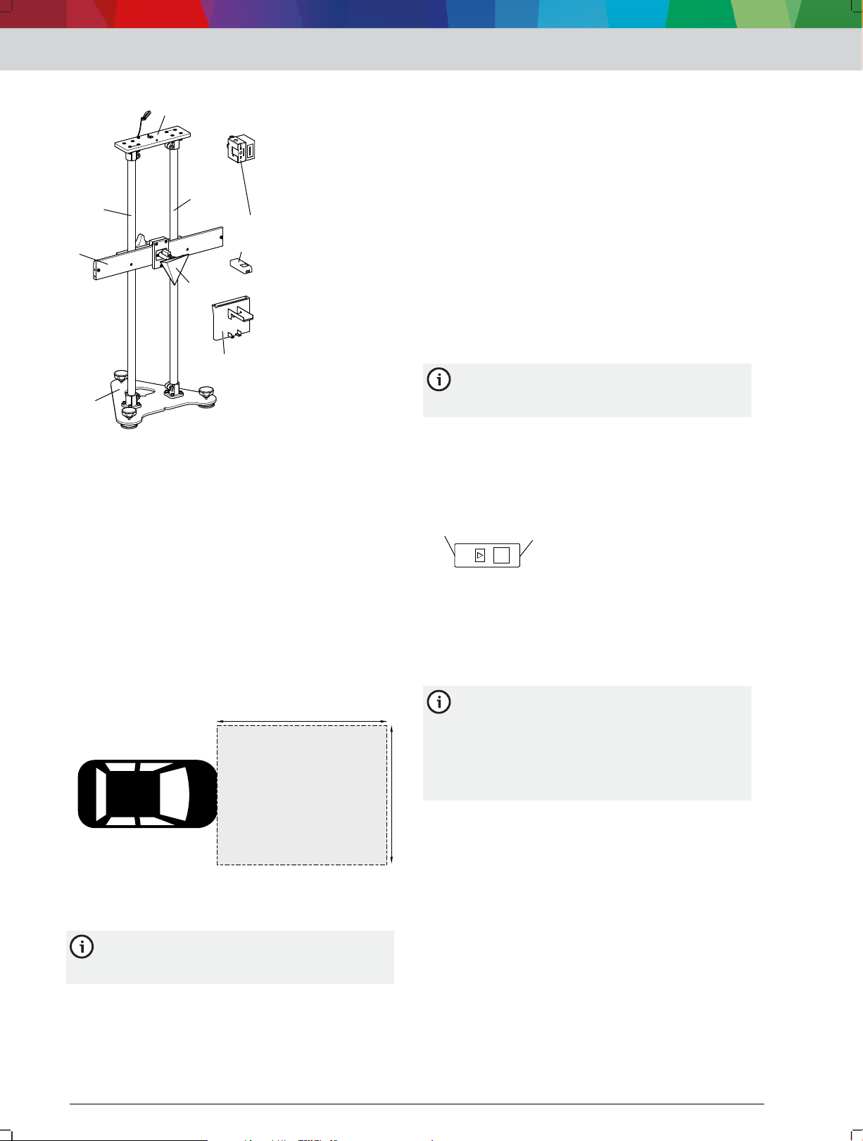
2.4 Übersicht SCT 815
1: SCT 815
(1) Grundplatte
(2) Klemmhalter für Tripelspiegel
(3) Führungsrohre
(4) Aufnahme für Linienlaser
(5) Linienlaser P-Assist S5
(6) Laser-Entfernungsmesser GLM 20
(7) Tripelspiegel
(8) Aufnahme für Laser-Entfernungsmesser
---Separator---
Diagnose-Software
• Diagnose-Software, um den Frontradarsensor
kalibrieren zu können
• Falls [ESI]tronic 2.0 als Diagnose-Software
verwendet wird: Informationsart SD (SteuergeräteDiagnose) sowie ein KTS
---Separator---
2.6 Laser-Entfernungsmesser GLM 20
Mithilfe des Laser-Entfernungsmessers GLM 20 wird
SCT 815 vor dem Fahrzeug positioniert und die Höhe
des Tripelspiegels eingestellt.
Der Laser-Entfernungsmesser GLM 20 verfügt über
folgende Eigenschaften, um SCT 815 exakt nach den
Angaben in den fahrzeugspezifischen Kurzanleitungen
positionieren zu können:
•
Kontinuierliche Entfernungsmessung
Hintere Kante als Bezugspunkt für die
•
Entfernungsmessung
Für die Ausstattungsvariante SCT 815 (ohne
Laser im Lieferumfang) empfehlen wir den GLM
20 als Laser-Entfernungsmesser.
Alle Eigenschaften und Funktionen von GLM 20 sind in
der Originalbetriebsanleitung 1 689 989 376
beschrieben.Falls ein anderer Laser-Entfernungsmesser
als GLM 20 verwendet wird, müssen folgende
Eigenschaften erfüllt sein:
Hintere Kante als Bezugspunkt für die
•
Entfernungsmessung
2.5 Voraussetzungen
Messplatz
Maximale Unebenheit am Messplatz: 1 mm
•
Maximale Unebenheit an der Aufstellfläche des
•
Fahrzeugs: 10 mm
Benötigte Freifläche vor der Fahrzeugfront: 5 - 10 m
•
Länge / 4 - 5 m Breite
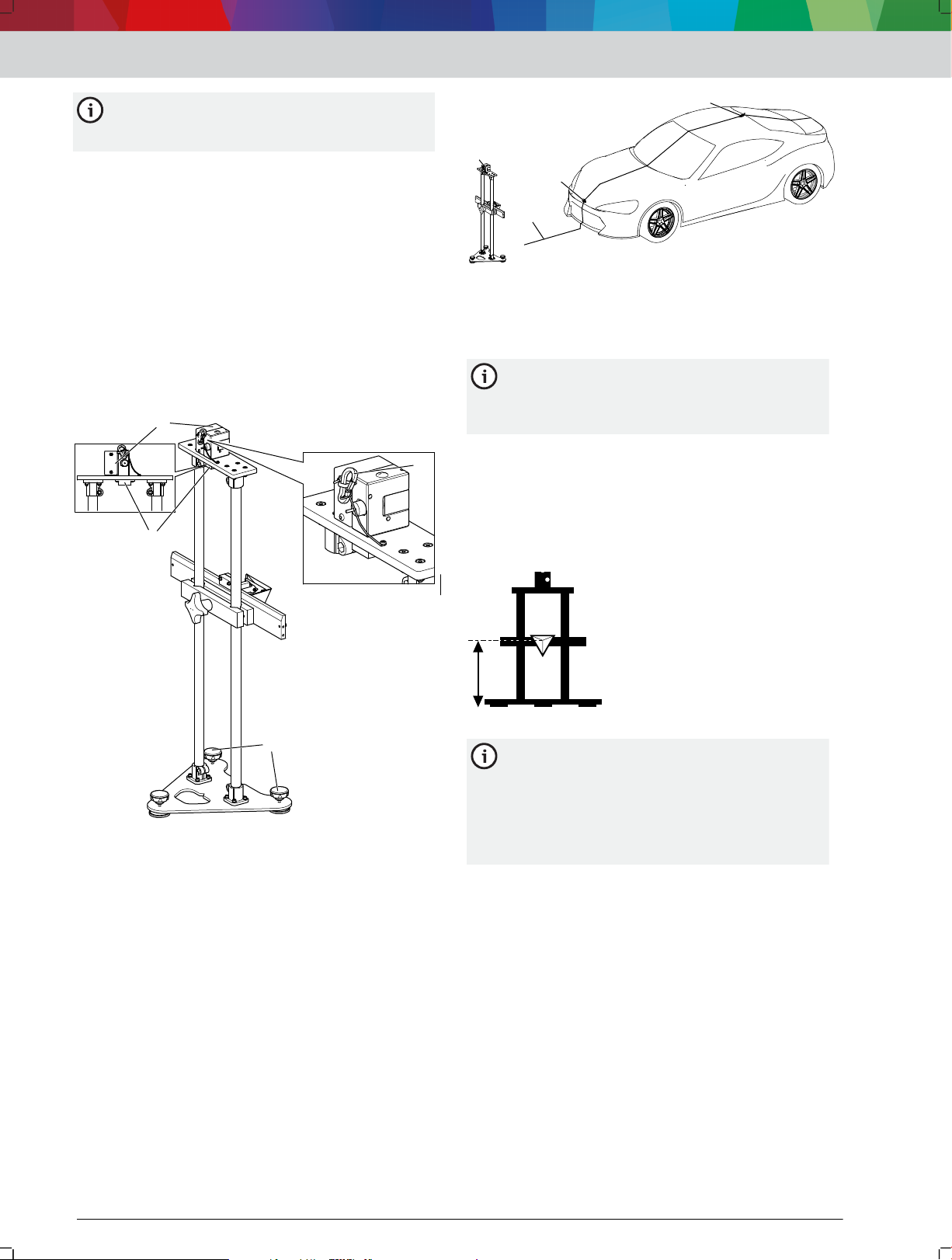
2: Freifläche vor dem Fahrzeug
• Die Freifläche vor der Fahrzeugfront muss frei von
metallischen Gegenständen sein.
---Separator---
Innerhalb der Freifläche vor dem Fahrzeug wird
SCT 815 positioniert. Metallische Gegenstände
stören die Kalibrierung des Frontradarsensors.
3: Bezugspunkt für Entfernungsmessung
(1) Hintere Kante als Bezugspunkt für die Entfernungsmessung
(2) Laseraustritt
Exakte Länge: 100 mm
•
Maximale Breite: 46 mm
•
Maximale Höhe: 18 mm
•
Bei einer abweichenden Länge des LaserEntfernungsmessers müssen die Angaben in
den fahrzeugspezifischen Kurzanleitungen zur
Entfernung zum Fahrzeug und zur Höhe des
Tripelspiegels umgerechnet werden. Bei einer
größeren Breite oder Höhe passt der LaserEntfernungsmesser nicht in die Halterung.
---Separator---
2.7 Funktionsbeschreibung
Der Frontradarsensor der Fahrzeughersteller Mazda,
Honda, Toyota, Kia und Hyundai muss mit einem
Tripelspiegel kalibriert werden. Damit der
Frontradardsensor kalibriert werden kann, muss der
Tripelspiegel in einem fahrzeugspezifischen Abstand
und einer fahrzeugspezifischen Höhe vor dem Fahrzeug
positioniert werden. Mithilfe der Kalibriervorrichtung
SCT 815 wird der Tripelspiegel exakt in diese
fahrzeugspezifische Position gestellt.
Sobald der Tripelspiegel in der fahrzeugspezifischen
Position steht, muss mit einer Diagnose-Software die
Kalibrierung gestartet werden. Der Frontradarsensor
sendet Signale, die durch den Tripelspiegel gebündelt
1 689 989 362 | 2018-08-01 Robert Bosch GmbH
werden und auf den Frontradarsensor reflektiert
11
2
3
4
6 Nm
1
2
2
1
1
2
2
3
4
5
6 Nm
werden. Bei exakter Ausrichtung des Tripelspiegels ist
die Kalibrierung erfolgreich. Die Kalibrierung kann
fehlschlagen, wenn der Tripelspiegel ungenau
ausgerichtet ist oder wenn die Voraussetzungen für
den Messplatz nicht erfüllt werden (Voraussetzungen 4
"Voraussetzungen" ).
---Separator---
3. Erstinbetriebnahme
3.1 SCT 815 montieren
Sicherstellen, dass alle Kompontenten aus dem
1.
Lieferumfang vorhanden sind.
2.
Führungsrohre mit den Rohrverbindern 4512003-05_shd.svg
die Bohrungen an der Grundplatte positionieren.
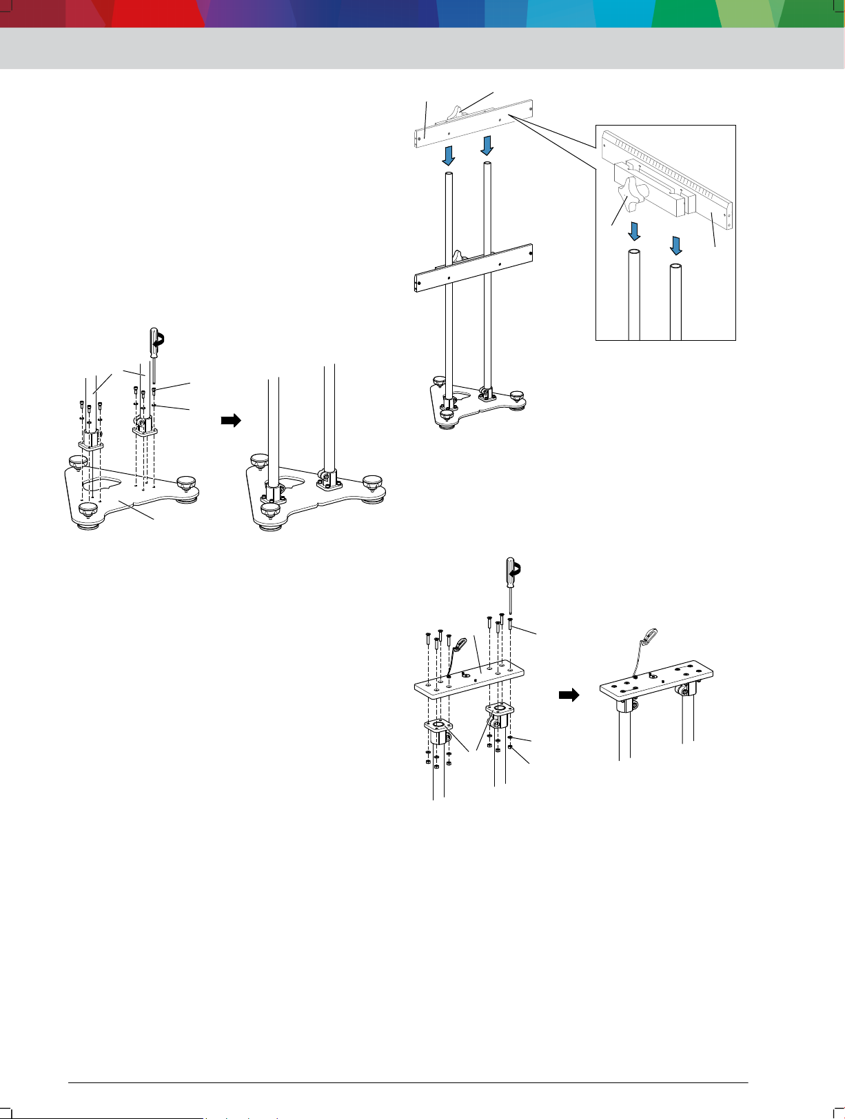
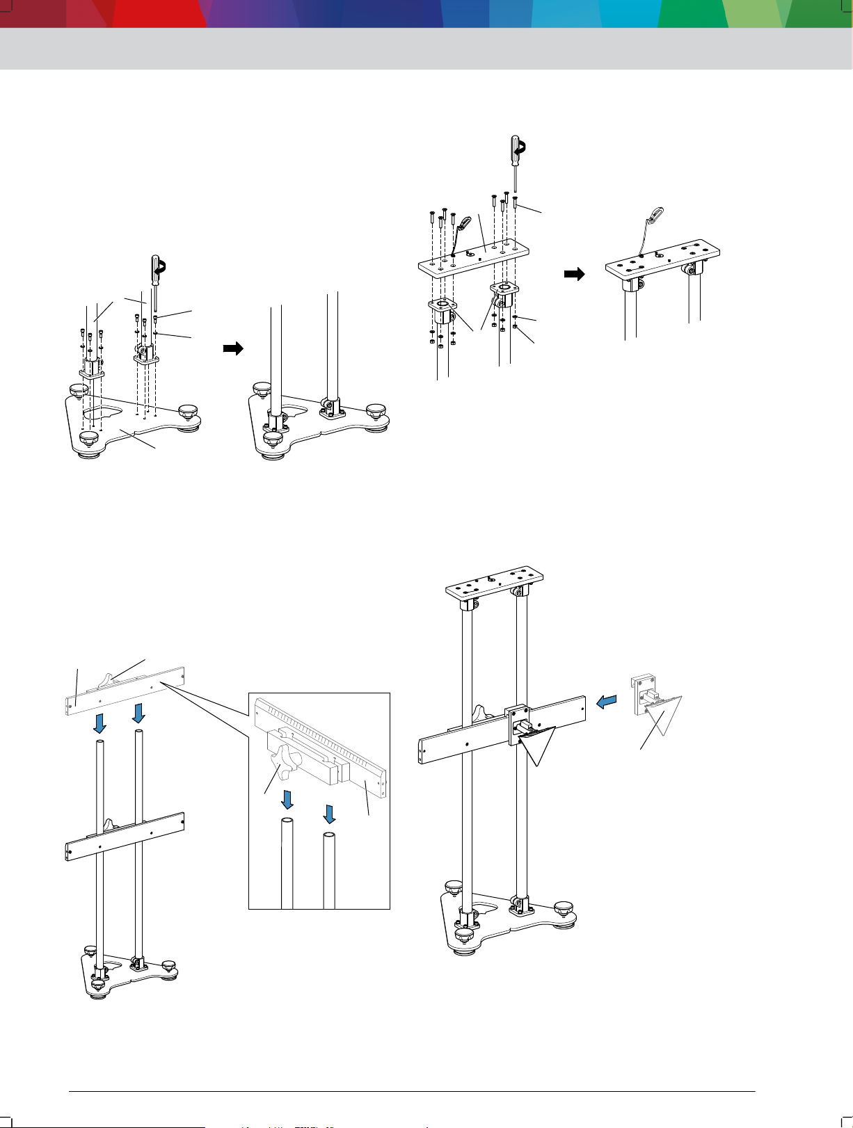
4: Führungsrohre befestigen
(1) Führungsrohre mit Rohrverbindern
(2) Grundplatte
(3) Innensechskantschraube
(4) Unterlegscheibe
Rohrverbinder, wie in 4512003-05_shd.svg 4 dargestellt, mit
3.
Innensechskantschrauben(3) und Unterlegscheiben
(4) an Grundplatte befestigen.
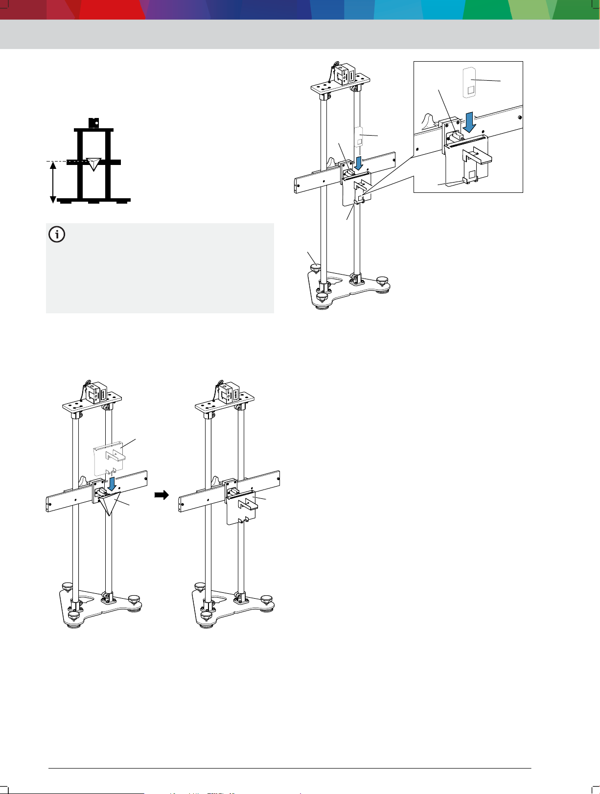
Vormontierter Klemmhalter 4512003-06_shd.svg 5 (1) auf die
4.
Führungsrohre schieben und mit Rändelschraube
4512003-06_shd.svg 5 (2) befestigen.
4 (1) über
Erstinbetriebnahme | SCT 815 | 5 | de
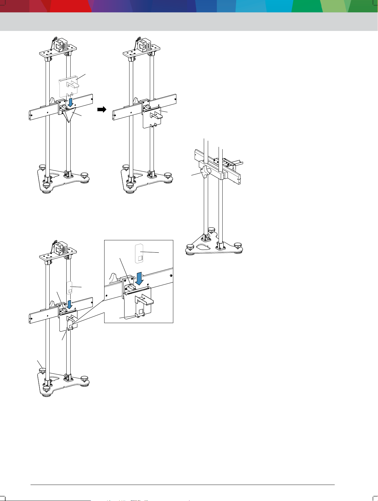
5: Klemmhalter befestigen
(1) Vormontierter Klemmhalter
(2) Rändelschraube
Aufnahme für Linienlaser 4512003-07_shd.svg 6 (1) mit den Bohrungen
5.
über den Rohrverbindern an der Führungsrohren
positionieren.
6: Aufnahme für Linienlaser befestigen
(1) Aufnahme für Linienlaser
(2) Rohrverbinder an Führungsrohren
(3) Senkschraube
(4) Unterlegscheibe
(5) Sechskantmutter
6. Aufnahme für Linienlaser, wie in 4512003-07_shd.svg 6 dargestellt, mit
Senkschrauben (3), Unterlegscheiben (4) und
Sechskantmuttern (5) an Rohrverbindern
befestigen.
7. Tripelspiegel 4512003-20_shd.svg 7 (1) auf Klemmhalter schieben.
1 689 989 362 | 2018-08-01Robert Bosch GmbH
1
11
1
2
3
de | 6 | SCT 815 | Bedienung
7: Tripelspiegel auf Klemmhalter schieben
(1) Tripelspiegel
Kunststoffschrauben 4512003-21_shd.svg 8 (1) an Klemmhalter
8.
befestigen.
Die Kunststoffschrauben dienen als Endschlag,
damit der Tripelspiegel nicht ausversehen vom
Klemmhalter geschoben werden kann. Im
Lieferumfang befinden sich 3
Kunststoffschrauben. Die dritte
Kunststoffschraube dient als Ersatz.
9: Positionsdaten aus Kurzanleitungen
(1) Entfernung zum Fahrzeug
(2) Höhe des Tripelspiegels
(3) Offset zur Fahrzeug-Längsmittelebene
VORSICHT - Verletzungsgefahr durch
herunterfallende Gegenstände.
2.
Linienlaser immer mit dem Fangseil sichern.
3.
SCT 815 mithilfe des Laser-Entfernungsmessers in
angegebener Entfernung zum Fahrzeug
positionieren. Entfernung von SCT 815 zum Fahrzeug einstellen 7 "Entfernung von SCT 815 zum
Fahrzeug einstellen"
4.
SCT 815 nach der Libelle an der Aufnahme für den
Linienlaser und der Libelle am Tripelspiegel
nivellieren.
5. SCT 815 mithilfe des Linienlasers zur FahrzeugLängsmittelebene ausrichten. SCT 815 zur Fahrzeug-Längsmittelebene ausrichten 8 "SCT 815 zur
Fahrzeug-Längsmittelebene ausrichten"
Nivellierung von SCT 815 sowie die Entfernung zum
6.
Fahrzeug überprüfen und gegebenenfalls
korrigieren.
Mithilfe des Laser-Entfernungsmessers die
7.
angegebene Höhe des Triplepspiegels einstellen. Höhe des Tripelspiegels einstellen
9 "Höhe des Tripelspiegels einstellen"
Tripelspiegel um den Offset zur Fahrzeug-
8.
Längsmittelebene auf dem Klemmhalter
verschieben. Offset (bis 25 cm) zur Fahrzeug-Längsmittelebene einstellen 10 "Offset (bis 25 cm) zur Fahrzeug-
Längsmittelebene einstellen"
— Falls der Offset zur Fahrzeug-Längsmittelebene
größer als 25cm ist, SCT 815 mithilfe von zwei
Hilfslinien um den entsprechenden Offset zur
Fahrzeugmittellängsachse verschieben. Offset (ab 25 cm) zur Fahrzeug-Längsmittelebene einstellen 10
"Offset (ab 25 cm) zur Fahrzeug-Längsmittelebene
einstellen"
Aufnahme für den Laser-Entfernungsmesser
9.
entfernen.
Linienlaser entfernen.
10.
Die metallischen Oberflächen der Aufnahme für
den Laser-Entfernungsmesser und des
Linienlasers können die Kalibrierung stören.
8: Kunststoffschrauben befestigen
(1) Kunststoffschrauben
---Separator---
4. Bedienung
4.1 SCT 815 für die RadarsensorKalibrierung positionieren
1. Positionsdaten für SCT 815 aus der entsprechenden
Kurzanleitung entnehmen.
1 689 989 362 | 2018-08-01 Robert Bosch GmbH
Radarsensor mithilfe einer Diagnose-Software
11.
kalibrieren.
---Separator---
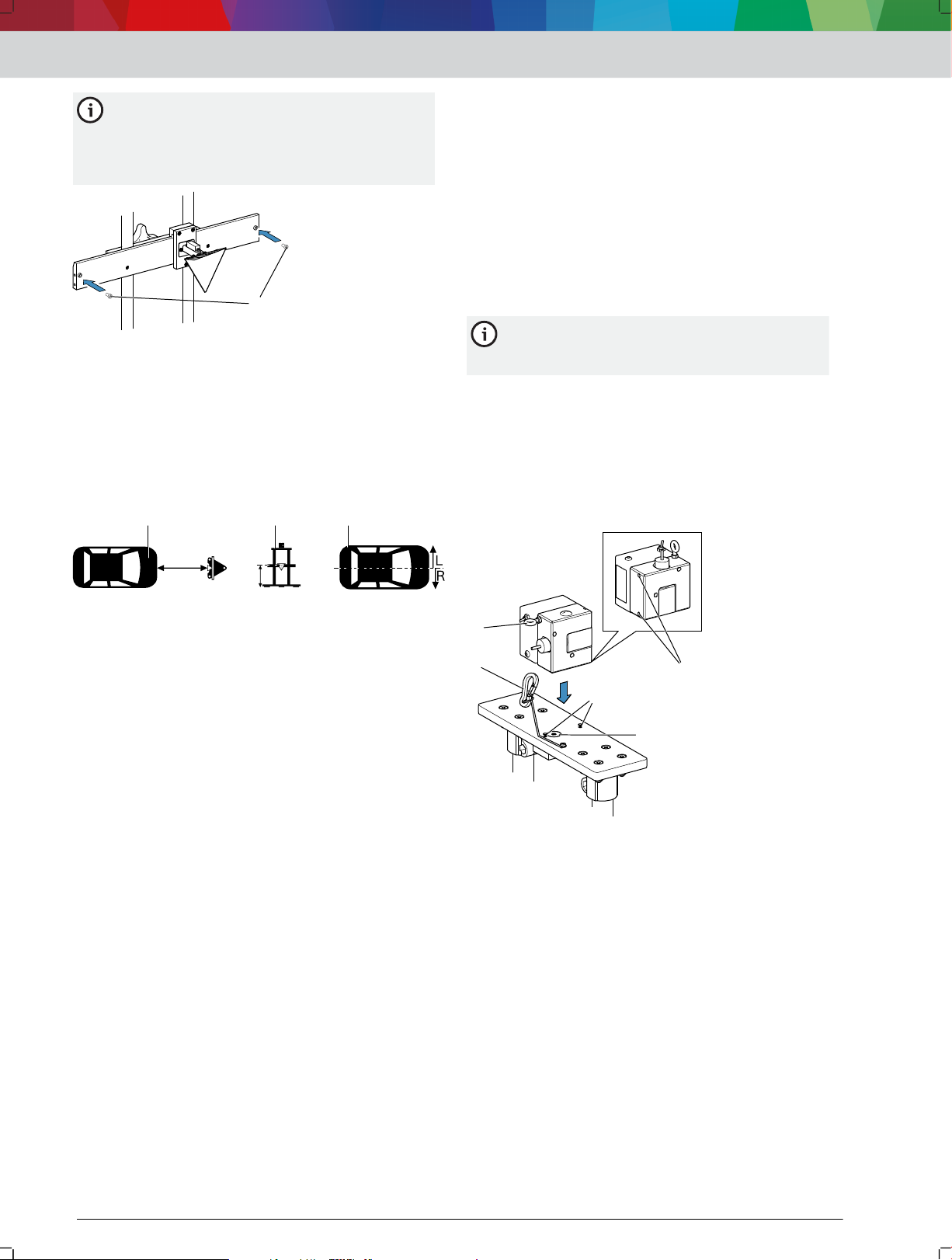
4.2 Linienlaser an SCT 815 befestigen
1. Positionierstifte 4512003-17_shd.svg 10 (1) an der Aufnahme für den
Linienlaser beachten.
2. Bohrbuchsen 4512003-17_shd.svg 10 (2) an der Unterseite des
Linienlasers beachten.
11
22
3
4
5
10: Linienlaser befestigen
1
2
1
1
2
3
4
1
2
3
(1) Positionierstifte
(2) Bohrbuchsen
(3) Magnet
(4) Fangseil
(5) Sicherungsring
Linienlaser mit den Bohrbuchsen auf den
3.
Positionierstiften positionieren.
Linienlaser wird durch den Magnet 4512003-17_shd.svg 10 (3) in der
Aufnahme angezogen.
Positionierstifte sitzen in den Bohrbuchsen des
Linienlasers.
Linienlaser sitzt fest auf der Aufnahme und kann
nicht verdreht werden.
Fangseil 4512003-17_shd.svg 10 (4) an der Aufnahme für den
4.
Linienlaser am Sicherungsring 4512003-17_shd.svg 10 (5) des
Linienlasers befestigen.
Linienlaser ist gegen Herunterfallen gesichert.
---Separator---
Bedienung | SCT 815 | 7 | de
12: Aufnahme für Laser-Entfernungsmesser positionieren
(1) Aufnahme für Laser-Entfernungsmesser
(2) Tripelspiegel
Laser-Entfernungsmesser 4512003-09_shd.svg 13 (1) in horizontaler
5.
Ablage 4512003-09_shd.svg 13 (2) einlegen.
4.3 Entfernung von SCT 815 zum Fahrzeug
einstellen
Die Entfernung von SCT 815 zum Fahrzeug wird in der
entsprechenden Kurzanleitung angegeben. Die
fahrzeugspezifische Entfernung befindet sich in der
Spalte mit folgendem Piktogramm.
11: Piktogramm für die Entfernung von SCT 815 zum Fahrzeug
1. Entsprechende Kurzanleitung verwenden.
2. Entfernung von SCT 815 zum entsprechenden
Fahrzeug herauslesen.
3. SCT 815 an den Führungsstangen anheben und nach
Augenmaß in der angegebenen Entfernung mittig vor
dem Fahrzeug positionieren.
4. Aufnahme für den Laser-Entfernungsmesser 4512003-08_shd.svg 12 (1)
auf Tripelspiegel 4512003-08_shd.svg 12 (2) positionieren.
13: Laser-Entfernungsmesser einlegen
(1) Laser-Entfernungsmesser
(2) Horizontale Ablage
(3) Libelle am Tripelspiegel
(4) Stellfuß
6. SCT 815 nach der Libelle am Tripelspiegel 4512003-09_shd.svg 13 (3)
mit dem Stellfuß 4512003-09_shd.svg 13 (4) nivellieren.
WARNUNG - Schwere Augenschäden durch
Laserstrahl.
1 689 989 362 | 2018-08-01Robert Bosch GmbH
1
2
3
11
22
33
4
1
2
3
4
de | 8 | SCT 815 | Bedienung
7. Niemals direkt in die Laserquelle sehen.
8. Zur Funktionskontrolle einen Gegenstand vor den
Austrittspunkt des Laser-Entfernungsmessers
halten.
9. Laser-Entfernungsmesser einschalten.
10. Höhe des Tripelspiegels so einstellen, dass der
Laserpunkt die Mitte der Stoßstange markiert.
Der Laser-Entfernungsmesser zeigt die aktuelle
Entfernung von SCT 815 zur Stoßstange an.
Der Laser-Entfernungsmesser misst
kontinuierlich die Entfernung. Bei einer
Positionsänderung von SCT 815 wird die neue
Entfernung zur Stoßstange auf dem Display des
Laser-Entfernungsmessers angezeigt.
Sicherstellen, dass der Laser-Entfernungsmesser mit
11.
Anschlag nach hinten an der horizontalen Ablage
liegt.
14: Laser-Entfernungsmesser am hinteren Anschlag
(1) Laser-Entfernungsmesser
(2) Hinterer Anschlag der horizontalen Ablage
(3) Aufnahme für den Laser-Entfernungsmesser
Es kommt zu Messfehlern, falls der LaserEntfernungsmesser nicht mit Anschlag nach
hinten in der horizontalen Ablage liegt.
SCT 815 mithilfe des Laser-Entfernungsmessers
12.
exakt in der angegebenen Entfernung vor dem
Fahrzeug positionieren.
SCT 815 ist richtig positioniert, sobald die
Angabe auf dem Laser-Entfernungsmesser mit
der Angabe aus der Kurzanleitung übereinstimmt.
---Separator---
4.4 SCT 815 zur Fahrzeug-Längsmittelebene
ausrichten
Linienlaser 4512003-13_shd.svg 15 (1) an der Aufnahme für den
1.
Linienlaser befestigen und mit dem Fangseil 4512003-13_shd.svg 15 (4)
sichern.
2. SCT 815 nach der Libelle an der Aufnahme für den
Linienlaser 4512003-13_shd.svg 15 (2) mit den Stellfüßen 4512003-13_shd.svg 15 (3)
nivellieren.
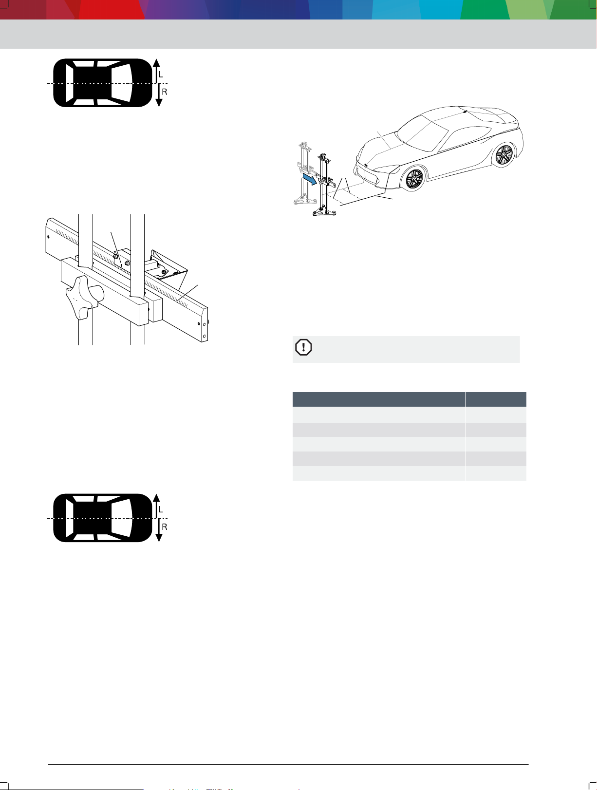
15: SCT 815 ausrichten
(1) Linienlaser
(2) Libelle an der Aufnahme für den Linienlaser
(3) Stellfüße
(4) Fangseil
WARNUNG - Schwere Augenschäden durch
Laserstrahl.
Niemals direkt in die Laserquelle sehen.
3.
Zur Funktionskontrolle einen Gegenstand vor den
4.
Austrittspunkt des Linienlasers halten.
Linienlaser einschalten.
5.
Laserlinie verläuft über das Fahrzeug.
SCT 815 so ausrichten, dass das Hersteller-Emblem
6.
an der Fahrzeugfront und die Antenne durch die
Laserlinie 4512003-14_shd.svg 16 (2) markiert werden.
16: SCT 815 auf Fahrzeug-Längsmittelebene ausrichten
(1) Linienlaser
(2) Projizierte Laserlinie
(3) Hersteller-Emblem
(4) Antenne
Je nach Fahrzeug können auch andere
Fixpunkte verwendet werden, um SCT 815 mit
dem Linienlaser zur Fahrzeug-Längsmittelebene
auszurichten.
---Separator---
1 689 989 362 | 2018-08-01 Robert Bosch GmbH
4.5 Höhe des Tripelspiegels einstellen
1
2
1
1
2
3
4
1
3
2
Die Höhe des Tripelspiegels wird in der
entsprechenden Kurzanleitung angegeben. Die
fahrzeugspezifische Höhe befindet sich in der Spalte
mit folgendem Piktogramm.
17: Piktogramm für die Höhe des Tripelspiegels
Die fahrzeugspezifische Höhe in der
Kurzanleitung ist gültig, wenn das Fahrzeug auf
der gleichen Fläche wie SCT 815 steht. Steht
das Fahrzeug auf einer Hebebühne oder einer
Nivellierfläche, muss diese Erhöhung gemessen
werden. Die gemessene Höhe muss zur
fahrzeugspezifischen Höhe aus der
Kurzanleitung hinzuaddiert werden.
Entsprechende Kurzanleitung verwenden.
1.
Höhe des Tripelspiegels zum entsprechenden
2.
Fahrzeug herauslesen.
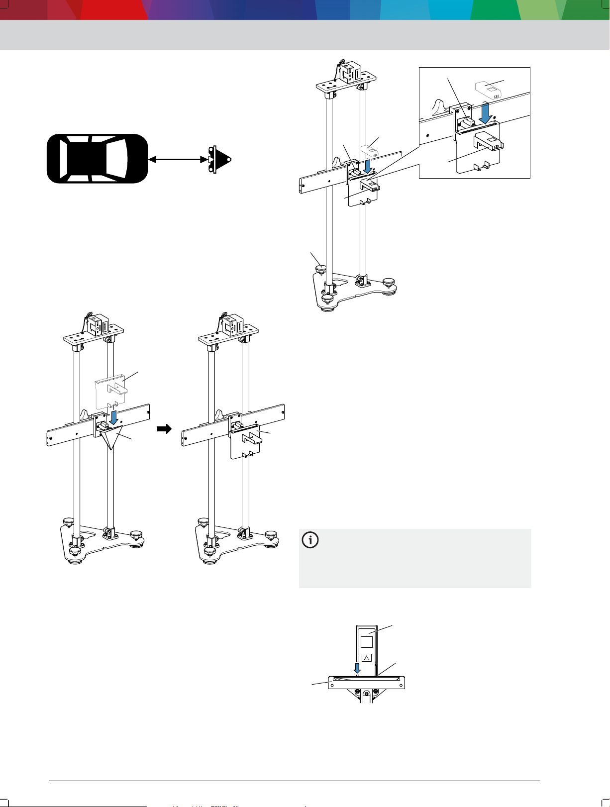
Aufnahme für den Laser-Entfernungsmesser 4512003-08_shd(2).svg 18 (1)
3.
auf Tripelspiegel 4512003-08_shd(2).svg 18 (2) positionieren.
Bedienung | SCT 815 | 9 | de
19: Laser-Entfernungsmesser einlegen
(1) Laser-Entfernungsmesser
(2) Vertikale Ablage
(3) Libelle am Tripelspiegel
(4) Stellfuß
SCT 815 nach der Libelle am Tripelspiegel 4512003-11_shd.svg 19 (3)
5.
mit dem Stellfuß 4512003-11_shd.svg 19 (4) nivellieren.
WARNUNG - Schwere Augenschäden durch
Laserstrahl.
Niemals direkt in die Laserquelle sehen.
6.
Zur Funktionskontrolle einen Gegenstand vor den
7.
Austrittspunkt des Laser-Entfernungsmessers
halten.
Laser-Entfernungsmesser einschalten.
8.
Der Laser-Entfernungsmesser zeigt die aktuelle
Entfernung des Tripelspiegels vom Boden an.
VORSICHT - Quetschgefahr beim Einstellen der Höhe
des Tripelspiegels.
Keine Finger zwischen Klemmhalter und
9.
Führungsrohre bringen.
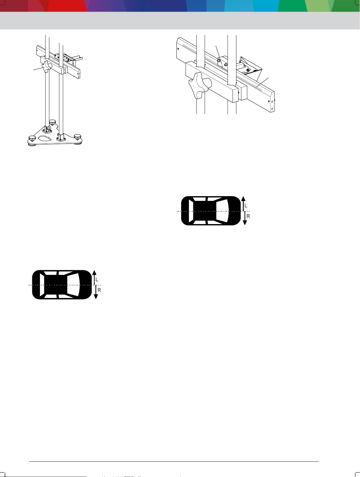
Rändelschraube 4512003-12_shd.svg 20 (1) am Klemmhalter lockern,
10.
bis der Tripelspiegel in der Höhe eingestellt werden
kann.
18: Aufnahme für Laser-Entfernungsmesser positionieren
(1) Aufnahme für Laser-Entfernungsmesser
(2) Tripelspiegel
4. Laser-Entfernungsmesser 4512003-11_shd.svg 19 (1) in vertikaler
Ablage 4512003-11_shd.svg 19 (2) einlegen.
1 689 989 362 | 2018-08-01Robert Bosch GmbH
1
1
2
de | 10 | SCT 815 | Bedienung
22: Offset bis 25 cm einstellen
(1) Lineal am Klemmhalter
(2) Pfeil am Tripelspiegel für die exakte Offset-Einstellung
---Separator---
20: Höhe des Tripelspiegels einstellen
(1) Rändelschraube
11.
Tripelspiegel mithilfe des Laser-Entfernungsmessers
exakt in fahrzeugspezifischer Höhe positionieren.
— Bei Erhöhung des Fahrzeugs durch eine
Hebebühne oder Nivellierfläche die Erhöhung
messen und zur fahrzeugspezifischen Höhe
hinzuaddieren.
Klemmhalter mit der Rändelschraube fixieren.
12.
---Separator---
4.6 Offset (bis 25 cm) zur Fahrzeug-
Längsmittelebene einstellen
Der Offset des Tripelspiegels zur FahrzeugLängsmittelebene wird in der entsprechenden
Kurzanleitung angegeben. Der fahrzeugspezifische
Offset befindet sich in der Spalte mit folgendem
Piktogramm.
21: Piktogramm für den Offset des Tripelspiegels
SCT 815 muss zur Fahrzeug-Längsmittelebene
ausgerichtet sein.
Entsprechende Kurzanleitung verwenden.
1.
Offset von SCT 815 zum entsprechenden Fahrzeug
2.
herauslesen.
3. Offset desTripelspiegels anhand des Lineals am
Klemmhalter 4512003-15_shd.svg 22 (1) einstellen.
4.7 Offset (ab 25 cm) zur FahrzeugLängsmittelebene einstellen
Der Offset des Tripelspiegels zur FahrzeugLängsmittelebene wird in der entsprechenden
Kurzanleitung angegeben. Der fahrzeugspezifische
Offset befindet sich in der Spalte mit folgendem
Piktogramm.
23: Piktogramm für den Offset des Tripelspiegels
SCT 815 muss zur Fahrzeug-Längsmittelebene
ausgerichtet sein.
Entsprechende Kurzanleitung verwenden.
1.
Offset von SCT 815 zum entsprechenden Fahrzeug
2.
herauslesen.
WARNUNG - Schwere Augenschäden durch
Laserstrahl.
Niemals direkt in die Laserquelle sehen.
3.
Zur Funktionskontrolle einen Gegenstand vor den
4.
Austrittspunkt des Linienlasers halten.
SCT 815 zur Fahrzeug-Längsmittelebene ausrichten. SCT 815 zur Fahrzeug-Längsmittelebene ausrichten
5.
8 "SCT 815 zur Fahrzeug-Längsmittelebene
ausrichten"
6.
Zwei Hilfslinien 4512003-16_shd.svg 24 (2) mit der Länge des
angegebenen Offsets im rechten Winkel zu der
projizierten Laserlinie 4512003-16_shd.svg 24 (1) zeichnen.
7. Eine parallele Linie zu der projizierten Laserlinie
mithilfe der zwei Hilfslinien zeichnen.
8. SCT 815 verschieben, bis die projizierte Laserlinie
des Linienlasers auf der parallel gezeichneten Linie
verläuft.
1 689 989 362 | 2018-08-01 Robert Bosch GmbH

1
22
3
24: Offset ab 25 cm einstellen
1
2
3
(1) Laserlinie auf Fahrzeug-Längsmittelebene
(2) Hilfslinien
(3) Um Offset verschobene Laserlinie
---Separator---
5. Instandhaltung
5.1 Reinigung
SCT 815 nur mit neutralen Reinigungsmitteln und
weichen Tüchern säubern.
Grobe Werkstattputzlappen und scheuernde
Reinigungsmittel können SCT 815 beschädigen.
---Separator---
5.2 Ersatzteile
Benennung Teilenummer
Tripelspiegel
Aufnahme für Laser-Entfernungsmesser 1 680 423 011
Laser-Entfernungsmesser GLM 20 1 687 010 600
Linienlaser P-Assist S5 1 690 381 124
Teilesatz Stellfüße 1 687 010 599
---Separator---
<)
Verschleißteil
---Separator---
<)
5.3 Stellfuß wechseln
Defekten Stellfuß entfernen.
1.
Einen Stellfuß des Ersatzteilsatzes verwenden.
2.
Gewinde des unteren Teils des Stellfußes 4512003-23_shd.svg 25 (3)
3.
durch die Bohrung an der Grundplatte führen.
Mutter 4512003-23_shd.svg 25 (2) auf das Gewinde drehen.
4.
Rändelschraube des Stellfußes 4512003-23_shd.svg 25 (1) bis zum
5.
Anschlag auf das Gewinde drehen.
Mutter, die zuvor auf das Gewinde gedreht wurde,
6.
gegen die Rändelschraube kontern.
1 685 350 017
Instandhaltung | SCT 815 | 11 | de
25: Stellfuß wechseln
(1) Rändelschraube des Stellfußes
(2) Mutter
(3) Unterer Teil des Stellfußes mit Gewinde
---Separator---
6. Außerbetriebnahme
6.1 Ortswechsel
Bei Weitergabe von SCT 815 die im Lieferumfang
vorhandene Dokumentation vollständig mit
übergeben.
SCT 815 nur in Originalverpackung oder
gleichwertiger Verpackung transportieren.
Hinweise zur Erstinbetriebnahme beachten.
---Separator---
6.2 Entsorgung und Verschrottung
SCT 815 zerlegen, nach Material sortieren und gemäß
den geltenden Vorschriften entsorgen.
---Separator---
7. Technische Daten
7.1 Maße und Gewicht
Eigenschaft Wert
Abmessungen Höhe x Breite x Tiefe 1230 mm x 600 mm
Gewicht 11.9 kg
---Separator---
x 510 mm
1 689 989 362 | 2018-08-01Robert Bosch GmbH
en | 12 | SCT 815
1 User instructions... ...................................... 12
1.1 Symbols in the documentation... .................. 12
1.2 Warnings in the documentation... ................. 12
1.3 Target group... .............................................. 12
1.4 Warranty and liability... ................................. 12
1.5 Safety Notes... .............................................. 13
1.6 Related documents... .................................... 13
2 Product description... .................................. 13
2.1 Intended Use... ............................................. 13
2.2 Product versions... ........................................ 13
2.3 Scope of delivery... ....................................... 13
2.4 Overview SCT 815... ..................................... 14
2.5 Prerequisites... .............................................. 14
2.6 Laser range finder GLM20... ......................... 14
2.7 Functional description... ............................... 14
3 Initial Operation
... .......................................
15
3.1 Installing the SCT 815... ............................... 15
4 Operation
... ..................................................
16
4.1 Positioning the SCT 815 for radar sensor
calibration... ................................................. 16
4.2 Attaching the line laser to the SCT 815... ..... 16
4.3 Adjusting the distance between the SCT 815
and the vehicle... .......................................... 17
4.4 Aligning the SCT 815 with the vehicle's
longitudinal center plane... ........................... 18
4.5 Adjusting the height of the prismatic
reflector... ..................................................... 18
4.6 Setting the offset (up to 25cm) from the
vehicle's longitudinal center plane... ............ 19
4.7 Setting the offset (25cm and above) from the
vehicle's longitudinal center plane... ............ 20
5 Maintenance... ............................................. 20
5.1 Cleaning... ..................................................... 20
5.2 Spare parts... ................................................ 20
5.3 Changing the positioning foot... ................... 20
6 Decommissioning... ..................................... 21
6.1 Changing location... ...................................... 21
6.2 Disposal and scrapping... ............................. 21
7 Technical specifications... ........................... 21
7.1 Dimensions and weights... ............................ 21
1. User instructions
1.1 Symbols in the documentation
Warning of possible physical damage to the component,
product or environmental pollution.
Practical hints, recommendation or reference to other
information
Warning of possible danger for the operator during
subsequent procedures
Single-step procedure
Optional step
Result of a procedure
Reference to a figure. Example: 12(2) means
figure 12, item 2
Reference to a page.
1.2 Warnings in the documentation
Warning notices warn of dangers to the user or people
in the vicinity. Warnings also indicate the type, source
and consequences of the danger as well as preventive
action.
Warning notices have the following structure:
Signal word
Warning
symbol
The signal word indicates the likelihood of occurrence
and the severity of the danger in the event of nonobservance:
Signal word Likelihood of
DANGER Immediate threat of
WARNING Possible impending
CAUTION Possible dangerous
1.3 Target group
The product may be used only by skilled and instructed
personnel. Apprentices or personnel undergoing
training or instruction may use the product only under
the continual supervision of an experienced person.
Children must be supervised to ensure that they do not
play with the product.
---Separator---
Type, source and consequences of the
danger.
Actions and instructions to prevent the
danger.
occurrence
danger
danger
situation
Severity of danger with
non-observance
Death or severe injury
Death or severe injury
Minor injury
1.4 Warranty and liability
No modifications may be carried out on our products.
Our products may only be used with genuine
accessories and genuine spare parts. Otherwise, all
warranty claims will be rendered null and void.
---Separator---
1 689 989 362 | 2018-08-01 Robert Bosch GmbH
Product description | SCT 815 | 13 | en
1.5 Safety Notes
WARNING
Severe eye damage from laser beam. Death or
severe injury.
Never look directly into the laser source.
Never point the laser beam at people,
particularly at their faces or eyes.
To test function, hold an object in front of the
exit point of the laser range finder and line
---Separator---
laser.
CAUTION
Risk of injury from objects falling from the
SCT 815. Minor injury.
Wear safety shoes.
Always use the arrestor cable to secure the line
---Separator---
laser.
CAUTION
Risk of crushing when adjusting the height of
the prismatic reflector. Minor injury.
While the height of the prismatic reflector is
being adjusted, do not place fingers between
---Separator---
the tool holder and the guide tubes.
1.6 Related documents
1 690 386 038 – P-Assist S5 original operating
•
instructions
1 689 989 376 – GLM 20 original operating
•
instructions
1 689 989 363 – Honda brief instructions
•
1 689 989 364 – Toyota brief instructions
•
1 689 989 365 – Mazda brief instructions
•
1 689 989 366 – Kia brief instructions
•
1 689 989 367 – Hyundai brief instructions
•
---Separator---
Equipment version Line laser P-
Assist S5
SCT 815 – –
SCT 815 S1 – •
SCT 815 S2 • •
– not included in scope of delivery
• included in scope of delivery
Laser range
GLM 20
finder
The product versions are all referred to as SCT 815 in
the following.
---Separator---
2.3 Scope of delivery
Designation Part number
Base plate 1 688 000 368
Guide tubes 1 680 700 313
Line laser mount 1 681 038 414
Tool holder for prismatic reflector 1 688 040 319
3 plastic screws 1 683 414 021
Prismatic reflector 1 685 350 017
Mount for laser range finder 1 680 423 011
Laser range finder GLM 20* 1 687 010 600
Line laser P-Assist S5* 1 690 381 124
Original operating instructions 1 689 989 362
Honda brief instructions 1 689 989 363
Toyota brief instructions 1 689 989 364
Mazda brief instructions 1 689 989 365
Kia brief instructions 1 689 989 366
Hyundai brief instructions 1 689 989 367
8 hex socket head cap screws, 16 washers, 8
countersunk bolts, 8 hexagon nut
---Separator---
* depends on the product version
---Separator---
1 687 010 613
2. Product description
2.1 Intended Use
SCT 815, SCT 815 S1 and SCT 815 S2 are adjustment
devices for calibrating the front radar sensors of the
following makes:
• Mazda
Honda
•
• Toyota
• KIA
•
Hyundai
In conjunction with diagnostic software, the front radar
sensor can be calibrated for the ACC (adaptive cruise
control) and the emergency braking assistance.
Any other use is considered improper use and is
not permissible.
---Separator---
2.2 Product versions
The SCT 815 is available in three equipment versions.
The equipment versions differ in their scope of
delivery. Depending on the equipment version, 0, 1 or
2 lasers are included.
1 689 989 362 | 2018-08-01Robert Bosch GmbH
1
2
3
3
4
5
6
7
8
5 – 10 m
4 – 5 m
1
2
en | 14 | SCT 815 | Product description
2.4 Overview SCT 815
Diagnostic software
• Diagnostic software for calibrating the front radar
sensor
• If [ESI]tronic 2.0 is used as diagnostic software: info
type SD (control unit diagnosis) and a KTS
---Separator---
2.6 Laser range finder GLM20
The laser range finder GLM 20 is used to position the
SCT 815 in front of the vehicle and to adjust the height
of the prismatic reflector.
The following properties of the laser range finder
GLM 20 ensure that the SCT 815 can be positioned
precisely as specified in the brief instructions specific
to the vehicle:
•
Continuous distance measurement
• Rear edge as reference point for distance
measurement
For the equipment version SCT 815 (laser not
included in the scope of delivery), the GLM 20
is recommended as a laser range finder.
1: SCT 815
(1) Base plate
(2) Tool holder for prismatic reflector
(3) Guide tubes
(4) Line laser mount
(5) Line laser P-Assist S5
(6) Laser range finder GLM 20
(7) Prismatic reflector
(8) Mount for laser range finder
---Separator---
2.5 Prerequisites
Measurement bay
Maximum unevenness at the measurement bay:
•
1 mm
Maximum unevenness at the resting surface of the
•
vehicle: 10 mm
Required free space in front of the vehicle: 5–10 m
•
long / 4–5 m wide
2: Free space in front of the vehicle
• The free space in front of the vehicle must not
contain metallic objects.
---Separator---
The SCT 815 is positioned within the free space
in front of the vehicle. Metallic objects interfere
with front radar sensor calibration.
All properties and functions of the GLM 20 are
described in the original operating instructions
1 689 989 376. If any other laser range finder than the
GLM 20 is used, the following conditions must be met:
Rear edge as reference point for distance
•
measurement
3: Reference point for distance measurement
(1) Rear edge as reference point for distance measurement
(2) Laser exit point
Exact length: 100 mm
•
Maximum width: 46 mm
•
Maximum height: 18 mm
•
For laser range finders with a different length,
the specifications for the distance from the
vehicle and the height of the prismatic reflector
found in the vehicle-specific brief instructions
must be converted. Laser range finders with a
different width or height will not fit into the
mount.
---Separator---
2.7 Functional description
A prismatic reflector must be used to calibrate the
front radar sensor of the makes Mazda, Honda, Toyota,
Kia and Hyundai. For the front radar sensor to be
calibrated, the prismatic reflector must be positioned
in front of the vehicle at a distance and height specific
to that vehicle. The adjustment device SCT 815 is used
to put the prismatic reflector in that vehicle-specific
position.
As soon as the prismatic reflector is in its vehicle-
specific position, the calibration must be started using
diagnostic software. The front radar sensor emits
signals focused and reflected back to the front radar
sensor by the reflective prism. The calibration will be
successful if the reflective prism is precisely aligned.
The calibration may fail if the reflective prism is not
1 689 989 362 | 2018-08-01 Robert Bosch GmbH
11
2
3
4
6 Nm
1
2
2
1
1
2
2
3
4
5
6 Nm
1
Initial Operation | SCT 815 | 15 | en
precisely aligned or the measurement bay
requirements are not met (Voraussetzungen 14 "Prerequisites" ).
---Separator---
3. Initial Operation
3.1 Installing the SCT 815
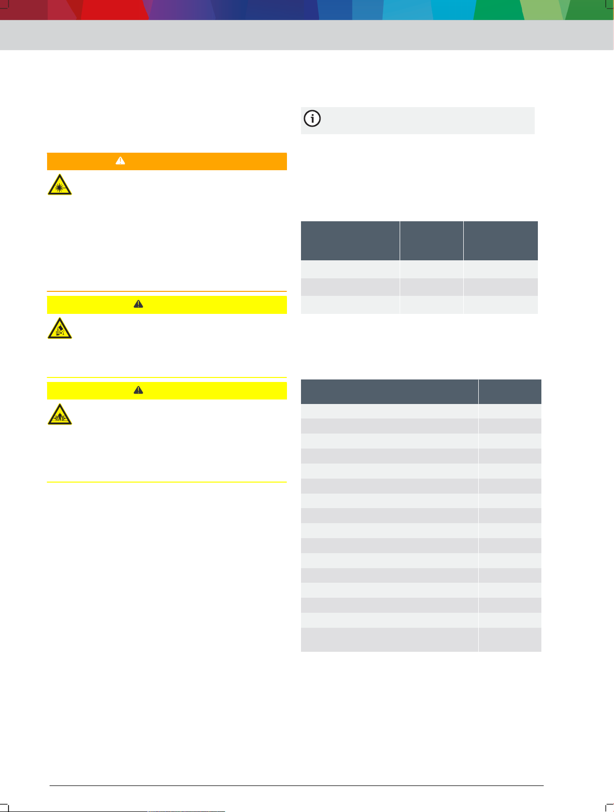
1. Make sure all components specified in the scope of
delivery are present.
2. Position the guide tube with the tube connectors
over the holes in the base plate 4512003-05_shd.svg 4 (1).
4: Securing the guide tubes
(1) Guide tube with tube connectors
(2) Base plate
(3) Hex socket head cap screw
(4) Washer
Using hex socket head cap screw(3) and washer (4)
3.
fasten the tube connector to the base plate as
shown in 4512003-05_shd.svg 4 .
Slide the preassembled tool holder 4512003-06_shd.svg 5 (1) onto the
4.
guide tubes, and use the knurled screw 4512003-06_shd.svg 5 (2) to
secure it.
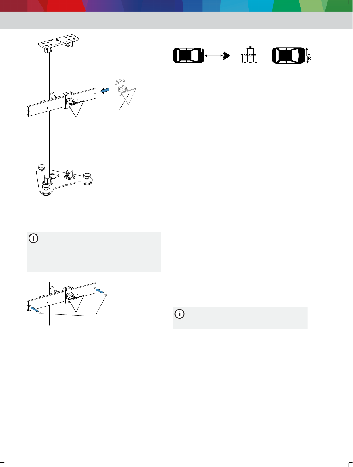
5. Using the holes, position the line laser mount over
the tube connectors on the guide tubes 4512003-07_shd.svg 6 (1).
6: Attaching the line laser mount
(1) Line laser mount
(2) Tube connector on guide tubes
(3) Countersunk bolt
(4) Washer
(5) Hex nut
Using countersunk bolt (3), washer (4) and hex nut
6.
(5), fasten the mount for the line laser to the tube
connectors as shown in 4512003-07_shd.svg 6 .
Slide the prismatic reflector 4512003-20_shd.svg 7 (1) onto the tool
7.
holder.
5: Attaching the tool holder
(1) Preassembled tool holder
(2) Knurled screw
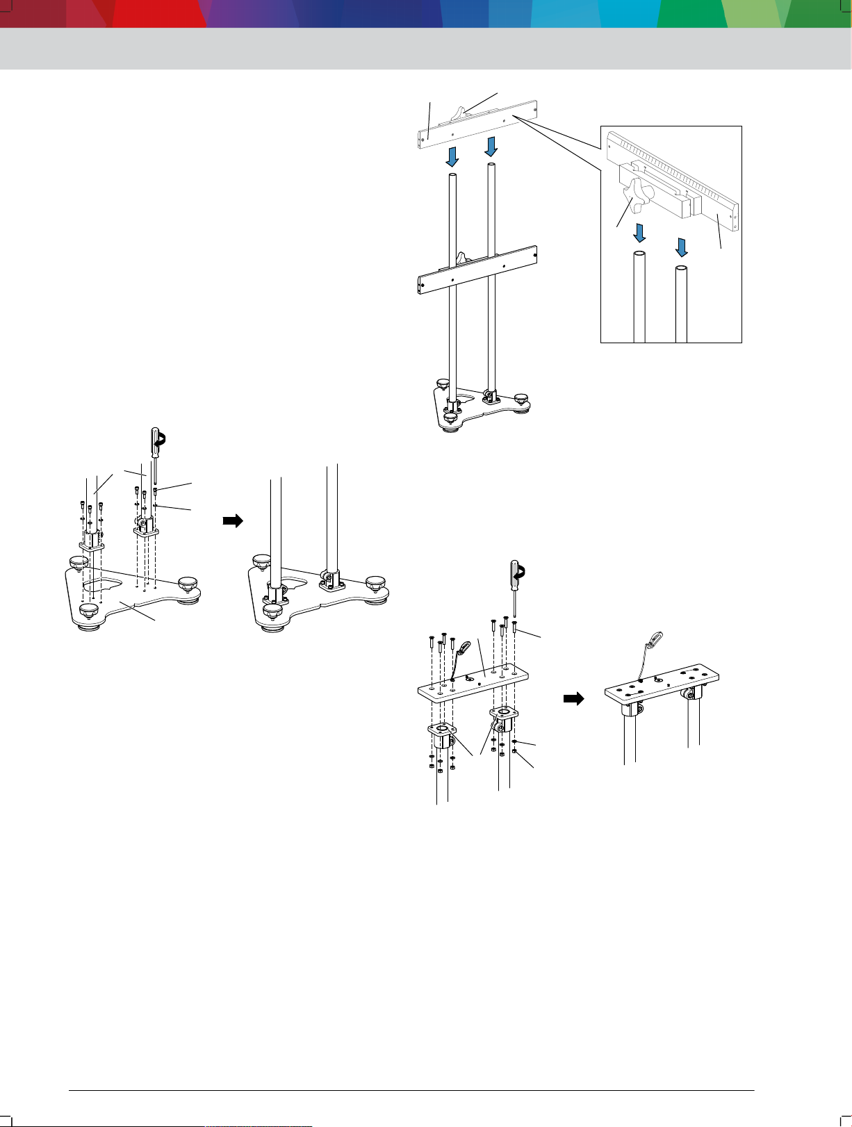
7: Sliding the prismatic reflector onto the tool holder
(1) Prismatic reflector
8. Secure the plastic screws 4512003-21_shd.svg 8 (1) on the tool holder.
1 689 989 362 | 2018-08-01Robert Bosch GmbH
11
1
2
3
11
22
3
4
5
en | 16 | SCT 815 | Operation
The plastic screws are intended as a stop so the
prismatic reflector cannot slide off the tool
holder by accident. 3 plastic screws are
included in the scope of delivery. The third
plastic screw is intended as a spare.
8: Securing the plastic screws
(1) Plastic screws
---Separator---
4. Operation
4.1 Positioning the SCT 815 for radar
sensor calibration
1.
For position information for the SCT 815, refer to
the corresponding brief instructions.
8. Move the prismatic
reflector on the tool holder
according to the offset from the vehicle's
longitudinal center plane. Offset (bis 25 cm) zur Fahrzeug-Längsmittelebene einstellen 19 "Setting the offset (up
to 25cm) from the vehicle's longitudinal center plane"
— If the offset from the vehicle's longitudinal center
plane is more than 25 cm, use two auxiliary lines
to move the SCT 815 according to the offset from
the vehicle's longitudinal center plane. Offset (ab 25 cm) zur Fahrzeug-Längsmittelebene einstellen 20
"Setting the offset (25cm and above) from the
vehicle's longitudinal center plane"
9.
Remove the mount for the laser range finder.
10.
Remove the line laser.
The metallic surfaces of the mounts for the
laser range finder and the line laser may
interfere with calibration.
11. Use diagnostic software to calibrate the radar
sensor.
---Separator---
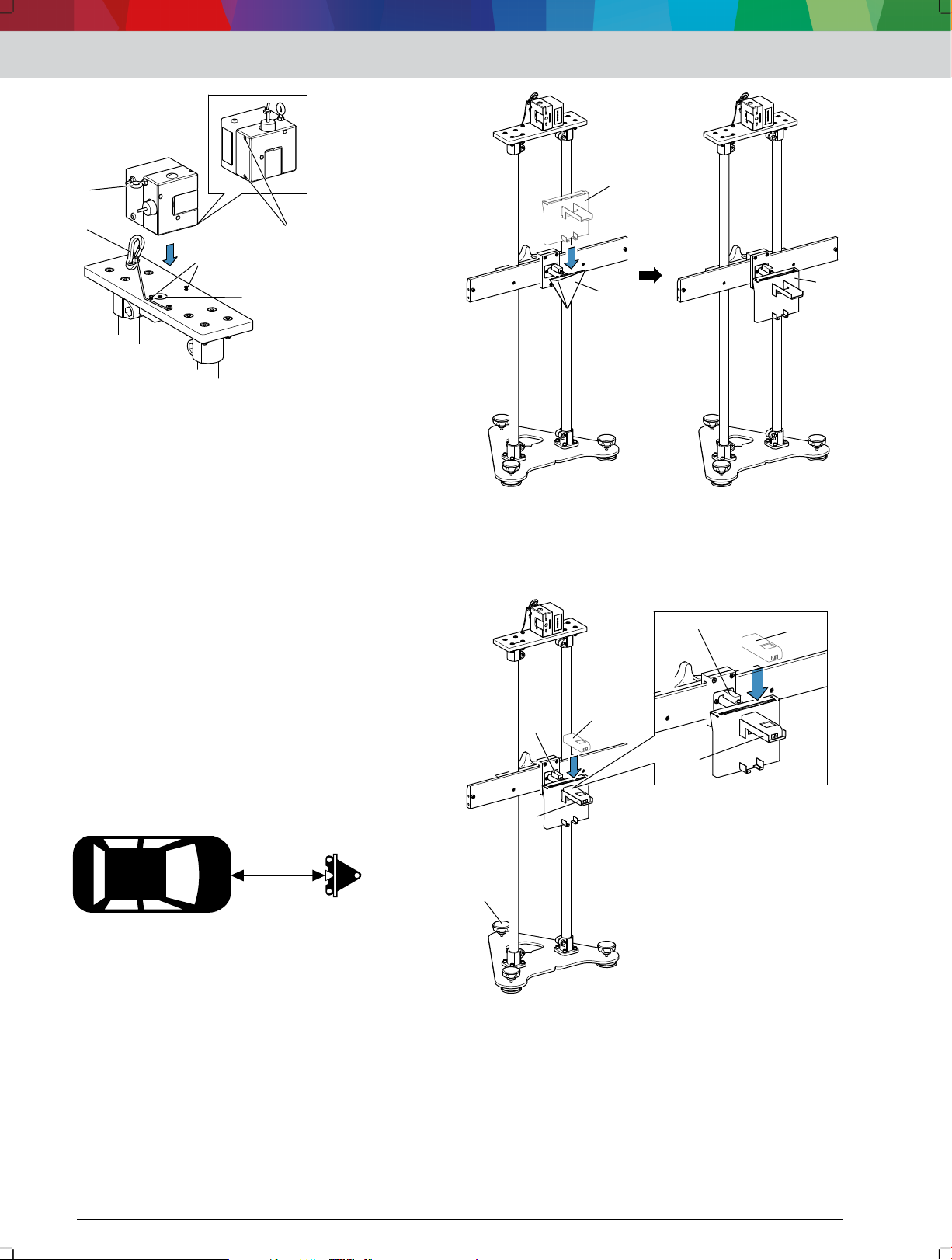
4.2 Attaching the line laser to the SCT 815
1.
Pay attention to the positioning pins 4512003-17_shd.svg
line laser mount.
2. Pay attention to the drill bushings 4512003-17_shd.svg 10 (2) on the
bottom of the line laser.
10 (1) on the
9: Position information from brief instructions
(1) Distance from the vehicle
(2) Height of the prismatic reflector
(3) Offset from the vehicle's longitudinal center plane
CAUTION – Risk of injury from falling objects.
Always use the arrestor cable to secure the line
2.
laser.
Use the laser range finder to position the SCT 815 at
3.
the specified distance from the vehicle. Entfernung von SCT 815 zum Fahrzeug einstellen 17
"Adjusting the distance between the SCT 815 and the
vehicle"
Use the spirit level on the line laser mount and the
4.
spirit level on the prismatic reflector to align the
SCT 815.
Use the line laser to align the SCT 815 with the
5.
vehicle's longitudinal center plane. Aligning the SCT 815 zur Fahrzeug-Längsmittelebene ausrichten 18
"Aligning the SCT 815 with the vehicle's longitudinal
center plane"
6.
Check the alignment of the SCT 815 and the
distance from the vehicle, and adjust them if
necessary.
7. Use the laser range finder to set the specified height
of the prismatic reflector. Höhe des Tripelspiegels einstellen 18 "Adjusting the height
of the prismatic reflector"
10: Attaching the line laser
(1) Positioning pins
(2) Drill bushings
(3) Magnet
(4) Arrestor cable
(5) Retaining ring
3. Position the line laser with the drill bushings on the
positioning pins.
The line laser is pulled in by the magnet 4512003-17_shd.svg 10 (3)
in the mount.
The positioning pins are in the drill bushings of
the line laser.
The line laser sits firmly in the mount and cannot
be twisted.
4. Secure the arrestor cable 4512003-17_shd.svg 10 (4) on the line laser
mount to the retaining ring 4512003-17_shd.svg 10 (5) of the line laser.
The line laser is secured against falling.
---Separator---
1 689 989 362 | 2018-08-01 Robert Bosch GmbH
4.3 Adjusting the distance between the
1
2
1
1
2
3
4
1
2
3
1
2
3
SCT 815 and the vehicle
The distance between the SCT 815 and the vehicle is
specified in the corresponding brief instructions. The
distance specific to the vehicle is found in the column
with the following pictogram.
11: Pictogram for the distance between SCT 815 and the
vehicle
Use the corresponding brief instructions.
1.
2.
Look up the distance between the SCT 815 and the
relevant vehicle.
3.
Lift the SCT 815 on the guide tubes, and position it
at the specified distance in front of the center of the
vehicle by eye.
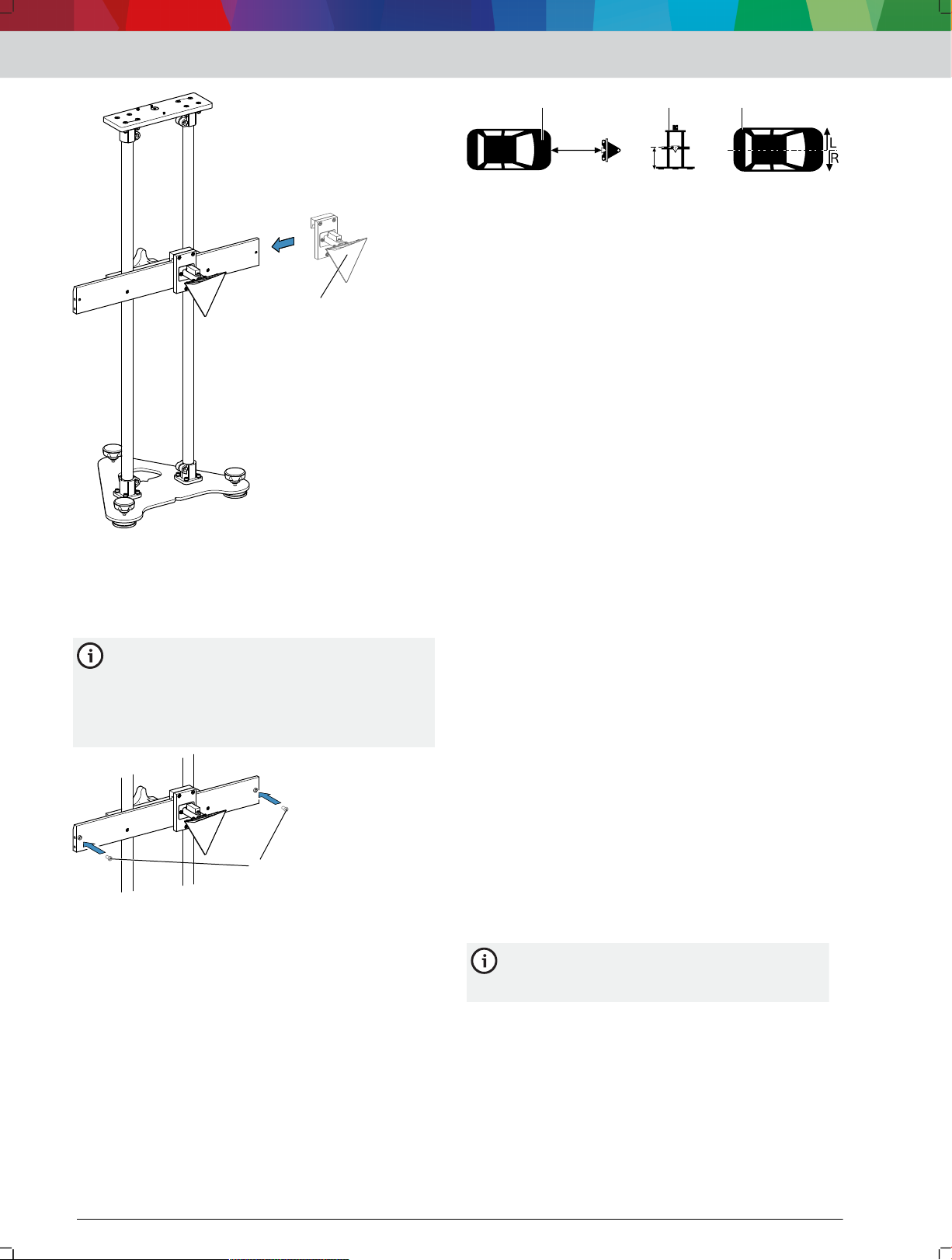
4.
Position the mount for the laser range finder 4512003-08_shd.svg
(1) on the prismatic reflector 4512003-08_shd.svg 12 (2).
12
Operation | SCT 815 | 17 | en
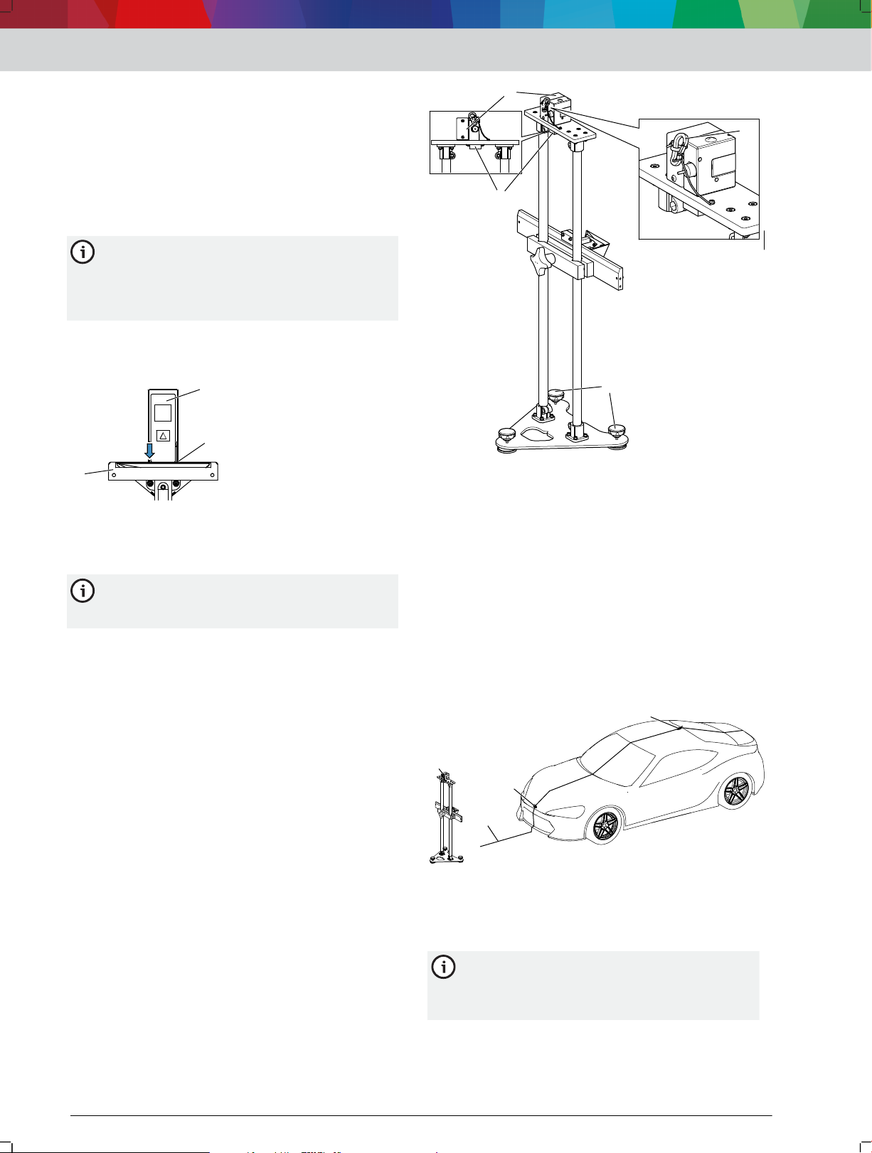
13: Inserting the laser range finder
(1) Laser range finder
(2) Horizontal tray
(3) Spirit level on the prismatic reflector
(4) Positioning foot
Use the positioning foot 4512003-09_shd.svg 13 (4) and the spirit level
6.
on the prismatic reflector 4512003-09_shd.svg 13 (3) to level the
SCT 815.
WARNING – severe eye damage from laser beam.
Never look directly into the laser source.
7.
To test function, hold an object in front of the exit
8.
point of the laser range finder.
Switch on the laser range finder.
9.
Adjust the height of the prismatic reflector in such a
10.
way that the laser point marks the center of the
bumper.
The laser range finder indicates the current
distance between the SCT 815 and the bumper.
The laser range finder measures distance
continuously. If the position of the SCT 815
changes, the new distance from the bumper
12: Positioning the mount for the laser range finder
(1) Mount for laser range finder
(2) Prismatic reflector
5. Insert the laser range finder 4512003-09_shd.svg 13 (1) into the
horizontal tray 4512003-09_shd.svg 13 (2).
will be shown on the display of the laser range
finder.
11. Make sure the back of the laser range finder touches
the rear stop of the horizontal tray.
14: Laser range finder at the rear stop
(1) Laser range finder
(2) Rear stop of the horizontal tray
(3) Mount for laser range finder
1 689 989 362 | 2018-08-01Robert Bosch GmbH
11
22
33
4
1
2
3
4
en | 18 | SCT 815 | Operation
If the back of the laser range finder does not
touch the rear stop of the horizontal tray, there
will be observational errors.
12. Use the laser range finder to position the SCT 815
at the precise specified distance from the front of
the vehicle.
The position of the SCT 815 is correct when the
laser range finder reading matches the
specification from the brief instructions.
---Separator---
4.4 Aligning the SCT 815 with the vehicle's
longitudinal center plane
1.
Attach the line laser 4512003-13_shd.svg
and use the arrestor cable 4512003-13_shd.svg 15 (4) to secure it.
2. Use the spirit level on the line laser mount 4512003-13_shd.svg 15 (2)
and the positioning feet 4512003-13_shd.svg
SCT 815.
15 (1) to the line laser mount,
15 (3) to level the
16: Aligning the SCT 815
(1) Line laser
(2) Projected laser line
(3) Manufacturer badge
(4) Antenna
Depending on the vehicle, other fixed points
can be used to align the SCT 815 with the
vehicle's longitudinal center plane using the line
laser.
---Separator---
4.5 Adjusting the height of the prismatic
reflector
The height of the prismatic reflector is specified in the
corresponding brief instructions. The height specific to
the vehicle is found in the column with the following
pictogram.
17: Pictogram for the height of the prismatic reflector
The vehicle-specific height from the brief
instructions applies if the vehicle rests on the
same surface as the SCT 815. If the vehicle
rests on a lift or leveling surface, the difference
in height must be measured. The measured
15: Aligning the SCT 815
(1) Line laser
(2) Spirit level on the line laser mount
(3) Positioning feet
(4) Arrestor cable
WARNING – severe eye damage from laser beam.
3. Never look directly into the laser source.
4.
To test function, hold an object in front of the line
laser exit point.
5. Switch on the line laser.
height must be added to the vehicle-specific
height from the brief instructions.
Use the corresponding brief instructions.
1.
Look up the height of the prismatic reflector for the
2.
relevant vehicle.
3.
Position the mount for the laser range finder 4512003-08_shd(2).svg 18
(1) on the prismatic reflector 4512003-08_shd(2).svg 18 (2).
The laser line now runs across the vehicle.
6. Align the SCT 815 in such a way that the laser line
4512003-14_shd.svg 16 (2) touches the manufacturer badge on the
front of the vehicle and the antenna.
1 689 989 362 | 2018-08-01 Robert Bosch GmbH
1
2
1
18: Positioning the mount for the laser range finder
1
2
3
4
1
3
2
1
(1) Mount for laser range finder
(2) Prismatic reflector
Insert the laser range finder 4512003-11_shd.svg 19 (1) into the
4.
vertical tray 4512003-11_shd.svg 19 (2).
Operation | SCT 815 | 19 | en
6. Never look directly into the laser source.
7. To test function, hold an object in front of the exit
point of the laser range finder.
8. Switch on the laser range finder.
The laser range finder indicates the current
distance between the prismatic reflector and the
ground.
CAUTION – risk of crushing when adjusting the
height of the prismatic reflector.
9. Do not place fingers between the tool holder and
the guide tubes.
10.
Loosen the knurled screw 4512003-12_shd.svg 20 (1) on the tool
holder until the height of the prismatic reflector can
be adjusted.
20: Adjusting the height of the prismatic reflector
(1) Knurled screw
Use the laser range finder to position the prismatic
11.
reflector at the precise specified vehicle-specific
height.
— If the vehicle rests on a lift or leveling surface,
measure the difference in height and add it to
the vehicle-specific height.
Use the knurled screw to secure the tool holder.
12.
---Separator---
4.6 Setting the offset (up to 25cm) from the
vehicle's longitudinal center plane
19: Inserting the laser range finder
(1) Laser range finder
(2) Vertical tray
(3) Spirit level on the prismatic reflector
(4) Positioning foot
5. Use the positioning foot 4512003-11_shd.svg 19 (4) and the spirit level
on the prismatic reflector 4512003-11_shd.svg 19 (3) to level the
SCT 815.
WARNING – severe eye damage from laser beam.
The offset of the prismatic reflector from the vehicle's
longitudinal center plane is specified in the
corresponding brief instructions. The offset specific to
the vehicle is found in the column with the following
pictogram.
1 689 989 362 | 2018-08-01Robert Bosch GmbH
1
2
1
22
3
en | 20 | SCT 815 | Maintenance
21: Pictogram for the offset of the prismatic reflector
The SCT 815 must be aligned with the vehicle's
longitudinal center plane.
Use the corresponding brief instructions.
1.
2. Look up the offset of the SCT 815 for the relevant
vehicle.
3. Use the ruler on the tool holder 4512003-15_shd.svg 22 (1) to set the
offset of the prismatic reflector.
7. Use the two auxiliary lines to draw a line parallel to
the projected laser line.
8. Move the SCT 815 until the projected laser line of
the line laser converges with the drawn parallel line.
24: Setting an offset of 25 cm or above
(1) Laser line on the vehicle's longitudinal center plane
(2) Auxiliary lines
(3) Laser line adjusted by the offset
---Separator---
5. Maintenance
5.1 Cleaning
Use only neutral cleaning agents and soft cloth to
clean the SCT 815.
22: Setting an offset of up to 25 cm
(1) Ruler on the tool holder
(2) Arrow on the prismatic reflector for precise offset setting
---Separator---
4.7 Setting the offset (25cm and above)
from the vehicle's longitudinal center
plane
The offset of the prismatic reflector from the vehicle's
longitudinal center plane is specified in the
corresponding brief instructions. The offset specific to
the vehicle is found in the column with the following
pictogram.
23: Pictogram for the offset of the prismatic reflector
The SCT 815 must be aligned with the vehicle's
longitudinal center plane.
1. Use the corresponding brief instructions.
2. Look up the offset of the SCT 815 for the relevant
vehicle.
WARNING – severe eye damage from laser beam.
3.
Never look directly into the laser source.
4. To test function, hold an object in front of the line
laser exit point.
5. Align the SCT 815 with the vehicle's longitudinal
center plane. Aligning the SCT 815 zur Fahrzeug-Längsmittelebene ausrichten 18 "Aligning the SCT 815
with the vehicle's longitudinal center plane"
6.
Draw two auxiliary lines 4512003-16_shd.svg 24 (2) of the length of the
specified offset at right angles to the projected laser
line 4512003-16_shd.svg 24 (1).
Coarse workshop rags and abrasive cleaning
agents may damage the SCT 815 .
---Separator---
5.2 Spare parts
Designation Part number
Prismatic reflector
Mount for laser range finder 1 680 423 011
Laser range finder GLM 20 1 687 010 600
Line laser P-Assist S5 1 690 381 124
Positioning foot parts set 1 687 010 599
---Separator---
<)
Wearing part
---Separator---
<)
1 685 350 017
5.3 Changing the positioning foot
Remove the defective positioning foot.
1.
Use a positioning foot from the spare parts set.
2.
Thread the thread of the lower part of the
3.
positioning foot 4512003-23_shd.svg 25 (3) through the hole on the
base plate.
4. Screw the nut 4512003-23_shd.svg 25 (2) onto the thread.
5. Screw the knurled screw of the positioning foot
4512003-23_shd.svg 25 (1) onto the thread all the way to the stop.
6. Lock the knurled screw with the nut previously
screwed onto the thread.
1 689 989 362 | 2018-08-01 Robert Bosch GmbH

1
2
3
25: Changing the positioning foot
(1) Knurled screw of the positioning foot
(2) Nut
(3) Lower part of the positioning foot with thread
---Separator---
6. Decommissioning
6.1 Changing location
If the SCT 815 is passed on, all the documentation
included in the scope of delivery must be handed
over together with the unit.
The SCT 815 is only ever to be transported in the
original or equivalent packaging.
Heed the notes on initial commissioning.
---Separator---
Decommissioning | SCT 815 | 21 | en
6.2 Disposal and scrapping
Dismantle the SCT 815 and sort out and dispose of
the different materials in accordance with the
applicable regulations.
---Separator---
7. Technical specifications
7.1 Dimensions and weights
Property Value
Height x width x depth dimensions 1230 mm x 600 mm
Weight 11.9 kg
---Separator---
x 510 mm
1 689 989 362 | 2018-08-01Robert Bosch GmbH
bg | 22 | SCT 815
1 Указания за потребителя... ....................... 22
1.1 Символи в документацията... ...................... 22
1.2 Предупредителни указания в
документацията... ........................................ 22
1.3 Целева група... ............................................. 22
1.4 Гаранция и отговорност... ........................... 23
1.5 Указания за безопасност... .......................... 23
1.6 Други приложими документи... ................... 23
2 Описание на продукта... ............................ 23
2.1 Употреба по предназначение... ................... 23
2.2 Варианти на продукта... .............................. 23
2.3 Обхват на доставката... ............................... 23
2.4 Обзор SCT 815... ......................................... 24
2.5 Предпоставки... ........................................... 24
2.6 Лазерен далекомер GLM 20... ..................... 24
2.7 Описание на функциите... ........................... 24
3 Първоначално пускане в експлоатация
...
25
3.1 Монтиране на SCT 815... ............................. 25
4 Обслужване
... .............................................
26
4.1 Позициониране на SCT 815 за калибриране
на радарния сензор... ................................. 26
4.2 Закрепване на линейния лазер на SCT 815...
...................................................................... 26
4.3 Настройване на разстоянието от SCT 815 до
превозното средство... ................................ 27
4.4 SCT 815 да се подравни спрямо надлъжната
средна равнина на превозното средство... 28
4.5 Настройване на височината на тройната
призма... ...................................................... 29
4.6 Настройте изместването (до 25cm) спрямо
надлъжната средна равнина на превозното
средство... .................................................... 30
4.7 Настройте изместване (от 25cm) спрямо
надлъжната средна равнина на превозното
средство... .................................................... 30
5 Поддържане в изправно състояние... ...... 31
5.1 Почистване... ............................................... 31
5.2 Резервни части... ......................................... 31
5.3 Смяна на регулируемия крак... ................... 31
6 Спиране от експлоатация... ....................... 31
6.1 Смяна на мястото... ..................................... 31
6.2 Изхвърляне и предаване за отпадъци... ..... 31
1. Указания за потребителя
1.1 Символи в документацията
Предупреждава за възможни материални щети на
проверката, на продукта или щети за околната среда.
Указания за употреба, препоръка или препратка
Предупреждава за възможна опасност за потребителя в
следващите изисквания за действие
Едностъпково изискване за действие
Опционална стъпка на действие
Резултат от изискване за действие
Препратка към изображение. Пример: 12(2)
означава фигура 12, позиция 2
Препратка към страница.
1.2 Предупредителни указания в
документацията
Предупредителните указания предупреждават за
опасности за потребителя или намиращите се
наблизо хора. Освен това предупредителните
указания описват вида, източника и последствията
от опасността, както и мерките, с които може да се
избегне тя.
Предупредителните указания имат следната
структура:
Сигнална дума
Предупредителен
символ
Сигналната дума показва вероятността от
възникване, както и степента на опасност при
неспазване:
Сигнална дума Вероятност за
ОПАСНОСТ Непосредствено
ПРЕДУПРЕЖДЕНИЕ Евентуално
ВНИМАНИЕ Възможна опасна
Вид, източник и последствия
от опасността.
Мерки и указания с цел
избягване на опасността.
възникване
грозяща опасност
грозяща опасност
ситуация
Степен на
опасността при
неспазване
Смърт или тежки
телесни повреди
Смърт или тежки
телесни повреди
Леки телесни
повреди
7 Технически данни... ................................... 31
7.1 Размери и тегла... ........................................ 31
1.3 Целева група
Продуктът трябва да се използва само от обучен и
инструктиран персонал. Персоналът, който трябва да
се обучава, подготвя, инструктира или се намира в
рамките на общо обучение, трябва да работи с
продукта само под постоянния надзор на опитно
лице.
Децата трябва да се наблюдават, за да се гарантира,
че не играят с продукта.
---Сепаратор---
1 689 989 362 | 2018-08-01 Robert Bosch GmbH
Описание на продукта | SCT 815 | 23 | bg
1.4 Гаранция и отговорност
Не трябва да се извършват никакви изменения на
нашите продукти. Нашите продукти трябва да се
използват само с оригинални аксесоари и
оригинални резервни части. В противен случай
отпадат всички гаранционни претенции.
---Сепаратор---
1.5 Указания за безопасност
ПРЕДУПРЕЖДЕНИЕ
Тежки наранявания на очите поради
лазерния лъч. Смърт или тежки телесни
повреди.
Никога не гледайте директно в лазерния
източник.
Никога не насочвайте лазерния лъч към
хора, особено към лицето и очите.
За функционален контрол дръжте предмет
пред изходната точка на лазерния далекомер
---Сепаратор---
и линейния лазер.
ВНИМАНИЕ
Опасност от нараняване от падащи предмети
от SCT 815. Леки телесни повреди.
Носете защитни обувки.
Винаги обезопасявайте линейния лазер със
---Сепаратор---
спирачното въже.
ВНИМАНИЕ
Опасност от приклещване при настройване
на височината на тройната призма. Леки
телесни повреди.
По време на настройването на височината на
тройната призма не поставяйте пръстите си
между държача със затегателни скоби и
---Сепаратор---
направляващите тръби.
1.6 Други приложими документи
1 690 386 038 - Оригинална инструкция за
•
експлоатация P-Assist S5
1 689 989 376 - Оригинална инструкция за
•
експлоатация GLM 20
1 689 989 363 - Кратка инструкция Honda
•
1 689 989 364 - Кратка инструкция Toyota
•
1 689 989 365 - Кратка инструкция Mazda
•
• 1 689 989 366 - Кратка инструкция Kia
•
1 689 989 367 - Кратка инструкция Hyundai
---Сепаратор---
2. Описание на продукта
2.1 Употреба по предназначение
SCT 815, SCT 815 S1 и SCT 815 S2 са калибриращи
устройства за калибриране на сензора на предното
колело на следните производители на превозно
средство:
• Mazda
• Honda
• Toyota
• KIA
• Hyundai
Във връзка със софтуер за диагностика сензорът на
предното колело за ACC (адаптивен круиз контрол) и
за асистента за аварийно спиране може да се
калибрира.
Всяка друга употреба се счита за употреба не
по предназначение и не е разрешена.
---Сепаратор---
2.2 Варианти на продукта
SCT 815 се предлага с три варианти на
оборудването. Вариантите на оборудването се
различават по обхвата на доставката. Според
варианта на оборудването на разположение да 0, 1
или 2 лазера.
Вариант на
оборудването
SCT 815 – –
SCT 815 S1 – •
SCT 815 S2 • •
– не се съдържа в обхвата на доставката
• съдържа се в обхвата на доставката
Линеен лазер
P-Assist S5
Лазерен
далекомер GLM
20
Вариантите на продукта са описани по-долу
опростено като SCT 815.
---Сепаратор---
2.3 Обхват на доставката
Наименование Номер на
Основна плоча 1 688 000 368
Направляващи тръби 1 680 700 313
Захващащ елемент за линейния лазер 1 681 038 414
Затегателна скоба за тройната призма 1 688 040 319
3 пластмасови винта 1 683 414 021
Тройна призма 1 685 350 017
Захващащ елемент за лазерния далекомер 1 680 423 011
Лазерен далекомер GLM 20* 1 687 010 600
Линеен лазер P-Assist S5* 1 690 381 124
Оригинална инструкция за експлоатация 1 689 989 362
Кратка инструкция Honda 1 689 989 363
Кратка инструкция Toyota 1 689 989 364
Кратка инструкция Mazda 1 689 989 365
Кратка инструкция Kia 1 689 989 366
Кратка инструкция Hyundai 1 689 989 367
8 болта с вътрешен шестостен, 16 подложни
шайби, 8 болта със скрита глава, 8 гайка
---Сепаратор---
* в зависимост от варианта на продукта
---Сепаратор---
изделието
1 687 010 613
1 689 989 362 | 2018-08-01Robert Bosch GmbH

1
2
3
3
4
5
6
7
8
5 – 10 m
4 – 5 m
1
2
bg | 24 | SCT 815 | Описание на продукта
2.4 Обзор SCT 815
1: SCT 815
(1) Оснивна плоча
(2) Затегателна скоба за тройната призма
(3) Направляващи тръби
(4) Захващащ елемент за линейния лазер
(5) Линеен лазер P-Assist S5
(6) Лазерен далекомер GLM 20
(7) Тройна призма
(8) Захващащ елемент за лазерния далекомер
---Сепаратор---
Софтуер за диагностика
• Софтуер за диагностика за калибриране на
сензора на предното колело
• Ако [ESI]tronic 2.0 се използва като софтуер за
диагностика: вид информация SD (диагностика на
блоковете за управление), както и KTS
---Сепаратор---
2.6 Лазерен далекомер GLM 20
С помощта на лазерния далекомер GLM 20 SCT 815
се позиционира пред превозното средство, а
височината на тройната призма се настройва.
Лазерният далекомер GLM 20 разполага със
следните характеристики, за да може SCT 815 да се
позиционира точно според указанията в кратките
инструкции, специфични за превозното средство:
•
Продължително измерване на разстоянието
Задният ръб служи за изходна точка за измерване
•
на разстоянието
За вариант на оборудването SCT 815 (без
лазер в обхвата на доставката) Ви
препоръчваме GLM 20 като лазерен
далекомер.
Всички характеристики и функции на GLM 20 са
описани в оригиналната инструкция а експлоатация
1 689 989 376. Ако се използва лазерен далекомер,
различен от GLM 20, трябва да са налице следните
характеристики:
Задният ръб служи за изходна точка за измерване
•
на разстоянието
2.5 Предпоставки
Място за измерване
Максимална неравност на мястото на измерване:
•
1 mm
Максимална неравност на повърхността, върху
•
която се намира превозното средство: 10 mm
Необходима свободна площ пред предната част на
•
превозното средство: 5 - 10 m дължина / 4 - 5 m
ширина
2: Свободна площ пред превозното средство
• Свободната площ пред предната част на
превозното средство трябва да е свободно от
метални предмети.
В рамките на свободната площ пред
превозното средство се позиционира
SCT 815. Металните предмети пречат на
калибрирането на сензора за предното
колело.
---Сепаратор---
3: Изходна точка за измерване на разстоянието
(1) Задният ръб служи за изходна точка за измерване на
разстоянието
(2) Изход на лазера
Точна дължина: 100 mm
•
Максимална ширина: 46 mm
•
Максимална височина: 18 mm
•
При различна дължина на лазерния
далекомер трябва да се преизчислят данните
в кратката инструкция, специфична за
превозното средство, за разстоянието
спрямо превозното средство и за височината
на тройната призма. При по-голяма ширина
или височина лазерният далекомер не пасва
в държача.
---Сепаратор---
2.7 Описание на функциите
Сензорът за предното колело на производителите на
превозни средства Mazda, Honda, Toyota, Kia и
Hyundai трябва да се калибрират с тройна призма.
За да може сензорът за предното колело да се
калибрира, тройната призма трябва да се
позиционира на специфични за превозното средство
разстояние и височина пред превозното средство. С
помощта на устройството за калибриране SCT 815
тройната призма се поставя точно в тази
специфична за превозното средство позиция.
1 689 989 362 | 2018-08-01 Robert Bosch GmbH
След като тройната призма застане в специфичната
11
2
3
4
6 Nm
1
2
2
1
1
2
2
3
4
5
6 Nm
за превозното средство позиция, калибрирането
трябва да се стартира със софтуер за диагностика.
Сензорът за предното колело изпраща сигнали,
които се насочват от тройната призма и рефлектират
върху сензора за предното колело. Калибрирането е
успешно при точно подравняване на тройната
призма. Калибрирането може да е неуспешно, ако
тройната призма е подравнена неправилно или ако
не са изпълнени предпоставките за мястото за
измерване (Voraussetzungen 24 "Предпоставки" ).
---Сепаратор---
3. Първоначално пускане в
експлоатация
3.1 Монтиране на SCT 815
1.
Уверете се, че компонентите от обхвата на
доставката са налични.
2.
Позиционирайте направляващите тръби с
фитингите на тръбопроводите 4512003-05_shd.svg 4 (1) през
отворите на основната плоча.
Първоначално пускане в експлоатация | SCT 815 | 25 | bg
5: Закрепване на затегателната скоба
(1) Предварително монтирана затегателна скоба
(2) Винт с назъбена глава
Позиционирайте захващащия елемент за
5.
линейния лазер 4512003-07_shd.svg 6 (1) с отворите над фитингите
на тръбопроводите към направляващите тръби.
4: Закрепване на направляващите тръби
(1) Направляващи тръби с фитинги на тръбопроводите
(2) Оснивна плоча
(3) Болт с вътрешен шестостен
(4) Подложна шайба
Закрепете фитингите на тръбопроводите, както е
3.
представено на 4512003-05_shd.svg 4 , с винт с вътрешен шестостен
(3) и подложна шайба (4) към основната плоча.
Преместете предварително монтираната
4.
затегателна скоба 4512003-06_shd.svg 5 (1) върху направляващите
тръби и затегнете с винта с назъбена глава 4512003-06_shd.svg 5 (2).
6: Закрепване на захващащия елемент за линейния лазер
(1) Захващащ елемент за линейния лазер
(2) Фитинг на тръбопровода към направляващи тръби
(3) Болт със скрита глава
(4) Подложна шайба
(5) Шестоъгълна гайка
6. Закрепете захващащия елемент за линейния
лазер, както е представено на 4512003-07_shd.svg 6 , с винтов със
скрита глава (3), подложна шайба (4) и
шестоъгълна гайка (5) към фитингите на
тръбопроводите.
7. Преместете тройната призма 4512003-20_shd.svg 7 (1) върху
затегателната скоба.
1 689 989 362 | 2018-08-01Robert Bosch GmbH
1
11
1
2
3
bg | 26 | SCT 815 | Обслужване
7: Преместване на тройната призма върху затегателната
скоба
(1) Тройна призма
Закрепете пластмасовите винтове 4512003-21_shd.svg 8 (1) на
8.
затегателната скоба.
Пластмасовите винтове служат като краен
ограничител, за да не може тройната призма
да бъде случайно преместена от затегателната
скоба. В обхвата на доставката са включени 3
пластмасови винта. Третият пластмасов винт
е резервен.
8: Затягане на пластмасовите винтове
(1) Пластмасови винтове
---Сепаратор---
4. Обслужване
4.1 Позициониране на SCT 815 за
калибриране на радарния сензор
1. Вижте данните за позициониране за SCT 815 в
съответната кратка инструкция.
9: Данни за позицията от кратките инструкции
(1) Разстояние до превозното средство
(2) Височина на тройната призма
(3) Изместване спрямо надлъжната средна равнина на
превозното средство
ВНИМАНИЕ - Опасност от нараняване от падащи
предмети.
2.
Винаги обезопасявайте линейния лазер със
спирачното въже.
3.
Позиционирайте SCT 815 с помощта на лазерния
далекомер в указаното разстояние спрямо
превозното средство. Entfernung von SCT 815 zum Fahrzeug einstellen 27 "Настройване на
разстоянието от SCT 815 до превозното средство"
4.
Нивелирайте SCT 815 спрямо либелата на
захващащия елемент на линейния лазер и
либелата на тройната призма.
SCT 815 да се подравни с помощта на линейния
5.
лазер спрямо надлъжната средна равнина на
превозното средство. SCT 815 zur Fahrzeug-Längsmittelebene ausrichten 28 "SCT 815 да се
подравни спрямо надлъжната средна равнина на
превозното средство"
Проверете нивелирането на SCT 815, както и
6.
разстоянието до превозното средство и
коригирайте, ако е необходимо.
С помощта на лазерния далекомер указаната
7.
височина на тройната призма. Höhe des Tripelspiegels einstellen 29 "Настройване
на височината на тройната призма"
Преместете тройната призма с изместването
8.
спрямо надлъжната средна равнина на
превозното средство върху затегателната скоба. cm) спрямо надлъжната средна равнина на превозното средствоOffset (bis 25 cm) zur Fahrzeug-Längsmittelebene einstellen
30 "Настройте изместването (до 25cm) спрямо
надлъжната средна равнина на превозното
средство"
—
Ако изместването спряно надлъжната средна
равнина на превозното средство е по-голямо от
25 cm, SCT 815 преместете с помощта на две
помощни линии, за да постигнете съответното
изместване спрямо средния мост на
превозното средство. cm) спрямо надлъжната средна равнина на превозното средствоOffset (ab 25 cm) zur Fahrzeug-Längsmittelebene einstellen 30 "Настройте
изместване (от 25cm) спрямо надлъжната средна
равнина на превозното средство"
Свалете захващащия елемент за лазерния
9.
далекомер.
10. Свалете линейния лазер.
Металните повърхности на захващащия
елемент на лазерния далекомер и линейния
лазер могат да смутят калибрирането.
11. Калибрирайте радарния сензор с помощта на
софтуера за диагностика.
---Сепаратор---
4.2 Закрепване на линейния лазер на
SCT 815
1. Съблюдавайте позициониращите щифтове 4512003-17_shd.svg 10
(1) за захващащия елемент за линейния лазер.
2. Вземете предвид кондукторните втулки 4512003-17_shd.svg 10 (2) от
долната страна на линейния сензор.
1 689 989 362 | 2018-08-01 Robert Bosch GmbH
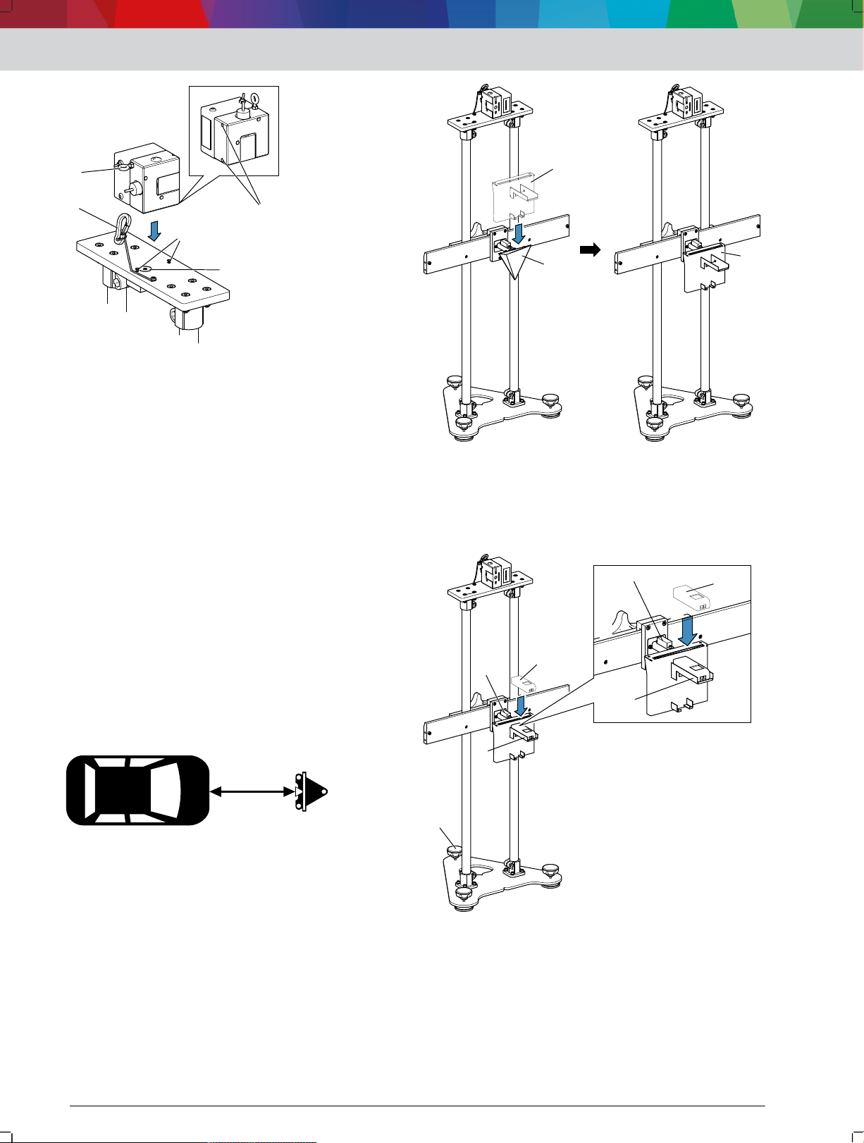
11
22
3
4
5
10: Закрепване на линейния лазер
1
2
1
1
2
3
4
1
2
3
(1) Позициониращи щифтове
(2) Кондукторни втулки
(3) Магнит
(4) Спирачно въже
(5) Зегеров пръстен
Позиционирайте линейния лазер с кондукторните
3.
втулки върху позициониращите щифтове.
Линейният лазер се привлича от магнита 4512003-17_shd.svg 10
(3) във захващащия елемент.
Позициониращите щифтове са в кондукторните
втулки на линейния лазер.
Линейният лазер стои неподвижно върху
захващащия елемент и не може да се усуче.
Закрепете спирачното въже 4512003-17_shd.svg 10 (4) на
4.
захващащия елемент за линейния лазер на
зегеровия пръстен 4512003-17_shd.svg 10 (5) на линейния лазер.
Линейният лазер е обезопасен срещу падане.
---Сепаратор---
Обслужване | SCT 815 | 27 | bg
12: Позициониране на захващащия елемент за лазерния
далекомер
(1) Захващащ елемент за лазерния далекомер
(2) Тройна призма
Поставете лазерния далекомер 4512003-09_shd.svg 13 (1) в
5.
хоризонталната подложка 4512003-09_shd.svg 13 (2).
4.3 Настройване на разстоянието от
SCT 815 до превозното средство
Разстоянието от SCT 815 до превозното средство е
посочено в съответната кратка инструкция.
Разстоянието, специфично за превозното средство,
се намира в колоната със следната пиктограма.
11: Пиктограма за разстоянието от SCT 815 до превозното
средство
1. Използвайте съответната кратка инструкция.
2. Отчетете разстоянието от SCT 815 до съответното
превозно средство.
3. Повдигнете SCT 815 за направляващите щанги и
позиционирайте на око в центъра на превозното
средство на посоченото разстояние.
4. Позиционирайте захващащия елемент за
лазерния далекомер 4512003-08_shd.svg 12 (1) върху тройната
призма 4512003-08_shd.svg 12 (2).
13: Поставяне на лазерния далекомер
(1) Лазерен далекомер
(2) Хоризонтална подложка
(3) Либела на тройната призма
(4) Регулируем крак
6. SCT 815 да се нивелира според либелата на
тройната призма 4512003-09_shd.svg 13 (3) с регулируемия край
4512003-09_shd.svg 13 (4).
1 689 989 362 | 2018-08-01Robert Bosch GmbH
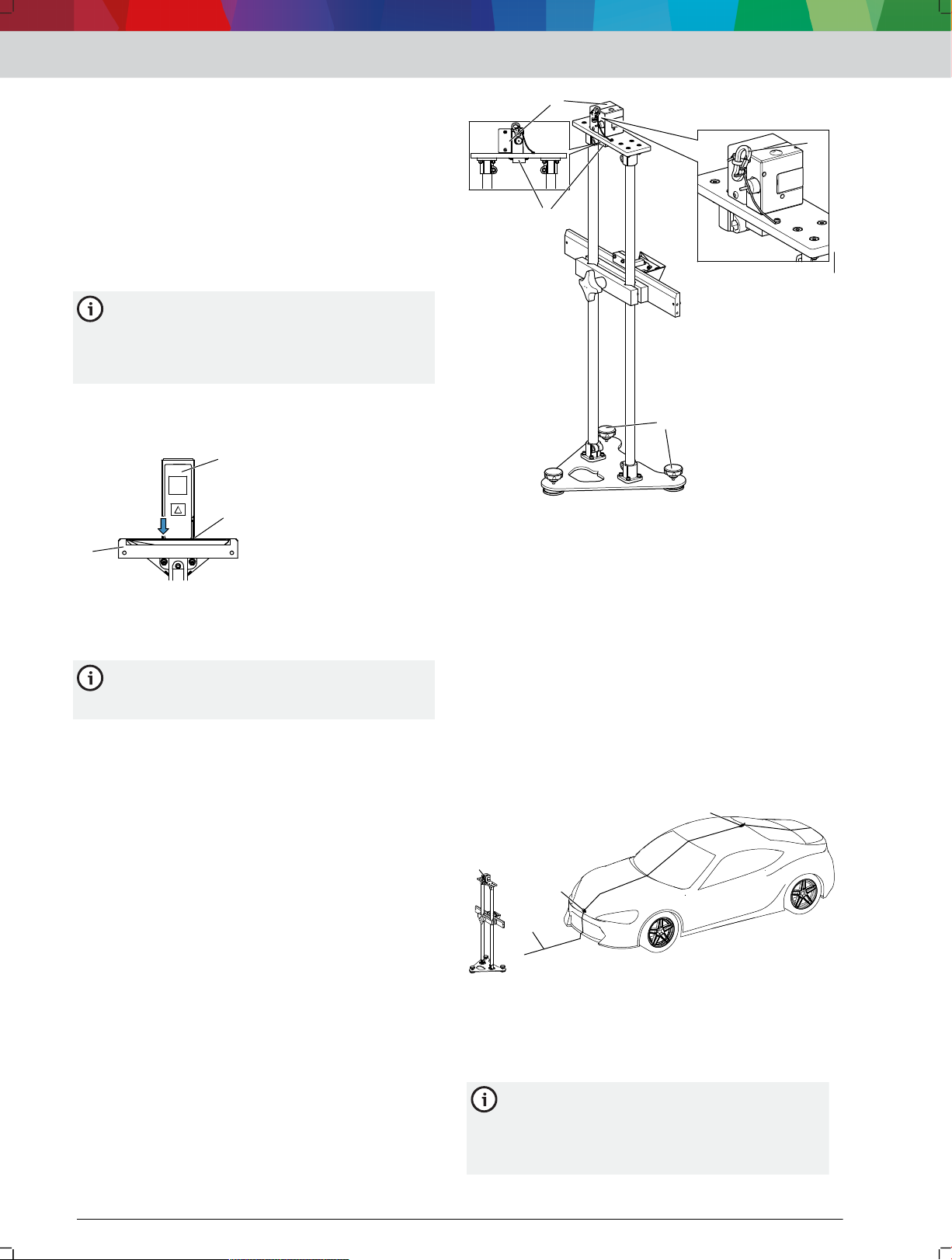
1
2
3
11
22
33
4
1
2
3
4
bg | 28 | SCT 815 | Обслужване
ПРЕДУПРЕЖДЕНИЕ - Тежки наранявания на очите,
причинени от лазерния лъч.
7. Никога не гледайте директно в лазерния източник.
8. За функционален контрол дръжте предмет пред
изходната точка на лазерния далекомер.
9. Включете лазерния далекомер.
10. Настройте височината на тройната призма така, че
лазерната точка да маркира средата на буферната
греда.
Лазерният далекомер показва текущото
разстояние от SCT 815 до буферната греда.
Лазерният далекомер постоянно измерва
разстоянието. При промяна на позицията от
SCT 815 на дисплея на лазерния далекомер
се показва ново разстояние до буферната
греда.
Уверете се, че лазерният ограничител с
11.
подложката назад лежи на хоризонталната
подложка.
14: Лазерен далекомер на задния ограничител
(1) Лазерен далекомер
(2) Заден ограничител на хоризонталната подложка
(3) Захващащ елемент за лазерния далекомер
Ще се появят грешки при измерването, ако
лазерният далекомер не лежи с ограничителя
назад в хоризонталната подложка.
Позиционирайте SCT 815 с помощта на лазерния
12.
далекомер точни в указаното разстояние пред
превозното средство.
SCT 815 е правилно позициониран, ако
данните върху лазерния далекомер съвпадат с
данните в кратката инструкция.
---Сепаратор---
4.4 SCT 815 да се подравни спрямо
надлъжната средна равнина на
превозното средство
Закрепете линейния лазер 4512003-13_shd.svg 15 (1) на
1.
захващащия елемент за линейния лазер и
обезопасете със спирачното въже 4512003-13_shd.svg 15 (4).
2. Нивелирайте SCT 815 спрямо либелата на
захващащия елемент на линейния лазер 4512003-13_shd.svg 15 (2) с
регулируемите крака 4512003-13_shd.svg 15 (3).
15: Ориентиране на SCT 815
(1) Линеен лазер
(2) Либела на захващащия елемент за линейния лазер
(3) Регулируеми крака
(4) Спирачно въже
ПРЕДУПРЕЖДЕНИЕ - Тежки наранявания на очите,
причинени от лазерния лъч.
Никога не гледайте директно в лазерния източник.
3.
За функционален контрол дръжте предмет пред
4.
изходната точка на линейния лазер.
Включете линейния лазер.
5.
Лазерната линия минава през превозното
средство.
Подравнете SCT 815 така, че емблемата на
6.
производителя на предното превозно средство и
антената да са маркирани чрез лазерната линия
4512003-14_shd.svg 16 (2).
16: Подравняване на SCT 815 спрямо надлъжната средна
равнина на превозното средство
(1) Линеен лазер
(2) Прожектирана лазерна линия
(3) Емблема на производителя
(4) Антена
Според превозното средство могат да се
използват и други фиксирани точки, за да
подравните SCT 815 с линейния лазер
спрямо надлъжната средна равнина на
превозното средство.
1 689 989 362 | 2018-08-01 Robert Bosch GmbH
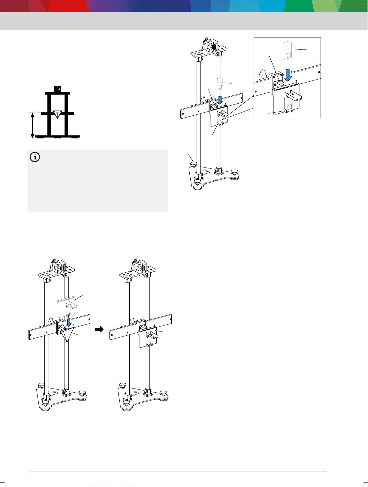
---Сепаратор---
1
2
1
1
2
3
4
1
3
2
4.5 Настройване на височината на
тройната призма
Височината на тройната призма е посочена в
кратката инструкция. Височината, специфична за
превозното средство, се намира в колоната със
следната пиктограма.
17: Пиктограма за височината на тройната призма
Височината, специфична за превозното
средство, в кратката инструкция е валидна,
ако превозното средство е на същата
повърхност като SCT 815. Ако превозното
средство е върху подемна платформа или
нивелираща повърхност, вдигането трябва да
се измери. Измерената височина трябва да се
добави към височината, специфична за
превозното средство, от кратката инструкция.
Използвайте съответната кратка инструкция.
1.
Отчетете височината на тройната призма до
2.
съответното превозно средство.
Позиционирайте захващащия елемент за
3.
лазерния далекомер 4512003-08_shd(2).svg 18 (1) върху тройната
призма 4512003-08_shd(2).svg 18 (2).
Обслужване | SCT 815 | 29 | bg
19: Поставяне на лазерния далекомер
(1) Лазерен далекомер
(2) Вертикална поставка
(3) Либела на тройната призма
(4) Регулируем крак
SCT 815 да се нивелира според либелата на
5.
тройната призма 4512003-11_shd.svg 19 (3) с регулируемия край
4512003-11_shd.svg 19 (4).
ПРЕДУПРЕЖДЕНИЕ - Тежки наранявания на очите,
причинени от лазерния лъч.
Никога не гледайте директно в лазерния източник.
6.
За функционален контрол дръжте предмет пред
7.
изходната точка на лазерния далекомер.
Включете лазерния далекомер.
8.
Лазерният далекомер показва текущото
отстояние на тройната призма от пода.
ВНИМАНИЕ - Опасност от приклещване при
настройване на височината на тройната призма.
Не поставяйте пръстите си между затегателните
9.
скоби и направляващите тръби.
Развивайте винта с назъбена глава 4512003-12_shd.svg 20 (1) на
10.
затегателната скоба, докато тройната призма
може да се настрои по височина.
18: Позициониране на захващащия елемент за лазерния
(1) Захващащ елемент за лазерния далекомер
(2) Тройна призма
4. Поставете лазерния далекомер 4512003-11_shd.svg 19 (1) във
далекомер
вертикалната подложка 4512003-11_shd.svg 19 (2).
1 689 989 362 | 2018-08-01Robert Bosch GmbH
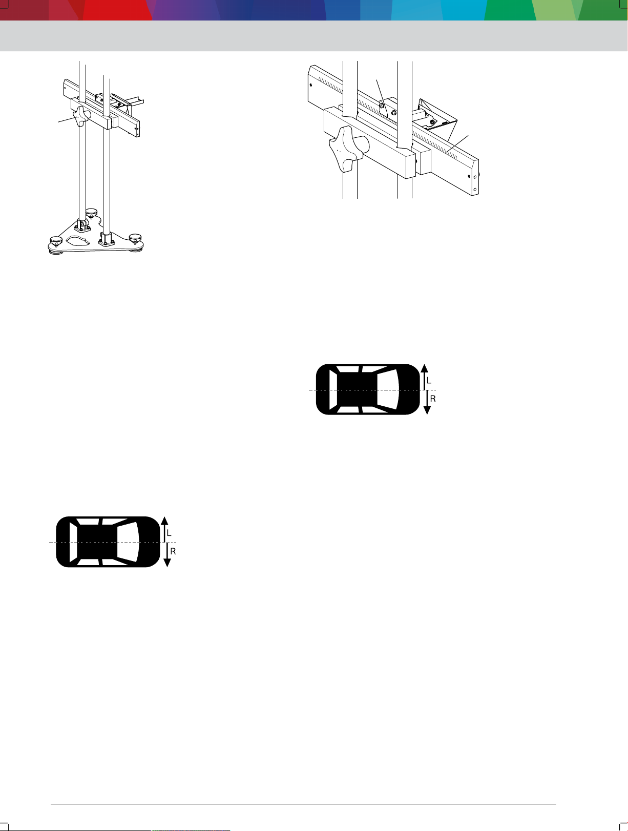
1
1
2
bg | 30 | SCT 815 | Обслужване
20: Настройване на височината на тройната призма
(1) Винт с назъбена глава
11.
Позиционирайте тройната плазма с помощта на
лазерния далекомер точно на височината,
специфична за превозното средство.
При вдигане на превозното средство с
—
помощта на подемна платформа или
нивелираща повърхност измерете вдигането и
го добавете към височината, специфична за
превозното средство.
Фиксирайте затегателната скоба с винта с
12.
назъбена глава.
---Сепаратор---
22: Настройване на изместване до 25
(1) Линия на затегателната скоба
(2) Стрелка върху тройната призма за точна настройка на
изместването
---Сепаратор---
4.7 Настройте изместване (от 25cm)
спрямо надлъжната средна равнина
на превозното средство
Изместването на тройната призма спрямо
надлъжната средна равнина е посочено в
съответната кратка инструкция. Изместването,
специфично за превозното средство, се намира в
колоната със следната пиктограма.
4.6 Настройте изместването (до 25cm)
спрямо надлъжната средна равнина
на превозното средство
23: Пиктограма за изместването на тройната призма
SCT 815 трябва да е подравнен спрямо надлъжната
средна равнина на превозното средство.
Изместването на тройната призма спрямо
Използвайте съответната кратка инструкция.
надлъжната средна равнина е посочено в
съответната кратка инструкция. Изместването,
специфично за превозното средство, се намира в
колоната със следната пиктограма.
1.
Отчетете изместването от SCT 815 до съответното
2.
превозно средство.
ПРЕДУПРЕЖДЕНИЕ - Тежки наранявания на очите,
причинени от лазерния лъч.
Никога не гледайте директно в лазерния източник.
3.
За функционален контрол дръжте предмет пред
4.
изходната точка на линейния лазер.
SCT 815 да се подравни спрямо надлъжната
5.
21: Пиктограма за изместването на тройната призма
SCT 815 трябва да е подравнен спрямо надлъжната
средна равнина на превозното средство.
1. Използвайте съответната кратка инструкция.
2. Отчетете изместването от SCT 815 до съответното
превозно средство.
3. Настройте изместването на тройната призма с
помощта на линиите на затегателната скоба 4512003-15_shd.svg 22
(1).
средна равнина на превозното средство. SCT 815 zur Fahrzeug-Längsmittelebene ausrichten 28
"SCT 815 да се подравни спрямо надлъжната средна
равнина на превозното средство"
6. Нарисувайте две помощни линии 4512003-16_shd.svg 24 (2) с
дължината на посоченото изместване под прав
ъгъл спрямо прожектираната лазерна линия 4512003-16_shd.svg 24
(1).
7.
Нарисувайте паралелна линия до прожектираната
лазерна линия с помощта на две помощни линии.
8. SCT 815 да се премести, докато прожектираната
лазерна линия на линейния лазер премине върху
паралелно начертаната линия.
1 689 989 362 | 2018-08-01 Robert Bosch GmbH
 Loading...