

Bosch Safecom SC720, Safecom SC820 Operation And Installation Manual
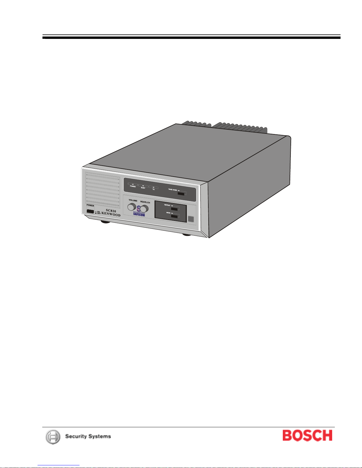
SAFECOM SC720/SC820 Data Repeater
Operation and Installation Guide

FCC Statement
Federal regulations require a station license for each radio installation be obtained by the equipment owner. The
licensee is responsible for ensuring transmitter power, frequency, and deviation are within the limits permitted by
the station license.
Transmitter adjustments may be performed only by a licensed technician holding an FCC first, second or general
class commercial radiotelephone operator’s license. There is no license required to install or operate the radio.
FCC ID: IVN 3470
90007-201C Page 2 © 2004 Bosch Security Systems
SC720/SC820 Operation and Installation Guide

SC720/SC820
Contents
1.0 Introduction.......................................................................................5
1.1 Manual Organization......................................................................................................................................... 5
1.2 Documentation Conventions............................................................................................................................. 5
1.2.1 Type Styles Used in this Manual......................................................................................................................5
1.2.2 Tips, Important Notes, Cautions and Warnings................................................................................................ 5
1.3 Listings and Standards .....................................................................................................................................6
1.3.1 UL Listing ....................................................................................................................................................6
1.3.2 NFPA Standards............................................................................................................................................... 6
2.0 Overview............................................................................................7
2.1 SAFECOM Overview........................................................................................................................................7
2.2 Data Repeater Communications....................................................................................................................... 8
2.3 SC720/SC820 Data Repeater Overview .......................................................................................................... 8
2.4 System Specifications....................................................................................................................................... 9
2.4.1 General ....................................................................................................................................................9
2.4.2 Receiver ....................................................................................................................................................9
2.4.3 Transmit .................................................................................................................................................... 9
3.0 Installation.......................................................................................10
3.1 Requirements..................................................................................................................................................10
3.1.1 Earth Ground.................................................................................................................................................. 10
3.1.2 Wiring and Cable............................................................................................................................................ 10
3.1.3 Power ..................................................................................................................................................10
3.1.4 Antenna Location............................................................................................................................................ 11
3.1.5 Surge Protection.............................................................................................................................................11
3.1.6 Data Repeater Location.................................................................................................................................. 11
3.2 Connecting Cables to the SC720/SC820 .......................................................................................................12
4.0 Operation.........................................................................................13
4.1 Controls and Indicators...................................................................................................................................13
4.2 Panel Control Settings for Data Repeater Communications...........................................................................15
4.3 Procedures ..................................................................................................................................................15
4.3.1 Transmit a Test Data Pattern..........................................................................................................................15
4.3.2 Audibly Monitor Only SAFECOM Messages.................................................................................................. 15
4.3.3 Audibly Monitor all Radio Activity....................................................................................................................15
5.0 System Adjustments ......................................................................17
5.1 SC720/SC820 System Adjustments...............................................................................................................17
5.2 Removing/reinstalling the SC720/SC820 and DK1000 Access Covers .........................................................17
5.2.1 Removing the access covers.......................................................................................................................... 17
5.2.2 Reinstalling the access covers.......................................................................................................................17
5.3 Settings............................................................................................18
5.3.1 The Squelch Threshold...................................................................................................................................18
5.3.2 Setting the Modulation Deviation....................................................................................................................18
5.3.3 Setting the Hanging Time...............................................................................................................................19
5.3.4 Output Power.................................................................................................................................................. 19
5.3.5 Setting the Decode Characters.......................................................................................................................19
5.4 Setup for an Addressable Data Repeater.......................................................................................................20
5.4.1 Setting the Address Codes.............................................................................................................................20
5.5 Summary of IP1 Header Pins.........................................................................................................................20
5.6 DK1000 Default Settings ................................................................................................................................ 21
© 2004 Bosch Security Systems Page 3 90007-201C
SC720/SC820 Operation and Installation Guide

SC720/SC820
Contents
Figures
Figure 1: Data Repeater Operations ......................................................................................................................................8
Figure 2: SC720/SC820 Rear Panel ....................................................................................................................................12
Figure 3: SC720/SC820 Front Panel....................................................................................................................................13
Figure 4: System Adjustments..............................................................................................................................................18
Tables
Table 1: SC720/SC820 Operation and Installation Guide Manual Organization....................................................................5
Table 2: UL Listings................................................................................................................................................................6
Table 3: NFPA Standards.......................................................................................................................................................6
Table 4: SC720/SC820 Rear Panel Connectors..................................................................................................................12
Table 5: SC720/SC820 Front Panel Items...........................................................................................................................14
Table 6: SC720/SC820 Decode Character = 3 for Primary SC720/SC820..........................................................................20
Table 7: SC720/SC820 Decode Character = 3 for Backup SC720/SC820..........................................................................20
Table 8: DK1000 Controller Board Pin Settings...................................................................................................................20
Table 9: IP1 Header Pins......................................................................................................................................................20
Table 10: DK1000 Default Settings ......................................................................................................................................21
90007-201C Page 4 © 2004 Bosch Security Systems
SC720/SC820 Operation and Installation Guide

1.0 Introduction
1.1 Manual Organization
This manual is divided into 6 sections. A summary of each section and appendix is detailed in the table below.
Section Description
1 Introduction
2 Overview
3 Installation
4 Operation
5 System Adjustments
6 Troubleshooting
Table 1: SC720/SC820 Operation and Installation Guide Manual Organization
1.2 Documentation Conventions
These conventions are intended to call out important features, items, notes, cautions, and warnings that the
reader should be aware of in reading this document.
1.2.1 Type Styles Used in this Manual
To help identify important items in the text, the following type styles are used:
Bold text
Bold Italicized
Italicized text
Courier Text
[CAPITALIZED TEXT] Text like this is used to indicate to the user that a specific key should be pressed.
Italicized Text
1.2.2 Tips, Important Notes, Cautions and Warnings
Throughout this document, helpful tips, important notes, cautions and warnings will be presented for the reader
to keep in mind. These appear different from the rest of the text as follows:
Important Notes - should be heeded for successful operation and programming. Also tips and
shortcuts may be included here.
usually indicates selections that you may use while programming your panel. It may
also indicate an important fact that should be noted.
used to denote notes, cautions and/or warnings
Is used to reference the user to another part of this manual or another manual
entirely. It is also used to symbolize names for records that the user will create.
Text that appears like this indicates what may appear on the D5200 Programmer
display, command center/keypad or internal printer.
Example: …press the [ESC] key…
Text that appears like this indicates what would be seen in the D5200 Programmer’s
Display. It is used as a section heading and screen example. Shaded boxes indicate
programmer prompts that are only available when Custom or View Events are
selected. (Used only in the Program Entry Guide documents).
SC720/SC820
Introduction
Caution - These caution the operator that physical damage to the program and/or equipment may
occur.
Warning - These warn of the possibility of physical damage to the operator, program and/or
equipment.
© 2004 Bosch Security Systems Page 5 90007-201C
SC720/SC820 Operation and Installation Guide

SC720/SC820
Introduction
1.3 Listings and Standards
1.3.1 UL Listing
The SAFECOM SC720/SC820 Data Repeater system is Listed by Underwriters Laboratories (UL) as follows:
Application and Category Listing
Central Station Burglar Alarm Units
• COMMERCIAL BURGLARY - AA” Rating
Central Station “Police Connect” Mercantile
• “AA” Rating
Control Units for Fire Protective Signaling Systems
• “COMMERCIAL FIRE” Rating
Proprietary Burglar Alarm System Units
• PROPRIETARY BURGLARY - AA” Rating
Household Burglar Alarm Units
• “RESIDENTIAL BURGLAR ALARM” Application
Household Fire Warning System Units
• “RESIDENTIAL FIRE “ Application
Process Management Systems
• Service: “Non-Critical Applications”
1.3.2 NFPA Standards
The SAFECOM SC720/SC820 Data Repeater system meets the following NFPA Standards:
Application Standard No.
Central Station Signaling Systems NFPA No. 71
Auxiliary Protective Signaling Systems NFPA No. 72B
Remote Station Protective Signaling Systems NFPA No. 72C
Proprietary Protective Signaling Systems NFPA No. 72D
In accordance with NFPA No. 71 and UL Requirements the maximum number of subscriber control units
(SAFECOM Remote Communications Panels) that a single SAFECOM SC720/SC820 Data Repeater can
monitor for Fire and/or Burglary Applications is “512.”
If the number of subscriber control units exceeds 512, a second SC720/SC820 Data Repeater will be required to
monitor and control the additional units.
If the SAFECOM system is configured with more than one (1) SC720/SC820 Data Repeater, the number of
subscriber control units that can be monitored and controlled is UNLIMITED.
Standard
UL 1610
UL 365
UL 864
UL 1076
UL 1023
UL 985
UL 864
Table 2: UL Listings
Table 3: NFPA Standards
90007-201C Page 6 © 2004 Bosch Security Systems
SC720/SC820 Operation and Installation Guide

SC720/SC820
Overview
2.0 Overview
2.1 SAFECOM Overview
SAFECOM is a long-range telemetry communications system for monitoring remote security alarm panels which
are located at a customer site. The SAFECOM system utilizes specially designed telemetry transmitters and
receivers to provide a secure and reliable radio communications link between remote alarm control panels and a
Central Monitoring Station. The information provided to the Central Station allows security personnel or local
authorities to respond immediately and appropriately to all alarm events detected at the customer site.
The SAFECOM system is listed by Underwriters Laboratories (UL) as an
reporting, RADIO as PRIMARY, of Burglary and Fire Alarm events and information.
The SC9000 Receiver acts as the nerve center of the SAFECOM System. The SC9000 Receiver uses the
SAFECOM ST1000 receiver software for system control and processing. The SC9000 communicates with
Remotes via the RF2000 Radio Modem. Selected system events are permanently recorded on a Micronics dot
matrix printer.
A Radio Communicator is a SAFECOM SC4000 Communications Panel which is located at a customer site;
commercial or residential. The Remote intercepts ALL of the Alarm Panel Digital Messages from the Digital
Alarm Communicator (DAC or DIALER), digitally encodes it, and performs a full data transfer via a RADIO
communications link to the Base Station’s SC9000 Receiver as the PRIMARY routing.
The digital data is processed by the SC9000 Receiver with a virtual instantaneous transfer of alarm information
to a Central Monitoring Station’s Automation software. Normal routing of the Digital Alarm Messages is via a
RADIO communications link between a Remote and the SC9000 Receiver; then to an Automation software via
an RS232 interface cable.
The SC9000 Receiver can supervise, monitor, and control up to 2,500 Remotes through two-way RADIO
telemetry communication in the redundant configuration. The receipt of each message or supervisory poll that is
transmitted, is validated by the receiving site. The receiving site will transmit an acknowledge message in
response.
Supervisory polling is performed by the SC9000 Receiver for each Remote to verify two-way RADIO telemetry
communications and the operational condition of the Remote. The polling interval is individually programmable
for each Remote. The SC9000 Receiver can monitor 240 unique Alarm Panel Event Codes from each Remote.
The Remote can also monitor the Normal/Open/Short status for four (4) Auxiliary Inputs. These input lines allow
End-Of-Line (EOL) supervisory loop status monitoring of four auxiliary devices. Any change of status to the
inputs is immediately reported to the SC9000 Receiver or routed to initiate fault follower behavior for the Auxiliary
Output relays. The box tamper switch is permanently connected to an auxiliary input line for continuous
monitoring of panel door open/closure status.
There are also four (4) 2-position contact relay controlled Auxiliary Outputs. The Base Station operator can
remotely control the On/Off status of an auxiliary device by sending RADIO commands, from the SC9000
Receiver, to Enable or Disable the output relays. The Remotes may also be programmed to automatically Enable
or Disable the output relays in response to an Auxiliary Input or Remote system Failure condition.
The SAFECOM system functions strictly in a supervisory capacity when interfaced with an existing alarm system.
The Remotes are intercept/delivery systems which are designed for easy installation and interface with an alarm
system; just connect the alarm panel telephone output cable to the Remote phone terminals. NO modifications to
the existing alarm system are required! The normal operation of the existing alarm panel and security system is
NOT affected in any way. The existing detectors and initiating circuits still report the status of items directly to the
alarm panel.
The RF2000 and Remotes are normally configured to transmit and receive (Tx/Rx) in the 450-470 MHz UHF
Radio Frequency (ElF) range. Additional frequency Ranges are available upon request. Nominal reception range
is dependent on the extent of environmental effects, i.e. propagation, and the proximity of the transmitter/receiver
to dense foliage and structures. The SC9000 radio Comm Port can drive a single RF channel or with the
installation of a SAFECOM 4 or 8 port Expander Board it can drive from 1 to 8 independent RF channels.
To ensure alarm events are reported by the Alarm Panel Dialer, when it seizes the communications line and
starts dialing the programmed phone number, all SAFECOM Remotes are configured with a FALLBACK feature.
In the event of a Remote RADIO, hardware, software, or total power failure the digital alarm messages are
automatically routed via a telephone communications line to a digital receiver; then to the Automation software
via an RS232 interface cable. This provides a life safety BACKUP communications link for routing of Alarm Panel
messages to the Central Monitoring Station.
The SAFECOM IT1500 Installation/Sales Tool tests for a standardized signal level, at the customer site, from the
RF2000 Radio Modem. Through this testing, by a Sales or Service Representative, the potential for valid twoway RADIO communications can be confirmed for a Remote and the SC9000 Receiver prior to the installation of
a SAFECOM system.
SC720/SC820 Operation and Installation Guide
© 2004 Bosch Security Systems Page 7 90007-201C
“AA”
rated security device for telemetry
SC720/SC820
Overview
2.2 Data Repeater Communications
A Data Repeater is a well situated automatic re-transmission station used to significantly extend the effective
RADIO communications range of a transceiver. The Data Repeater station consists of a receiver, control
circuitry, interconnect circuitry, a transmitter, power supplies, an optional duplexer and at least one antenna. The
SAFECOM Data Repeater is a FULL DUPLEX FM RADIO repeater. The repeater receives the RADIO signal on
one frequency, demodulates it, processes it, remodulates it, applies it to the input of the repeater transmitter, and
re-transmits it on a second frequency. A Full Duplex system can transmit and receive at the same time
(simultaneously).
2.3 SC720/SC820 Data Repeater Overview
The ability of the SC9000 Receiver to monitor Radio Communicator Panels, which are geographically separated
by great distances, is significantly improved by telemetry range extension through the use of the SAFECOM
SC720/SC820 Data Repeater.
Note: The SC720/SC820 is intended for single (one) customer operating company service.
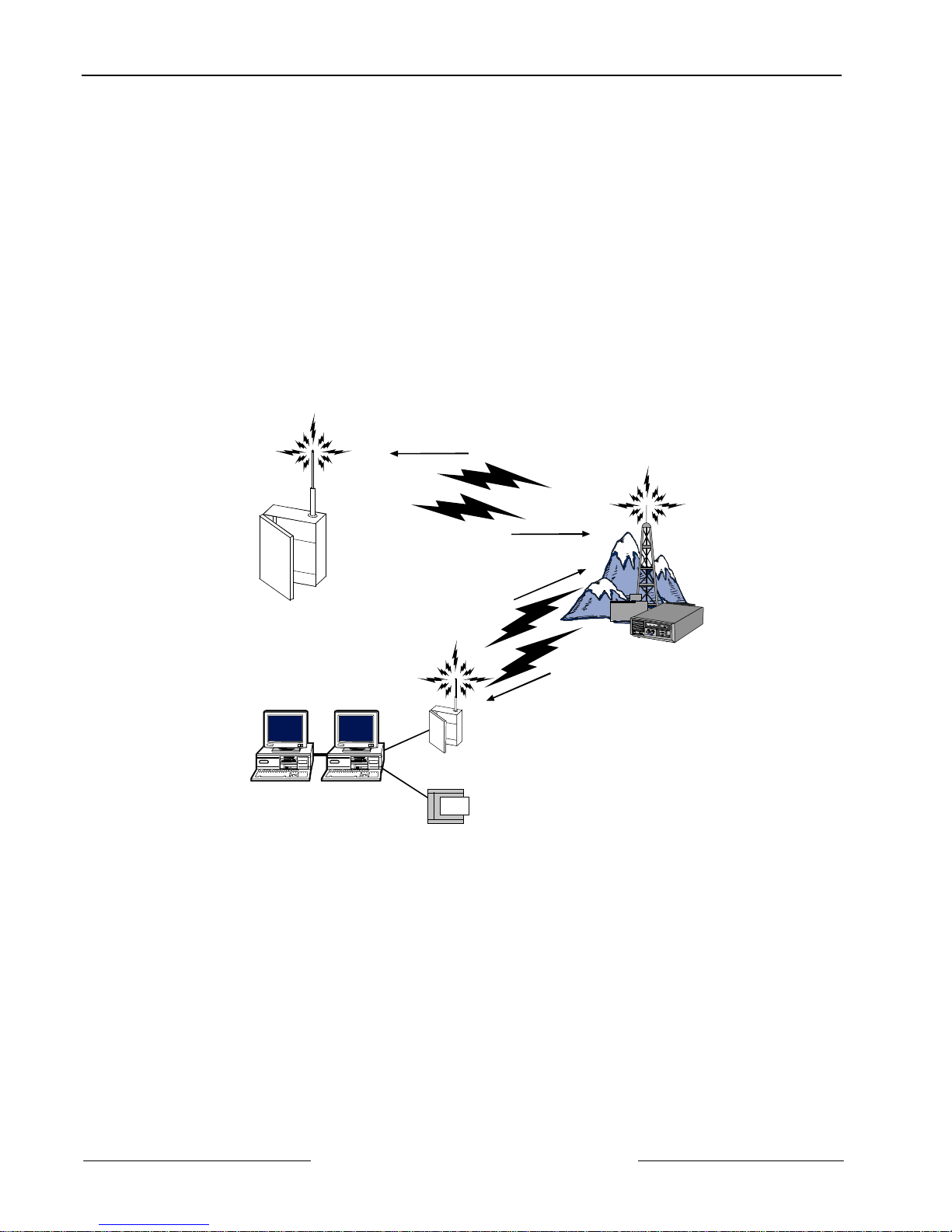
The SAFECOM SC720/SC820 Data Repeater is a Full Duplex, real-time, digital data repeater system. It
simultaneously receives (FREQ X) and transmits (FREQ Y) on two separate RADIO frequencies, in the UHF
frequency spectrum. See Figure 1.
SC4000
Base Station
AUTOMATION
SOFTWARE
Customer Site
RF2000
SC9000
RECEIVER
FREQY
FREQX
FREQX
FREQ Y
PRINTER
Repeater Site
SC820
Figure 1: Data Repeater Operations
The SC720/SC820 is based on a Kenwood model #TKR-820 platform. The existing repeater signaling unit has
been replaced by the SAFECOM DK1000 Controller Board. The incorporation of the DK1 000 provides the realtime digital data repeater capability to the system.
Note: The SC720/SC820 can NOT be used as a transceiver for voice, voice repeater, or store and forward
digipeater communications.
The SC720/SC820 has an enhanced feature to limit identifying-carrier detect (CD) to SAFECOM RADIO signals
transmitted by the RF2000 Radio Modem or Remote comm panels. The DK1000 controller board will look at the
group of message bytes received when it detects a RADIO carrier (Carrier Detect - CD). If the CD message
groups do NOT contain the proper message validation, the RADIO signal will be ignored by the SC720/SC820.
ONLY messages with the proper validation byte messages will be processed by the DK1000 controller board for
data repeater RADIO communications.
The SC720/SC820 power output is adjustable from a minimum of 2 watts to a maximum of 25 watts. The
SC720/SC820 can be configured with a duplexer to allow the transmitter and receiver to connect to the same
antenna. With a duplexer installed, the maximum power output is reduced.
90007-201C Page 8 © 2004 Bosch Security Systems
SC720/SC820 Operation and Installation Guide
 Loading...