

Bosch RT30A, RT960A Instruction Manual
RT30A & RT960A
Instruction Manual
EN High Density Video
Cassette Recorder
High Density Video Cassette Recorder | Instruction Manual | Important Safeguards
Bosch Security Systems | 26 Feb 2003 | Draft
EN
|
1
Important Safeguards
1. Read these instructions.
2. Keep these instructions.
3. Comply with all warnings.
4. Follow all instructions.
5. Do not use this equipment near water.
6. Clean only with dry cloth.
7. Do not block any ventilation openings. Install in
accordance with the manufacturer’s instructions.
8. Do not install near any heat sources such as
radiators, heat registers, stoves, or other equipment
(including amplifiers) that produce heat.
9. Note to CCTV System Installer. This reminder is
provided to call the CCTV System Installer’s
attention to Article 820-40 of the NEC that
provides guidelines for proper grounding and, in
particular, specifies that the cable ground shall be
connected to the grounding system of the building,
as close to the point of cable entry as practical.
10. CAUTION: To prevent electric shock, match wide
blade of plug to wide slot, fully insert.
11. Do not defeat the safety purpose of the polarized or
grounding-type plug. A polarized plug has two
blades with one wider than the other. A grounding
type plug has two blades and a third grounding
prong. Both the wide blade and the third prong are
provided for your safety. If the provided plug does
not fit into your outlet, consult an electrician for
replacement of the obsolete outlet.
12. Protect the power cord from being walked on or
pinched particularly at plugs, convenience
receptacles, and the point where they exit from the
equipment.
13. Only use attachments/accessories specified by the
manufacturer.
14. Unplug this equipment during lightning storms or
when unused for long periods of time.
15. Refer all servicing to qualified service personnel.
Servicing is required when the equipment has been
damaged in any way, such as power-supply cord or
plug is damaged, liquid has been spilled or objects
have fallen into the equipment, the equipment has
been exposed to rain or moisture, does not operate
normally, or has been dropped.
16. WARNING: To reduce the risk of fire or electric
shock, do not expose this equipment to rain or
moisture.
17. The equipment shall not be exposed to dripping or
splashing and that no objects filled with liquids,
such as vases, shall be placed on the equipment.
18. The top cover of the recorder should only be
removed by qualified maintenance and service
personnel.
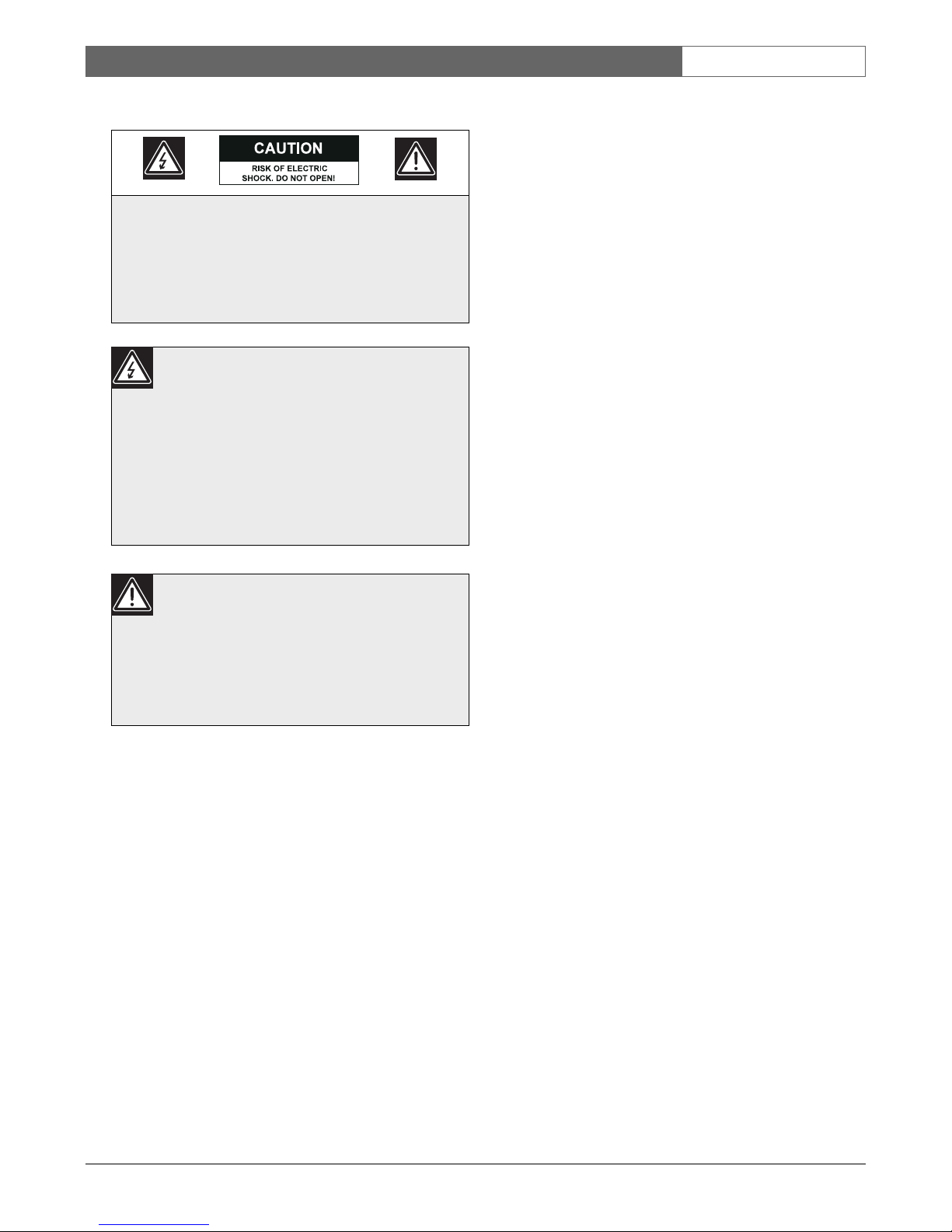
CAUTION: TO REDUCE THE RISK OF
ELECTRIC SHOCK, DO NOT REMOVE COVER
(OR BACK). NO USER SERVICEABLE PARTS
INSIDE. REFER SERVING TO QUALIFIED
SERVICE PERSONNEL.
The lightning flash with an arrowhead
symbol, within an equilateral triangle, is
intended to alert the user to the
presence of uninsulated “dangerous
voltage” within the product’s enclosure
that may be of sufficient magnitude to
constitute a risk of electric shock to
persons.
The exclamation point within an
equilateral triangle is intended to alert
the user to presence of important
operating and maintenance (servicing)
instructions in the literature
accompanying the appliance.

High Density Video Cassette Recorder | Instruction Manual | FCC Information
Bosch Security Systems | 26 Feb 2003 | Draft
EN
|
2
Ventilation
19. Keep ventilation openings free to avoid the
recorder for overheating.
20. Do not place the recorder in the immediate vicinity
of a heating source.
21. Do not install this equipment in a confined space
such as a bookcase or similar unit.
22. Keep distance about 10cm minimum from the wall
when installed.
Cleaning
20. You can clean the recorder with a moist fluff-free
cloth or shammy leather cloth.
Disposal
21. This recorder contains a battery. Do not dispose of
the battery with other solid waste. The battery is
located inside the recorder. To remove the battery,
remove the recorder cover by unscrewing the 4
crosshead screws, remove the cover, then break off
the battery from the circuit board.
CAUTION: Danger of explosion if batteries
are incorrectly replaced. Replace only with
the same or equivalent type.
Remark: Bosch has a strong commitment towards the
environment. This recorder has been designed to
respect the environment as much as possible.
FCC Information
This equipment has been tested and found to comply
with the limits for a Class B digital device, pursuant to
part 15 of the FCC Rules. These limits are designed to
provide reasonable protection against harmful
interference in a residential installation. This
equipment generates, uses and can radiate radio
frequency energy and, if not installed and used in
accordance with the instructions, may cause harmful
interference to radio communications. However, there
is no guarantee that interference will not occur in a
particular installation. If this equipment does cause
harmful interference to radio or television reception,
which can be determined by turning the equipment off
and on, the user is encouraged to try to correct the
interference by one or more of the following measures:
• Reorient or relocate the receiving antenna.
• Increase the separation between the equipment and
receiver.
• Connect the equipment into an outlet on a circuit
different from that to which the receiver is
connected.
• Consult the dealer or an experienced radio/ TV
technician for help.
Note:
Any change or modification not expressly approved
by Bosch of the equipment authorization could void
the user's authority to operate the equipment.
For additional information or to speak to a
representative, please contact the Bosch Security
Systems location nearest you or visit our web site at
www.boschsecuritysystems.com.
(See: Your Guide To Observation)
WARNING:This device is intended for use in
public areas only. Surreptitious recording of
oral communications is strictly prohibited by
U.S. Federal law

High Density Video Cassette Recorder | Instruction Manual | Contents
Bosch Security Systems | 26 Feb 2003 | Draft
EN
|
3
Table of Contents
Important Safeguards . . . . . . . . . . . . . . . . . . . . . . . . . . . . . . . . . . . . . . . . . . . . . . . . . . . . . . . . . . . . . . . . . .1
FCC Information . . . . . . . . . . . . . . . . . . . . . . . . . . . . . . . . . . . . . . . . . . . . . . . . . . . . . . . . . . . . . . . . . . . . .2
1 UNPACKING . . . . . . . . . . . . . . . . . . . . . . . . . . . . . . . . . . . . . . . . . . . . . . . . . . . . . . . . . . . . . . . . . .4
2 SERVICE . . . . . . . . . . . . . . . . . . . . . . . . . . . . . . . . . . . . . . . . . . . . . . . . . . . . . . . . . . . . . . . . . . . . .4
3 DESCRIPTION . . . . . . . . . . . . . . . . . . . . . . . . . . . . . . . . . . . . . . . . . . . . . . . . . . . . . . . . . . . . . . . .4
4 CONTROLS . . . . . . . . . . . . . . . . . . . . . . . . . . . . . . . . . . . . . . . . . . . . . . . . . . . . . . . . . . . . . . . . . . .5
4.1 Controls and Functions . . . . . . . . . . . . . . . . . . . . . . . . . . . . . . . . . . . . . . . . . . . . . . . . . . . . . . . . . . .5
5 INSTALLATION . . . . . . . . . . . . . . . . . . . . . . . . . . . . . . . . . . . . . . . . . . . . . . . . . . . . . . . . . . . . . . .9
5.1 Video Connection (Fig 4, Item 3) . . . . . . . . . . . . . . . . . . . . . . . . . . . . . . . . . . . . . . . . . . . . . . . . . . .9
5.2 Audio Connection (Fig 4, Item 2) . . . . . . . . . . . . . . . . . . . . . . . . . . . . . . . . . . . . . . . . . . . . . . . . . . .9
5.3 Using the 9-pin Terminals (Fig 4, Item 4) . . . . . . . . . . . . . . . . . . . . . . . . . . . . . . . . . . . . . . . . . . . . .9
5.4 VCR Setup . . . . . . . . . . . . . . . . . . . . . . . . . . . . . . . . . . . . . . . . . . . . . . . . . . . . . . . . . . . . . . . . . . . .10
5.5 Video Cassette Tapes . . . . . . . . . . . . . . . . . . . . . . . . . . . . . . . . . . . . . . . . . . . . . . . . . . . . . . . . . . . .12
5.6 Normal Playback . . . . . . . . . . . . . . . . . . . . . . . . . . . . . . . . . . . . . . . . . . . . . . . . . . . . . . . . . . . . . . .12
5.6.1 Special Effects Playback . . . . . . . . . . . . . . . . . . . . . . . . . . . . . . . . . . . . . . . . . . . . . . . . . . . . . . . . . .13
5.6.2 Tape Counter Memory Feature . . . . . . . . . . . . . . . . . . . . . . . . . . . . . . . . . . . . . . . . . . . . . . . . . . . .13
5.7 Normal Recording . . . . . . . . . . . . . . . . . . . . . . . . . . . . . . . . . . . . . . . . . . . . . . . . . . . . . . . . . . . . . .14
6 Setting the On-Screen Display . . . . . . . . . . . . . . . . . . . . . . . . . . . . . . . . . . . . . . . . . . . . . . . . . . . . .15
6.1 CLOCK SET UP Menu . . . . . . . . . . . . . . . . . . . . . . . . . . . . . . . . . . . . . . . . . . . . . . . . . . . . . . . . .16
6.2 RECORD MODE SET UP Menu . . . . . . . . . . . . . . . . . . . . . . . . . . . . . . . . . . . . . . . . . . . . . . . . .16
6.3 TIMER RECORD SET UP Menu . . . . . . . . . . . . . . . . . . . . . . . . . . . . . . . . . . . . . . . . . . . . . . . . .18
6.4 REVIEW MODE Menu . . . . . . . . . . . . . . . . . . . . . . . . . . . . . . . . . . . . . . . . . . . . . . . . . . . . . . . . .19
6.5 SEARCH SET UP Menu . . . . . . . . . . . . . . . . . . . . . . . . . . . . . . . . . . . . . . . . . . . . . . . . . . . . . . . .20
6.6 SYSTEM SET UP Menu . . . . . . . . . . . . . . . . . . . . . . . . . . . . . . . . . . . . . . . . . . . . . . . . . . . . . . . . .20
7. SELF-DIAGNOSIS . . . . . . . . . . . . . . . . . . . . . . . . . . . . . . . . . . . . . . . . . . . . . . . . . . . . . . . . . . . . .22
7.1 ERROR CODE TABLE . . . . . . . . . . . . . . . . . . . . . . . . . . . . . . . . . . . . . . . . . . . . . . . . . . . . . . . . .22
7.2 ON-SCREEN MESSAGE . . . . . . . . . . . . . . . . . . . . . . . . . . . . . . . . . . . . . . . . . . . . . . . . . . . . . . .22
8. TROUBLESHOOTING . . . . . . . . . . . . . . . . . . . . . . . . . . . . . . . . . . . . . . . . . . . . . . . . . . . . . . . . .23
9. MAINTENANCE . . . . . . . . . . . . . . . . . . . . . . . . . . . . . . . . . . . . . . . . . . . . . . . . . . . . . . . . . . . . .25
9.1 MOISTURE CONDENSATION: . . . . . . . . . . . . . . . . . . . . . . . . . . . . . . . . . . . . . . . . . . . . . . . . .25
10. SPECIFICATIONS . . . . . . . . . . . . . . . . . . . . . . . . . . . . . . . . . . . . . . . . . . . . . . . . . . . . . . . . . . . . .26

High Density Video Cassette Recorder | Instruction Manual | Unpacking
Bosch Security Systems | 26 Feb 2003 | Draft
EN
|
4
1UNPACKING
Unpack carefully. This is electronic equipment and
should be handled carefully. Check to ensure that the
following items are included:
• Model number of VCR.
• This Instruction for Use.
If an item appears to have been damaged in shipment,
replace it properly in its carton and notify the shipping
agent. If any items are missing, notify your Bosch
Security Systems Sales Representative or Customer
Service. The shipping carton is the safest container in
which the unit may be transported. Save it for possible
future use.
2SERVICE
If the unit ever needs repair service, the customer
should contact their Dealer or Service Center for
return authorization and shipping instructions.
3 DESCRIPTION
When you use a VCR as backup to your observation
and monitoring practices, you no longer have to worry
about missing a thing. With the RT30A and RT960A
Series 30hr and 960hr High Density Video Cassette
Recorders you have superior video and audio quality
with the versatility to best suit your application needs.
The high density RT30A and RT960A feature gives
you double (PAL) / triple (NTSC) the number of
picture updates per second than conventional VCRs,
ensuring you do not miss any incident, yet keeping the
high quality picture.
The RT30A gives the option of recording events with
6, 18 or 30 hrs of real-time video. The RT960A
provides the same real-time video plus up to 960 hrs of
time-lapse video. Audio recording and playback is also
available in the 6, 18 and 30 hour modes. It is
recommended to record audio in 6 or 18 hour mode.
Fantastic features like the superimosed on-screen menu
in 8 languages provide easy setup. Other features
include built-in time/date generator, a built-in back-up
battery that provides time/date/settings backup during
power loss for up to 31 days, joggle shuttle for instant
picture retrieval, tape remaining indication and
automatic recording after power failure.
The list is endless, ensuring that these VCRs can meet
your required application specification.
Technically the RT30A and RT960A are the most
advanced Real-Time video recorders available. V-Sync
selection, "video-through", record-lock, video-loss,
Vext-pulse and V-Lock functions are just a few features
that will enhance the functions that need special
attention.
Alarm detection is operational from the recording or
ready modes and will turn on the alarm indicator and
"Alarm-On" output. It also inserts an Alarm-Code in
the on-screen display for easy location during later
alarm search. The selected alarm recording speed can
be programmed to continue for a period of 30 seconds,
1, 5, 10 minutes, level or until tape end.
Whatever your needs are for recording and
monitoring, the RT30A and RT960A will provide you
with a trouble free, easy-to-use advanced real-time
video recording for your specific application area.
Features include:
Recording:
• Double (PAL)/Triple (NTSC) Density Video
Cassette Recorder.
• RT30A has three Selectable Recording Speeds (6,
18, 30 hours). RT960A has ten Selectable
Recording Speeds (6, 18, 30, 48, 72, 120, 168, 240,
480, 960 hours).
• Alarm recording with selectable duration and
selectable recording speed.
• Recording Check.
• On-Screen and On-Tape Time/Date Information.
• 8 programmable 7-day program timer settings.
• Tape remain Information.
• Automatic repeat recording.
• Automatic recording restart after power loss has
been restored.
• Series recording (when using two or more VCRs).
• “Alarm” Output.
• Audio at 6, 18 and 30 hour speeds.

High Density Video Cassette Recorder | Instruction Manual | Controls
Bosch Security Systems | 26 Feb 2003 | Draft
EN
|
5
Playback:
• Time-of-Alarm Memory and Alarm Index Search.
• High Speed Visual Search.
• RT30A has three Playback Speeds (6, 18, 30 hours),
RT960A has ten Playback Speeds (6, 18, 30, 48, 72,
120, 168, 240, 480, 960 hours).
• Still Field, Field-Advance, and Field-Reverse.
Security:
• Built-in rechargeable back-up battery (31 days).
• Electronic Security Lockout.
• Record Lock.
4 CONTROLS
Note: This recorder has a battery to maintain display
functions and recording mode within 31 days in the
event of power loss. When the recorder is received, the
unit must be connected to power source for 48 hours
to assure the battery has been adequately charged.
Safety
Should any solid object or liquid fall into the
cabinet, turn off the unit and have it checked
by qualified personnel before operating it
any further.
To disconnect the power cord, pull it out by
the plug. Never pull the cord itself.
Installation Requirements:
• Choose a location in which air can pass through the
ventilation holes in the bottom, top and back of the
unit to prevent it from overheating.
• Do not install the unit near sources such as
radiators or air ducts or in a place subject to direct
sunlight, excessive dust, mechanical vibrations or
shock.
• Never bring a magnet or magnetized object near
the VCR because it will adversely affect the
performance of the VCR.
• Do not install the unit in an inclined position. The
unit is designed for operation in a horizontal
position.
Operation:
• Condensation: If you pour a cold liquid into a
glass, water vapor in the air will condense on the
surface of glass. This is the condensation of
moisture. Condensation on the head drum, one of
the most crucial parts of the VCR, will cause
damage to the tape. The VCR should not be
operated for at least 2 hours after being moved
from a cold to a hot environment to avoid
condensation from occurring on the head drum.
Cleaning:
• Be careful: When surface of the case is wiped with
a volatile agent such as benzine, alcohol, thinner,
etc., or a chemically processed cloth, the surface
finish may be degraded or its coating may peel off.
Repacking:
• It is wise to save the packing materials and box in
case you ever need to ship or store your unit.
4.1 Controls and Functions
Operational Controls:
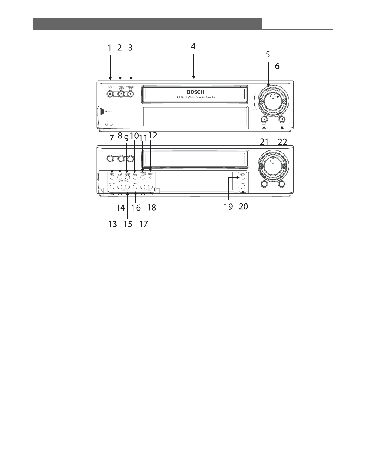
1. REC (RECORD) - Press to begin recording.
2. STOP/EJECT - Press once to discontinue all tape
related functions. Press a second time to eject the
cassette.
3. STANDBY/ON - Press to switch the recorder on;
press again to return to the standby mode.
4. Cassette loading slot - Cassette tape is inserted in
this slot.
5. Shuttle Ring - The shuttle ring is the outer dial.
When the VCR is in STOP mode, the shuttle ring
can be rotated to the left or right then released, and
the VCR will engage in the REWIND or
FORWARD function. While in the PLAYBACK
mode, the shuttle ring can be rotated and held to
engage the search mode. Releasing the shuttle ring
returns it to the PLAYBACK function. Refer to
paragraph 5.6.1 for detailed operation.
6. Jog Ring - The jog ring is the center dial of the jogshuttle ring. This ring is used to advance or reverse
the video by single field when in the still mode.
Refer to paragraph 5.6.1 for detailed operation.
High Density Video Cassette Recorder | Instruction Manual | Controls
Bosch Security Systems | 26 Feb 2003 | Draft
EN
|
6
Figure 1: Front Panel Controls
7. MENU - Press to display and change the
settings of the VCR. The menu is displayed on the
video monitor.
8. TRACKING < - If noise appears on the screen
during playback, press to adjust the tracking during
the playback or slow mode.
V-LOCK - (Selected On/Off via the menu options)
- If a picture is vertically vibrating during still mode
or playback, press V-LOCK buttons until the
vertical jitter on the Screen is reduced
MOVE (Menu operation) - Press to scroll down
through menu screen.
9. TRACKING > - If noise appears on the screen
during playback, press to adjust the tracking during
the playback or slow mode.
V-LOCK + (Selected On/Off via the menu options)
- If a picture is vertically vibrating during still mode
or playback, press V-LOCK buttons until the
vertical jitter on the Screen is reduced
SELECT (Menu operation) - Press to enter the
next menu screen or to change a value.
10. CLEAR - Press to delete the information stored on
the screen display, such as Alarm review, Power fail
and Timer program. It can also be used to stop the
buzzer sound.
11. CLOCK/COUNTER - Press to toggle between the
CLOCK, COUNT and REMAIN displays.
CLOCK shows the current time, COUNT shows
the incremental counter for recording or playing,
and REMAIN indicates the remaining time on the
tape.
12. RESET - Initializes the unit when pressed.
13. REC LOCK - Press REC LOCK to lock the
recording mode, to prevent inadvertant stopping of
the recording. The VCR stays in the record mode.
Press again to unlock.
14. SPEED- - Selects the record/playback tape speed Press to select from a decending order, the record/
playback speed (30H, 18H, 6H...).
High Density Video Cassette Recorder | Instruction Manual | Controls
Bosch Security Systems | 26 Feb 2003 | Draft
EN
|
7
15. SPEED + - Selects the record/playback tape speed
- Press to select from an ascending order, the
record/ playback speed (6H, 18H, 30H...).
16. TIMER - Press to select the programmed recording
timer on/off.
17. SHARPNESS- - Press to sharpen the picture when
in PLAYBACK, SLOW, STILL, CUE and REV
modes.
18. SHARPNESS + - Press to sharpen the picture
when in PLAYBACK, SLOW, STILL, CUE and
REV modes.
19. ALARM - Press to set the ALARM mode On/Off
20. AUDIO - Press to set the AUDIO mode On/Off
when in 6H, 18H, or 30H playback option.
21. PLAY/REC CHECK - Press to play back a
previously recorded tape. Pressing this button while
recording provides confirmation of the recording
operation. The tape plays back the last 4 seconds of
video then returns to the recording mode.
22.PAUSE/STILL - When pressed during recording,
tape movement stops temporarily. Press REC
button to continue the recording. When pressed
during playback, tape movement stops. Press again
to advance by still frame. Press the PLAY button to
continue playback.
Display Window Indications:
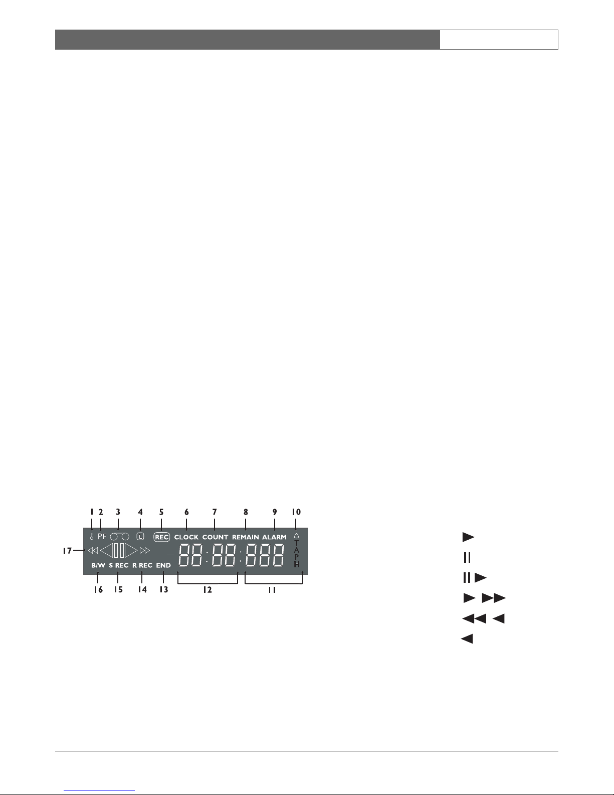
Figure 2: Display Window
1. RECORD LOCK - Illuminates when the record
lock function is operational.
2. PF - Illuminates when the VCR power had failed.
3. Cassette status - Illuminates when a cassette is
located in the recorder.
4. TIMER - Illuminates when the timer recording
mode is on.
5. REC - Illuminates when recording mode is
operating and TIMER is set on.
6. CLOCK - Displays the current time.
7. COUNT - Displays the relative position on the
tape.
8. REMAIN - Displays the remaining time on the
tape.
9. ALARM - Illuminates when the alarm mode is on.
10. ALARM - Illuminates during alarm recording.
Flashes when alarm recording ends or
acknowledged.
11. DIGIT - Displays the tape speed during
playback/recording.
12. FUNCTION indicator - Displays the time, counter,
remain indication.
13. END - Illuminates when the tape reaches the end.
14. R-REC - Illuminates when repeat recording option
is selected.
15. S-REC - Illuminates when you use two or more
VCRs in series.
16. B/W - Illuminates when the B/W mode option is
selected.
17. VCR indicator - Displays the current VCR
operational function as listed in the table below:
VCR Indication - Playback Display
PLAYBACK
STILL
SLOW PLAYBACK
FORWARD SEARCH (CUE)
REVERSE SEARCH (REVIEW)
REVERSE PLAYBACK
High Density Video Cassette Recorder | Instruction Manual | Controls
Bosch Security Systems | 26 Feb 2003 | Draft
EN
|
8
VCR Indication - Display other than Playback
RECORDING
PAUSE
TIMER RECORDING
ALARM RECORDING
REWINDING
FAST FORWARDING
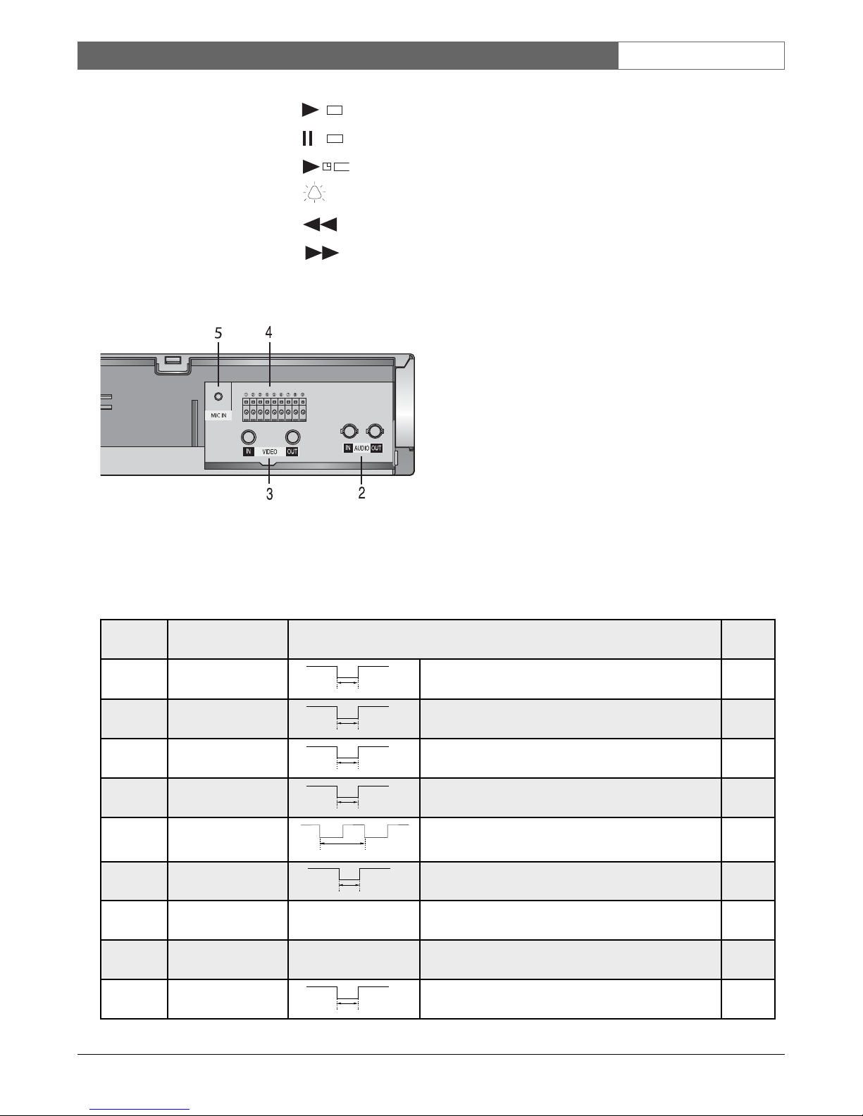
Rear Connection Panel
Figure 3: Rear Panel Connection
1. POWER CORD - Connect to correct power
supply.
2. AUDIO IN/OUT - Accepts an audio signal from a
camera, external sound equipment or another
recorder (Line: –8.8 dBm, 47 kOhm, unbalanced).
Provides an audio output for a monitor or another
VCR (–5.8 dBm, 1.0 kOhm, unbalanced).
3. VIDEO IN/OUT - IN - Receives video signal from
a video camera or another VCR. OUT - For
connection to monitor.
4. 9-PIN TERMINAL - Provides inputs/outputs for
operational use:
Pin 1 – Alarm IN
Pin 2- Alarm OUT
Pin 3 – Series IN
Pin 4 – Series OUT
Pin 5 – Tape end OUT
Pin 6 – VEXT OUT
Pin 7 - GND
Pin 8 - Key IN
Pin 9 - 1-Shot record IN
5. MIC-IN TERMINAL - Input connector for
microphone.
REC
REC
REC
Terminal Function Signal Level In/Out
1 Alarm IN VIH: 4-5V VIL: 0--.6V, T : above 500 msec IN
2 Alarm OUT VOH: Open collector VOL: 0--.6V, T : Alarm rec. state OUT
3 Series IN VIH: 4-5V VIL: 0--.6V, T : above 500 msec IN
4 Series OUT VOH: 4-5V VOL: 0--.6V, T : about 1 sec OUT
5 Tape End OUT VOH: 4-5V VOL: 0--.6V, T : more than 2 sec end of
tape or low tape or DECK error
OUT
6 VEXT VOH: 4-5V VOL: 0--.6V, T : about 20 msec OUT
7 GND 0 V COM
8 Key IN Remocon pulse data IN
9 1-Shot Record IN VIH: 4-5V VIL: 0--.6V, T : above 500 msec IN
V
IH
V
IL
T
V
OH
V
OL
T
V
IH
V
IL
T
V
IH
V
IL
T
V
OH
V
OL
T
V
OH
V
OL
T
V
OH
V
OL
T
 Loading...