

Bosch Rexroth HAB10-330-4X/2G09G-2E111-CE, Rexroth HAB, Rexroth HAB6-350-4X/2G07G-2N111-CE, Rexroth HAB10-330-4X/2G09G-2N111-CE, Rexroth HAB20-330-4X/2G09G-2E111-CE Operating Instructions Manual
...
Bladder-type accumulator
Type HAB
Component series 4X
Nominal volume 1 to 50 liters
Maximum operating pressure 350 bar
RE 50170/12.10
Replaces: 01.09
1/18
Table of contents
Contents Page
Features 1
Ordering code 2
Operating instructions and declarations of conformity 2
Function, section, symbol 3
Technical data 4
Application, mode of operation 5
Calculation 5 to 10
Unit dimensions, standard types 11
Accessories 12 to 16
Intended use 17
Safety instructions for hydraulic accumulators 17
Legal provisions 17
Safety devices 17
Information on available spare parts:
www.boschrexroth.com/spc
Features
– Hydraulic accumulator as per Pressure Equipment Directive
97/23/EC
– Bladder material for different applications
Use:
– Energy storage in systems with intermittent operation
– Energy reserve for emergencies
– Compensation of leakage losses
– Shock and vibration absorption
– Volume compensation in case of pressure and tempera-
ture changes
Note
The Pressure Equipment Directive 97/23/EC of the European
Parliament and the Council of 29 May 1997 on the approximation of the laws of the Member States has been in effect since
29 November 1999. Since 29 May 2002, the marketing of hydraulic accumulators must exclusively satisfy this directive.

2/18 Bosch Rexroth AG Hydraulics HAB RE 50170/12.10
Ordering code
HAB 4X 2 G 2 1 1 1
Nominal volume
1 liter = 1
2.5 liters = 2,5
4 liters = 4
6 liters = 6
10 liters = 10
20 liters = 20
35 liters = 35
50 liters = 50
Max. admissible operating pressure
350 bar (1 to 6 liters) = 350
330 bar (10 to 50 liters) = 330
Component series
Component series 40 to 49 = 4X
(identical installation and connection
dimensions)
Gas filling pressure
2 bar = 2
Connection size for hydraulic fluid
G 3/4 = G05
G 1 1/4 = G07
G 2 = G09
Mounting type (oil port form)
Thread with sealing surface, radial on the inside = G
1)
*
Further details in the
plain text
e.g. special versions
Certification (acceptance)
CE = Acceptance according
to 97/23/EC
BA = Instructions for use
Surface of the connection side
1 = Steel
Surface of the tank inside
1 = Steel
Tank material
1 = Steel
Bladder material
N = NBR
E = ECO
Gas port form
2 = Gas valve for filling and testing device
(see page 14)
Order example:
HAB10-330-4X/2G09G-2N111-CE
1)
1)
1)
1)
1)
Other variants upon request
Operating instructions and declarations of conformity
Operating instructions
applicable to HAB1 to HAB50
Language
Operating instructions
German R901200925
English R901200926
French R901200927
Spanish R901200928
Italian R901200929
Chinese R901200930
Russian R901200931
Norwegian R901200932
Polish R901278729
Czech R901278730
Material no.
Declarations of conformity
Language: German, English, French
Nominal
volume
1 l – –
2.5 l
4 l
6 l
10 l
20 l
35 l
50 l
Standard types see page 11
Declaration of conformity
Bladder material NBR
Material no.
Bladder material ECO
Material no.
R901200940 R901200942
R901200941 R901200943

Function, section, symbol
Hydraulics Bosch Rexroth AGRE 50170/12.10 HAB 3/18
General
Hydraulic accumulators are hydrostatic devices that are able
to save a certain amount of energy and release it to the hydraulic system, if necessary.
Liquids are only compressible to a very small extent; gases,
however, are very compressible. The working principle of all
gas-filled hydraulic accumulators is based on that difference.
4
7
1
If a certain pressurized gas quantity is pressurized with a
higher liquid pressure, the gas volume decreases with increasing liquid pressure whereas the gas pressure increases
with the liquid pressure.
If the liquid pressure decreases, the extending gas presses
the liquid back into the hydraulic system until the pressure is
equalized again.
Bladder-type accumulators
Bladder-type accumulators consist of a seamlessly produced
cylindrical pressure vessel (1) made of high-tensile steel.
The elastic bladder (2) mounted in the interior divides the accumulator into a gas and a fluid side.
Via the gas valve (4), the bladder is filled with nitrogen to the
provided gas filling pressure p
8
6
.
0
4.1
4
4.2
4.3
5
2
3
1 Tank
2 Bladder
3 Oil valve
4 Gas valve
5 Gas valve
support
6 Nut
7 Type cap
8 Cover cap
Depending on the design of the separating element, you distinguish between bladder-type and diaphragm-type accumulators. Hydraulic accumulators basically consist of a liquid and
a gas part with a gas-tight separating element. The liquid part
is connected to the hydraulic circuit.
If the fluid is now pressed into the accumulator, the gas in the
bladder is compressed and in this way, a pressure increase
is achieved. The gas volume decreases and on the fluid side,
the fluid can flow into the accumulator. As soon as the pressure on the fluid side decreases under the gas pressure, the
accumulator is emptied.
In the bladder-type accumulator oil port, there is the oil
valve (3) which closes if the pressure on the gas side exceeds the pressure on the fluid side. In this way, exit of the
bladder into the oil channel and destruction of the bladder are
avoided.
If the minimum operating pressure is reached, a small fluid
volume (approx. 10 % of the hydraulic accumulator nominal
volume) is to remain between bladder and oil valve so that
the bladder does not hit the valve in every expansion process.
The gas valve (4) consists of sealing cap (4.1), gas valve insert (4.2) and gas filling valve body (4.3). These parts can be
exchanged individually.
The type cap (7) contains the technical data and features of
the hydraulic accumulator.
Symbol

4/18 Bosch Rexroth AG Hydraulics HAB RE 50170/12.10
Technical Data (For applications outside these parameters, please consult us!)
general
Weight kg See table page 11
Design Bladder-type accumulator
Installation position Fluid connection socket at the bottom, others on request
Mounting type with clamps and console
Ambient temperature range °C –15 to +65
Line connection Screw-in thread
hydraulic
Nominal volume V
Effective gas volume V
Max. adm. flow q
Max. admissible operating
pressure
nom
eff
max
p
bar 350 350 350 350 330 330 330 330
max
l 1 2.5 4 6 10 20 35 50
l 1.0 2.4 3.7 5.9 9.2 18.1 33.4 48.7
l/min 240 600 600 600 900 900 900 900
1)
Max. adm. pressure
fluctuation range
Δp
bar 200 200 200 200 200 200 200 200
dyn
Operating pressures and useful volumes See calculation page 5 to 10
Hydraulic fluid Hydraulic oil according to DIN 51524; other liquids on request!
Hydraulic fluid temperature range
Others on request
°C –15 to +80 (NBR)
–35 to +80 (ECO)
pneumatic
Charging gas Nitrogen, purity class 4.0, N2 = 99.99 vol. %
Gas filling pressure p
Hydraulic fluids that can be used
Hydraulic fluids Temperature range Material
Mineral oils –15 to +80 °C
–35 to +80 °C
HFC –10 to +60 °C NBR
bar 2
0
NBR Acrylonitrile-butadiene rubber (Perbunan)
NBR
ECO Epichlorhydrin rubber
ECO
For other hydraulic fluids and temperatures, please contact us.
Application, mode of operation
Hydraulics Bosch Rexroth AGRE 50170/12.10 HAB 5/18
Applications
Hydro-pneumatic accumulators offer versatile applications:
– Energy storage for saving pump drive power in systems
with intermittent operation.
– Energy reserve for emergencies, e.g. in case of hydraulic
pump failure.
– Compensation of leakage losses.
– Shock and vibration absorption in periodic vibrations.
– Volume compensation in case of pressure and tempera-
ture changes.
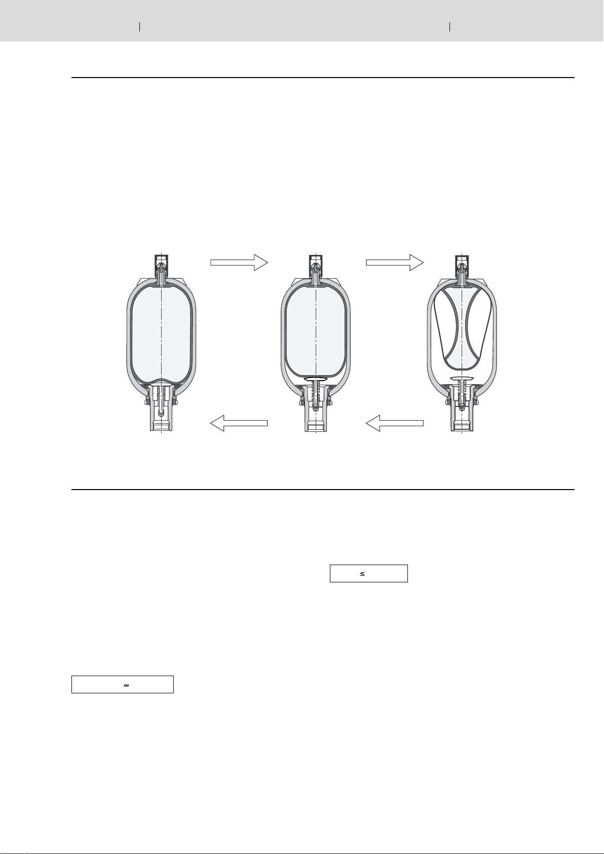
Charge
V
0
p
0
V
p
Mode of operation
Liquids are almost incompressible and are therefore not able
to store pressure energy. In hydro-pneumatic Rexroth accumulators, the compressibility of a gas is used for the fluid storage. You may only use nitrogen of cleanliness class 4.0!
N
= 99.99 vol. %
2
Charge
1
1
V
2
p
2
Discharge Discharge
Calculation
Pressures
In the accumulator calculation, the following pressures are of
vital importance:
p0 = Gas filling pressure at room temperature
and drained fluid chamber
p
(t ) = Gas filling pressure at operating temperature
0
p0 (t
) = Gas filling pressure at max. operating temperature
max
p
= Minimum operating pressure
1
p
= Maximum operating pressure
2
In order to achieve the best utilization of the accumulator volume possible as well as long service life, compliance with the
following values is recommended:
p0 (t
) 0.9 p
max
1
(1)
The largest hydraulic pressure is not to exceed four times the
filling pressure as otherwise, the bladder elasticity is greatly
strained and excessive compression changes with considerable gas heating result:
p2 4 • p
0
(2)
The accumulator bladder service life is the longer the smaller
the difference between p
and p2. This, however, results in
1
the reduction in the corresponding degree of utilization of the
maximum storage capacity.

0
6/18 Bosch Rexroth AG Hydraulics HAB RE 50170/12.10
Calculation
Oil volume
According to the pressures p
V
… V2 result.
0
… p2, the gas volumes
0
In this connection, V0 is also the accumulator's nominal volume.
The available oil volume V corresponds to the difference of
the gas volumes V
V V1 – V
and V2:
1
2
(3)
The gas volume that can be changed within one pressure difference is determined by the following equations:
a) To isothermal changes of condition of gases, i.e. if the
gas cushion changes so slowly that there is enough time
for the complete heat exchange between the nitrogen and
its environment and the temperature therefore remains
constant, the following applies:
p0 • V0 = p1 • V1 = p2 • V
(4.1)
2
Calculation diagram
For the graphical determination, the formulas (4.1) and (4.2)
in diagrams on pages 7 to 10 are implemented. Depending
on the task, the available oil volume, the accumulator size or
the pressures can be determined.
Available oil
volume
Correction factor K
and K
i
a
The equation (4.1) or (4.2) is only true for ideal gases. In
the behavior of real gases, considerable deviations result at
operating pressures of more than 200 bar, which have to be
considered by correction factors. They can be seen from the
following diagrams. The correction factors by which the ideal
sampling volume
V is to be multiplied lie within the range
from 0.6 … 1.
b) To adiabatic changes of condition, i.e. if the gas cushion
changes quickly with the nitrogen temperature changing as
well, the following applies:
p0 • V
χ
= p1 • V
0
χ
= p2 • V
1
(4.2)
χ
2
χ = Ratio of the specific heats of the gases
(adiabatic exponent), for nitrogen = 1.4
In practice, the changes of condition rather follow adiabatic
laws. The charging is often isothermal, the discharge adiabatic.
Considering the equations (1) and (2), V lies at 50 % to
70 % of the nominal accumulator volume. As reference
point, the following applies:
V0 = 1.5 … 3 x V
(5)
Application of the calculation diagrams
(see page 7 to 10)
Gas filling pressure
V
V in l →
2
V
1
s
2
po
s
1
p in bar →
P
P
1
2
Working pressure range
→
K
i
i
K
Isothermal
1,0
0,9
0,8
0,7
0,6
0,1
0,2 0,3 0,4 0,5 0,6 0,7 0,8 0,9 1,
V
p1 / p2 →
real
= V
ideal
• K
V
= V
i
Adiabatic
real
ideal
• K
a
1,0
→
K
0,9
0,8
a
p
2
= 200 bar
p
2
= 300 bar
0,7
0,6
0,1
0,2 0,3 0,4 0,5 0,6 0,7 0,8 0,9 1,0
p
/ p2 →
1
 Loading...