

Page 1
OBJ_DOKU-12946-002.fm Page 1 Monday, August 22, 2016 3:40 PM
Robert Bosch Power Tools GmbH
70538 Stuttgart
GERMANY
www.bosch-pt.com
1 609 92A 233 (2016.08) O / 28
PWS
1000 | 1500
en Original instructions
ja オリジナル取扱説明書
Page 2
OBJ_BUCH-758-002.book Page 2 Monday, August 22, 2016 3:41 PM
2 |
English . . . . . . . . . . . . . . . . . . . . . . . . . . . . . . . . . . . . . . . . . . Page 6
日本語 . . . . . . . . . . . . . . . . . . . ページ 14
. . . . . . . . . . . . . . . . . . . . . . . . . . . . . . . . . . . . . . . . . . . . . . . . . I
1 609 92A 233 | (22.8.16) Bosch Power Tools
Page 3
OBJ_BUCH-758-002.book Page 3 Monday, August 22, 2016 3:41 PM
| 3
Bosch Power Tools 1 609 92A 233 | (22.8.16)
Page 4
1
7
6
8
9
10
13
11
12
6
2
4
3
4
21
OBJ_BUCH-758-002.book Page 4 Monday, August 22, 2016 3:41 PM
4 |
1 609 92A 233 | (22.8.16) Bosch Power Tools
Page 5
PWS 1000
PWS 1500
15
16
17
14
18
14
5
10
11
20
8
19
OBJ_BUCH-758-002.book Page 5 Monday, August 22, 2016 3:41 PM
| 5
Bosch Power Tools 1 609 92A 233 | (22.8.16)
Page 6
OBJ_BUCH-758-002.book Page 6 Monday, August 22, 2016 3:41 PM
6 | English
Prevent unintentional starting. Ensure the switch is in
English
Safety Notes
General Power Tool Safety Warnings
WARNING
instructions may result in electric shock, fire and/or serious
injury.
Save all warnings and instructions for future reference.
The term “power tool” in the warnings refers to your mainsoperated (corded) power tool or battery-opera ted (cordless)
power tool.
Work area safety
Keep work area clean and well lit. Cluttered or dark areas
invite accidents.
Do not operate power tools in explosive atmospheres,
such as in the presence of flammable liquids, gases or
dust. Power tools create sparks which may ig nite the dust
or fumes.
Keep children and bystanders away while operating a
power tool. Distractions can cause you to lose control.
Electrical safety
Power tool plugs must match the outlet. Never modify
the plug in any way. Do not use any adapter plugs with
earthed (grounded) power tools. Unmodified plugs and
matching outlets will reduce risk of electric shock.
Avoid body contact with earthed or grounded surfaces,
such as pipes, radiators, ranges and refrigerators.
There is an increased risk of electric shock if your body is
earthed or grounded.
Do not expose power tools to rain or wet conditions.
Water entering a power tool will increase the risk of electric
shock.
Do not abuse the cord. Never use the cord for carrying,
pulling or unplugging the power tool. Keep cord away
from heat, oil, sharp edges and moving parts. Damaged
or entangled cords increase the risk of electric shock.
When operating a power tool outdoors, use an exten-
sion cord suitable for outdoor use. Use of a cord s uitable
for outdoor use reduces the risk of electric shock.
If operating a power tool in a damp location is unavoid-
able, use a residual current device (RCD) protected
supply. Use of an RCD reduces the risk of electric shock.
Personal safety
Stay alert, watch what you are doing and use common
sense when operating a power tool. Do not use a power
tool while you are tired or under the influence of drugs,
alcohol or medication. A moment of inattention while op-
erating power tools may result in serious personal injury.
Use personal protective equipmen t. Always wear eye
protection. Protective equipment such as dust mask,
non-skid safety shoes, hard hat, or hearing protection used
for appropriate conditions will reduce personal injuries.
1 609 92A 233 | (22.8.16) Bosch Power Tools
Read all safety warnings and all instructions. Failure to follow the warnings and
the off-position before connecting to power source
and/or battery pack, picking up or carrying the tool.
Carrying power tools with your finger on the switch or energising power tools that have the switch on invites accidents.
Remove any adjusting key or wrench before turning
the power tool on. A wrench or a key left attached to a ro-
tating part of the power tool may result in personal injury.
Do not overreach. Keep proper footing and balance at
all times. This enables better control of the power tool in
unexpected situations.
Dress properly. Do not wear loose clothing or jewel-
lery. Keep your hair, clothing and gloves away from
moving parts. Loose clothes, jewellery or long hair can be
caught in moving parts.
If devices are provided for the connection of dust ex-
traction and collection facilities, ensure these are connected and properly used. Use of dust collection can re-
duce dust-related hazards.
Power tool use and care
Do not force the power tool. Use the correct power tool
for your application. The correct power tool will do the
job better and safer at the rate for which it was designed.
Do not use the power tool if the switch does not turn it
on and off. Any power tool that cannot be controlled with
the switch is dangerous and must be repaired.
Disconnect the plug from the power source and/or the
battery pack from the power tool before making any
adjustments, changing accessories, or storing power
tools. Such preventive safety measures reduce the risk of
starting the power tool accidentally.
Store idle power tools out of the reach of children and
do not allow persons unfamiliar with the power tool or
these instructions to operate the power tool. Power
tools are dangerous in the hands of untrained users.
Maintain power tools. Check for misalignment or bind-
ing of moving parts, breakage of parts and any other
condition that may affect the power tool’s operation. I f
damaged, have the power tool repaired before use.
Many accidents are caused by poorly maintained power
tools.
Keep cutting tools sharp and clean. Properly maintained
cutting tools with sharp cutting edges are less likely to bind
and are easier to control.
Use the power tool, accessories and tool bits etc. in ac-
cordance with these instructions, taking into account
the working conditions and the work to be performed.
Use of the power tool for operations different from those
intended could result in a hazardous situation.
Service
Have your power tool serviced by a qualified repair per-
son using only identical replacement parts. This will en-
sure that the safety of the power tool is maintained.
Page 7
OBJ_BUCH-758-002.book Page 7 Monday, August 22, 2016 3:41 PM
Safety Warnings for Angle Grinder
Hold the power tool by insulated gripping surfaces on-
Safety Warnings common for Grinding, Sanding, Wire
Brushing or Abrasive Cutting Off Operations
This power tool is intended to function as a grinder,
sander, wire brush or cut-off tool. Read all safety warnings, instructions, illustrations and specifications provided with this power tool. Failure to follow all instruc-
Position the cord clear of the spinning accessory. If you
tions listed below may result in electric shock, fire and/or
serious injury.
Operations such as polishing are not recommended to
Never lay the power tool down until the accessory has
be performed with this power tool. Operations for which
the power tool was not designed may create a hazard and
cause personal injury.
Do not run the power tool while carrying it at your side.
Do not use accessories which are not specifically de-
signed and recommended by the tool manufacturer.
Just because the accessory can be attached to your power
tool, it does not assure safe operation.
The rated speed of the accessory must be at least equal
to the maximum speed marked on the power tool. Ac-
cessories running faster than their rated speed can break
and fly apart.
The outside diameter and the thickness of your acces-
Do not operate the power tool near flammable materi-
Do not use accessories that require liquid coolants. Us-
sory must be within the capacity rating of your power
tool. Incorrectly sized accessories cannot be adequately
guarded or controlled.
Threaded mounting of accessories must match the grind-
Kickback and related warnings
Kickback is a sudden reaction to a pinched or snagged ro-
er spindle thread. For accessories mounted by flanges,
the arbour hole of the accessory must fit the locating diameter of the flange. Accessories that do not match the
mounting hardware of the power tool will run out of balance,
vibrate excessively and may cause loss of control.
Do not use a damaged accessory. Before each use in-
spect the accessory such as abrasive wheels for chips
and cracks, backing pad for cracks, tear or excess
wear, wire brush for loose or cracked wires. If power
tool or accessory is dropped, inspect for damage or install an undamaged accessory. After inspecting and installing an accessory, position yourself and bystanders
away from the plane of the rotating accessory and run
the power tool at maximum no-load speed for one minute. Damaged accessories will normally break apart during
this test time.
Wear personal protective equipment. Depending on
Maintain a firm grip on the power tool and position your
application, use face shield, safety goggles or safety
glasses. As appropriate, wear dust mask, hearing protectors, gloves and workshop apron capable of stopping small abrasive or workpiece fragments. The eye
protection must be capable of stopping flying debris generated by various operations. The dust mask or respirator
Never place your hand near the rotating accessory.
must be capable of filtrating particles generated by your
operation. Prolonged exposure to high intensity noise may
cause hearing loss.
Do not position your body in the area where power tool
Keep bystanders a safe distance away from work area.
Anyone entering the work area must wear personal
protective equipment. Fragments of workpiece or of a
broken accessory may fly away and cause injury beyond
immediate area of operation.
English | 7
ly, when performing an operation where the cutting accessory may contact hidden wiring or its own cord. Cut-
ting accessory contacting a “live” wire may make exposed
metal parts of the power tool “live” and could give the operator an electric shock.
lose control, the cord may be cut or snagged and your hand
or arm may be pulled into the spinning wheel.
come to a complete stop. The spinning wheel may grab
the surface and pull the power tool out of your control.
Accidental contact with the spinning accessory could snag
your clothing, pulling the accessory into your body.
Regularly clean the power tool’s air vents. The motor’s
fan will draw the dust inside the housing and excessive accumulation of powdered metal may cause electrical hazards.
als. Sparks could ignite these materials.
ing water or other liquid coolants may result in electrocution or shock.
tating wheel, backing pad, brush or any other accessory.
Pinching or snagging causes rapid stalling of the rotating
accessory which in turn causes the uncontrolled power
tool to be forced in the direction opposite of the accessory’s rotation at the point of the binding.
For example, if an abrasive wheel is snagged or pinche d by
the workpiece, the edge of the wheel that is entering into
the pinch point can dig into the surface of the material
causing the wheel to climb out or kick out. The wheel may
either jump toward or away from the operator, depending
on direction of the wheel’s movement at the point of pinching. Abrasive wheels may also break under these conditions.
Kickback is the result of power tool misuse and/or incorrect operating procedures or conditions and can be avoided by taking proper precautions as given below.
body and arm to allow you to resist kickback forces. Always use auxiliary handle, if provided, for maximum
control over kickback or torque reaction during
start-up. The operator can control torque reactions or
kickback forces, if proper precautions are taken.
Accessory may kickback over your hand.
will move if kickback occurs. Kickback will propel the
tool in direction opposite to the wheel’s movement at the
point of snagging.
Bosch Power Tools 1 609 92A 233 | (22.8.16)
Page 8
OBJ_BUCH-758-002.book Page 8 Monday, August 22, 2016 3:41 PM
8 | English
Use special care when working corners, sharp edges,
Do not restart the cutting operation in the workpiece.
etc. Avoid bouncing and snagging the accessory. Corners, sharp edges or bouncing have a tendency to snag the
rotating accessory and cause loss of control or kickback.
Do not attach a saw chain woodcarving blade or
Support panels or any oversized workpiece to minimize
toothed saw blade. Such blades create frequent kickback
and loss of control.
Safety warnings specific for Grinding and Abrasiv e Cutting-Off operations
Use only wheel types that are recommended for your
Use extra caution when making a “pocket cut” into ex-
power tool and the specific guard designed for the selected wheel. Wheels for which the power tool was not de-
signed cannot be adequately guarded and are unsafe.
The grinding surface of the centre depressed wheels
must be mounted below the plane of the guard lip. An
Safety warnings specific for sanding operations
improperly mounted wheel that projects through the plane
of the guard lip cannot be adequately protected.
The guard must be securely attached to the power tool
and positioned for maximum safety, so the least
amount of wheel is exposed towards the operator. The
guard helps to protect operator from broken wheel fragments, accidental contact with wheel and sparks that
Safety warnings specific for wire brushing operations
Be aware that wire bristles are thrown by the brush
could ignite clothing.
Wheels must be used only for recommended applica-
tions. For example: do not grind with the side of the
cut-off wheel. Abrasive cut-off wheels are intended for
If the use of a guard is recommended for wire brushing,
peripheral grinding; side forces applied to these wheels
may cause them to shatter.
Always use undamaged wheel flanges that are of cor-
rect size and shape for your selected wheel. Proper
Additional safety warnings
wheel flanges support the wheel thus reducing the possibility of wheel breakage. Flanges for cut-off wheels may be
different from grinding wheel flanges.
Do not use worn down reinforced wheels from larger
power tools. Wheels intended for larger power tools are
not suitable for the higher speed of a smaller tool and may
burst.
Use suitable detectors to determine if utility lines are
Additional safety warnings specific for abrasive cutting
off operations
Do not “jam” the cut-off wheel or apply excessive pres-
sure. Do not attempt to make an excessive depth of cut.
Overstressing the wheel increases the loading and susceptibility to twisting or binding of the wheel in the cut and the
Release the On/Off switch and set it to the off position
possibility of kickback or wheel breakage.
Do not position your body in line with and behind the
rotating wheel. When the wheel, at the point of operation,
is moving away from your body, the possible kickback may
When working with the machine, always hold it firmly
propel the spinning wheel and the power tool directly at
you.
When wheel is binding or when interrupting a cut for
Do not touch grinding and cutting discs before they
any reason, switch off the power tool and hold the power tool motionless until the wheel comes to a complete
stop. Never attempt to remove the cut-off wheel from
Secure the workpiece. A workpiece clamped with clamp-
the cut while the wheel is in motion otherwise kickback
may occur. Investigate and take corrective action to elimi-
nate the cause of wheel binding.
Let the wheel reach full speed and carefully re-enter
the cut. The wheel may bind, walk up or kickback if the
power tool is restarted in the workpiece.
the risk of wheel pinching and kickback. Large workpieces tend to sag under their own weight. Supports must
be placed under the workpiece near the line of cut and near
the edge of the workpiece on both sides of the wheel.
isting walls or other blind areas. The protruding wheel
may cut gas or water pipes, electrical wiring or objects that
can cause kickback.
Do not use excessively oversized sanding disc paper.
Follow manufacturers recommendations, when selecting sanding paper. Larger sanding paper extending be-
yond the sanding pad presents a laceration hazard and
may cause snagging, tearing of the disc, or kickback.
even during ordinary operation. Do not overstress the
wires by applying excessive load to the brush. The wire
bristles can easily penetrate light clothing and/or skin.
do not allow any interference of the wire wheel or
brush with the guard. Wire wheel or brush may expand in
diameter due to work load and centrifugal forces.
Wear safety goggles.
hidden in the work area or call the local utility company
for assistance. Contact with electric lines can lead to fire
and electric shock. Damaging a gas line can lead to explosion. Penetrating a water line causes property damage or
may cause an electric shock.
whe n the p ower suppl y is in terr upted , e. g ., in case o f a
power failure or when the mains plug is pulled. This pre-
vents uncontrolled restarting.
with both hands and provide for a secure stance. The
power tool is guided more secure with both hands.
have cooled down. The discs can become very hot while
working.
ing devices or in a vice is held more secure than by hand.
1 609 92A 233 | (22.8.16) Bosch Power Tools
Page 9
OBJ_BUCH-758-002.book Page 9 Monday, August 22, 2016 3:41 PM
Products sold in GB only: Your product is fitted with a
BS 1363/A approved electric plug with internal fuse
(ASTA approved to BS 1362).
If the plug is not suitable for your socket outlets, it should
be cut off and an appropriate plug fitted in its place by an
authorised customer service agent. The replacement plug
should have the same fuse rating as the original plug.
The severed plug must be disposed of to avoid a possible
shock hazard and should never be inserted into a mains
socket elsewhere.
Prod ucts so ld in AUS and NZ o nly: Use a residual current
device (RCD) with a rated residual current of 30 mA or
less.
Product Description and Specifications
Read all safety warnings and all instructions. Failure to follow the warnings and in-
structions may result in electric shock, fire
and/or serious injury.
Intended Use
The machine is intended for cutting, roughing and brushing of
metal and stone materials without the use of water.
For cutting with bonded abrasives, a special cutting guard
(accessory) must be used.
When cutting in stone, provide for sufficient dust extraction.
With approved sanding tools, the machine can be used for
sanding with sanding discs.
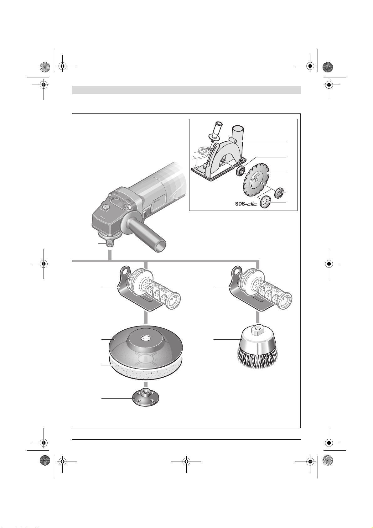
Product Features
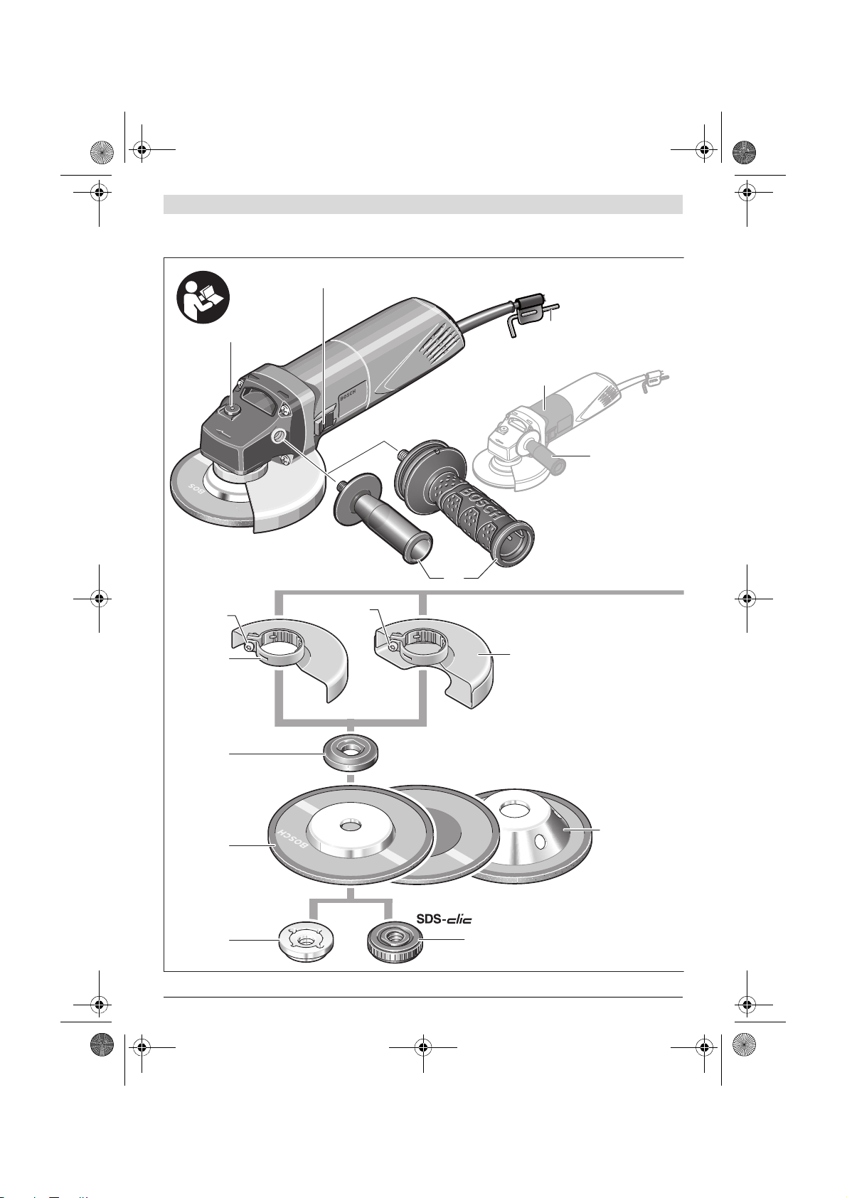
The numbering of the product features refers to the illustration of the machine on the graphics page.
10 Clamping nut
11 Quick-clamping nut *
12 Protection guard for cutting *
13 Carbide grinding head*
14 Hand guard *
15 Rubber sanding plate *
16 Sanding sheet*
17 Round nut *
18 Cup brush *
19 Cutting guide with dust extraction protection guard *
20 Diamond cutting disc *
21 Handle (insulated gripping surface)
*Accessories shown or described are not part of the standard delivery scope of the product. A complete overview of accessories
can be found in our accessories program.
English | 9
1 Spindle lock button
2 On/Off switch
3 Hex key
4 Auxiliary handle
5 Grinder spindle
6 Locking screw for protection guard
7 Protection guard for grinding
8 Mounting flange with O-ring
9 Grinding/cutting disc*
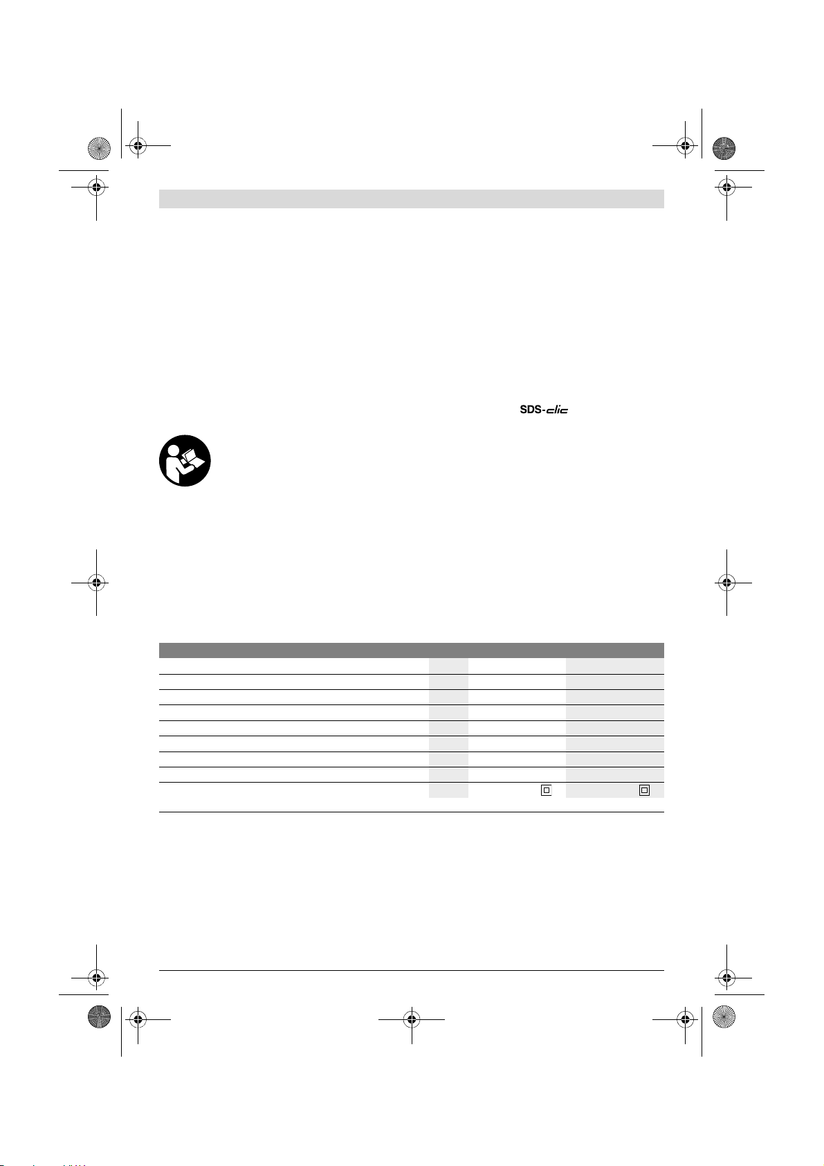
Technical Data
Angle Grinder PWS 1000 PWS 1500
Article number
Rated power input
Output power
Rated speed
Grinding disc diameter, max.
Thread of grinder spindle
Thread length (max.) of grinder spindle
Weight according to EPTA-Procedure 01:2014
Protection class
The values given are valid for a nominal voltage [U] of 230 V. For different vol tages and models for specific countries, these values can vary.
Assembly
Mounting the Protective Devices
Before any work on the machine itself, pull the mains
plug.
Note: After breakage of the grinding disc during operation or
damage to the holding fixtures on the protection guard/power
tool, the machine must promptly be sen t to an afte r-sales service agent for maintenance. For addresses, see section “After-sales Service and Application Service”.
Bosch Power Tools 1 609 92A 233 | (22.8.16)
W670670
W400400
-1
min
mm 100 115
mm 16.5 21
kg 1.8 1.9
Protection Guard for Grinding
Place the protection guard 7 on the spindle collar. Adjust the
position of the protection guard 7 to the requirements of the
operation. Lock the protection guard 7 tightening the locking
screw 6 with a hex key 3.
Adjust the protection guard 7 in such a manner that
sparking is prevented in the direction of the operator.
Note: The encoding keys on the protection guard 7 ensure
that only a protection guard that fits the machine type can be
mounted.
3 603 D11 0.. 3 603 D11 1..
1100 0 1100 0
M 10 M 14
/II / II
Page 10

22
OBJ_BUCH-758-002.book Page 10 Monday, August 22, 2016 3:41 PM
10 | English
Protection Guard for Cutting
For cutting with bonded abrasives, always use the pro-
tection guard for cutting 12.
Provide for sufficient dust extraction when cutting
stone.
The protection guard for cutting 12 is mounted in the same
manner as the protection guard for grinding 7.
Auxiliary Handle
Operate your machine only with the auxiliary handle 4.
Screw the auxiliary handle 4 on the right or left of the machine
head depending on the working method.
Vibration-dampening Auxiliary Handle
The vibration-dampening auxiliary handle reduces the vibrations, making operation more comfortable and secure.
Do not make any alterations to the auxiliary handle.
Do not continue to use an auxiliary handle if it is damaged.
Hand Guard
For operations with the rubber sanding plate 15 or with
the cup brush/wheel brush/flap disc, always mount the
hand guard 14.
The hand guard 14 is fastened with the auxiliary handle 4.
Mounting the Grinding Tools
Before any work on the machine itself, pull the mains
plug.
Do not touch grinding and cutting discs before they
have cooled down. The discs can become very hot while
working.
Clean the grinder spindle 5 and all parts to be mounted.
For clamping and loosening the grinding tools, lock the grind-
er spindle with the spindle lock button 1.
Actuate the spindle lock button only when the grinder
spindle is at a standstill. Otherwise, the machine may be-
come damaged.
Grinding/Cutting Disc
Pay attention to the dimensions of the grinding tools. The
mounting hole diameter must fit the mounting flange without
play. Do not use reducers or adapters.
When using diamond cutting discs, pay attention that the direction-of-rotation arrow on the diamond cutting disc and the
direction of rotation of the machine (see direction-of-rotation
arrow on the machine head) agree.
See graphics page for the mounting sequence.
To fasten the grinding/cutting disc, screw on the clamping nut
10 and tighten with the two-pin spanner; see Section “Quickclamping Nut ”.
After mounting the grinding tool and before switching
on, check that the grinding tool is correctly mounted
and that it can turn freely. Make sure that the grinding
tool does not graze against the protection guard or oth-
er parts.
1 609 92A 233 | (22.8.16) Bosch Power Tools
Flap Disc
For operations with the flap disc, always mount the
hand guard 14.
Rubber Sanding Plate
For operations with the rubber sanding plate 15, al-
ways mount the hand guard 14.
See graphics page for the mounting sequence.
Screw on the round nut 17 and tighten with the two-pin span-
ner.
Cup Brush/Disc Brush
For operations with the cup brush/wheel brush, always
mount the hand guard 14.
See graphics page for the mounting sequence.
The cup brush/disc brush must be able to be screwed onto
the grinder spindle until it rests firmly against the grinder
spindle flange at the end of the grinder spindle threads. Tighten the cup brush/disc brush with an open-end spanner.
Quick-clamping Nut
For convenient changing of grinding tools without the use of
additional tools, you can use the quick-clamping nut 11 instead of the clamping nut 10.
The quick-clamping nut 11 may be used only for grind-
ing or cutting discs.
Use only a flawless, undamaged quick-clamping nut 11.
When screwing on, pay attention that the side of the
quick-clamping nut 11 with printing does not face the
grinding disc; the arrow must point to the index mark 22.
Mounting flange for grinding spindle
M 14: A plastic part (O-ring) is fitted
around the centring collar of mounting
flange 8. If the O-ring is missing or
damaged, the mounting flange 8 must
be replaced before resuming operation.
Mounting flange for grinding spindle
M 10: The mounting flange can be used
on both sides.
Lock the grinder spindle with
the spindle lock button 1. To
tighten the quick-clamping
nut, firmly turn the grinding
disc in clockwise direction.
Page 11

D
b
d
OBJ_BUCH-758-002.book Page 11 Monday, August 22, 2016 3:41 PM
A properly attached, undamaged quick-clamping nut can
be loosened by hand when
turning the knurled r ing in anticlockwise direction.
Never loosen a tight quickclamping nut with pliers. Always use the two-pin spanner. Insert the two-pin span-
ner as shown in the
illustration.
Dust/Chip Extraction
Dust from materials such as lead-containing coatings,
Approved Grinding Tools
All grinding tools mentioned in these operating instructions
can be used.
The permissible speed [min
[m/s] of the grinding tools used must at least match the values
given in the table.
Therefore, observe the permissible rotational/circumferen-
tial speed on the label of the grinding tool.
-1
] or the circumferential speed
Prevent dust accumulation at the workplace. Dust can
Operation
English | 11
some wood types, minerals and metal can be harmful to
one’s health. Touching or breathing-in the dust can cause
allergic reactions and/or lead to respiratory infections of
the user or bystanders.
Certain dust, such as oak or beech dust, is considered car-
cinogenic, especially in connection with wood-treatment
additives (chromate, wood preservative). Materials con-
taining asbestos may only be worked by specialists.
– As far as possible, use a dust extraction system suitable
for the material.
– Provide for good ventilation of the working place.
– It is recommended to wear a P2 filter-class respirator.
Observe the relevant regulations in your country for the
materials to be worked.
easily ignite.
max.
[mm]
D b d [min-1] [m/s]
100
11566
D
100
115––––
70753030M 10
[mm]
16.0
22.2
M14
11000
110008080
11000
110008080
11000
110004545
Rotating the Machine Head
Before any work on the machine itself, pull the mains
plug.
The machine head can be
rotated with respect to
the machine housing in
90° steps. In this manner, the On/Off switch
can be brought into a
more convenient position for special working
situations, e.g. for lefthanded persons.
Completely unscrew the
four screws. Rotate the
without removing it from the housing, to the new position.
Screw in and tighten the four screws again.
machine head carefully,
Starting Operation
Observe correct mains voltage! The voltage of the pow-
er source must agree with the voltage specified on the
nameplate of the machine. Power tools marked with
230 V can also be operated with 220 V.
When operating the machine with power from mobile generators that do not have sufficient reserve capacity or are not
equipped with suitable voltage control with starting current
amplification, loss of performance or untypical behavior can
occur upon switching on.
Please observe the suitability of the power generator being
used, particularly with regard to the mains voltage and frequency.
Switching On and Off
To start the power tool, push the On/Off switch 2 forwards.
To lock the On/Off switch 2, press the On/Off switch 2 down
at the front until it latches.
To switch off the power tool, release the On/Off switch 2 or,
if it is locked, briefly push down the back of the On/Off switch
2 and then release it.
To save energy, only switch the power tool on when using it.
Check grinding tools before using. The grinding tool
must be mounted properly and be able to move freely.
Carry out a test run for at least one minute with no load.
Do not use damaged, out-of-centre or vibrating grinding tools. Damaged grinding tools can burst and cause in-
juries.
Bosch Power Tools 1 609 92A 233 | (22.8.16)
Page 12

OBJ_BUCH-758-002.book Page 12 Monday, August 22, 2016 3:41 PM
12 | English
Working Advice
Exercise caution when cutting slots in structural walls;
see Section “Information on Structures”.
Clamp the workpiece if it does not remain stationary
due to its own weight.
Do not strain the machine so heavily that it comes to a
standstill.
After heavily straining the power tool, continue to run
it at no-load for several minutes to cool down the accessory.
Do not touch grinding and cutting discs before they
have cooled down. The discs can become very hot while
working.
Do not use the power tool with a cut-off stand.
Before any work on the machine itself, pull the mains
plug.
Rough Grinding
Never use a cutting disc for roughing.
The best roughing results are achieved when setting the machine at an angle of 30 ° to 40°. Move the machine back and
forth with moderate pressure. In this manner, the workpiece
will not become too hot, does not discolour and no grooves
are formed.
Flap Disc
With the flap disc (accessory), curved surfaces and profiles
can be worked.
Flap discs have a considerably higher service life, lower noise
levels and lower sanding temperatures than conventional
sanding sheets.
Cutting Metal
For cutting with bonded abrasives, always use the pro-
tection guard for cutting 12.
When cutting, work with moderate feed, adapted to the material being cut. Do not exert pressure onto the cutting disc, tilt
or oscillate the machine.
Do not reduce the speed of running down cutting discs by applying sideward pressure.
The machine must always work in an upgrinding motion. Otherwise, the danger exists
of it being pushed un-
controlled out of the
cut.
When cutting profiles
and square bar, it is best
to start at the smallest
cross section.
Cutting Stone
Provide for sufficient dust extraction when cutting
Wear a dust respirator.
The machine may be used only for dry cutting/grinding.
For cutting stone, it is best to use a diamond cutting disc.
Operate the machine only with dust extraction and additional-
ly wear a dust protection mask.
The vacuum cleaner must be approved for the extraction of
masonry dust. Bosch provides suitable vacuum cleaners.
heat and become damaged as a result. This is clearly indicated
by circular sparking, rotating with the diamond cutting disc.
In this case, interrupt the cutting process and allow the diamond cutting disc to cool by running the machine for a short
time at maximum speed with no load.
Noticeably decreasing work progress and circular sparking
are indications of a diamond cutting disc that has become
dull. Briefly cutting into abrasive material (e. g. lime-sand
brick) can resharpen the disc again.
Information on Structures
Slots in structural walls are subject to the Standard DIN 1053
Part 1, or country-specific regulations.
These regulations are to be observed under all circumstances. Before beginning work, consult the responsible structural
engineer, architect or the construction supervisor.
Maintenance and Service
Maintenance and Cleaning
Before any work on the machine itself, pull the mains
For safe and proper working, always keep the machine
In extreme conditions, always use dust extraction as
Please store and handle the accessory(-ies) carefully.
If the replacement of the supply cord is nece ssary, this has to
be done by Bosch or an authorized Bosch service agent in order to avoid a safety hazard.
stone.
Switch on the machine
and place the front part
of the cutting guide on
the workpiece. Slide the
machine with moderate
feed, adapted to the material to be worked.
For cutting especially
hard material, e. g., concrete with high pebble
content, the diamond
cutting disc can over-
plug.
and ventilation slots clean.
far as possible. Blow out ventilation slots frequently
and install a portable residual current device (PRCD).
When working metals, conductive dust can settle in the interior of the power tool. The total insulation of the power
tool can be impaired.
1 609 92A 233 | (22.8.16) Bosch Power Tools
Page 13

OBJ_BUCH-758-002.book Page 13 Monday, August 22, 2016 3:41 PM
After-sales Service and Application Service
Our after-sales service responds to your questions con cerning maintenance and repair of your product as well as spare
parts. Exploded views and information on spare parts can also be found under:
www.bosch-pt.com
Bosch’s application service team will gladly answer questions
concerning our products and their accessories.
In all correspondence and spare parts orders, please always
include the 10-digit article number given on the nameplate of
the product.
Great Britain
Robert Bosch Ltd. (B.S.C.)
P.O. Box 98
Broadwater Park
North Orbital Road
Denham
Uxbridge
UB 9 5HJ
At www.bosch-pt.co.uk you can order spare parts or arrange
the collection of a product in need of servicing or repair.
Tel. Service: (0344) 7360109
E-Mail: boschservicecentre@bosch.com
KZN – BSC Service Centre
Unit E, Almar Centre
143 Crompton Street
Pinetown
Tel.: (031) 7012120
Fax: (031) 7012446
E-Mail: bsc.dur@za.bosch.com
Western Cape – BSC Service Centre
Democracy Way, Prosperity Park
Milnerton
Tel.: (021) 5512577
Fax: (021) 5513223
E-Mail: bsc@zsd.co.za
Bosch Headquarters
Midrand, Gauteng
Tel.: (011) 6519600
Fax: (011) 6519880
E-Mail: rbsa-hq.pts@za.bosch.com
Disposal
The machine, accessories and packaging should be sorted for
environmental-friendly recycling.
Only for EC countries:
Ireland
Origo Ltd.
Unit 23 Magna Drive
Magna Business Park
City West
Dublin 24
Tel. Service: (01) 4666700
Fax: (01) 4666888
Australia, New Zealand and Pacific Islands
Subject to change without notice.
Robert Bosch Australia Pty. Ltd.
Power Tools
Locked Bag 66
Clayton South VIC 3169
Customer Contact Center
Inside Australia:
Phone: (01300) 307044
Fax: (01300) 307045
Inside New Zealand:
Phone: (0800) 543353
Fax: (0800) 428570
Outside AU and NZ:
Phone: +61 3 95415555
www.bosch.com.au
Republic of South Africa
Customer service
Hotline: (011) 6519600
Gauteng – BSC Service Centre
35 Roper Street, New Centre
Johannesburg
Tel.: (011) 4939375
Fax: (011) 4930126
E-Mail: bsctools@icon.co.za
English | 13
According to the European Directive
2012/19/EU for Waste Electrical and Electronic Equipment and its implementation
into national right, power tools that are no
longer usable must be collected sepa rately
and disposed of in an environmentally correct manner.
Bosch Power Tools 1 609 92A 233 | (22.8.16)
Page 14

OBJ_BUCH-758-002.book Page 14 Monday, August 22, 2016 3:41 PM
14 | 日本語
電動工具を屋外で使用する際には、屋外使用に
日本語
安全上のご注意
電動工具の使用にあたっての安全上のご注意
安全上の注意と指示をすべてよくお読
みください。 安全上の注意と指示事項
を厳守しないと、感電、火災、けが等の事故発生の
恐れがあります。
お読みになった後は、お使いになる方がいつでも見
られる所に必ず保管してください。
本書で使用する用語「電動工具」とは、お手持ちの
電動工具(電源コード使用)およびバッテリー工具
(コードレス)を指します。
作業場の安全
作業場は、いつもきれいに保ち、十分に明るくし
てください。 ちらかった場所や作業台は、事故の
原因となります。
爆発の危険性のある環境(可燃性液体、ガスおよ
び粉塵のある場所)では電動工具を使用しないで
ください。 電動工具から火花が散り、粉塵や蒸気
に引火する恐れがあります。
電動工具のご使用中は、子供や無関係者を近づけ
ないでください。 無関係者により気がそらされる
と、工具に対するコントロールを失ってしまう恐
れがあります。
電気の安全について
電動工具の接続用プラグがコンセントに適してい
ることを確認してください。 プラグは絶対に改造
しないでください。 アースされた電動工具とアダ
プタープラグを併用しないでください。 プラグを
改造したりコンセントが不適合であったりすると
感電の危険性を高めます。
アースされているものに身体を接触させないよう
にしてください(パイプ、暖房器具、電磁コン
ロ、冷蔵庫など)。 身体に電流が流れ、感電の危
険性を高めます。
電動工具を雨中およびぬれた場所で保管・使用し
ないでください。 電気工具内に水分が浸入し、感
電の危険性を高めます。
コードを乱暴に扱わないでください。コードを
持って電動工具を運んだり、コードを引っ張って
電源コンセントから抜いたりしないでください。
コードを熱、油、角のとがった所や電動工具の可
動部分に近づけないでください。 コードが破損し
ていたり、絡み合っていたりすると感電の危険性
を高めます。
湿度の高い環境でやむをえず電動工具を使用する
作業者の安全
油断しないで十分注意して作業を行ってくださ
各自に適した保護具および保護めがねを常時着用
不意な始動は避けてください。 電動工具のスイッ
電動工具のスイッチを入れる前に、必ず調節キー
無理な姿勢で作業をしないでください。 足元を安
きちんとした服装で作業してください。 だぶだぶ
集塵装置の接続ができるものは接続して適切に使
電動工具の慎重な取り扱いおよび使用について
無理のある装置の使用を避けてください。 用途に
損傷した部品がないか点検してください。 スイッ
合った延長コードを使用してください。 延長コー
ドが屋外使用に合っていないと、感電の危険性を
高めます。
場合には、漏電遮断器を併用してください。 漏電
遮断器の使用により、感電のリスクを低下させる
ことができます。
い。 疲れている場合、薬物、医薬品服用およびア
ルコール飲用による影響下にある場合には電動工
具を使用しないでください。 電動工具使用中の一
瞬の不注意が重傷の原因となることがあります。
してください。 けがに備え、電動工具の使用状況
に応じた粉じんマスク、防滑性安全靴、ヘルメッ
ト、耳栓などの作業保護具を使用してください。
チが切れていることを必ず確認してから、電動工
具やバッテリーの電源接続や運搬をおこなってく
ださい。 オン/オフスイッチに指を掛けて電動工
具を運んだり、電動工具のスイッチが入った状態
で電源接続をおこなったりすると、事故の原因と
なる恐れがあります。
やレンチを取り外してください。 調節キーやレン
チが本機の回転部に装着されたままでは、けがの
原因となる恐れがあります。
定させ、常にバランスを保つようにしてくださ
い。 これにより、電動工具が不意の異常状況に
陥った場合にも適切な対応が可能となります。
の衣服や装身具は着用しないでください。 髪、衣
服、手袋を本機の可動部に近づけないでくださ
い。 だぶだぶの衣服、装身具、長い髪が可動部に
巻き込まれる恐れがあります。
用してください。 集塵装置を使用することによ
り、粉塵公害を防ぎます。
適した電動工具を使用してください。 適切な電動
工具の使用により、能率よく、スムーズかつ安全
な作業がおこなえます。
チで始動および停止操作のできない電動工具は危
険ですので、必ず修理が必要です。
1 609 92A 233 | (22.8.16) Bosch Power Tools
Page 15

OBJ_BUCH-758-002.book Page 15 Monday, August 22, 2016 3:41 PM
ツール設定や付属品交換などの作業をおこなう
前、またはツールを保管する際には、電動工具の
電源プラグを電源コンセントから抜き、バッテ
リーが装備されている場合にはバッテリーを取り
外してください。 このような安全措置をとること
で、電動工具の不意の始動を防げます。
電動工具をご使用にならない場合には、子供の手
の届かない場所に保管してください。 本機の使用
に関する知識のない方、本説明書をお読みでない
方による本機のご使用はお避けください。 未経験
者による電動工具の使用は危険です。
電動工具は、注意深く手入れをしてください。 可
動部分が正常に作動し、引っ掛かりがないこと、
電動工具の運転に影響を及ぼす部品が折損・破損
していないかを確認してください。 部品が破損し
ている場合は、装置使用前に修理を依頼してくだ
さい。 発生事故の多くは保守管理の不十分な電動
工具が原因となっています。
切削ツールは切れの良い、きれいな状態を維持で
きるよう管理してください。 手入れのゆきとどい
た切れの良い切削ツールの使用により、作業が簡
単かつスムーズになります。
本説明書の指示に従った電動工具、アクセサ
リー、先端工具を使用してください。 この際、作
業環境および用途に関してもよくご注意くださ
い。 指定された用途以外に電動工具を使用しない
でください。
サービス
電動工具の修理は必ず認定サービスマンにお申し
付けください。また、必ずボッシュ純正部品を使
用してください。 これによりツールの安全性維持
が確実におこなわれます。
アクセサリーの許容回転数は、電動工具本体に記
アクセサリーの外径および厚さが本体に適合して
ネジインサート付きのアクセサリーを研削スピン
損傷のあるアクセサリーはご使用にならないでく
アングルグラインダーのご使用にあたっての
安全上の注意
研削、サンディング、ワイヤーブラッシング、切断
などの各作業に対する安全注意事項
この電動工具は研削、サンディング、ワイヤーブ
ラッシング、切断用のツールとしてご使用くださ
い。 本製品に添付された安全上の注意、指示事
項、説明および各種データすべてをよくお読みく
ださい。 以下の注意事項を守らなかった場合、感
電、火災、重傷などの事故の原因となることがあ
ります。
本製品はポリッシングには適していません。 本製
品に不適切とされる用途にご使用になった場合、
事故やけがの原因となることがあります。
正しいアクセサリーやアタッチメントを使用して
ください。 この取扱説明書、及びボッシュ電動工
具カタログに記載されているアクセサリーやア
個人防護具を着用してください。 用途に応じて
作業中には他の作業員を付近に近づけないようご
日本語 | 15
タッチメント以外のものを使用すると、事故やけ
がの原因となる恐れがありますので使用しないで
ください。
載されている最大回転数に一致するかそれ以上で
あることを確認してください。 アクセサリーを許
容回転数以上で回転させると、アクセサリーが破
壊したり飛散したりする原因となることがありま
す。
いることを確認してください。 寸法の合わないア
クセサリーは保護カバーからはみ出したり、外れ
たりするため危険です。
ドルのネジに正確に合わせてください。フランジ
を使って取り付けられているアクセサリーの場合
には、アクセサリーの穴径をフランジの内径に合
わせて調整してください。 本機に確実に取り付け
られていないアクセサリーの回転は不規則にな
り、振動も非常に大きくなり、制御できなくなっ
てしまう恐れがあります。
ださい。 研削ホイールをご使用になる場合には必
ず割れやヒビがないか確認してください。パッド
の場合にはヒビや磨耗、損耗がないか、ワイヤブ
ラシの場合にはワイヤのゆるみや折損がないか、
各作業を開始する前に確認してください。 電動工
具やアクセサリーが落下した場合には損傷がない
かを確認し、アクセサリーが損傷している場合に
は損傷のないものと取り替えてください。 アクセ
サリーを確認し、本体に装着した後、最大回転数
で 1 分間回転させてください。この際、本体の
回転部分には顔や手を近づけないようにしてくだ
さい。また付近に人を近づけないようにしてくだ
さい。 損傷のあるアクセサリーは、通常このテス
ト運転中に折損します。
フェイスシールド、保護ゴーグルおよび保護メガ
ネを着用してください。 各用途に適した防じんマ
スク、防音保護具、作業手袋または特殊な作業エ
プロンなどを着用し、研削時に発生する粉じんか
ら身体を守ってください。 作業中に飛散する様々
な異物から目を守ってください。 粉じんマスクお
よび呼吸マスクなどを着用し、作業中に発生する
粉じんから防護してください。 騒音の激しい場所
で作業を長時間続けると、聴力損失の原因となる
ことがあります。
注意ください。 作業域付近に立ち入る人物に対し
ては必ず各自に適した保護装備の着用を義務付け
てください。 材料や先端工具の破片が作業域外に
も飛散し、負傷の原因となることがあります。
Bosch Power Tools 1 609 92A 233 | (22.8.16)
Page 16

OBJ_BUCH-758-002.book Page 16 Monday, August 22, 2016 3:41 PM
16 | 日本語
アクセサリーが埋設された電線や本体の電源コー
ドに触れる恐れのある場合には、絶縁されている
本体のグリップ部のみを保持してください。 グ
リップ部以外を持っていると本体の金属部分を通
じて感電する恐れがあります。
回転中のアクセサリーには電源コードを近づけな
いようご注意ください。 本体のコントロールを
失った場合に電源コードを切断したりこれに絡
まったりすると、手や腕が回転中のアクセサリー
と接触してけがをする危険があります。
アクセサリーの回転が完全に停止するまで本体を
床などに放置しないでください。 回転中のアクセ
サリーが床などと接触し、本体のコントロールを
失ってしまう恐れがあります。
本体を持ち運ぶ際には、絶対にスイッチをオフに
してください。 衣服が回転中のアクセサリーと不
意に接触して巻き込まれ、アクセサリーで怪我を
する原因となります。
本体の通風口に付着した汚れを定期的に取り除い
てください。 モーターファンが粉じんをハウジン
グ内に吸引し、溜まった金属粉じんが電気的危険
を生じることがあります。
可燃材料の付近では電動工具を使用しないでくだ
さい。 火花が飛散して材料に引火することがあり
ます。
切削液を必要とするアクセサリーは使用しないで
ください。 水分やその他の切削液を使用すると感
電を生じることがあります。
キックバック現象およびこれに関する安全上の注意
キックバック現象とは、研削ホイール、パッド、
ワイヤブラシなどのアクセサリーの回転に引っか
かりが生じたり、これが阻止されたりした際に生
じる急激な反動です。 アクセサリーの回転に引っ
かかりや生じたり、これが阻止されたりすると突
如回転が停止してしまいます。 これによりコント
ロールを失った本体は、回転が阻止された位置を
中心としてアクセサリーの回転と逆の方向に加速
回転します。
例えば研削ホイールが材料内で引っかかったり、
その回転が阻止されたりすると、材料内に挿入さ
れている研削ホイールのエッジ部分が引っかかっ
て研削ホイールが切削面からそれたり、キック
バックを生じたりすることがあります。 これによ
り研削ホイールは、回転が阻止された位置でのホ
イールの回転方向に応じ、作業者に向かって、ま
たは作業者から離れた方向へ移動します。 この際
に研削ホイールが割損することもあります。
キックバックは、誤ったまたは不適切な方法で電
動工具を使用した場合に生じます。 以下のような
適切な予防措置をとることでこのようなキック
バック現象を防ぐことができます。
本体をしっかりと保持するとともに、身体および
腕の位置に注意し、キックバック反力に耐えられ
る体勢を整えてから作業をおこなってください。
サイドハンドルが装備されている場合には必ずこ
れを使用し、フル回転時にもキックバック反力や
反動トルクを最大限にコントロールできるように
してください。 作業者が適切な予防措置をとるこ
とで、キックバック反力やその他の反動力に適切
に対応することができます。
回転中の先端工具には手を近づけないようご注意
ください。 キックバック現象が生じた際に先端工
具が手の上を移動するような事態に陥ることがあ
ります。
キックバック現象が生じた際に電動工具が移動す
ることが予想される場所に立たないようにしてく
ださい。 キックバック反力を受けた電動工具は、
回転が阻止された位置を中心として研削ホイール
回転の逆方向に移動します。
コーナー部分や鋭角なエッジ部分の作業は特に慎
重におこなってください。 先端工具が材料から跳
ね返されたり、材料に引っかかったりしないよう
ご注意ください。 通常、回転中の先端工具はコー
ナー部分や鋭角なエッジ部分の作業中、または跳
ね返された場合に引っかかります。 これがツール
のコントロールを失わせたりキックバック現象が
発生したりする原因となります。
チェーンブレードや歯付きブレードなどをご使用
にならないでください。 これらの先端工具を使用
するとキックバック現象が発生したり、本体のコ
ントロールを失ったりする原因となる可能性が高
くなります。
研削作業および切断作業における安全注意事項
本製品への取り付けが認められたアクセサリーお
よび保護カバーのみをご使用ください。 本製品へ
の取り付けが認められていないアクセサリーをご
使用になった場合、充分に保護されず危険です。
クランク状の切断砥石を正しく取り付け、研削す
る面が保護カバーの縁からはみ出さないようにし
てください。 切断砥石を正しく取り付けず、保護
カバーの縁からはみ出してしまうと、十分に保護
されない恐れがあります。
保護カバーを確実に電動工具に取り付け、最大限
に安全性が保たれるようにしてください(研削工
具部分のカバーされていない部分ができるだけ作
業者の方向に向かないようにしてください)。 保
護カバーが切削粉から作業者を守り、アクセサ
リーや火花との不意の接触を防ぎます。火花が衣
服に接触すると引火する恐れがあります。
アクセサリーはそれぞれに推奨されている用途に
のみご使用ください。例えば、切断ホイールの側
面を使用しての研削作業はお避けください。 切 断
ホイールはホイールエッジ部分を使用して切断を
1 609 92A 233 | (22.8.16) Bosch Power Tools
Page 17

OBJ_BUCH-758-002.book Page 17 Monday, August 22, 2016 3:41 PM
日本語 | 17
おこなうためのものです。 切断ホイールに横力が
かかるとアクセサリーが破壊する原因ともなりま
す。
ご使用になる研削ホイールに適した寸法および形
状をもつ、破損のない固定ナットを常時使用して
ください。 研削ホイールを支持する適切なナッ
ト、フランジの使用により、研削ホイール破損の
危険を減少します。 切断ホイール用ナットはその
他の研削ホイール用ナットとは異なることがあり
ます。
本製品の大きさを上回る電動工具で使用した研削
ホイールを使用しないでください。 大型電動工具
用の研削ホイールは回転数の高い小型電動工具に
は適していません。このため、研削ホイールを破
壊させる原因となることがあります。
切断作業におけるその他の安全注意事項
切断ホイールの回転を阻止したり、過度な負荷を
与えたりしないでください。 過度に深い切断はお
こなわないでください。 切断ホイールに過度の負
荷を与えると引っかかりや回転阻止の原因とな
り、キックバック現象の発生や切断工具破損につ
ながります。
回転中の切断ホイールの前方および後方に立たな
いようにしてください。 材料内に位置する切断ホ
挿入した際にガス管、水道管、電線またはその他
の物体を切断し、キックバック現象を発生させる
原因となることがあります。
サンディングにおける安全注意事項
過度に大きいサンディングディスクを使用せず、
メーカー記載に従った寸法のサンディングディス
クをご使用ください。 サンディングディスクがサ
ンディングパッドからはみ出していると、負傷、
回転阻止、サンディングディスクの破損または
キックバック発生の原因となることがあります。
ワイヤーブラッシングにおける安全注意事項
ワイヤーブラシのワイヤは通常の使用中にも損失
します。 ワイヤーに力を加えすぎないようにして
ください。 飛散するワイヤーは薄い衣服や皮膚に
ささり危険ですので注意してください。
保護カバーの使用が推奨されている場合には、こ
の保護カバーとワイヤーブラシが接触しないよう
にしてください。 べベルワイヤーブラシやカップ
ワイヤーブラシは、上から押さえたり回転中に遠
心力を加わえたりすることで本来の直径より大き
くなります。
追加注意事項
保護メガネを着用してください。
イールを作業者の身体と逆の方向に移動させる
と、キックバック現象が発生した際に本体と回転
中のホイールが作業者の方向に飛んでくることが
あります。
切断ホイールが引っかかったり作業を中断したり
する際には、本体のスイッチを切り、本体を持っ
たままホイールが停止するまでお待ちください。
キックバック現象発生の原因となることがありま
すので、回転中の切断ホイールを切断面から引き
出さないでください。 引っかかりが生じた場合に
はこの原因を確認し、対処してください。
切断ホイールが材料内に挿入されている間は、絶
対に本体を再起動させないでください。 必ず切断
ホイールの回転が最大回転数に達してから、切断
作業を慎重に再開してください。 これを怠るとホ
イールの引っかかりが生じ、ホイールが材料から
跳ね返されたりキックバック現象が発生したりす
る原因となります。
板材や大型の材料を切断する際には必ずこれらを
クランプなどで固定して、ホイールの引っかかり
によるキックバック現象の発生を抑えてくださ
い。 大型の材料は自重により湾曲することがあり
ます。 このような材料を切断する場合には両側、
切断ホイール付近およびエッジ部分を支持する必
要があります。
壁または作業箇所全体が見えにくい場所に「ポ
ケット切断」をおこなう際には、特に慎重に作業
配線管などの埋設物に関しては、適切な探知器を
用いてチェックするか、管轄の供給会社にお問い
合わせください。 配電線との接触は発火および感
電の原因となることがあります。 ガス管への損傷
は爆発の原因となることがあります。 水道管への
損傷は物的損害および感電の原因となることがあ
ります。
停電の発生や電源プラグの引き抜きなどが原因で
電源供給が中断された場合には、オン/オフス
イッチのロックを解除し、スイッチをオフの位置
にしてください。 これにより再始動の際にコント
ロールを失うという事態を防げます。
作業中は本体を両手で保持し、安全な姿勢をとっ
てください。 本体を両手で保持すると、安全な作
業がおこなえます。
作業中、研削 / 切断ホイールは熱くなりますので、
冷めるまでこれらのホイールに触らないでくださ
い。
加工するものをしっかりと固定してください。 加
工するものを固定するために、クランプや万力な
どを利用してください。手で保持するより安全
で、両手でバッテリー工具を使用できます。
をおこなってください。 切断ホイールを材料内に
Bosch Power Tools 1 609 92A 233 | (22.8.16)
Page 18

OBJ_BUCH-758-002.book Page 18 Monday, August 22, 2016 3:41 PM
18 | 日本語
製品および性能について
安全上の注意と指示をすべてよくお読
みください。 安全上の注意と指示事項
を厳守しないと、感電、火災、重傷等
の事故発生の恐れがあります。
用途
本機は、水を使用せずに金属類や石材の切断、荒削
り、ブラシがけ等を行うためのものです。
研磨工具を取り付けて切断する場合、切断時に特殊
な保護カバーを使用する必要があります。
石材を切断する場合には、しっかり吸じんするよう
注意してください。
また、許可された研削工具を使って、サンディング
ペーパーによる研磨に本機を使用することができま
す。
構成図の内容
以下の番号はイラストページの電動工具構成図に一
致しています。
1 スピンドルロックボタン
2 オン/オフスイッチ
3 六角棒レンチ
4 サイドハンドル
5 研削軸
6 保護カバー用固定ネジ
7 研削用保護カバー
8 O リング付き固定フランジ
9 研削 / 切断ホイール *
10 コレットナット
11 クイック固定ナット *
12 切断用保護カバー*
13 超硬カップホイール*
14 ハンドガード*
15 サンディングラバーパッド*
16 サンディングディスク*
17 ラウンドナット*
18 カップワイヤーブラシ*
19 切断用ガイドレール専用の吸じんカバー *
20 ダイヤモンドホイール*
21 グリップ(絶縁グリップ面)
* ここに記載されているアクセサリーが、すべて標準付属品
とは限りません。アクセサリーについては、弊社アクセサ
リーカタログをご覧ください。
仕様
ディスクグラインダー PWS 1000 PWS 1500
製品番号
消費電力(入力)
出力
回転数
使用ホイール径
スピンドル径
スピンドル長
重量(EPTA-Procedure 01:2014 準拠)
絶縁等級
記載内容は定格電圧 [U] 230/240 V をもとにしています。これと異なる電圧下で使用した場合、および各国仕様によってはこれらの記
載内容と異なることがあります。
取り付け
rpm 11000 11 000
mm 100 115
mm 16.5 21
kg 1.8 1.9
研削用保護カバー
スピンドル上に保護カバー 7 をはめてください。 作
アクセサリーの取り付け
本製品にアクセサリーを取り付けるときは、コン
セントから電源プラグを抜いてからおこなってく
ださい。
備考: 運転中に研削ホイールが破損した場合、また
は保護カバーや電動工具の保持装置が破損した場
合、電動工具を早急に顧客サービスへご送付くださ
い。送付先は 「アフターサービスおよびカスタマー
業位置にあわせて保護カバー 7 の位置を調整してく
ださい。 固定ネジ 6 を六角棒レンチ 3 でしっかり
と締めて保護カバー 7 を固定してください。
作業者の方向へ火花が飛散しないように保護カ
バー 7 の位置を調整してください。
備考: 保護カバー 7 上のコーディングカムにより、
本体への適切な保護カバーの取り付けを可能として
います。
サポート」 をご参照ください。
1 609 92A 233 | (22.8.16) Bosch Power Tools
3 603 D11 0.. 3 603 D11 1..
W 670 670
W 400 400
M 10 M 14
/II /II
Page 19

OBJ_BUCH-758-002.book Page 19 Monday, August 22, 2016 3:41 PM
切断用保護カバー
研削工具を取り付けて切断作業を行う場合には、
必ず切断用保護カバー 12 を使用してください。
石材を切断する際には充分に吸じんをおこなって
ください。
切断用ガイドレール専用の吸じんカバー 12 は切削
用吸じんカバー 7 と同様の方法で取り付けます。
サイドハンドル
本機をご使用の際には、必ずサイドハンドル 4 を
使用してください。
作業方法に応じてツールヘッドの右側もしくは左側
にサイドハンドル 4 を取り付けてください。
防振サイドハンドル
防振サイドハンドルにより振動が抑えられ、快適か
つ安全な作業が可能となります。
絶対にサイドハンドルを改造しないでください。
破損したサイドハンドルは使用しないでください。
ハンドガード
サンディングラバーパッド 15 またはカップワイ
ヤーブラシ / べベルワイヤーブラシ / フラップサ
ンダーホイールを使用して作業する際には、必ず
ハンドガード 14 を取り付けてください。
ハンドガード 14 はサイドハンドル 4 に固定してく
ださい。
研削ホイールの取り付け
本製品にアクセサリーを取り付けるときは、コン
セントから電源プラグを抜いてからおこなってく
ださい。
作業中、研削 / 切断ホイールは熱くなりますので、
冷めるまでこれらのホイールに触らないでくださ
い。
スピンドル 5 とすべての取り付け部品を掃除してく
ださい。
アクセサリーを固定したり取り外したりする場合に
は、スピンドルロックボタン 1 を押してスピンドル
を固定してください。
シャフトロックボタンを押す際には必ずスピンド
ルが停止していることを確かめてください。 これ
を怠ると、本体が故障する恐れがあります。
研削 / 切断ホイール
ホイールの寸法に注意してください。 穴径は固定フ
ランジに合致していることが必要です。 アダプター
やリダクションリングはご使用にならないでくださ
い。
ダイヤモンドホイールをご使用になる場合には、ダ
イヤモンドホイールの回転方向矢印と電動工具の回
転方向(ツールヘッド上の回転方向矢印)が一致し
ていることを確認してください。
取り付け順序はイラストページでご確認いただけま
す。
切削 / 切断ホイールを固定する際には、固定ナット
10 をのせ、ピンスパナで固定してください。『
イック固定ナット
ホイールの取り付け後、スイッチを入れる前にこ
フラップサンダーホイール
フラップサンダーホイールを使用して作業する際
サンディングラバーパッド
サンディングラバーパッド 15 を使用して作業す
取り付け順序はイラストページでご確認いただけま
す。
ラウンドナット 17 をのせ、これをピンスパナで締
めてください。
カップワイヤーブラシ / ベベルワイヤーブラシ
カップワイヤーブラシやベベルワイヤーブラシを
取り付け順序はイラストページでご確認いただけま
す。
スピンドルの端にフランジがしっかりとあたるま
で、カップワイヤーブラシ / ベベルワイヤーブラシ
をスピンドル上に取り付けることが必要です。 カッ
プワイヤーブラシ / ベベルワイヤーブラシを開口ス
パナでしっかりと固定してください。
日本語 | 19
ク
』の欄を参照してください。
のツールが正しく取り付けられ、スムーズに回転
できることを確認してください。 ホイールが保護
カバーやその他の部品にあたらないようにしてく
ださい。
スピンドル M 14 用固定フラン
ジ: 固定フランジ 8 には、プラ
スチック製の部品(O リング)が
位置合わせに使用されています。
この O リングがなかったり、損傷
している場合には、使用する前に
必ず固定フランジ 8 を交換して
ください。
スピンドル M 10 用固定フラン
ジ: 固定フランジは両面使用可
能です。
には、必ずハンドガード 14 を取り付けてくださ
い。
る際には、必ずハンドガード 14 を取り付けてく
ださい。
使用して作業する際には、必ずハンドガード 14
を取り付けてください。
Bosch Power Tools 1 609 92A 233 | (22.8.16)
Page 20

22
OBJ_DOKU-13694-002.fm Page 20 Monday, August 22, 2016 4:04 PM
20 | 日本語
クイック固定ナット
クイック固定ナット 10 を使用すると、工具や固定
ナット 11 を使わず簡単にアクセサリーを取り付け
ることができます。
クイック固定ナット 11 は切削ホイールまたは切
断ホイールとのみ併用することができます。
損傷のない、適切なクイック固定ナット 11 のみを
ご使用ください。
クイック固定ナット 11 を取り付ける際には、文字
記載面が研削ホイール側を向かないようにしてくだ
さい。矢印がインデックスマーク 22 側を向いてい
ることが必要です。
スピンドルを固定するた
め、スピンドルロックボ
タン 1 を押してくださ
い。 クイック固定ナット
を締めるため、切削ホ
イールを時計方向に強く
回してください。
ローレットリングを時計
逆方向に回すことによ
り、正しく固定された、
破損のないクイック固定
ナットを手でゆるめるこ
とができます。
固着したクイック固定
ナットはペンチではなく
必ずピンスパナを使用し
てゆるめてください。 図
に従ってピンスパナを使
用してください。
使用可能な研削ホイール
本取扱説明書上に記載された研削ホイールはすべて
使用可能です。
研削ホイールの許容回転数 [rpm] または回転速度
[m/ 秒 ] は、最低でも以下の表に従っていることが
必要です。
このため、研削ホイールのラベルに記載された許容
回転数または回転速度にご注意ください。
最大
[mm]
D b d [rpm] [m/秒]
100
11566
D
100
115
[mm]
16.0
22.2
–––
–
11000
110008080
11000
110008080
d
b
70753030M 10
D
M14
11000
110004545
ツールヘッドの回転
本製品にアクセサリーを取り付けるときは、コン
セントから電源プラグを抜いてからおこなってく
ださい。
ツールヘッドは 90°
ごとに回転させるこ
とができます。 これ
により作業時の姿勢
にあわせてオン/オ
フスイッチを操作し
やすい場所へ移動さ
せることが可能と
なっています。ツー
ルヘッドを回転させ
ると左利きの方にも
楽に本製品をお使い
いただけます。
4 個のネジをゆるめて外してください。 ツールヘッ
ドを本体から抜き取らないよう注意しながら、ツー
ルヘッドを任意の方向へ回してください。 4 個のネ
ジを固く締めてください。
粉じん / 切削粉の吸引
鉛含有塗料や一部の木材、鉱物、金属など、材料
によってはその切削粉が健康に害をおよぼすこと
があります。 使用者や周囲の人物がこれらの粉じ
んに触れたり、吸い込んだりすると、アレルギー
反応および(または)気管支の病気にかかること
があります。
オーク材やビーチ材などの切削粉は発ガン性があ
り、特に加工用材料(クロメート、木材保護剤)
と併用した場合、その危険性はさらに高くなりま
す。 アスベストを含有する材料での作業は専門家
のみに許されています。
1 609 92A 233 | (22.8.16) Bosch Power Tools
Page 21

OBJ_BUCH-758-002.book Page 21 Monday, August 22, 2016 3:41 PM
– できるだけ吸じん装置を使用してください。
– 作業場の換気は充分におこなってください。
– フィルタクラス P2 の防じんマスクのご着用を
お奨めします。
加工する材料に対して各国で決められた規定を
守ってください。
作業場に粉じんが溜まらないように注意してくだ
さい。 粉じんが引火することがあります。
電動工具に強い負荷を与えた場合には、数分間空
作業中、研削 / 切断ホイールは熱くなりますので、
切断用スタンドと組み合わせた形で本機を使用し
本製品にアクセサリーを取り付けるときは、コン
各部の操作
使用方法説明
電源電圧にご注意ください! 本体銘板に表示さ
れている電圧の電源を使用してください。 230 V
の表示がある電動工具を 220 V の供給電圧に接続
することも可能です。
発電容量にあまり余裕のない、または適切な電圧制
御機能(スタートブースター付き)を有さない発電
機に本製品を接続してご使用になると、性能が低下
したりスイッチを入れた際に異常な動きをおこした
りすことがあります。
ご使用になる発電機の入力、特に電源電圧および電
源周波数にご注意ください。
スイッチ on/off
電動工具の使用を開始するには、オン/オフスイッ
チ 2 を前へ押してください。
オン/オフスイッチ 2 をロックするには、オン/オ
フスイッチ 2 の前方をカチッとはまるまで下に押し
てください。
電動工具のスイッチを切るには、オン/オフスイッ
チ 2 を放すか、ロックされている場合には、オン/
オフスイッチ 2 の後方を軽く下へ押し、その後放し
てください。
電動ツールをご使用にならない場合には、スイッチ
を切ってエネルギーを節約してください。
ご使用になる前にホイールを確認してください。
ホイールは正しく取り付けられ、自由に回せる状
態であることが必要です。 無負荷状態で 1 分以上
試運転してください。 破損した、非真円の、また
は振動のあるホイールは使用しないでください。
破損したホイールは飛散し、けがの原因となるこ
とがあります。
操作上の留意点
支持壁上への切り込みをおこなう場合には注意し
てください。「構造建築における注意」の章をよ
くお読みください。
自重で安定しない材料は必ず固定してください。
回転が停止するほどの負荷をかけないでくださ
い。
荒削り
切断ホイールを荒削り作業に使用しないでくださ
荒削りの場合、当たり角度を 30° から 40° にす
ると最高の仕上がりになります。 本体を適当な力で
押さえながら往復移動させてください。 これにより
材料上での熱や変色、溝の発生が抑えられます。
フラップサンダーホイール
フラップサンダーホイール(アクセサリー)によ
り、凹凸のある表面や形状面を加工することが可能
となります。
フラップサンダーホイールは、従来の切削ホイール
と比べてより長い寿命を持ち、騒音および切削熱の
発生が少ないことが特徴です。
金属材の切断
研削工具を取り付けて切断作業を行う場合には、
切断ホイールで作業する場合には、加工する金属に
応じた適当な送り力で作業してください。 切断ホ
イール上に力や引っ掛かりを与えたり、振動させた
りしないでください。
切断ホイールの側面を押さえてホイールにブレーキ
をかけないでください。
日本語 | 21
運転させて、これを冷却させてください。
冷めるまでこれらのホイールに触らないでくださ
い。
ないでください。
セントから電源プラグを抜いてからおこなってく
ださい。
い!
必ず切断用保護カバー 12 を使用してください。
本製品は必ず逆方向
に作動させてくださ
い。 これに従わな
かった場合、本体が
コントロールを失っ
た状態でカット部か
ら押し出されます。
プロファイル材や四
角パイプを切断する
際には、断面の最も
小さい部分で切断さ
れることをお奨めし
ます。
Bosch Power Tools 1 609 92A 233 | (22.8.16)
Page 22

OBJ_BUCH-758-002.book Page 22 Monday, August 22, 2016 3:41 PM
22 | 日本語
石材の切断
石材を切断する際には充分に吸じんをおこなって
ください。
防じんマスクを着用してください。
本製品は乾式切断 / 乾式切削にのみ使用できます。
石材の切断にはできるだけダイヤモンドホイールを
使用してください。
本製品は必ず吸じん装置と併用し、さらに防じんマ
スクを着用してください。
吸じん装置は石材粉じんの吸引を認可されているこ
とが必要です。 ボッシュではこれに適したクリー
ナーを取り扱っています。
本体のスイッチを入
れ、ガイドレールの
前方部を材料上にあ
ててください。 加工
する材料に応じた適
当な送り力で本体を
押してください。
特に硬い材料(砂利
を多く含むコンク
リート等)を切断す
る場合、ダイヤモン
ドホイールに熱が発
生し、破損する恐れがあります。 これは加工中にダ
イヤモンドホイールの周囲に火花が発生することで
わかります。
このような場合、切断作業を中断し、ダイヤモンド
ホイールを最高回転数で短時間空回りさせることで
ダイヤモンドホイールの温度を下げてください。
ダイヤモンドホイールの磨耗が進むと、切断能力が
低下し、ホイール周囲に火花が発生します。 このよ
うな場合、このホイールで研磨材(石灰質の砥石
等)を少し切断すると切れ味を取り戻すことができ
ます。
構造建築における注意
支持壁上への切り込みに関しては、DIN 1053 規格
パート 1 または各国の規定で定められています。
これらの規定内容に必ず従ってください。 担当の土
木技術者、建築家または建設業者にご相談のうえ、
作業を開始してください。
効率のよい安定した作業がおこなえるよう、電動
厳しい使用条件下で本機を使用する場合には、必
アクセサリーは慎重に保管およびお取り扱いくださ
い。
接続コードの交換が必要となった場合には、安全維
持のために必ずボッシュ・サービスセンターまたは
ボッシュ認定サービスセンターまでお申し付けくだ
さい。
アフターサービスおよびカスタマーサポート
製品の修理やメンテナンスおよび交換パーツに関す
るお問い合わせはボッシュ電動工具サービスセン
ターで承っております。
製品やパーツのご購入、使用方法、調整方法に関す
るご相談はボッシュ・コールセンターフリーダイヤ
ルへお問い合わせください。
お問い合わせまたは交換パーツの注文の際には、必
ず本製品の銘板に基づき 10 桁の部品番号をお知ら
せください。
日本
ボッシュ株式会社 電動工具事業部
ホームページ : http://www.bosch.co.jp
〒 150-8360 東京都渋谷区渋谷 3-6-7
コールセンターフリーダイヤル 0120-345-762
(土・日・祝日を除く、午前 9:00 ~午後 6:00)
処分
電動工具、アクセサリーおよび梱包資材は、環境に
やさしい資源リサイクルのために分別しましょう。
EU 諸国のみ:
保守とサービス
工具および通風口はきれいな状態を保ってくださ
い。
ず吸じん装置も合わせてご使用ください。また、
通風穴に溜まったダストをたびたび吸い出し、あ
らかじめ漏電遮断器(RCCB)をオンにしておいて
ください。 金属の加工を行う場合、伝導性のある
粉じんが本機の内側に溜まる可能性があります。
こうした粉じんは、本機の保護絶縁機能を損ねる
恐れがあります。
EU 指令 2012/19/EU(廃電気電子機器
指令)および各国法規に従い、不要と
なった電動工具は環境にやさしい資源
リサイクルのために分別しましょう。
保守と清掃
本製品にアクセサリーを取り付けるときは、コン
セントから電源プラグを抜いてからおこなってく
ださい。
1 609 92A 233 | (22.8.16) Bosch Power Tools
表記の内容を予告なく変更することがあります。
Page 23

OBJ_BUCH-758-002.book Page 23 Monday, August 22, 2016 3:41 PM
| 23
Bosch Power Tools 1 609 92A 233 | (22.8.16)
Page 24

2 605 703 030 (M 10)
1 605 703 099 (M 14)
1 600 210 039 (M 14)
1 603 340 031 (M 14)
2 603 340 018 (M 10)
1 603 340 040 (M 14)
1 607 950 040 (M 10)
1 607 950 043 (M 14)
1 619 P06 547Ø 115 mm
1 619 P06 546Ø 100 mm
1 619 P06 550Ø 115 mm
1 619 P06 549Ø 100 mm
1 602 025 024
1 601 329 013
2 602 025 171
1 601 329 013
1 600 793 007
1 619 P06 514Ø 100/115/125 mm
OBJ_BUCH-758-002.book Page 24 Monday, August 22, 2016 3:41 PM
24 |
1 609 92A 233 | (22.8.16) Bosch Power Tools
Page 25

OBJ_BUCH-758-002.book Page I Monday, August 22, 2016 3:41 PM
I
de EU-Konformitätserklärung Wir erklären in alleiniger Verantwortung, dass die genannten Produkte allen
Winkelschleifer Sachnummer
einschlägigen Bestimmungen der nachfolgend aufgeführten Richtlinien und
Verordnungen entsprechen und mit folgenden Normen übereinstimmen.
Technische Unterlagen bei: *
en EU Declaration of Conformity We declare under our sole responsibility that the stated products comply with
Angle Grinder Article number
all applicable provisions of the directives and regulations listed below and are
in conformity with the following standards.
Technical file at: *
fr Déclaration de conformité UE Nous déclarons sous notre propre responsabilité que les produits décrits
Meuleuse angulaire N° d’article
sont en conformité avec les directives, règlements normatifs et normes énumérés ci-dessous.
Dossier technique auprès de : *
es Declaración de conformidad UE Declaramos bajo nuestra exclusiva responsabilidad, que los productos nom-
Amoladora angular Nº de artículo
brados cumplen con todas las disposiciones correspondientes de las Directivas y los Reglamentos mencionados a continuación y están en conformidad
con las siguientes normas.
Documentos técnicos de: *
pt Declaração de Conformidade CE Declaramos sob nossa exclusiva responsabilidade que os produtos mencio-
Rebarbadora N.° do produto
nados cumprem todas as disposições e os regulamentos indicados e estão
em conformidade com as seguintes normas.
Documentação técnica pertencente à: *
it Dichiarazione di conformità UE Dichiariamo sotto la nostra piena responsabilità che i prodotti indicati sono
Levigatrice angolare Codice prodotto
conformi a tutte le disposizioni pertinenti delle Direttive e dei Regolamenti
elencati di seguito, nonché alle seguenti Normative.
Documentazione Tecnica presso: *
nl EU-conformiteitsverklaring Wij verklaren op eigen verantwoordelijkheid dat de genoemde producten
Haakse slijpmachines Productnummer
voldoen aan alle desbetreffende bepalingen van de hierna genoemde richtlijnen en verordeningen en overeenstemmen met de volgende normen.
Technisch dossier bij: *
da EU-overensstemmelseserklæring Vi erklærer som eneansvarlige, at det beskrevne produkt er i overensstem-
Vinkelsliber Typenummer
melse med alle gældende bestemmelser i følgende direktiver og forordninger
og opfylder følgende standarder.
Tekniske bilag ved: *
sv EU-konformitetsförklaring Vi förklarar under eget ansvar att de nämnda p rodukterna uppfyller kraven i
Vinkelslip Produktnummer
alla gällande bestämmelser i de nedan angivna direktiven och förordningarnas och att de stämmer överens med följande normer.
Teknisk dokumentation: *
no EU-samsvarserklæring Vi erklærer under eneansvar at de nevnte produktene er i overensstemmelse
Vinkelsliper Produktnummer
med alle relevante bestemmelser i direktivene og forordningene nedenfor og
med følgende standarder.
Teknisk dokumentasjon hos: *
fi EU-vaatimustenmukaisuusvakuutus Vakuutamme tä ten, että mainitut tuotteet vastaavat kaikkia seuraavien direk-
Kulmahiomakone Tuotenumero
tiivien ja asetusten asiaankuuluvia vaatimuksia ja ovat seuraavien standardien vaatimusten mukaisia.
Tekniset asiakirjat saatavana: *
el Δήλωση πιστότητας ΕΕ Δηλώνουμε με αποκλειστική μας ευθύνη, ότι τα αναφερόμενα προϊόντα
Γωνιακός λειαντήρας Αριθμός ευρετηρίου
αντιστοιχούν σε όλες τις σχετικές διατάξεις των πιο κάτω αναφερόμενων
οδηγιών και κανονισμών και ταυτίζονται με τα ακόλουθα πρότυπα.
Τεχνικά έγγραφα στη: *
tr AB Uygunluk beyanı Tek sorumlu olarak, tanımlanan ürünün aşağıdaki yönetmelik ve direktiflerin
Taşlama makinesi Ürün kodu
geçerli bütün hükümlerine ve aşağıdaki standartlara uygun olduğunu beyan
ederiz.
Teknik belgelerin bulunduğu yer: *
Bosch Power Tools 1 609 92A 233 | (22.8.16)
Page 26

OBJ_BUCH-758-002.book Page II Monday, August 22, 2016 3:41 PM
II
pl Deklaracja zgodności UE Oświadczamy z pełną odpowiedzialnością, że niniejsze produkty
Szlifierka kątowa Numer katalogowy
odpowiadają wszystkim wymaganiom poniżej wyszczególnionych dyrektyw i
rozporządzeń, oraz że są zgodne z następującymi normami.
Dokumentacja techniczna: *
cs EU prohlášení o shodě Prohlašujeme na výhradní zodpovědnost, že uvedený výrobek splňuje
Úhlová bruska Objednací číslo
všechna příslušná ustanovení níže uvedených směrnic a nařízení a je
v souladu s následujícími normami:
Technické podklady u: *
sk EU vyhlásenie o zhode Vyhlasujeme na výhradnú zodpovednosť, že uvedený výrobok spĺňa všetky
Uhlová brúska Vecné číslo
príslušné ustanovenia nižšie uvedených smerníc a nariadení a je v súlade
s nasledujúcimi normami:
Technické podklady má spoločnosť: *
hu EU konformitási nyilatkozat Egyedüli felelőséggel kijelentjük, hogy a megnevezett termékek megfelelnek
Sarokcsiszoló Cikkszám
az alábbiakban felsorolásra kerülő irányelvek és rendeletek valamennyi idevágó előírásainak és megfelelnek a következő szabványoknak.
Műszaki dokumentumok megőrzési pontja: *
ru Заявление о соответствии ЕС Мы заявляем под нашу единоличную ответственность, что названные
Угловая
шлифовальная
машина
Товарный №
продукты соответствуют всем действующим предписаниям
нижеуказанных директив и распоряжений, а также нижеуказанных
норм.
Техническая документация хранится у: *
uk Заява про відповідність ЄС Мизаявляємо під нашу одноособову відповідальність, що названі вироби
Кутова шліфмашина Товарний номер
відповідають усім чинним положенням нищеозначених директив і
розпоряджень, а також нижчеозначеним нормам.
Технічна документація зберігається у: *
kk ЕО сәйкестік мағлұмдамасы Өз жауапкершілікпен біз аталған өнімдер төменде жзылған директикалар
Бұрыштық тегістеу
машинасы
Өнім нөмірі
мен жарлықтардың тиісті қағидаларына сәйкестігін және төмендегі
нормаларға сай екенін білдіреміз.
Техникалық құжаттар: *
ro Declaraţie de conformitate UE Declarăm pe proprie răspundere că produsele menţionate corespund tuturor
Polizor unghiular Număr de
identificare
dispoziţiilor relevante ale directivelor şi reglementărilor enumerate în cele ce
urmează şi sunt în conformitate cu următoarele standarde.
Documentaţie tehnică la: *
bg ЕС декларация за съответствие С пълна отговорност ние декларираме, че посочените продукти
Ъглошлайф Каталожен номер
отговарят на всички валидни изисквания на директивите и разпоредбите
по-долу и съответства на следните стандарти.
Техническа документация при: *
mk EU-Изјава за сообразност Со целосна одговорност изјавуваме, дека опишаните производи се во
Аголна брусилка Број на дел/артикл
согласност со сите релевантни одредби на следните регулативи и
прописи и се во согласност со следните норми.
Техничка документација кај: *
sr EU-izjava o usaglašenosti Na sopstvenu odgovornost izjavljujemo, da navedeni proizvodi odgovaraju
Ugaona brusilica Broj predmeta
svim dotičnim odredbama naknadno navedenih smernica u uredaba i da su u
skladu sa sledećim standard ima.
Tehnička dokumentacija kod: *
sl Izjava o skladnosti ES Izjavljamo pod izključno odgovornostjo, da je omenjen izdelek v skladu z vse-
Kotni brusilnik Številka artikla
mi relevantnimi določili direktiv in uredb ter ustreza naslednjim standardom.
Tehnična dokumentacija pri: *
hr EU izjava o sukladnosti Pod punom odgovornošću izjavljujemo da navedeni proizvodi odgovaraju
Kutna brusilica Kataloški br.
svim relevantnim odredbama direktiva i propisima navedenima u nastavku i
da su sukladni sa sljedećim normama.
Tehnička dokumentacija se može dobiti kod: *
et EL-vastavusdeklaratsioon Kinnitame ainuvastutajatena, et nimetatud tooted vastavad järgnevalt loetle-
Nurklihvmasin Tootenumber
tud direktiivide ja määruste kõikidele asjaomastele nõuetele ja on kooskõlas
järgmiste normidega.
Tehnilised dokumendid saadaval: *
1 609 92A 233 | (22.8.16) Bosch Power Tools
Page 27

OBJ_BUCH-758-002.book Page III Monday, August 22, 2016 3:41 PM
III
lv Deklarācija par atbilstību EK
standartiem
Leņķa slīpmašīna Izstrādājuma
numurs
Mēs ar pilnu atbildību paziņojam, ka šeit aplūkotie izstrādājumi a tbilst visiem
tālāk minētajās direktīvās un rīkojumos ietvertajām saistošajām nostādnēm,
kā arī sekojošiem standartiem.
Tehniskā dokumentācija no: *
lt ES atitikties deklaracija Atsakingai pareiškiame, kad išvardyti gaminiai atitinka visus privalomus
Kampinio šlifavimo
mašina
PWS 1000
PWS 1500
Gaminio numeris
3 603 D11 0..
3 603 D11 1..
žemiau nurodytų direktyvų ir reglamentų reikalavimus ir šiuos standartus.
Techninė dokumentacija saugoma: *
2006/42/EC
2014/30/EU
2011/65/EU
EN 60745-1:2009+A11:2010
EN 60745-2-3:2011+A2:2013+
A11:2014+A12:2014
EN 55014-1:2006+A1:2009+A2:2011
EN 55014-2:1997+A1:2001+A2:2008
EN 61000-3-2:2014
EN 61000-3-3:2013
EN 50581:2012
* Robert Bosch Power Tools GmbH (PT/ECS)
70538 Stuttgart
GERMANY
Henk Becker
Executive Vice President
Helmut Heinzelmann
Head of Product Certification
Engineering and Manufacturing
Robert Bosch Power Tools GmbH, 70538 Stuttgart, GERMANY
Stuttgart, 01.01.2017
Bosch Power Tools 1 609 92A 233 | (22.8.16)
 Loading...