

Bosch PVA-4R24 Operation Manual

PAVIRO Router
PVA-4R24
en Operation manual


Table of contents
1
Safety 4
2
Short information 8
3
System overview 9
3.1 Front panel 9
3.2 Rear panel 11
4
Parts included 12
5
Installation 13
6
Connection 15
6.1 Audio input 15
6.2 Audio output 16
6.3 Supply voltage 17
6.4 CAN BUS 18
6.5 Control input 20
6.6 Control output 21
7
Configuration 24
7.1 Setting the CAN address 24
7.2 Displaying the CAN baud rate 25
7.3 Configuring the CAN baud rate 25
8
Operation 26
8.1 Line supervision 26
8.1.1 Impedance measurement 26
8.1.2 EOL slave module 26
8.1.3 Plena EOL 27
8.2 Pilot tone 28
9
Maintenance 29
9.1 Firmware update 29
9.2 Resetting to factory default settings 29
10
Technical data 30
10.1 Standards 31
10.2 Dimensions 31
PAVIRO Router Table of contents | en 3
Operation manual 12-May-2015 | 03 | F01U306901
Safety
Danger!
High risk: This symbol indicates an imminently hazardous situation such as "Dangerous
Voltage" inside the product.
If not avoided, this will result in an electrical shock, serious bodily injury, or death.
!
Warning!
Medium risk: Indicates a potentially hazardous situation.
If not avoided, this could result in minor or moderate bodily injury.
!
Caution!
Low risk: Indicates a potentially hazardous situation.
If not avoided, this could result in property damage or risk of damage to the unit.
1. Read these instructions. – All the safety and operating instructions should be read
before the apparatus or system is operated.
2. Keep these instructions. – The important safety instructions and operating instructions
should be retained for future reference.
3. Heed all warnings. – All warnings on the apparatus and in the operating instructions
should be adhered to.
4. Follow all instructions. – All instructions for installation or use/operating should be
followed.
5. Do no use this apparatus near water. – Do not use this apparatus near water or a moist
environment - for example, near a bath tub, wash bowl, kitchen sink, or laundry tub, in a
wet basement, near a swimming pool, in an unprotected outdoor installation, or any area
which is classified as a wet location.
6. Clean only with dry cloth. – Unplug the apparatus from the outlet before cleaning. Do
not use liquid cleaners or aerosol cleaners.
7. Do not block any ventilation openings. Install in accordance with the manufacturer’s
instructions. – Openings in the enclosure, if any, are provided for ventilation and to
ensure reliable operation of the apparatus and to protect it from overheating. These
openings must not be blocked or covered. This apparatus should not be placed in a builtin installation unless proper ventilation is provided or the manufacturer’s instructions
have been adhered to.
8. Do not install near any heat sources such as radiators, heat registers, stoves, or other
apparatus (including amplifiers) that produce heat or in direct sunlight.
9. No naked flame sources, such as lighted candles, should be placed on the apparatus.
10. Do not defeat the safety purpose of the polarized or ground-type plug. – A polarized
plug has two blades with one wider than the other. A grounding type plug has two blades
and a third grounding prong. The wider blade or the third prong are provided for your
safety. If the provided plug does not fit into your outlet, consult an electrician for
replacement of the obsolete outlet.
11. Protect the power cord from being walked on or pinched particularly at plug,
convenience receptacles, and the point where they exit from the apparatus.
12. Only use attachments/accessories specified by the manufacturer. – Any mounting of the
apparatus should follow the manufacturer’s instructions, and should use a mounting
accessory recommended by the manufacturer.
1
4 en | Safety PAVIRO Router
12-May-2015 | 03 | F01U306901 Operation manual
13. Use only with the cart, stand, tripod, bracket or table specified by the manufacturer, or
sold with the apparatus. – When a cart is used, use caution when moving the cart/
apparatus combination to avoid injury from tip-over. Quick stops, excessive force, and
uneven surfaces may cause the appliance and cart combination to overturn.
14. Unplug this apparatus during lighting storms or when unused for long periods of time.
– Not applicable when special functions are to be maintained, such as evacuation
systems.
15. Refer all servicing to qualified service personnel. – Servicing is required when the
apparatus has been damaged in any way, such as power-supply cord or plug is damaged,
liquid has been spilled or objects have fallen into the apparatus, the apparatus has been
exposed to rain or moisture, does not operate normally, or has been dropped.
16. The apparatus shall not be exposed to dripping or splashing and that no objects filled
with liquid, such as vases, shall be placed on the apparatus.
17. Batteries (battery pack or batteries installed) shall not be exposed to excessive heat
such as sunshine, fire or the like.
!
Caution!
Danger of explosion if battery is incorrectly replaced. Replace only with the same or
equivalent type. Dispose of used batteries according to the environmental law and
procedures.
18. Professional installation only – Do not use this equipment in residential applications.
19. Condensation – In order to avoid condensation; wait a few hours before turning on the
equipment when it is transported from a cold to a warm space.
20. Hearing damage – For apparatus with audio output, to prevent possible hearing damage,
do not listen at high volume levels for long periods.
21. Replacement parts – When replacement parts are required, be sure the service
technician has used replacement parts specified by the manufacturer or having the same
characteristics as the original part. Unauthorized substitutions may result in fire, electric
shock or other hazards.
22. Safety check – Upon completion of any service or repairs to this apparatus, ask the
service technician to perform safety checks to determine that the apparatus is in proper
operating condition.
Danger!
Overloading – Do not overload outlets and extension cords as this can result in a risk of fire or
electric shock.
23. Power sources – This apparatus should be operated only from the type of power source
indicated on the marking label. If you are not sure of the type of power supply you plan to
use, consult your appliance dealer or local power company. For apparatuses intended to
operate from battery power, or other sources, refer to the operating instructions.
24. Power lines – An outdoor system should not be located in the vicinity of overhead power
lines or other electric light or power circuits, or where it can fall into such power lines or
circuits. When installing an outdoor system, extreme care should be taken to keep from
touching such power lines or circuits, as contact with them might be fatal. U.S.A. models
only – refer to the National Electrical Code Article 820 regarding installation of CATV
systems.
PAVIRO Router Safety | en 5
Operation manual 12-May-2015 | 03 | F01U306901
Danger!
Object and Liquid entry – Never push objects of any kind into this apparatus through
openings as they may touch dangerous voltage points or short-out parts that could result in a
fire or electric shock. Never spill liquid of any kind on the apparatus.
25. Coax grounding – If an outside cable system is connected to the apparatus, be sure the
cable system is grounded. U.S.A. models only: Section 810 of the National Electrical
Code, ANSI/NFPA No.70-1981, provides information with respect to proper grounding of
the mount and supporting structure, grounding of the coax to a discharge apparatus, size
of grounding conductors, location of discharge unit, connection to grounding electrodes,
and requirements for the grounding electrode.
26. Protective grounding – An apparatus with class I construction shall be connected to a
power outlet socket with a protective grounding connection.
Protective earthing – An apparatus with class I construction shall be connected to a
mains socket outlet with a protective earthing connection.
Note for power connections
– For permanently connected equipment, a readily operable mains plug or all-pole mains
switch shall be external to the equipment and in accordance with all applicable
installation rules.
– For pluggable equipment, the socket-outlet shall be installed near the equipment and
shall be easily accessible.
This label may appear on the bottom of the apparatus due to space limitations.
!
Caution!
To reduce the risk of electrical shock, DO NOT open covers. Refer servicing to qualified
service personnel only.
!
Warning!
To prevent fire or shock hazard, do not expose units to rain or moisture.
!
Warning!
Installation should be performed by qualified service personnel only in accordance with the
National Electrical Code or applicable local codes.
!
Warning!
Power disconnect: If the apparatus is mains powered and a power supply cord set is
provided, the disconnect device is the mains plug of the power cord set.
If an AC‑DC adapter is provided and the mains plug that is part of the direct plug‑in device,
the AC‑DC adapter is the disconnect device.
The socket outlet shall be near the apparatus and shall be easily accessible.
6 en | Safety PAVIRO Router
12-May-2015 | 03 | F01U306901 Operation manual
!
Warning!
To avoid electric shock, do not connect safety extra-low voltage (SELV) circuits to telephone-
network voltage (TNV) circuits. LAN ports contain SELV circuits, and WAN ports contain TNV
circuits. Some LAN and WAN ports both use RJ‑45 connectors. Use caution when connecting
cables.
Old electrical and electronic appliances
Electrical or electronic devices that are no longer serviceable must be collected separately and
sent for environmentally compatible recycling (in accordance with the European Waste
Electrical and Electronic Equipment Directive).
To dispose of old electrical or electronic devices, you should use the return and collection
systems put in place in the country concerned.
Only used at
altitude not
exceeding 2000m.
Only used in non-
tropical climate
regions.
PAVIRO Router Safety | en 7
Operation manual 12-May-2015 | 03 | F01U306901

Short information
The PVA-4R24 24 Zone Router is a zone extension for the PAVIRO system. The PVA-4R24 adds
24 zones, 20 GPIs, 24 GPOs and 2 control relays to the system and is controlled and
supervised via the CAN bus by the PVA-4CR12 (Controller). Up to 20 external routers can be
connected to one controller. One router can handle up to 4000 W speaker load. The maximum
load of one zone is 500 W.
The zone indicator lights on the front indicate the current status of every zone:
– Green: Zone in use for non emergency purpose
– Red: Zone in use for emergency purpose
– Yellow: Zone fault detected
– Off: Zone in idle condition
2
8 en | Short information PAVIRO Router
12-May-2015 | 03 | F01U306901 Operation manual
System overview
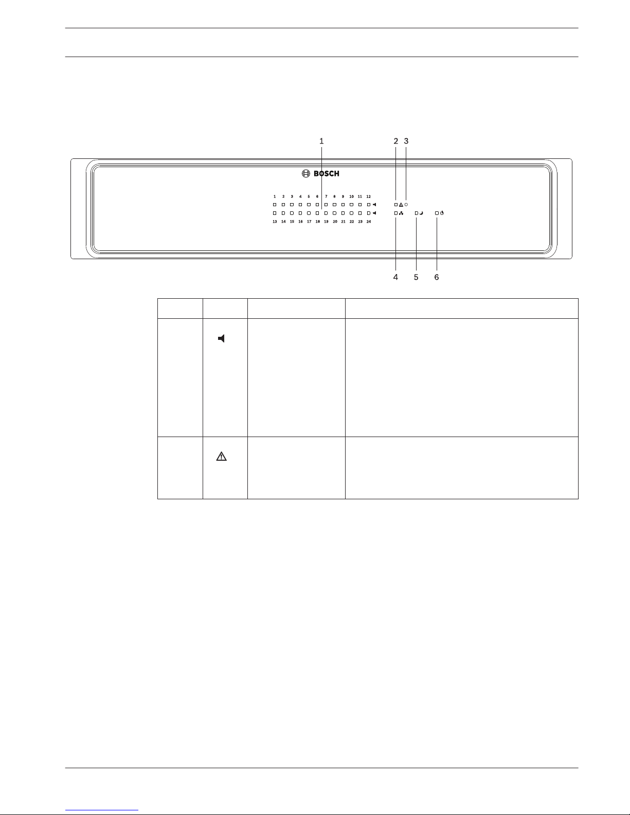
Front panel
Number Symbol Element Description
1 Zone status
indicator light
Indicates the status of the zone:
– Green = Zone is in use for non-emergency
purpose
– Yellow = Zone fault detected (Note: The
indication of this status has the highest
priority)
– Red = Zone is in use for emergency purpose
– Off = Zone in idle condition
2 General fault
warning indicator
light
This indicator lights up yellow if a fault in the
device is detected.
Note: The fault types to be indicated via this
indicator can be configured.
3
3.1
PAVIRO Router System overview | en 9
Operation manual 12-May-2015 | 03 | F01U306901
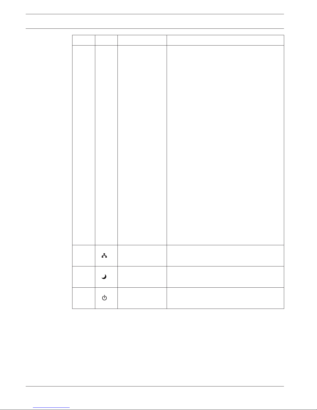
Number Symbol Element Description
3 Recessed button The button is protected to prevent it from being
pressed accidentally. Use a pointed object (such
as a ballpoint pen) to press the button.
This button has the following functions if the CAN
address of the device is not set to 00:
– Find function: If the find function of the
device is activated, press this button to
deactivate the indicators.
– Displaying the CAN baud rate: Press this
button for at least one second. Please refer to
section Displaying the CAN baud rate, page
25.
– LED test: Press this button for at least three
seconds to activate the LED test. All
indicators at the front panel light up as long
as the button is pressed.
This button has the following functions if the CAN
address of the device is set to 00:
– Resetting a fault (e.g. watchdog fault): Press
the button briefly to confirm a fault.
– Setting/displaying the CAN baud rate: Press
this button for at least one second. Please
refer to section Configuring the CAN baud rate,
page 25.
– Resetting to delivery condition: Press this
button for at least three seconds. Please refer
to section Resetting to factory default settings,
page 29.
4
Network indicator
light
This indicator lights up green if successful data
communication has been established.
5 Standby indicator
light
This indicator lights up green when the device is in
standby mode.
6 Power indicator
light
This indicator lights up green when the power
supply is OK.
10
en | System overview PAVIRO Router
12-May-2015 | 03 | F01U306901 Operation manual
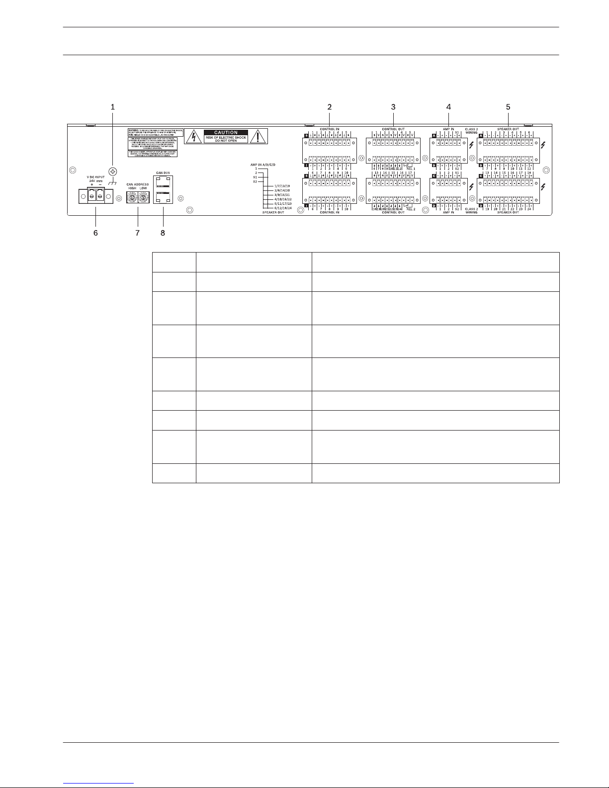
Rear panel
Number Element Description
1 Grounding screw Ground connection
2 CONTROL IN ports Control port with isolated or supervised inputs. Please
refer to section Control input, page 20.
3 CONTROL OUT ports Control port with open collector outputs. Please refer
to section Control output, page 21.
4 AMP IN ports Input for 100 V (or 70 V) audio signal from power
amplifier.
5 SPEAKER OUT ports Output for speaker zones.
6 DC power input
7 CAN ADDRESS selector
switch
HIGH-byte and LOW-byte for configuring the CAN
address of the device.
8 CAN BUS port Connection with CAN bus, e.g. controller.
3.2
PAVIRO Router System overview | en 11
Operation manual 12-May-2015 | 03 | F01U306901
 Loading...