

Bosch PVA-4CR12 Operation Manual

PAVIRO Controller
PVA-4CR12
en Operation manual


Table of contents
1
Safety 4
2
Short information 8
3
System overview 9
3.1 Rear 11
3.2 Front 13
4
Parts included 15
5
Installation 16
5.1 OM-1 Module installation 17
6
Connection 18
6.1 Audio input 18
6.1.1 Line level signal 18
6.1.2 Amplifier inputs 19
6.2 Audio output 21
6.2.1 Line level signal 21
6.2.2 Loudspeaker outputs 22
6.3 Call station 23
6.4 Ethernet 24
6.5 Supply voltage 24
6.6 CAN BUS 25
6.7 Slave clocks 27
6.8 DCF77 28
6.9 Ready relay 28
6.10 Control input 29
6.10.1 CONTROL IN 29
6.10.2 ANALOG CONTROL IN 31
6.11 Control output 32
6.11.1 CONTROL OUT 32
6.11.2 CONTROL OUT HP 34
7
Configuration 35
7.1 Network configuration 35
7.2 Displaying the CAN baud rate 35
8
Operation 37
8.1 Line supervision 37
8.1.1 Impedance measurement 37
8.1.2 EOL slave module 38
8.1.3 Plena EOL 39
8.2 Pilot tone 39
9
Maintenance 40
10
Technical data 41
10.1 Standards 43
10.2 Dimensions 44
PAVIRO Controller Table of Contents | en 3
Operation manual 08-May-2017 | 04 | F01U306900
Safety
Danger!
High risk: This symbol indicates an imminently hazardous situation such as "Dangerous
Voltage" inside the product.
If not avoided, this will result in an electrical shock, serious bodily injury, or death.
!
Warning!
Medium risk: Indicates a potentially hazardous situation.
If not avoided, this could result in minor or moderate bodily injury.
!
Caution!
Low risk: Indicates a potentially hazardous situation.
If not avoided, this could result in property damage or risk of damage to the unit.
1. Read these instructions. – All the safety and operating instructions should be read
before the apparatus or system is operated.
2. Keep these instructions. – The important safety instructions and operating instructions
should be retained for future reference.
3. Heed all warnings. – All warnings on the apparatus and in the operating instructions
should be adhered to.
4. Follow all instructions. – All instructions for installation or use/operating should be
followed.
5. Do no use this apparatus near water. – Do not use this apparatus near water or a moist
environment - for example, near a bath tub, wash bowl, kitchen sink, or laundry tub, in a
wet basement, near a swimming pool, in an unprotected outdoor installation, or any area
which is classified as a wet location.
6. Clean only with dry cloth. – Unplug the apparatus from the outlet before cleaning. Do
not use liquid cleaners or aerosol cleaners.
7. Do not block any ventilation openings. Install in accordance with the manufacturer’s
instructions. – Openings in the enclosure, if any, are provided for ventilation and to
ensure reliable operation of the apparatus and to protect it from overheating. These
openings must not be blocked or covered. This apparatus should not be placed in a builtin installation unless proper ventilation is provided or the manufacturer’s instructions
have been adhered to.
8. Do not install near any heat sources such as radiators, heat registers, stoves, or other
apparatus (including amplifiers) that produce heat or in direct sunlight.
9. No naked flame sources, such as lighted candles, should be placed on the apparatus.
10. Do not defeat the safety purpose of the polarized or ground-type plug. – A polarized
plug has two blades with one wider than the other. A grounding type plug has two blades
and a third grounding prong. The wider blade or the third prong are provided for your
safety. If the provided plug does not fit into your outlet, consult an electrician for
replacement of the obsolete outlet.
11. Protect the power cord from being walked on or pinched particularly at plug,
convenience receptacles, and the point where they exit from the apparatus.
12. Only use attachments/accessories specified by the manufacturer. – Any mounting of the
apparatus should follow the manufacturer’s instructions, and should use a mounting
accessory recommended by the manufacturer.
1
4 en | Safety PAVIRO Controller
08-May-2017 | 04 | F01U306900 Operation manual
13. Use only with the cart, stand, tripod, bracket or table specified by the manufacturer, or
sold with the apparatus. – When a cart is used, use caution when moving the cart/
apparatus combination to avoid injury from tip-over. Quick stops, excessive force, and
uneven surfaces may cause the appliance and cart combination to overturn.
14. Unplug this apparatus during lighting storms or when unused for long periods of time.
– Not applicable when special functions are to be maintained, such as evacuation
systems.
15. Refer all servicing to qualified service personnel. – Servicing is required when the
apparatus has been damaged in any way, such as power-supply cord or plug is damaged,
liquid has been spilled or objects have fallen into the apparatus, the apparatus has been
exposed to rain or moisture, does not operate normally, or has been dropped.
16. The apparatus shall not be exposed to dripping or splashing and that no objects filled
with liquid, such as vases, shall be placed on the apparatus.
17. Batteries (battery pack or batteries installed) shall not be exposed to excessive heat
such as sunshine, fire or the like.
!
Caution!
Danger of explosion if battery is incorrectly replaced. Replace only with the same or
equivalent type. Dispose of used batteries according to the environmental law and
procedures.
18. Professional installation only – Do not use this equipment in residential applications.
19. Condensation – In order to avoid condensation; wait a few hours before turning on the
equipment when it is transported from a cold to a warm space.
20. Hearing damage – For apparatus with audio output, to prevent possible hearing damage,
do not listen at high volume levels for long periods.
21. Replacement parts – When replacement parts are required, be sure the service
technician has used replacement parts specified by the manufacturer or having the same
characteristics as the original part. Unauthorized substitutions may result in fire, electric
shock or other hazards.
22. Safety check – Upon completion of any service or repairs to this apparatus, ask the
service technician to perform safety checks to determine that the apparatus is in proper
operating condition.
Danger!
Overloading – Do not overload outlets and extension cords as this can result in a risk of fire or
electric shock.
23. Power sources – This apparatus should be operated only from the type of power source
indicated on the marking label. If you are not sure of the type of power supply you plan to
use, consult your appliance dealer or local power company. For apparatuses intended to
operate from battery power, or other sources, refer to the operating instructions.
24. Power lines – An outdoor system should not be located in the vicinity of overhead power
lines or other electric light or power circuits, or where it can fall into such power lines or
circuits. When installing an outdoor system, extreme care should be taken to keep from
touching such power lines or circuits, as contact with them might be fatal. U.S.A. models
only – refer to the National Electrical Code Article 820 regarding installation of CATV
systems.
PAVIRO Controller Safety | en 5
Operation manual 08-May-2017 | 04 | F01U306900
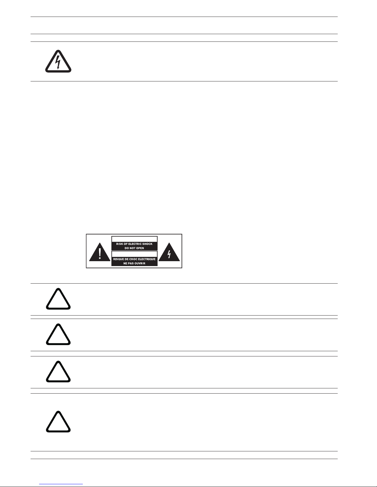
Danger!
Object and Liquid entry – Never push objects of any kind into this apparatus through
openings as they may touch dangerous voltage points or short-out parts that could result in a
fire or electric shock. Never spill liquid of any kind on the apparatus.
25. Coax grounding – If an outside cable system is connected to the apparatus, be sure the
cable system is grounded. U.S.A. models only: Section 810 of the National Electrical
Code, ANSI/NFPA No.70-1981, provides information with respect to proper grounding of
the mount and supporting structure, grounding of the coax to a discharge apparatus, size
of grounding conductors, location of discharge unit, connection to grounding electrodes,
and requirements for the grounding electrode.
26. Protective grounding – An apparatus with class I construction shall be connected to a
power outlet socket with a protective grounding connection.
Protective earthing – An apparatus with class I construction shall be connected to a
mains socket outlet with a protective earthing connection.
Note for power connections
– For permanently connected equipment, a readily operable mains plug or all-pole mains
switch shall be external to the equipment and in accordance with all applicable
installation rules.
– For pluggable equipment, the socket-outlet shall be installed near the equipment and
shall be easily accessible.
This label may appear on the bottom of the apparatus due to space limitations.
!
Caution!
To reduce the risk of electrical shock, DO NOT open covers. Refer servicing to qualified
service personnel only.
!
Warning!
To prevent fire or shock hazard, do not expose units to rain or moisture.
!
Warning!
Installation should be performed by qualified service personnel only in accordance with the
National Electrical Code or applicable local codes.
!
Warning!
Power disconnect: If the apparatus is mains powered and a power supply cord set is
provided, the disconnect device is the mains plug of the power cord set.
If an AC‑DC adapter is provided and the mains plug that is part of the direct plug‑in device,
the AC‑DC adapter is the disconnect device.
The socket outlet shall be near the apparatus and shall be easily accessible.
6 en | Safety PAVIRO Controller
08-May-2017 | 04 | F01U306900 Operation manual
!
Warning!
To avoid electric shock, do not connect safety extra-low voltage (SELV) circuits to telephone-
network voltage (TNV) circuits. LAN ports contain SELV circuits, and WAN ports contain TNV
circuits. Some LAN and WAN ports both use RJ‑45 connectors. Use caution when connecting
cables.
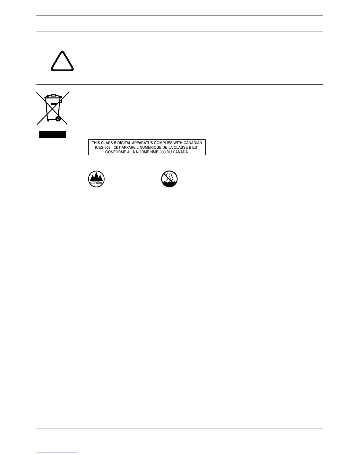
Old electrical and electronic appliances
Electrical or electronic devices that are no longer serviceable must be collected separately and
sent for environmentally compatible recycling (in accordance with the European Waste
Electrical and Electronic Equipment Directive).
To dispose of old electrical or electronic devices, you should use the return and collection
systems put in place in the country concerned.
Only used at
altitude not
exceeding 2000m.
Only used in non-
tropical climate
regions.
PAVIRO Controller Safety | en 7
Operation manual 08-May-2017 | 04 | F01U306900

Short information
The PVA-4CR12 controller is the central paging manager for the PAVIRO system. Eight local
audio inputs can be switched to four audio outputs. A two channel message manager is
integrated. The controller provides all the audio processing, supervision and control functions
for a complete PAVIRO system. A single controller supports up to 16 call stations and 492
paging zones. The controller is equipped with 12 zones, 18 GPIs and 19 GPOs. One controller
can handle up to 2000 W loudspeaker load. Additional zones and power can be added by
using up to 20 external routers and 40 amplifiers with each 2 ✕ 500 W. The zone indicator
lights on the front indicate the current status of every zone:
– Green: Zone in use for non emergency purpose
– Red: Zone in use for emergency purpose
– Yellow: Zone fault detected
– Off: Zone in idle condition
2
8 en | Short information PAVIRO Controller
08-May-2017 | 04 | F01U306900 Operation manual

System overview
This chapter explains the basic features of the PAVIRO system and its most important
functions.
General overview
The PVA-4CR12 is the controller of the PAVIRO system. The controller contains all necessary
audio functions and is responsible for controlling and monitoring the complete PAVIRO
system. The type and number of connected audio sources, amplifiers, and relays are extremely
variable, and can be adjusted to individual requirements. A single controller can manage up to
16 call stations and up to 492 loudspeaker zones. Control inputs and outputs can be used for
controlling and monitoring functions. Both logic level and the analog level signals can be
processed. Configuration is performed on a PC using the IRIS-Net software, which also
provides access to system documentation and the required user interface. A configuration can
be changed at any time, and adjusted to new circumstances without having to modify the
system installation. A PC is required only for loading or changing the configuration; it does not
need to be connected during live operation. In many cases, however, a permanently connected
PC is helpful; for example, to provide detailed status displays and log reports, real-time
loudspeaker and sound control, or for remote diagnosis and maintenance via the network. The
user interface can be individually tailored, and up to 32 password levels can be assigned.
Audio routing
A digital audio matrix is integrated into the controller. Up to 8 local audio inputs, 2 message
playback channels, and 4 internal generators are available. The 4 audio output channels are
connected to the amplifiers via a 4-channel audio bus. The amplifiers include an audio input
router where the correct input signal is selected automatically. Each loudspeaker circuit can
be connected with amplifier outputs via a relay matrix, which allows for 492 loudspeaker
zones. The controller manages the audio signals, and distributes them according to priority. In
addition to the call stations, other audio sources can also be connected to the audio inputs
such as microphones, mixing desks, CD players, MP3 players, tuners, and so on. A number of
different connections are available for optimum adjustment.
Audio processing
The controller provides separate volume controls with a mute function for each audio input
and audio output. Each audio input has a 3-band equalizer and a compressor for optimal
sound adjustment of the audio sources. All outputs are fitted with a 5-band equalizer and a
limiter. For the equalizers, the operator can select from five different filter types for each band
filter (peak, low-shelving, high-shelving, high pass, low pass). Volume levels, filter parameters,
and so on are set on the PC during configuration. However, these can also be changed in realtime during operation using the graphical user interface, the special keys for the call stations,
or external operating controls.
Signal generators
The controller provides four signal generators: Two independent generators for generating
alarm signals and two independent generators for generating chime signals. Operators can
choose between 24 alarm types and six chime types that are available ex-works.
Message manager
The integrated message manager is for EVAC messages and alarm signals, as well as
commercial messages and chime/pre-chime signals. The message manager allows easy
configuration of EVAC and commercial messages, and other customized audio signals by using
the IRIS-Net software.
3
PAVIRO Controller System overview | en 9
Operation manual 08-May-2017 | 04 | F01U306900

Call stations
The call stations are used mainly for announcements, but are also used for manual control of
the PAVIRO system. Possible call station functions include zone/group selection,
announcements, program allocation, triggering chime and alarm signals, and message
playback. However, special commands such as volume control, light control, function displays,
and much more are also possible. The call stations can therefore also be configured for
general control tasks. If an announcement is to be routed through a loudspeaker zone that is
already occupied, the system issues an occupied notification (i.e., the talk button indicator
light flashes). If the call station concerned has a higher priority, it can interrupt the lowerpriority call from the other call station/signals. The system is configured to indicate the
conditions: The user is notified that the system is occupied when selecting the zone/group
(before the interruption) by the flashing talk button indicator light. The user can now decide
whether to interrupt the signal immediately, or whether to wait until the end of the active
announcement. Each zone selection key has two indicator lights: A green indicator light shows
the current selection, and a red indicator light shows if the zone is occupied with an
emergency signal. System information or error messages can be displayed on the call station's
illuminated graphic display.
Control inputs and outputs
The PAVIRO system has analog and logic control inputs and logic control outputs. The control
inputs allow a connection to be established to fire alarm systems, intruder alarm systems, or a
control desk. However, it is also possible to connect external switches, controllers, or rotary
potentiometers, or triggers from external equipment (power supply, power amplifiers, and so
on). The control outputs allow the user to activate/deactivate external devices, trigger signals
and events, remotely control doors, gates, and roller blinds, and much more.
Automatic control
The controller contains a quartz-controlled real-time clock that can be switched to DCF77
radio clock operation via an optional antenna. The system clock automatically recognizes leap
years; in DCF77 mode, it also automatically switches to daylight-saving time. Up to 80 external
slave clocks (max. 1 A) can be controlled by the system clock. A special output for polarity
switching pulse, which is protected against short circuits, is integrated in the controller for
this purpose. Slave clocks are automatically adjusted if a time difference between the slave
clocks and the system clock is detected, for example after a power failure or in the event of
manual input. Together with the calendar function, the system clock can be used to execute
functions such as a break chime, music, gate control, light control, and so on. These functions
can be programmed for specific days, but can also be implemented on an hourly, daily,
weekly, monthly, and annual basis. Up to 500 time-controlled events can be entered.
Functions and parameters can be connected in an internal sequence. The TaskEngine in the
controller GUI provides a graphic way to combine processes individually. One example would
be a chime signal to be transmitted at a certain volume and with a specific priority in specific
call groups, and which simultaneously activates a control output. In this case, the process
consists of the “chime” and “analog output” function blocks combined with the parameters of
chime type, volume, priority number, call group number, as well as the type and number of the
control output. The processes can be triggered via special function keys on the call stations or
via control inputs, but can also be linked to clock or calendar dates.
Interfaces
In addition to the control inputs and outputs, the PAVIRO system also includes other
interfaces:
– The call stations are connected to the controller via the CST bus (CAN bus standard). Up
to four call stations can be connected via one CST bus.
10
en | System overview PAVIRO Controller
08-May-2017 | 04 | F01U306900 Operation manual
– The power amplifiers and the routers are controlled and monitored by the controller via
an additional, independent CAN bus interface.
– The connection to a PC is established via an Ethernet interface.
– An optional OM-1 Module can be installed at the rear of the device.
The OM‑1 is a compact interface module which is prepared for a connection to an OMNEO
network. It can send and receive Dante audio to and from up to four other PAVIRO controllers
with an OM‑1 Interface Module.
Monitoring
The controller monitors all internal functions itself, and the connected call stations, routers
and power amplifiers including their connection lines are also monitored by polling and pilot
tone. Loudspeaker lines can be monitored by impedance measurement or end-of-line modules
installed at the last speaker. The PAVIRO system also supports emergency power operation –
in the event of a power failure, the controller can assume all power management functions,
that is, all unnecessary internal and external consumers switch to standby mode, or are
deactivated and only reactivated again when required. This greatly reduces power
consumption, and ensures maximum operating time on battery power. Error messages can be
displayed on the call station displays in plain text. The status of the “combined fault” is
available via the floating READY contact on the controller.
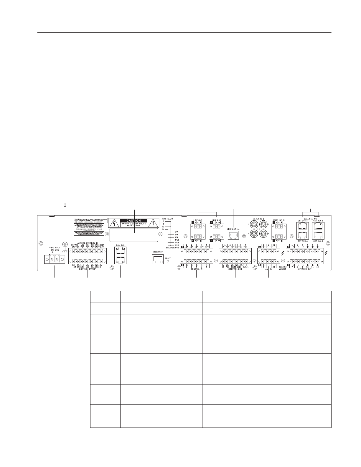
Rear
2
3 4 5 6 7
8 9 10 11 12 13 14 15 16
Number Element Description
1 Grounding screw Ground connection
2 Blind cover for optional OM-1
Module
Blind cover with slot for installing OM-1 Module.
3 LINE OUT 1-4 ports
(Euroblock)
Balanced line level audio outputs for channel 1
to 4 (parallel to RJ-45 port).
4 LINE OUT 1-4 port (RJ-45) Balanced line level audio output for channel 1 to
4 (parallel to Euroblock port).
5 AUX IN 1/2 ports (RCA) Stereo audio input for line level signals.
6 MIC/LINE IN 1/2 ports
(Euroblock)
Audio input for microphone or line level signals.
7 CST BUS 1-4 ports (RJ-45) Ports for connecting call stations.
8 DC power input
3.1
PAVIRO Controller System overview | en 11
Operation manual 08-May-2017 | 04 | F01U306900

Number Element Description
9 CONTROL IN/OUT port Control port with analog/logic inputs, high
power outputs and pins for DCF77 or slave
clocks.
10 CAN BUS port Port for connecting power amplifiers or routers.
11 ETHERNET port with status
indicator lights
Port for connecting to a PC or other network
devices.
12 Reset button Reset of the device: Briefly press this button to
reset the device.*
13 CONTROL IN port Control port with isolated or supervised inputs.
14 CONTROL OUT port Control port with open collector outputs.
15 AMP IN port Input for 100 V (or 70 V) audio signal from power
amplifier.
16 SPEAKER OUT port Output for speaker zones.
* If the reset button is pressed too long (e.g. > 4 seconds), the device enters the service
mode. Press the reset button again to exit the service mode.
12
en | System overview PAVIRO Controller
08-May-2017 | 04 | F01U306900 Operation manual
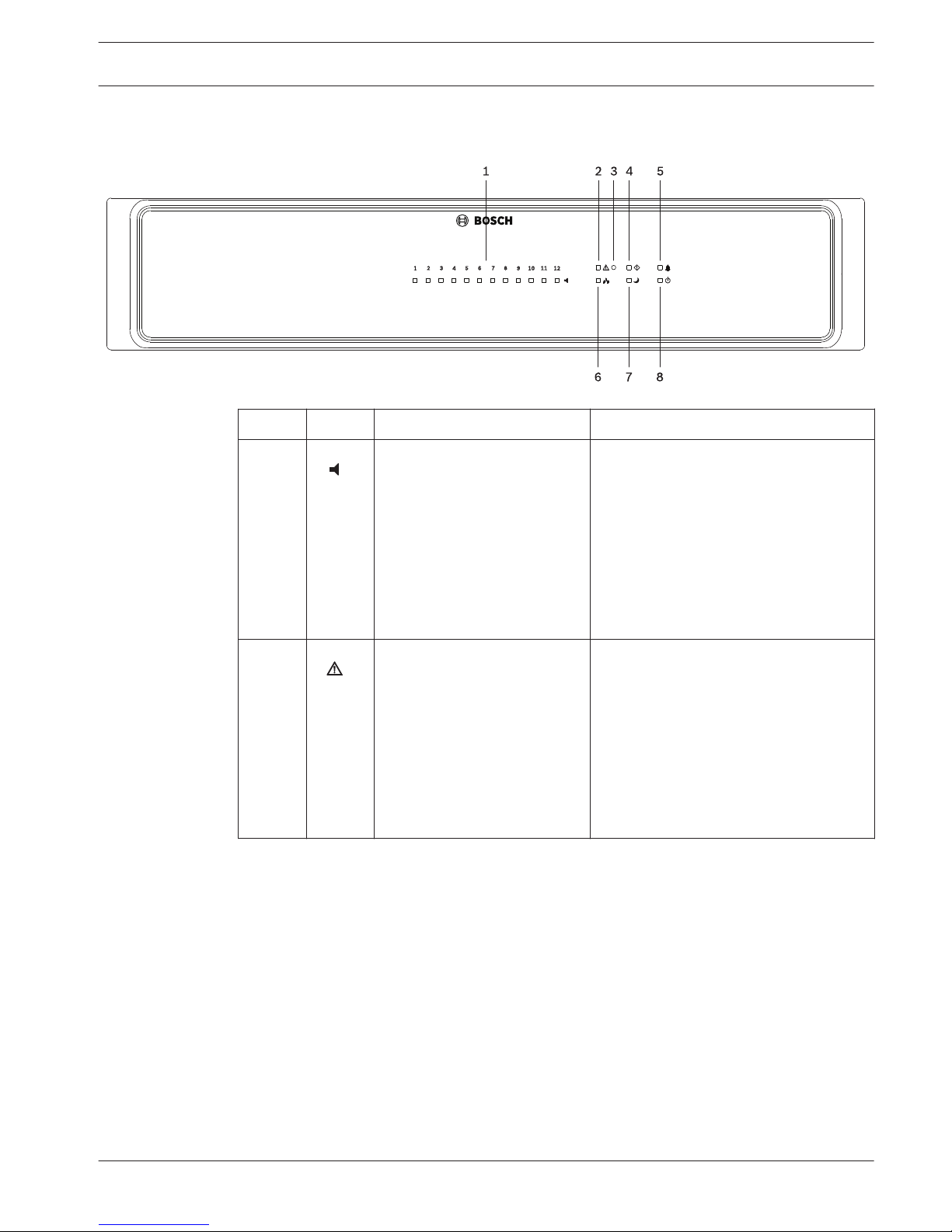
Front
Number Symbol Element Description
1 Zone status indicator light Indicates the status of the zone:
– Green = Zone is in use for non-
emergency purpose
– Yellow = Zone fault detected (Note:
The indication of this status has the
highest priority)
– Red = Zone is in use for emergency
purpose
– Off = Zone in idle condition
2 Combined fault warning
indicator light
This indicator lights yellow if a fault in
the system is detected. The indicator is
coupled with the READY contact (see
section Ready relay, page 28) on the
rear of the device, which allows any
faulty system behavior to be reported
externally.
Note: The fault types to be indicated via
this indicator can be configured.
3.2
PAVIRO Controller System overview | en 13
Operation manual 08-May-2017 | 04 | F01U306900
Number Symbol Element Description
3 Recessed button The button is protected to prevent it
from being pressed accidentally. Use a
pointed object (such as a ballpoint pen)
to press the button.
This button has the following functions:
– Silencing of the buzzer: If the
buzzer is active, press the button
briefly to deactivate the warning
tone.
– Find function: If the find function of
the device is activated, press this
button to deactivate the indicators.
– Displaying the CAN baud rate: Press
this button for at least one second.
Please refer to section Displaying
the CAN baud rate, page 35
– Indicator test: Press this button for
at least three seconds to activate all
indicators. All indicators (LEDs) at
the front panel light up as long as
the button is pressed (“LED test”)
and the internal buzzer is activated.
4
System fault indicator light This indicator lights yellow if a system
fault according EN 54-16 was detected.
5 Voice alarm indicator light This indicator lights red if the controller
is in voice alarm state according EN
54-16.
6 Network indicator light Indicates the Ethernet network status:
– Illuminated green: Successful data
communication to all configured
Ethernet devices has been
established.
– Flashing green: Ethernet connection
to at least one Ethernet device lost.
– Off: No Ethernet connection.
7 Standby indicator light This indicator lights up green when the
device is in standby mode.
8 Power indicator light This indicator lights up green when the
power supply is OK.
14
en | System overview PAVIRO Controller
08-May-2017 | 04 | F01U306900 Operation manual
 Loading...