How it Works
Log In / Sign Up
Buy Points
How it Works
FAQ
Contact Us
Questions and Suggestions
Users
Bosch
Loading...
N
NIN-73023-A3A
4
NIN-73023-A3AS
4
NIN-733
3
NIN-733 FW5.7
NIN-733-V03IP
3
NIN-733-V03IPS
2
NIN-733-V03P
2
NIN-733-V03PS
2
NIN-733-V10IP
2
NIN-733-V10IPS
4
NIN-733-V10P
2
NIN-733-V10PS
2
NIN-832
3
NIN-832 FW5.7
NIN-832-V03IP
NIN-932
3
NIN-932 FW5.7
NIN-932-V03IP
NIN-DMY
2
NIR-50850
NIR-50850-MRP
NIR-50940
NIR-50940-MRP
NIT3065
3
NIT3065UC
5
NIT3065UC/01
NIT5065
3
NIT5065UC
4
NIT5065UC/01
2
NIT5065UC/20
2
NIT5065UC/21
2
NIT5066UC
4
NIT5066UC/01
2
NIT5068UC
8
NIT5068UC/01
2
NIT5469UC
3
NIT5665
3
NIT5665UC
6
NIT5665UC/01
NIT5666UC
5
NIT5666UC/01
2
NIT5668UC
7
NIT5668UC/01
2
NIT8053UC
3
NIT8053UC/01
2
NIT8053UC/08
2
NIT8065
3
NIT8065UC
9
NIT8065UC/01
2
NIT8065UC/20
2
NIT8065UC/21
2
NIT8065US
NIT8066SUC
6
NIT8066SUC/01
2
NIT8066UC
6
NIT8066UC/01
2
NIT8068SUC
5
NIT8068SUC/01
2
NIT8068UC
6
NIT8068UC/01
2
NIT8069SUC
7
NIT8069UC
7
NIT8653UC
3
NIT8653UC/01
2
NIT8653UC/08
2
NIT8655
2
NIT8665
NIT8665UC
10
NIT8665UC/01
2
NIT8665UC/02
2
NIT8665UC/20
2
NIT8665UC/21
2
NIT8666SUC
5
NIT8666SUC/01
2
NIT8666UC
5
NIT8666UC/01
2
NIT8668SUC
7
NIT8668SUC/01
2
NIT8668UC
6
NIT8668UC/01
2
NIT8669SUC
6
NIT8669UC
6
NITP066SUC
4
NITP066UC
4
NITP066UC/01
2
NITP068SUC
6
NITP068SUC/01
2
NITP068UC
6
NITP068UC/01
2
NITP069SUC
4
NITP069UC
4
NITP666SUC
6
NITP666SUC/01
2
NITP666UC
6
NITP666UC/01
2
NITP668SUC
6
NITP668SUC/01
2
NITP668UC
6
NITP668UC/01
2
NITP669SUC
4
Loading...
Loading...
Nothing found
NIT8065UC/21
Installation Guide
36 pgs
1.6 Mb
0
Owner’s Manual
104 pgs
7.83 Mb
0
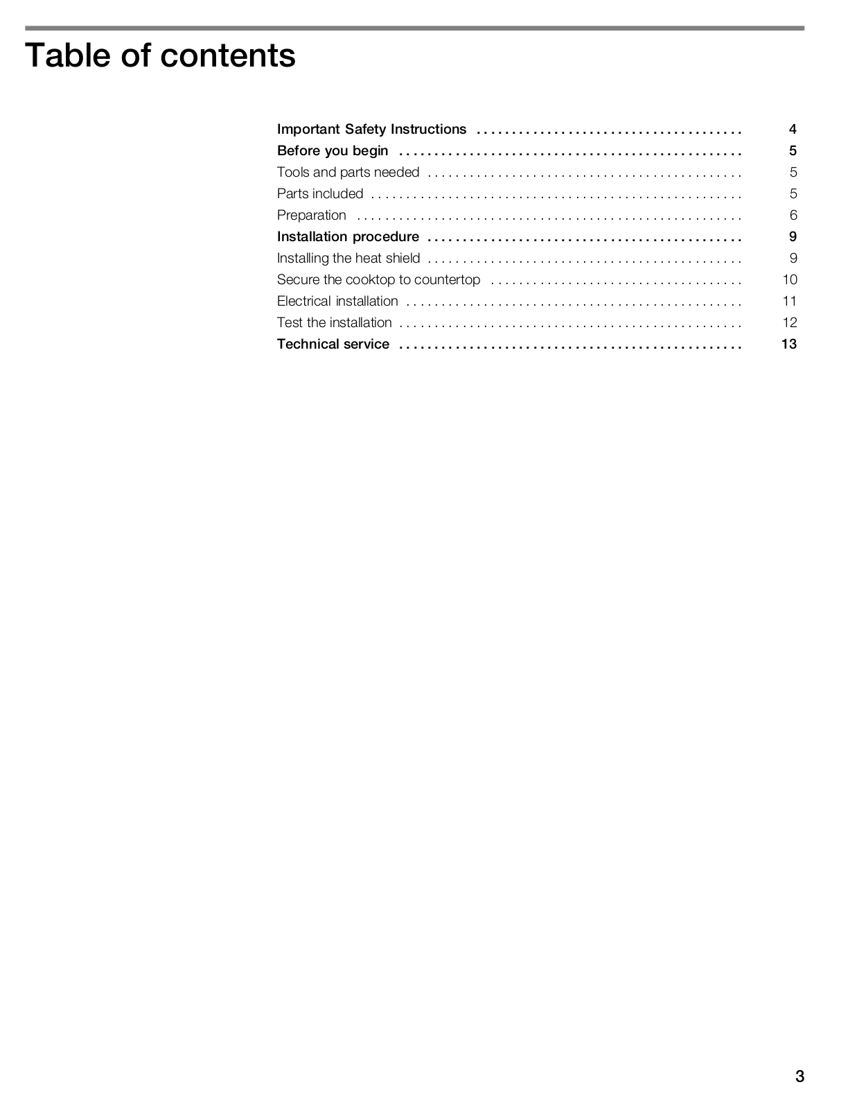
Table of contents
Loading...
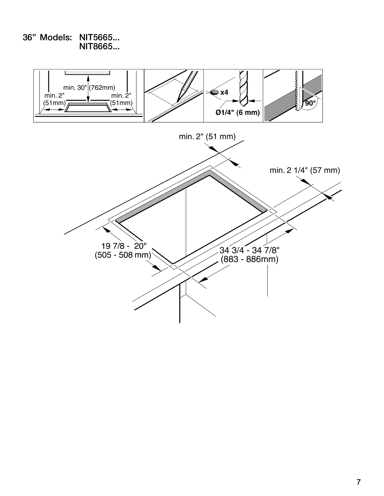
Bosch NIT8065UC/21, NIT5065UC/21 Installation Guide
...
Bosch Installation Guide
Download
Specifications and Main Features
Frequently Asked Questions
User Manual
Download
Loading...
+
25
hidden pages
Unhide
You need points to download manuals.
1 point = 1 manual.
You can buy points or you can get point for every manual you upload.
Buy points
Upload your manuals
 Loading...