

Bosch NGM5455UC Installation Manual
LP Gas Conversion Kit
Installation Manual
NGM Gas Cooktops
NGM5455UC


Table of Contents
Questions?
1-800-944-2904
www.bosch-home.com/us
We look forward to hearing from you!
This Bosch Appliance is made by
BSH Home Appliances Corporation
1901 Main Street, Suite 600
Irvine, CA 92614
Safety Definitions . . . . . . . . . . . . . . . 1
NGM Gas Cooktop LP Gas Conversion . . . . . . . . 3
Preparation . . . . . . . . . . . . . . . . . . . . 3
Installation Procedure . . . . . . . . . . . . 4
Checklist. . . . . . . . . . . . . . . . . . . . . . . . . . . . . 4
Step 1 - Convert the Pressure Regulator . . . . 4
Step 2 - Replace the Orifices . . . . . . . . . . . . . 5
Step 3 - Replace the Burner Caps and Grates 6
Step 4 - Convert Valves for LP Gas . . . . . . . . 6
Test for Gas Leaks . . . . . . . . . . . . . . . . . . . . . 6
Check Manifold Gas Pressure . . . . . . . . . . . . 7
Final Check. . . . . . . . . . . . . . . . . . . . . . . . . . . 7
Before Calling Service . . . . . . . . . . . . . . . . . . 7

9 IMPORTANT SAFETY INSTRUCTIONS
WARNING:
If the information in this manual is not followed exactly, a
fire or explosion may result causing property dama ge ,
personal injury or death.
-- Do not store or use combustible materials,
gasoline or other flammable vapors and liquids
in the vicinity of this or any other appliance.
-- WHAT TO DO IF YOU SMELL GAS
• Do not try to light any appliance.
• Do not touch any electrical switch.
• Do not use any phone in your building.
• Immediately call your gas supplier from a
neighbor’s phone. Follow the gas supplier’s
instructions.
• If you cannot reach your gas supplier, call
the fire department.
-- Installation and service must be perf ormed by a
qualified installer, authorized service agency or
the gas supplier.
READ AND SAVE THESE INSTRUCTIONS
Safety Definitions
9 WARNING
This indicates that death or serious injuries may
occur as a result of non-observance of this warning.
9 CAUTION
This indicates that minor or moderate injuries may
occur as a result of non-observance of this warning.
NOTICE: This indicates that damage to the appliance or property may occur as a result of non-compliance with this
advisory.
Note: This alerts you to important information and/or tips.
Gas Appliance Safety
9001070927 Rev A English 1
9 IMPORTANT SAFETY INSTRUCTIONS
READ AND SAVE THESE INSTRUCTIONS
BOSCH COOKTOP CONVERSION KIT FOR
TRADITIONAL MODELS NATURAL GAS (NG) TO
PROPANE (LP) GAS
This kit is used to convert only NGM sealed burner
cooktops from natural gas operation to pr op a ne gas
operation. This kit cannot be used to convert other Bosch
model sealed burner cooktops, ranges, or any other brand
of cooktops.
WARNING
This conversion kit shall be installed by a qualified
service agency in accordance with the manufacturer’s
instructions and all applicable codes and requir em e nts
of the authority having jurisdiction. If the information in
these instructions is not followed exactly, a fire,
explosion or production of carbon monoxide may result
causing property damage, personal injury or loss of life.
The qualified service agency is responsible for the
proper installation of this kit. The installation is not
proper and complete until the operation of the converted
appliance is checked as specified in the manufacturer’s
instructions supplied with the kit.
CAUTION
When connecting the unit to the propane gas, make
certain the propane gas tank is equipped with its own
high pressure regulator. In addition, a pressure
regulator was supplied with the cooktop. This second
regulator must be installed with the cooktop. The
maximum gas pressure to this appliance is not to
exceed 14.0 inches water column from the propane gas
tank regulator.
The following must be met when testing supply piping
system:
a) The appliance and its individual shut-off valve must
be disconnected from the gas supply piping system at
test pressures in excess of 1/2 psig (3.5 kPa).
b) The appliance must be isolated from the gas supply
piping system by closing its individual manual shut-off
valve during any pressure testing of the gas supply
piping system at test pressures equal to or less than 1/2
psig (3.5 kPa).
IMPORTANT: Only a qualified service technician or
installer should make this conversion
INSTALLER: Please leave these Conversion Instructions
with this unit for the owner.
OWNER: Please retain these instructions for future
reference.
For Massachusetts Installations:
1. Installation must be performed by a qualified or
licensed contractor , plumber , or gas fitter qualified or
licensed by the state, province or region.
2. Shut-off valve must be a “T” handle gas cock.
3. Flexible gas connector must not be longer than 36
inches.
English 2 9001070927 Rev A

NGM Gas Cooktop LP Gas Conversion
flat blade
screwdriver,
small thin
blade
7mm socket
driver (3 inch
minimum
extension
adjustable
wrench and/
or slip joint
pliers
Preparation
Installation Kit Contents
Component Quantity
Conversion Kit Instructions 1
Conversion Sticker 1
Foam Tape 1
70 Orifice 2
81 Orifice 1
99 Orifice 1
Tools Required
Main Orifices
NGM5455UC BTU/hr
70 Front Right 5,000
70 Front Left 5,000
81 Rear Left 7,000
99 Rear Right 10,000
9001070927 Rev A English 3
Installation Procedure
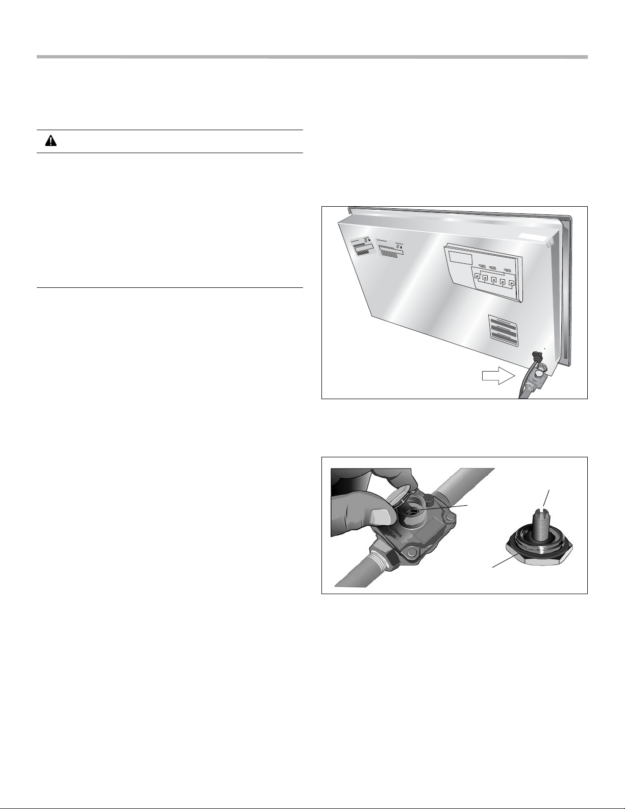
spring
gasket
plastic
button stem
This conversion process adjusts the flow of gas to the
burners to accommodate an LP gas fuel source.
CAUTION
TURN OFF GAS AND ELECTRICITY.
If the cooktop is installed in the counter,
1) shut off the gas valve for the gas supply line to
the cooktop.
2) remove the cooktop power cord from the
electrical outlet or turn off the breaker a t the b reaker
box.
3) turn all control knobs to the “Off”position.
Checklist
Each of the following steps must be completed
correctly for the appliance to function properly.
Check off each step as it is finished.
__ Step 1 - Convert the pressure regulator to use LP gas.
__ Step 2 - Remove the grates and burner caps. Remove
the Natural Gas (NG) orifices and replace them with
the LP gas orifices supplied with this kit.
__ Setp 3 - Replace the burner caps and grates
__ Step 4 - Adjust the unit valves to LP settings.
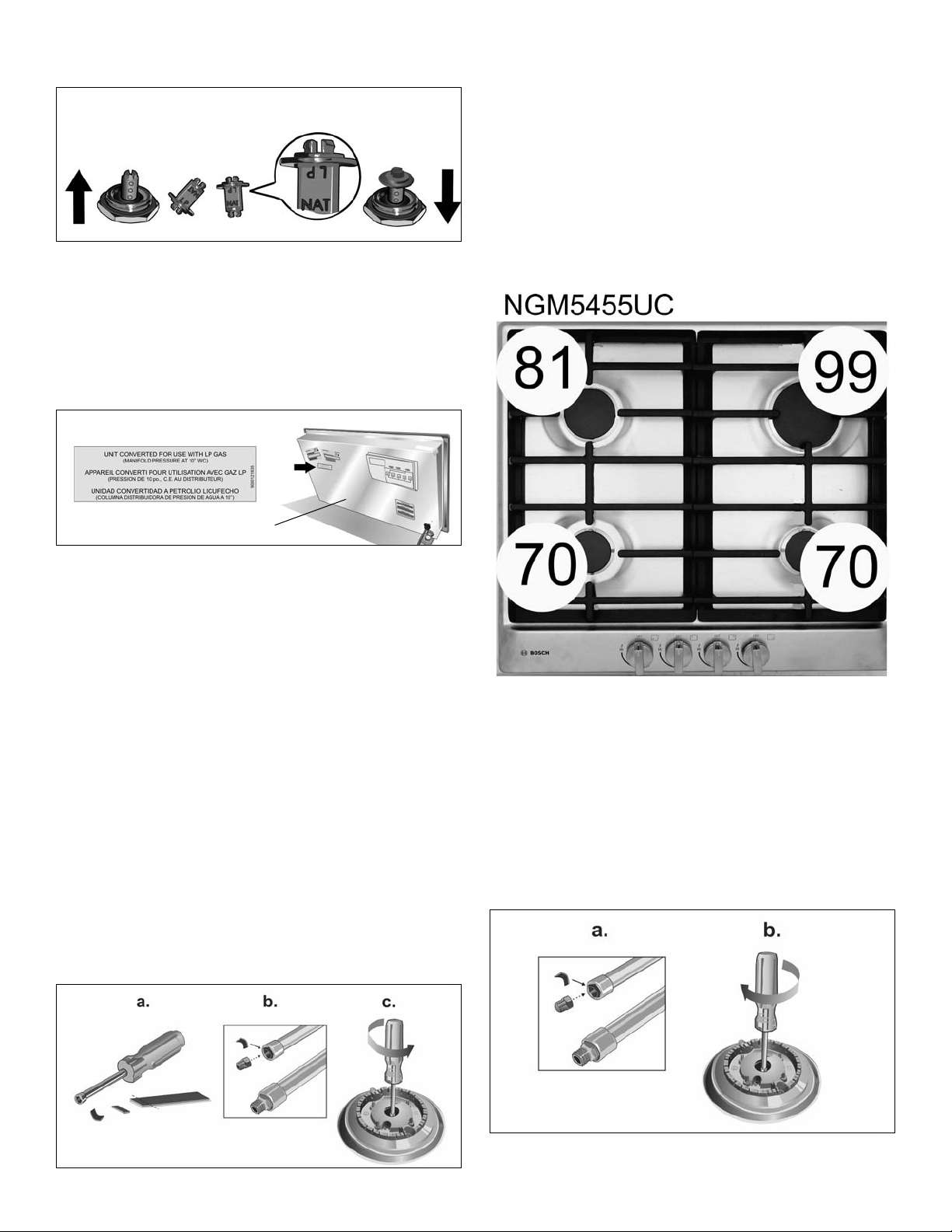
Step 1 - Convert the Pressure Regulator
Locate the pressure regulator on the bottom right end of
the cooktop.
Note: The arrow on the back of the regulator must point
in the direction of the gas flow to the cooktop.
.
Remove the hexagon shaped cap from the regulator
making sure not to dislodge the gasket on the cap or the
spring inside the regulator.
.
Grasp the plastic button stem (stem) firmly and pull it
forcefully from the metal cap. The stem snaps snugly into
an indent in the cap and may require a strong pull to
remove. (Hint: it may be helpful to gently “rock” the plastic
stem while pulling it from the metal cap.”)
After removing the stem from the cap, rotate th e stem 180°
English 4 9001070927 Rev A
so the button end of the stem is away from the cap and the
letters “LP” on the stem are upside down when the cap is
set flat on its head. Snap the stem back in place in this
position inserting it into the indent in the metal cap.The
stem should snap into place.
Natural
Gas
LP
Gas
bottom of cooktop
Important - Attach the metallic sticker (included with this
conversion kit) to the bottom of the appliance as shown,
placing it near the appliance data plate (shows model
number and information about the appliance). This sticker
provides notice that the appliance has been converted for
use with LP gas.
.
Save the NG orifices in case there is need later to restore
the appliance to use natural gas again.
4. Identify the correct placement of the LP gas orifices as
layed out on the orifice package card.
The orifice sizes are shown in the white circles
corresponding to each burner as shown in the image
below. These n umbers are engraved on the top of each
orifice. It is very important to install the correct orifice
size for each burner.
Step 2 - Replace the Orifices
1. Remove the grates and burner caps.
Note: Do not remove the ignitor from the unit.
2. Remove the orifices.
Note: The orifices require a 7 mm socket driver for
removal/replacement. The driver will need to be
inserted approximately 2 1/2” (64 mm) into the
burner cavity to reach the orifice.
Hint: To reduce the chance of the orifice being dropped
from the socket driver , add a piece of foam tape or
adhesive tape inside the socket.
a) Trim a small piece of the foam tape provided with
this kit (about 1/4” x 1/2”; 6mm x 12mm).
b) Fit this so the tape wraps against one side of the
socket so it stays in place.
c) When pressing the socket driver onto the orifice,
the tape will fit to the orifice and help prevent the
orifice from falling out of the socket during
extraction.
5. Insert each of the LP gas orifices provided with this kit
into the socket (using the small piece of foam tape to
assure a tight fit).
a) Check to be sure the small piece of foam tape used
earlier is fitted to wrap against one side of the
socket.
b) When pressing the socket driver onto the orifice,
the tape will help the orifice fit more snugly inside
the socket. This will help prevent the orifice from
falling out of the socket during insertion.
This will help prevent the orifice from falling out of the
socket during insertion.
9001070927 Rev A English 5
Step 3 - Replace the Burner Caps and
a. Hollow Stem
b. Solid Stem
Grates
Replace the grates and burner caps. Be sure the
grates are correctly placed and the rubber feet on the
grates engage the indents in the cooktop for proper
position.
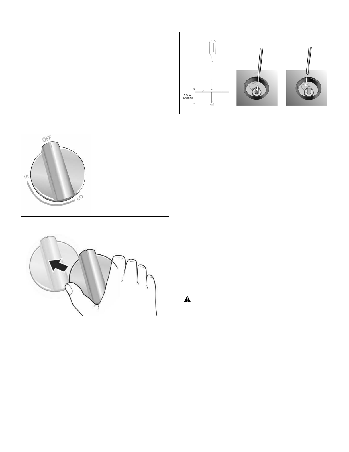
Step 4 - Convert Valves for LP Gas
The bypass jet on each valve must be adjusted. Your
cooktop may come with either hollow or solid valve shafts.
Determine the bypass screw location accordingly.
1. Turn all knobs to the “Off” position.
2. Remove knobs.
a) Hollow stem valve - insert a long, thin flat blade
screwdriver in the hollow stem of the valve. The
adjustment screw is approximately 1 1/2” (39 mm)
from the top of the stem. The screwdriver slides
through a thin rubber barrier in the stem (helps
prevent damage in the case of a spill on the unit
surface).
b) Solid stem valve - insert a long, thin flat blade
screwdriver through the seal in the area shown.
4. Engage the tip of the screwdriver into the adjustment
screw by slowly turning the screwdriver and feeling for
the blade to engage the screw . Then turn the screw
clockwise about 70 degrees (less than 1/4 turn) until it
“bottoms out” (does not turn any furthe r). The s cre w
does not take much pressure to turn. Stop when the
screw does not easily turn any further. Repeat for each
valve until all have been adjusted correctly.
5. Replace the knobs.
Your appliance will have either a) hollow stem valves, or b)
solid stem valves. The location of the adjustment screw is
determined by which type of valve your appliance has.
3. Locate the correct point of insertion for the long, thin
flat blade screwdriver to adjust the bypass jet (see the
following illustration).
Test the Installation
Test for Gas Leaks
WARNING
NEVER TEST FOR GAS LEAKS USING A FLAME.
If any leaks are detected, do not proceed past this
step until all leaks have been eliminated.
Leak testing is to be conducted by the installer according to
the instructions given in this section.
Turn on gas. Apply a non-corrosive leak detection fluid to
all joints and fittings in the gas connection between the
shutoff valve and the cooktop. Include gas fittings and
joints in the cooktop if connections may have been
disturbed during installation. Bubbles appearing around
fittings and connections indicate a leak. An electronic Gas
Leak Detector can also be used.
If a leak appears, turn off the supply line gas shutoff valve
and tighten the leaking connections. Retest for leaks by
turning on the supply line gas shutoff valve. When the leak
English 6 9001070927 Rev A
check is complete (no bubbles appear), the test is
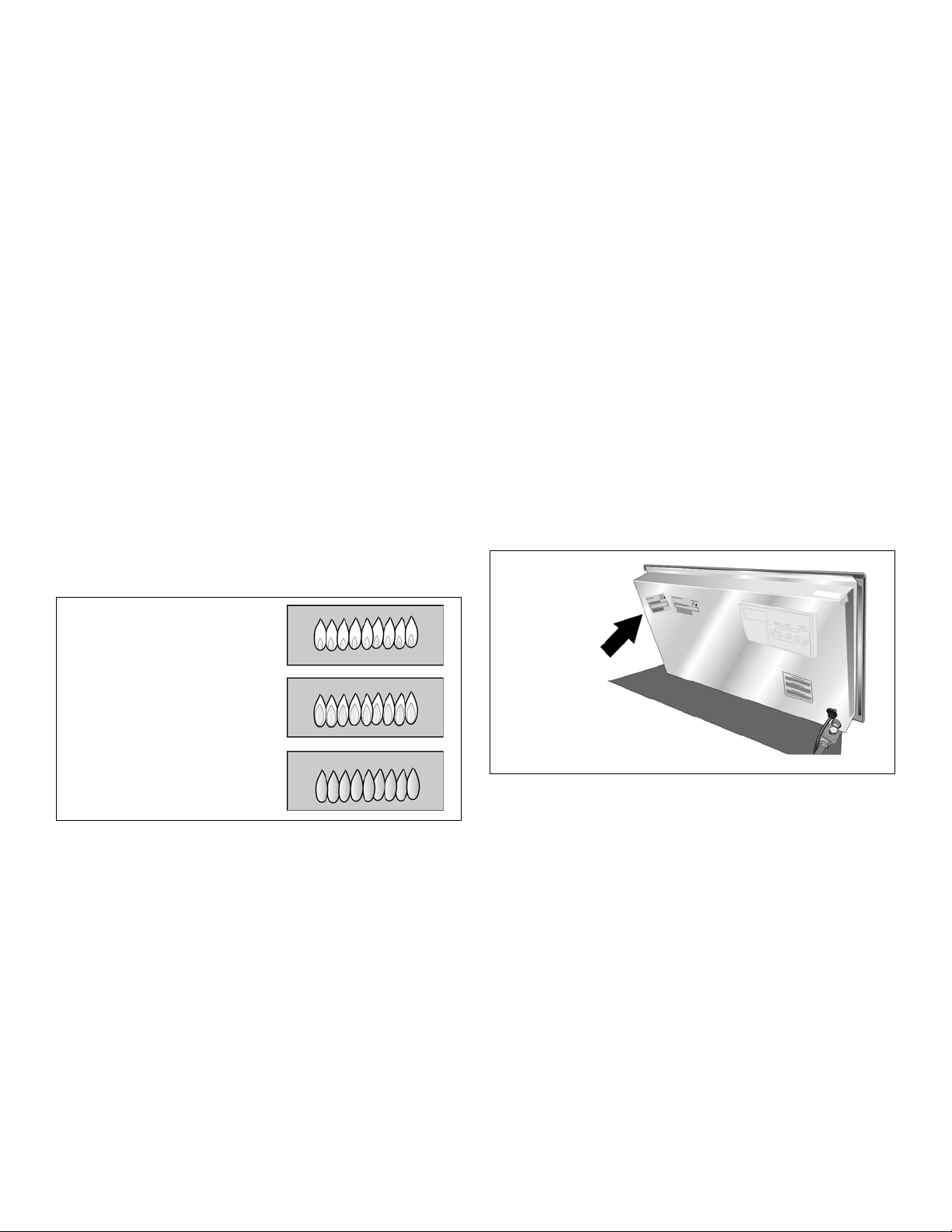
Yellow flames:
Further adustment required.
Yellow tips on outer
cones:
Normal for LP Gas.
Soft blue flames:
Normal for Natural Gas.
Product
Data Plate
complete. Wipe off all detection fluid residue.
Service
Check Manifold Gas Pressure
During any pressure testing of the gas supply piping
system at test pressures greater than 14" of water column
pressure (approximately ½" psig,
disconnect the cooktop and its individual shut-off valve
from the gas supply piping system.
If it should be necessary to check the manifold gas
pressure, connect a manometer (water gauge) or other
approved gas pressure reading device to the top burner
right rear orifice. Using a rubber hose with inside diameter
of approximately 1/4" hold tubing down tight over orifice.
Turn burner valve on.
3.5 kP A
) it is necessary to
Final Check
After conversion is complete, place each correct sized
burner cap in its seated, notched position and check the
operation of the electric igniters. Check flame
characteristics. Flame should be blue with a minimal yellow
tip on the outer cone of the flames.
Check Flame Characteristics
Before Calling Service
See your appliance Use and Care Manual for
troubleshooting information. Refer to the Warranty section
in the Use and Care Manual for warranty related
information.
To reach a service representative, see the contact
information at the front of the manual. Please be prepared
to provide the information printed on your product data
plate when calling (model, serial (FD) number, etc.).
Product Data Plate
The data plate shows the model and serial number. Refer
to the data plate on the appliance when requesting service.
The data plate is located on the bottom of the rough-in box,
underneath the visible part of the installed cooktop.
This data plate information is also provided in a sticker
attached to the product registration card shipped with your
appliance.
Keep your purchase invoice and any other relat ed
documents for warranty validation in the event service is
needed.
Note: If the flame is mostly yellow, verify that the regula-
tor is set for the correct fuel. If adjustment is necessary, retest the system.
Some yellow streaking in the flame is normal during the
initial start-up. Allow the unit to operate 4 to 5 minutes and
then re-evaluate before making further adjustments.
9001070927 Rev A English 7

English 8 9001070927 Rev A
 Loading...