

Bosch AUTODOME IP 4000 HD, NEZ-4112-PPCW4, NEZ-4212-PPCW4, NEZ-4112-CPCW4 Installation Manual
AUTODOME IP 4000 HD
NEZ-4112-PPCW4 │ NEZ-4212-PPCW4 │ NEZ-4112-CPCW4
en
Installation Manual


AUTODOME IP 4000 HD Table of contents | en 3
Bosch Security Systems Installation Manual 2015.11 | 1.1 |
Table of contents
1
Safety 5
1.1 About this Manual 5
1.2 Legal Information 5
1.3 Safety Precautions 5
1.4 Important Safety Instructions 6
1.5 Connection in Applications 7
1.6 Important Notices 7
1.7 Customer Support and Service 8
2
Introduction 10
2.1 Parts List 10
3
System Overview 11
4
Mounting Accessories 12
5
Installation Overview 13
5.1 Prepare Wiring 13
5.2 Prepare the Camera 13
6
Installing a microSD card (optional) 15
7
Installing an In-Ceiling Camera in a Drywall Ceiling 17
7.1 Tools Required 17
7.2 Installation Requirements 17
7.3 Preparing the Ceiling for Installation 17
7.4 Securing the Camera to the Ceiling 17
8
Installing an In-ceiling Camera in a Suspended Ceiling 20
8.1 Tools Required 20
8.2 Installation Requirements 20
8.3 Prepare Suspension Ceiling for Installation 20
8.4 Securing the Camera to the Ceiling 21
9
Installing a Surface Mount and Camera 24
9.1 Tools Required 24
9.2 Installation Requirements 24
9.3 Preparing the Surface Mount for Installation 24
9.4 Installing the Surface Mount Adapter 25
9.5 Installing the Camera to the Mounting Plate 27
10
Installing a Wall Mount and Camera 30
10.1 Parts List 30
10.2 Tools Required 30
10.3 Installation Requirements 30
10.4 Preparing the Wall for Installation 30
10.5 Preparing the Wall Mount for Installation 31
10.6 Installing the Wall Mount 32
10.7 Installing the Camera to the Mounting Plate 33
11
Installing a Pipe Mount and Camera 36
11.1 Parts List 36
11.2 Tools Required 36
11.3 Installation Requirements 36
11.4 Preparing the Pipe Mount for Installation 36
11.5 Installing the Pipe Mount 36
11.6 Installing the Camera to the Mounting Plate 41
12
Installing a Junction Box (VDA-AD-JNB) 44

4 en | Table of contents AUTODOME IP 4000 HD
2015.11 | 1.1 | Installation Manual Bosch Security Systems
12.1 Parts List 44
12.2 Installation Requirements 44
12.3 Preparing for Installation 44
12.4 Installing the Junction Box (VDA-AD-JNB) 45
13
Connection 49
14
Troubleshooting 51
15
Maintenance 52
16
Decommissioning 54
16.1 Transfer 54
16.2 Disposal 54
17
Technical data 55
AUTODOME IP 4000 HD Safety | en 5
Bosch Security Systems Installation Manual 2015.11 | 1.1 |
1 Safety
1.1 About this Manual
This manual has been compiled with great care and the information it contains has been
thoroughly verified. The text was complete and correct at the time of printing. Because of the
ongoing development of products, the content of the manual may change without notice.
Bosch Security Systems accepts no liability for damage resulting directly or indirectly from
faults, incompleteness, or discrepancies between the manual and the product described.
1.2 Legal Information
Copyright
This manual is the intellectual property of Bosch Security Systems, Inc. and is protected by
copyright. All rights reserved.
Trademarks
All hardware and software product names used in this document are likely to be registered
trademarks and must be treated accordingly.
1.3 Safety Precautions
In this manual, the following symbols and notations are used to draw attention to special
situations:
Danger!
High risk: This symbol indicates an imminently hazardous situation such as “Dangerous
Voltage” inside the product. If not avoided, this will result in an electrical shock, serious
bodily injury, or death.
!
Warning!
Medium risk: Indicates a potentially hazardous situation. If not avoided, this may result in
minor or moderate injury.
!
Caution!
Low risk: Indicates a potentially hazardous situation. If not avoided, this may result in
property damage or risk of damage to the unit.
Notice!
This symbol indicates information or a company policy that relates directly or indirectly to the
safety of personnel or protection of property.
6 en | Safety AUTODOME IP 4000 HD
2015.11 | 1.1 | Installation Manual Bosch Security Systems
1.4 Important Safety Instructions
Read, follow, and retain for future reference all of the following safety instructions. Follow all
warnings before operating the device.
1. Clean only with a dry cloth. Do not use liquid cleaners or aerosol cleaners.
2. Do not install device near any heat sources such as radiators, heaters, stoves, or other
equipment (including amplifiers) that produce heat.
3. Never spill liquid of any kind on the device.
4. Take precautions to protect the device from power and lightning surges.
5. Adjust only those controls specified in the operating instructions.
6. Operate the device only from the type of power source indicated on the label.
7. Unless qualified, do not attempt to service a damaged device yourself. Refer all servicing
to qualified service personnel.
8. Install in accordance with the manufacturer's instructions in accordance with applicable
local codes.
9. Use only attachments/accessories specified by the manufacturer.
10. Protect all connection cables from possible damage, particularly at connection points.
!
Caution!
Installation must be made by qualified personnel and conform to ANSI/NFPA 70 (the National
Electrical Code® (NEC)), Canadian Electrical Code, Part I (also called CE Code or CSA C22.1),
and all applicable local codes. Bosch Security Systems, Inc. accepts no liability for any
damages or losses caused by incorrect or improper installation.
!
Warning!
Bosch’s version of High PoE:
If supplying power to the camera by HPoE or a midspan device, you must install additional
surge protection.
All-pole power switch - Incorporate an all-pole power switch, with a contact separation of at
least 3mm, into the electrical installation of the building. If it is needed to open the housing,
use this all-pole switch as the main disconnect device for switching off the voltage to the unit.
Camera signal - Protect the cable with a primary protector if the camera signal is beyond 140
feet, in accordance with NEC800 (CEC Section 60).
Fuse rating - For security protection of the device, the branch circuit protection must be
secured with a maximum fuse rating of 16A. This must be in accordance with NEC800 (CEC
Section 60).
Ventilation – Any openings in the device / enclosure are provided for ventilation to prevent
overheating and to ensure reliable operation. Do not block or cover these openings. Do not
place the device in an enclosure unless proper ventilation is provided, or the manufacturer’s
instructions have been adhered to.
Outdoor signals - The installation for outdoor signals, especially regarding clearance from
power and lightning conductors and transient protection, must be in accordance with NEC725
and NEC800 (CEC Rule 16-224 and CEC Section 60).
Power disconnect - Units have power supplied whenever the power cord is inserted into the
power source, or when High Power-over-Ethernet (High PoE) power is provided over the
Ethernet CAT 5E/6 cable. The power cord is the main power disconnect device for switching
off the voltage for all units. When High PoE or PoE+ (820.3at) is used to power the unit, the
power is provided over the Ethernet cable, which is then the main power disconnect device
for switching off the voltage for all units.
AUTODOME IP 4000 HD Safety | en 7
Bosch Security Systems Installation Manual 2015.11 | 1.1 |
Video loss - Video loss is inherent to digital video recording; therefore, Bosch Security
Systems cannot be held liable for any damage that results from missing video information.
To minimize the risk of losing information, we recommend multiple, redundant recording
systems, and a procedure to back up all analog and digital information.
!
Caution!
Always securely tighten all fittings to ensure a liquid-tight seal. Failure to do so could allow
water to enter the housing and damage the units. If a sealant is used, ensure that it is a
neutral cure type. Sealants that release acetic acid may harm electronics. Use drip loops on
the wiring outside the housing.
Always use Teflon tape and sealant on connector threads of any mount (sold separately by
Bosch or user-supplied).
1.5 Connection in Applications
24VAC power source: This unit is intended to operate with a limited power source. The unit
is intended to operate at 24VAC (if PoE+ is not available). User supplied wiring must be in
compliance with electrical codes (Class 2 power levels).
PoE: Use only approved PoE+ devices. Power-over-Ethernet can be connected at the same
time as a 24VAC power supply.
If auxiliary power (24VAC) and PoE+ are applied simultaneously, the camera selects auxiliary
input and shuts off PoE+.
For pendant models used in outdoor applications that require heaters, a Bosch High PoE 60W
midspan (NPD-6001A, sold separately) is required to power both the camera and its internal
heaters.
For in-ceiling or indoor pendant applications that don’t require heater power, standard PoE+
(802.3at) midspans or switches can be used to power the camera.
1.6 Important Notices
Indoor use only - The product shall only be used indoors. Ethernet network should be
connected to a network environment, which must comply with the following conditions:
1.1 The function of the ITE being investigated to IEC 60950-1 is considered not likely to
require connection to an Ethernet network with outside plant routing, including a campus
environment.
1.2 The ITE is to be connected only to PoE networks without routing to the outside plant.
Notice!
This device is intended for use in public areas only.
U.S. federal law strictly prohibits surreptitious recording of oral communications.
UL Disclaimer
Underwriter Laboratories Inc. ("UL") has not tested the performance or reliability of the
security or signaling aspects of this product. UL has only tested fire, shock and/or casualty
hazards as outlined in Standard(s) for Safety for Information Technology Equipment, UL
60950-1 . UL Certification does not cover the performance or reliability of the security or
signaling aspects of this product.
UL MAKES NO REPRESENTATIONS, WARRANTIES, OR CERTIFICATIONS WHATSOEVER
REGARDING THE PERFORMANCE OR RELIABILITY OF ANY SECURITY OR SIGNALING-RELATED
FUNCTIONS OF THIS PRODUCT.

8 en | Safety AUTODOME IP 4000 HD
2015.11 | 1.1 | Installation Manual Bosch Security Systems
Notice!
This is a class B product. In a domestic environment, this product may cause radio
interference, in which case the user may be required to take adequate measures.
FCC & ICES Information
(U.S.A. and Canadian Models Only)
This equipment has been tested and found to comply with the limits for a Class B digital
device, pursuant to Part 15 of the FCC Rules and ICES-003 of Industry Canada. These limits
are designed to provide reasonable protection against harmful interference when the
equipment is operated in a residential installation. This equipment generates, uses, and can
radiate radio frequency energy and, if not installed and used in accordance with the
instruction manual, may cause harmful interference to radio communications. However, there
is no guarantee that interference will not occur in a particular installation. If this equipment
does cause harmful interference to radio or television reception, which can be determined by
turning the equipment off and on, the user is encouraged to try to correct the interference by
one or more of the following measures:
– Reorient or relocate the receiving antenna;
– Increase the separation between the equipment and the receiver;
– Connect the equipment into an outlet on a circuit different from that to which the
receiver is connected;
– Consult the dealer or an experienced radio/TV technician for help.
Intentional or unintentional modifications, not expressly approved by the party responsible for
compliance, shall not be made. Any such modifications could void the user's authority to
operate the equipment. If necessary, the user should consult the dealer or an experienced
radio/television technician for corrective action.
The user may find the following booklet, prepared by the Federal Communications
Commission, helpful: How to Identify and Resolve Radio-TV Interference Problems. This
booklet is available from the U.S. Government Printing Office, Washington, DC 20402, Stock
No. 004-000-00345-4.
1.7 Customer Support and Service
If this unit needs service, contact the nearest Bosch Security Systems Service Center for
authorization to return and shipping instructions.
Service Centers
USA
Telephone: 800-366-2283 or 585-340-4162
Fax: 800-366-1329
Email: cctv.repair@us.bosch.com
Customer Service
Telephone: 888-289-0096
Fax: 585-223-9180
Email: security.sales@us.bosch.com
Technical Support
Telephone: 800-326-1450
Fax: 585-223-3508 or 717-735-6560
Email: technical.support@us.bosch.com
Repair Center
Telephone: 585-421-4220
Fax: 585-223-9180 or 717-735-6561

AUTODOME IP 4000 HD Safety | en 9
Bosch Security Systems Installation Manual 2015.11 | 1.1 |
Email: security.repair@us.bosch.com
Canada
Telephone: 514-738-2434
Fax: 514-738-8480
Europe, Middle East & Africa Region
Please contact your local distributor or Bosch sales office. Use this link:
http://www.boschsecurity.com/startpage/html/europe.htm
Asia Pacific Region
Please contact your local distributor or Bosch sales office. Use this link:
http://www.boschsecurity.com/startpage/html/asia_pacific.htm
More Information
For more information please contact the nearest Bosch Security Systems location or visit
www.boschsecurity.com
10 en | Introduction AUTODOME IP 4000 HD
2015.11 | 1.1 | Installation Manual Bosch Security Systems
2 Introduction
– This equipment should be unpacked and handled with care. Check the exterior of the
packaging for visible damage. If an item appears to have been damaged in shipment,
notify the shipper immediately.
– Verify that all the parts listed in the Parts List below are included. If any items are
missing, notify your Bosch Security Systems Sales or Customer Service Representative.
– Do not use this product if any component appears to be damaged. Please contact Bosch
Security Systems in the event of damaged goods.
– The original packing carton is the safest container in which to transport the unit and must
be used if returning the unit for service. Save it for possible future use.
2.1 Parts List
1 AUTODOME IP 4000 HD camera
1 Camera mounting plate (pendant models only)
1 Mounting template (in-ceiling model only)
1 Screwdriver, T10 Torx
1 Screwdriver, T15 Torx
4 MAC address labels
1 Quick Installation Guide
AUTODOME IP 4000 HD System Overview | en 11
Bosch Security Systems Installation Manual 2015.11 | 1.1 |
3 System Overview
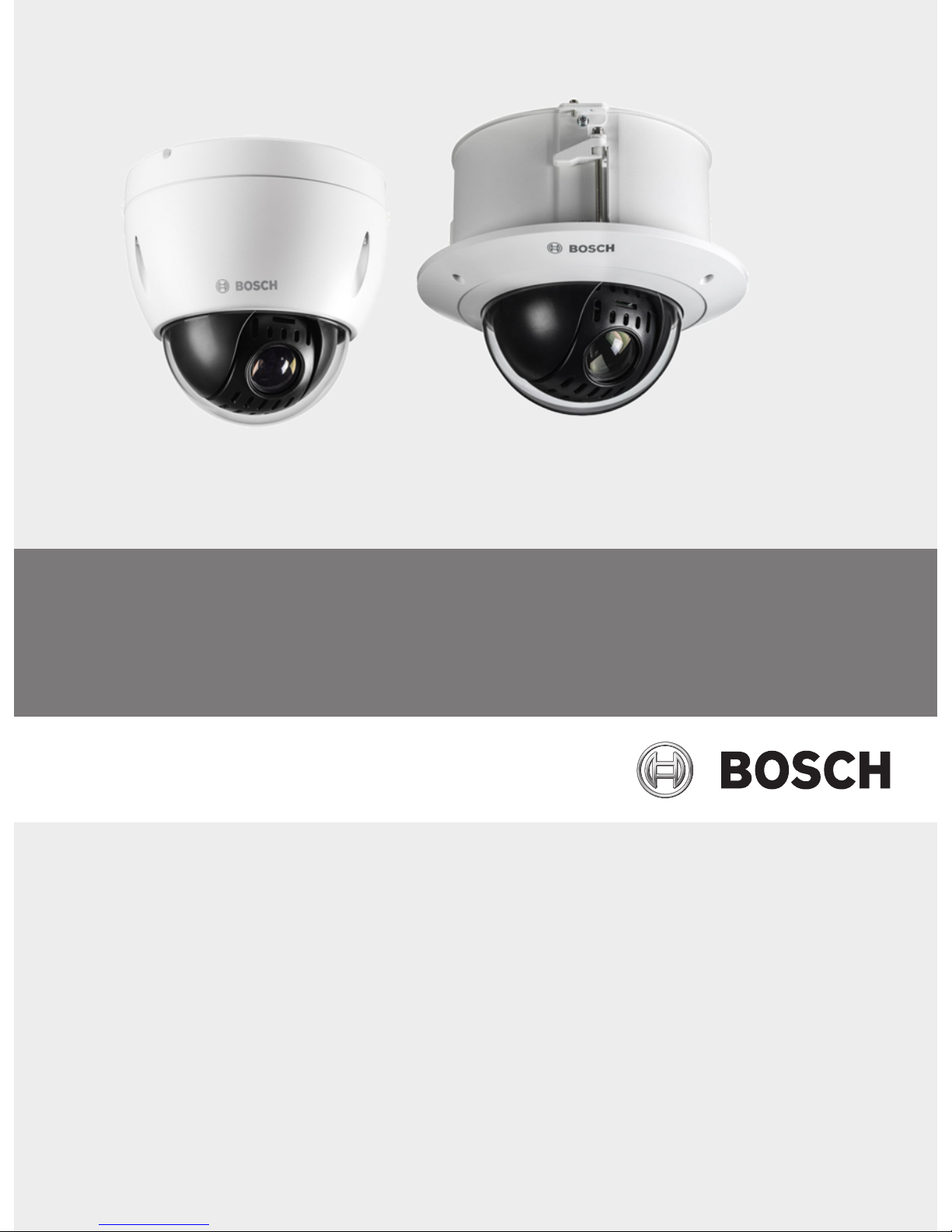
The AUTODOME IP 4000 HD is a compact, indoor PTZ dome camera with a high-resolution
720p25/30 (1MP) or 1080p25/30 (2MP) HD sensor and a powerful 12x optical zoom that
allows operators to monitor wide scenes without losing any details. The camera’s aesthetic
design and flexible mounting options allow unobtrusive surveillance of large halls, reception
areas, or waiting areas that would otherwise require multiple cameras for effective
surveillance.
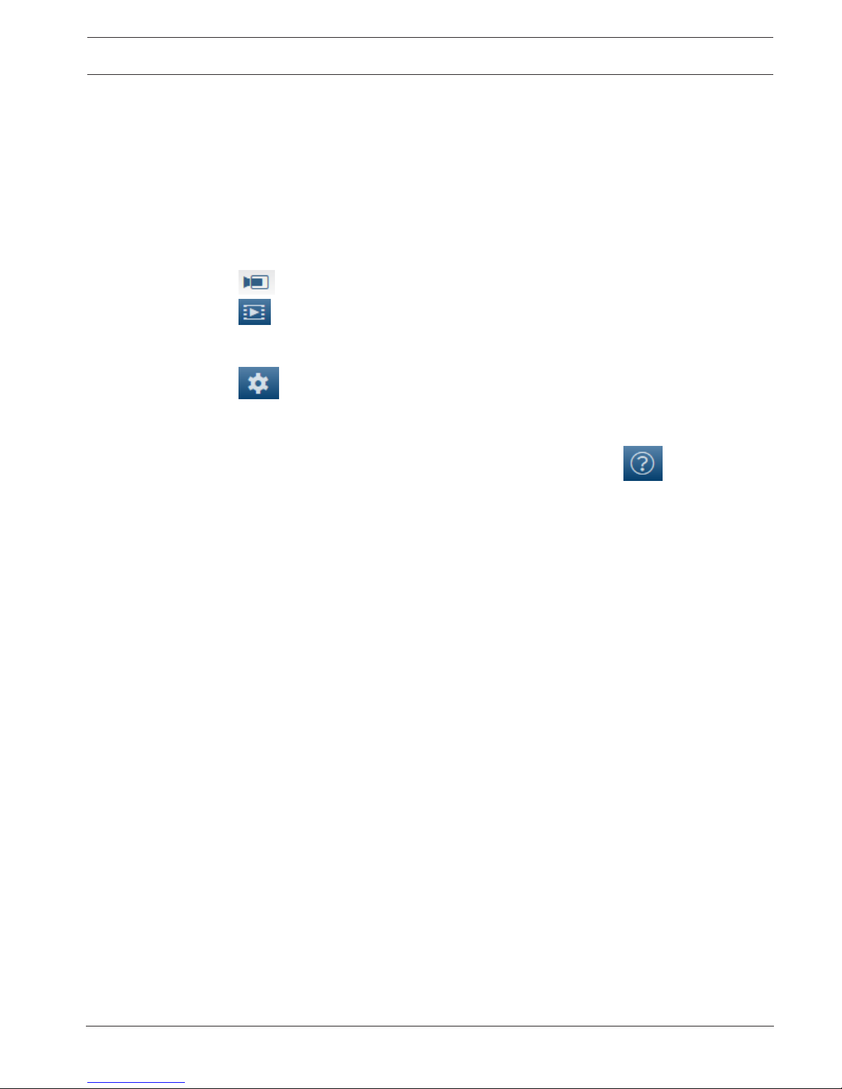
When a connection is established, the Live page is initially displayed. The application bar
displays the following items:
– Live,
– Playback,
This link is only visible if a storage medium has been configured for recording. (With VRM
recording this option is not active.)
– Configuration.
Getting help
To get context sensitive help for a particular page, click the help icon .
12 en | Mounting Accessories AUTODOME IP 4000 HD
2015.11 | 1.1 | Installation Manual Bosch Security Systems
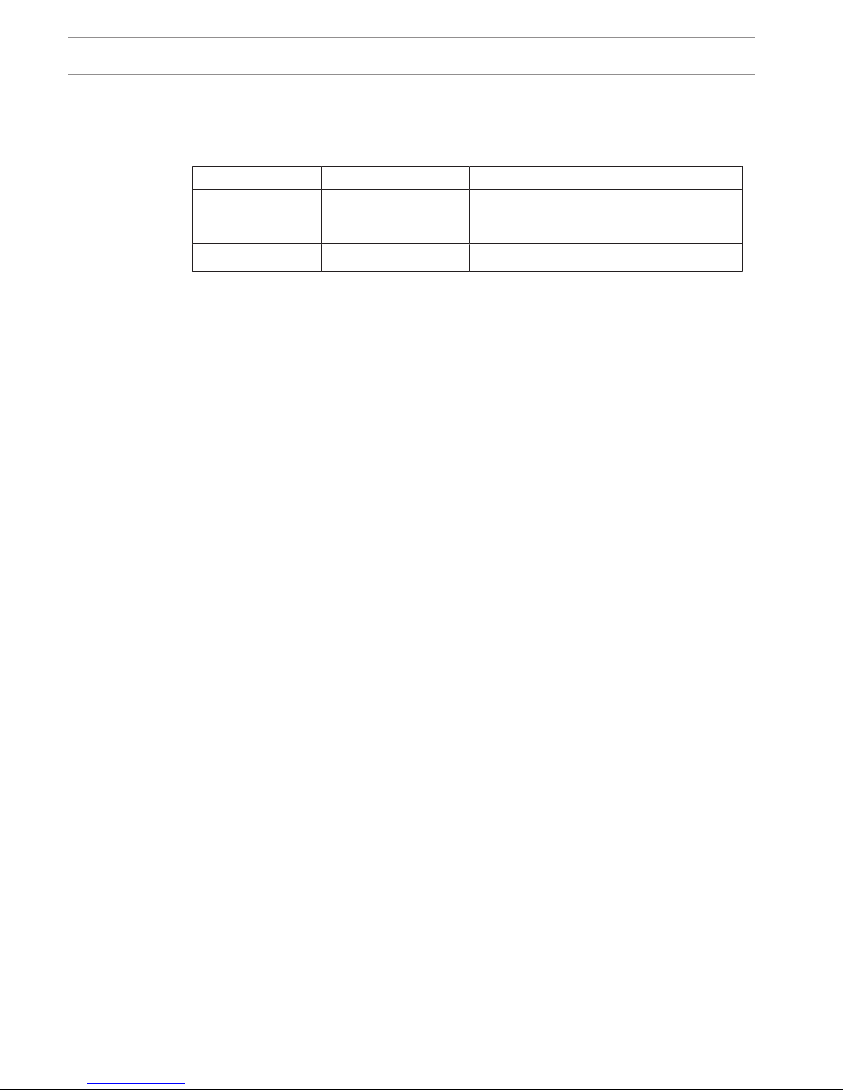
4 Mounting Accessories
The following mounting accessories are available (and are supplied with separate mounting
instructions) for AUTODOME IP 4000 HD cameras.
Model Number Description Application
NEZ-A4-WW Wall mount kit Indoor/outdoor vertical walls
NEZ-A4-PW Pipe mount kit Indoor/outdoor high ceilings
NEZ-A4-SMB Surface mount kit Indoor hard-ceiling

AUTODOME IP 4000 HD Installation Overview | en 13
Bosch Security Systems Installation Manual 2015.11 | 1.1 |
5 Installation Overview
!
Caution!
Installation must be made by qualified personnel and conform to ANSI/NFPA 70 (the National
Electrical Code® (NEC)), Canadian Electrical Code, Part I (also called CE Code or CSA C22.1),
and all applicable local codes. Bosch Security Systems, Inc. accepts no liability for any
damages or losses caused by incorrect or improper installation.
1. Select the mounting location.
Select a secure installation location and mounting position for the device. Ideally, this is a
location where the device cannot be interfered with either intentionally or accidentally.
4 Ensure that the selected mounting surface is capable of supporting the combined weight
of the camera and mounting hardware (sold separately) under all expected conditions of
load, vibration, and temperature.
5.1 Prepare Wiring
4 Prepare and install all wiring for 24 VAC, PoE+ (Cat5e/Cat6), alarms, and audio as
necessary. For 24 VAC, follow the recommendations for maximum cable distance and
wire gage.
Maximum cable distance in meters (feet) per minimum cable diameter
The following table identifies the recommended transmission distance (maximum) in meters
(feet), based on the specified wattage, per the minimum cable diameter (in mm²), when the
cable diameter is fixed and the maximum permitted power consumption for 24 VAC is 10%.
For example, for a device of 20 W and a minimum cable diameter of 1.0 mm², the
recommended transmission distance is 42 m (141 feet) from the transformer.
Models Watts 1.0 mm² 1.5 mm² 2.5 mm² 4.0 mm²
Indoor
(ceiling)
20 42 m (141 ft) 68 m (225 ft) 109 m (358 ft) 275 m (905 ft)
Outdoor 30 28 m (94 ft) 45 m (150 ft) 72 m (238 ft) 183 m (603 ft)
Wire Gage
Note: Metric wire sizes are standard DIN sizes, ISO6722, mm².
Wire diameter (mm²) AWG
1.0 18
1.5 16
2.5 14
4.0 12
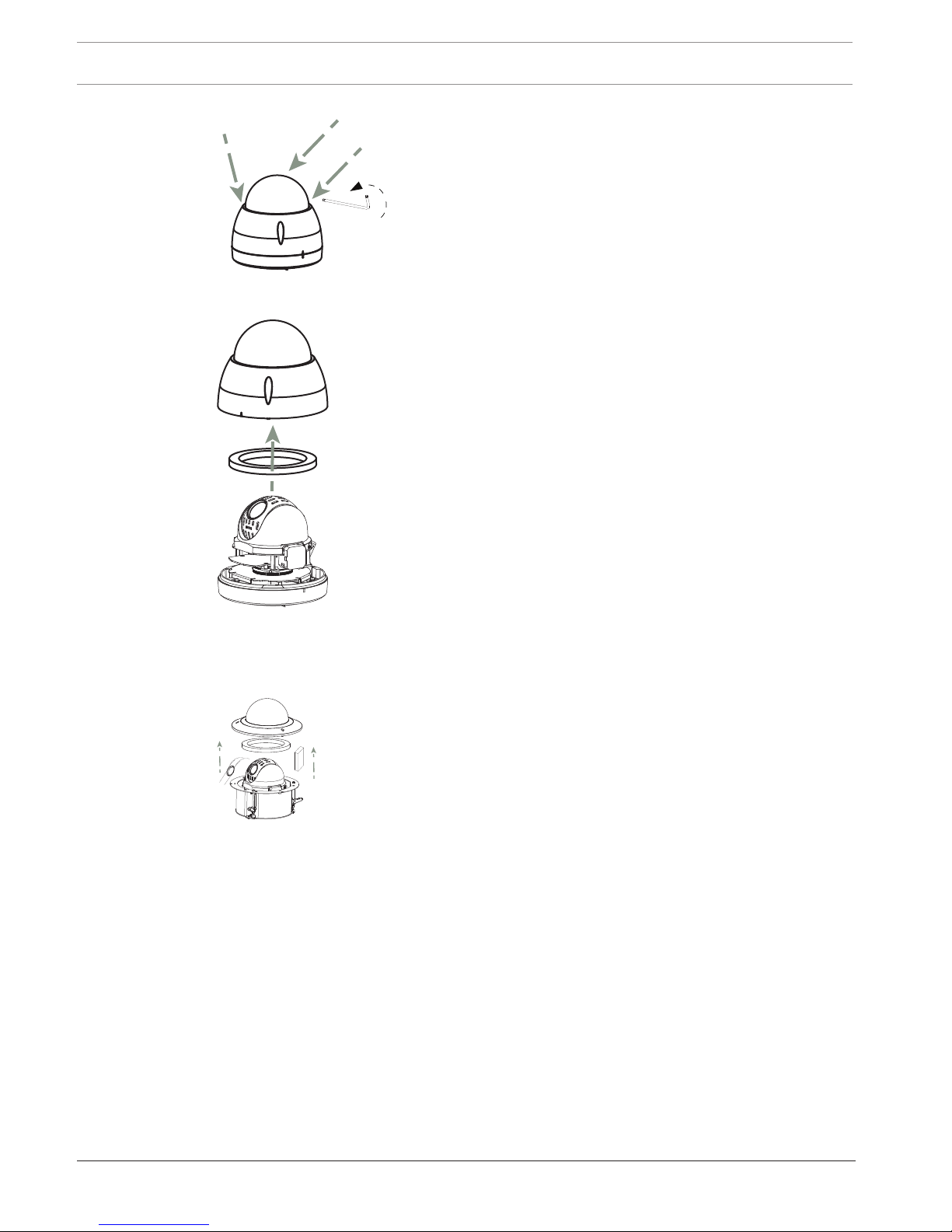
5.2 Prepare the Camera
1. Loosen the three (3) Hex screws in the trim ring / bubble enclosure with the T15 Torx
screwdriver.
14 en | Installation Overview AUTODOME IP 4000 HD
2015.11 | 1.1 | Installation Manual Bosch Security Systems
1
2
3
Figure5.1: Loosen enclosure screws (pendant models)
2. Remove the trim ring / bubble enclosure.
Figure5.2: Remove trim ring and bubble (pendant models)
Note: The next two steps are for the in-ceiling model only.
1. Remove the foam insert that protects the camera block.
2. Remove the tape holding the plastic lens protector; remove the lens protector.
1
2
3
Figure5.3: Remove trim ring/bubble, packing (in-ceiling model)
AUTODOME IP 4000 HD Installing a microSD card (optional) | en 15
Bosch Security Systems Installation Manual 2015.11 | 1.1 |
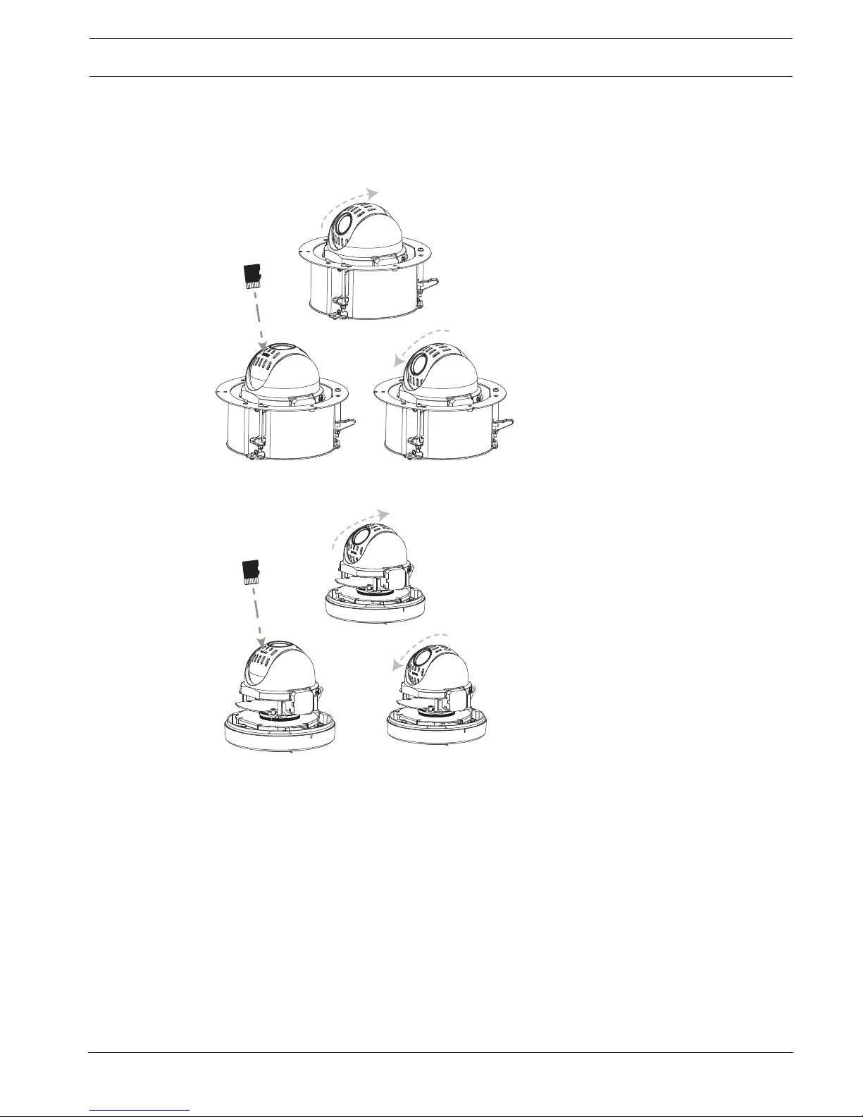
6 Installing a microSD card (optional)
1. Push the camera block until you see the card slot (item 1 in the following figure).
2. Insert the card into the slot (item 2 in the following figure).
3. Push the camera block into its original position (item 3 in the following figure).
microSD Card
1
2 3
Figure6.1: Insert SD card (in-ceiling model)
1
2 3
microSD Card
Figure6.2: Insert SD card (pendant models)
Note: The next two steps are for pendant models only.
1. Replace the trim ring / bubble enclosure.
2. Tighten the screws with the T15 Torx screwdriver.
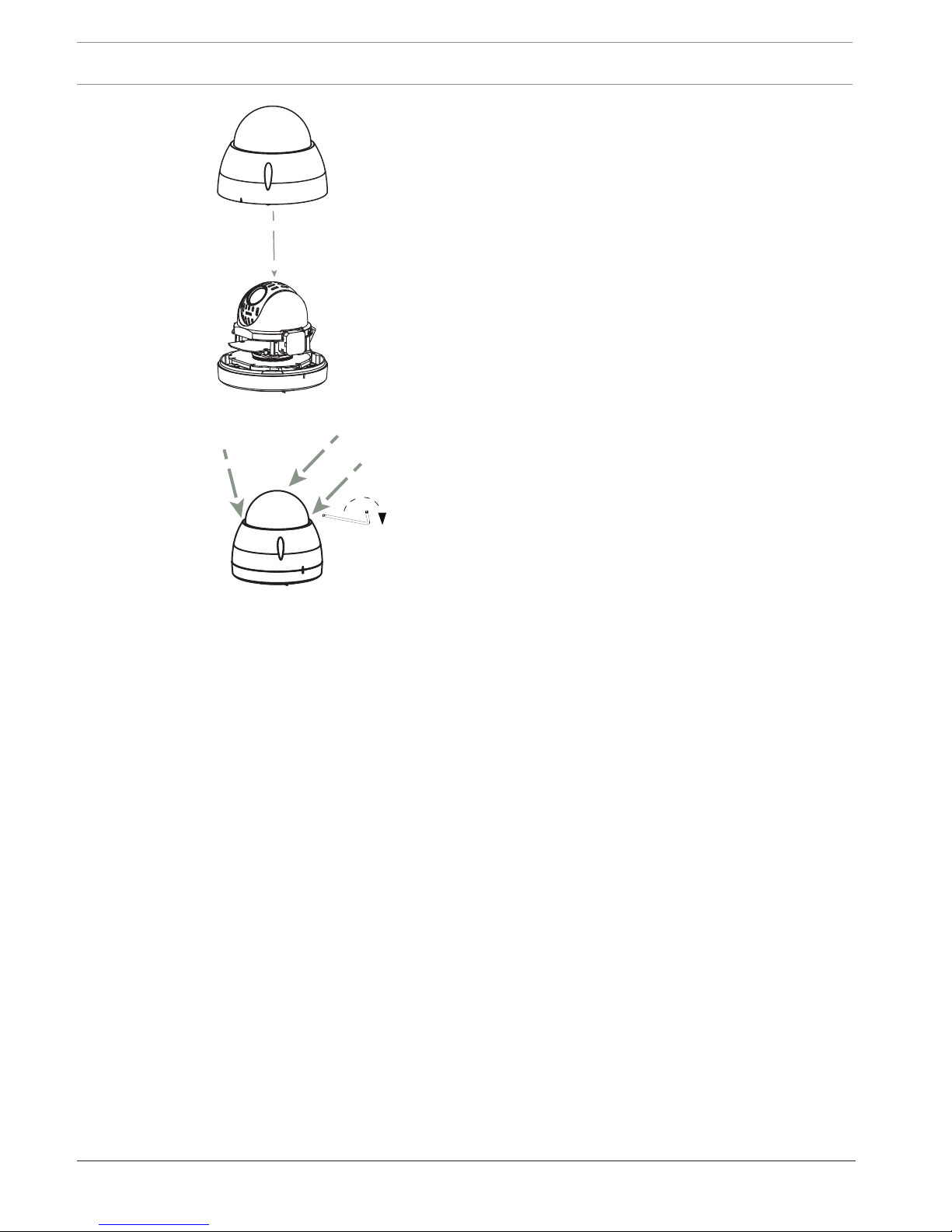
16 en | Installing a microSD card (optional) AUTODOME IP 4000 HD
2015.11 | 1.1 | Installation Manual Bosch Security Systems
Figure6.3: Replace trim ring/bubble (pendant models)
1
2
3
Figure6.4: Tighten screws (pendant models)
3. Proceed with installation.
AUTODOME IP 4000 HD Installing an In-Ceiling Camera in a Drywall Ceiling | en 17
Bosch Security Systems Installation Manual 2015.11 | 1.1 |
7 Installing an In-Ceiling Camera in a Drywall Ceiling
7.1 Tools Required
– Appropriate straight slot screwdriver
– Appropriate tool for cutting a hole in drywall or ceiling tile (if applicable)
7.2 Installation Requirements
– The ceiling thickness ranges from 10 - 40 mm.
– The ceiling can sustain at least eight (8) times the weight of the camera (1.81 kg (4 lb)): >
14.5 kg (32 lb).
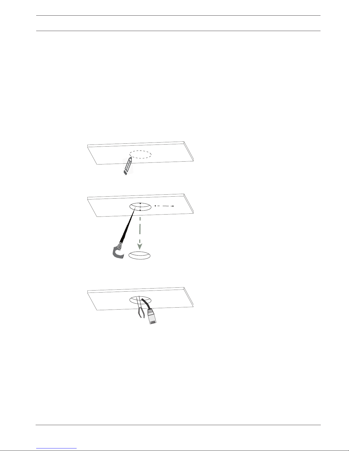
7.3 Preparing the Ceiling for Installation
1. Use the template to mark the hole in the ceiling for the camera.
> 15 kg
(33 lb)
Figure7.1: Mark hole with Template
2. Cut the hole in the ceiling with a drywall utility saw or jig saw.
160 mm
(6.3 in.)
Figure7.2: Cut hole in ceiling
3. Pull the cables (24 VAC, CAT 5/CAT6, alarm and/or audio as needed) through the hole in
the ceiling.
Figure7.3: Cables from ceiling
7.4 Securing the Camera to the Ceiling
1. Connect the cables from the ceiling to the cables on the camera. Refer to the chapter
Connection for more information.
18 en | Installing an In-Ceiling Camera in a Drywall Ceiling AUTODOME IP 4000 HD
2015.11 | 1.1 | Installation Manual Bosch Security Systems
24VAC
RJ45
24VAC
Figure7.4: Connect cables to camera
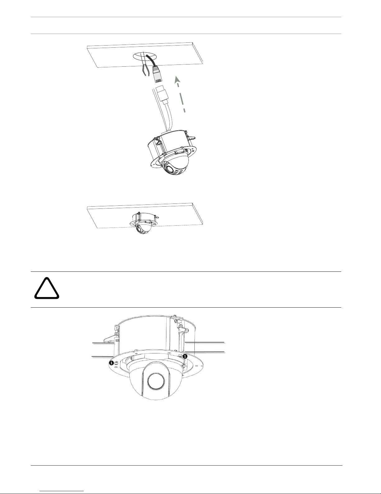
2. Insert the camera (without the trim ring / bubble enclosure) into the hole in the ceiling.
Ensure not to pinch the cables.
Figure7.5: Insert camera into hole
3. Turn each fastening screw (item 1 in the following figure) to secure the clamps in the
ceiling.
4. Tighten the clamps using the T10 Torx screwdriver to secure the housing to the ceiling.
!
Warning!
Over torquing the ceiling clamps can damage the clamp or ceiling. Only tighten the clamp
until it contacts the ceiling and you start to feel some resistance. If using a power
screwdriver, set the torque level to the lowest setting.
Figure7.6: Secure clamps to ceiling
5. Place the trim ring / bubble enclosure in position over the camera block, aligning the
three (3) screws (item 1 in the following figure). Tighten the screws firmly to secure the
trim ring / bubble enclosure to the in-ceiling bracket.
6. Remove the protective plastic sheet from the bubble. Installation is complete.
 Loading...