

Bosch MIC IP starlight 7000i, MIC-7502-Z30B, MIC-7502-Z30W, MIC-7502-Z30G User Manual
MIC IP starlight 7000i
MIC-7502-Z30B│MIC-7502-Z30W│MIC-7502-Z30G
en
User Manual


MIC IP starlight 7000i Table of contents | en 3
Bosch Security Systems User Manual 2017.11 | 1.2 |
Table of contents
1
Browser connection 5
1.1 Systems requirements 5
1.2 Establishing the connection 5
1.3 Password protection in camera 5
2
System overview 7
2.1 Live page 7
2.2 Configuration 7
2.3 Playback 7
3
Operation via the browser 8
3.1 Live page 8
3.1.1 Connection 8
3.1.2 PTZ 8
3.1.3 Pre-positions 8
3.1.4 AUX Control 9
3.1.5 Intelligent Tracking 9
3.1.6 Special Functions 9
3.1.7 Recording status 10
3.1.8 Saving snapshots 10
3.1.9 Recording live video 10
3.1.10 Full-screen display 10
3.1.11 Video Security App 10
3.1.12 Date and Time 10
3.1.13 Audio communication 10
3.1.14 Storage, CPU and network status 11
3.1.15 Status icons 11
3.2 Playback via browser 12
3.2.1 Selecting the recording stream 12
3.2.2 Searching for recorded video 12
3.2.3 Exporting recorded video 12
3.2.4 Controlling playback 12
4
General 14
4.1 Identification 14
4.2 User Management 14
4.3 Date/Time 15
4.4 Display Stamping 16
4.5 GB/T 28181 18
5
Web Interface 20
5.1 Appearance 20
5.2 LIVE Functions 21
6
Camera 23
6.1 Installer Menu 23
6.1.1 Positioning 23
6.2 Encoder Profile 26
6.3 Encoder Streams 29
6.4 Privacy Masks 31
6.5 Picture Settings 32
6.6 Lens Settings 35
6.7 PTZ Settings 36

4 en | Table of contents MIC IP starlight 7000i
2017.11 | 1.2 | User Manual Bosch Security Systems
6.8 Scene Mode Scheduler 38
6.9 Pre-positions and Tours 38
6.10 Pre-position mapping 39
6.11 Sectors 39
6.12 Miscellaneous 39
6.13 Illumination/Wiper 39
6.14 Audio 41
6.15 Pixel Counter 41
7
Alarm 42
7.1 Alarm Connections 42
7.2 Video Content Analysis (VCA) 44
7.3 Virtual Masks 45
7.4 Audio Alarm 46
7.5 Alarm E-Mail 46
7.6 Alarm Task Editor 47
7.7 Alarm Rules 48
8
Interfaces 49
8.1 COM1 49
9
Network 50
9.1 Network Services 50
9.2 DynDNS 50
9.3 Advanced 51
9.4 Network Management 52
9.5 Multicast 52
9.6 Image Posting 53
9.7 Accounts 54
9.8 IPv4 Filter 55
9.9 Encryption 55
10
Service 56
10.1 Maintenance 56
10.2 Licenses 56
10.3 Certificates 56
10.4 Logging 57
10.5 Diagnostics 57
10.6 System Overview 57
11
Using your MIC Camera 58
11.1 Recommended Use of Your MIC Camera 58
11.2 Using Intelligent Tracking 59
11.3 Uploading a User Logo 62
11.4 Azimuth, Elevation, and Compass Directions 63
11.5 Using the Wiper/Washer (Bosch Protocol) 64
11.6 Using the Wiper/Washer (Pelco Protocol) 65
11.7 Configuring Settings for IR Illumination 66
12
Troubleshooting 67
13
Status Codes 71
14
AUX Commands 76

MIC IP starlight 7000i Browser connection | en 5
Bosch Security Systems User Manual 2017.11 | 1.2 |
1 Browser connection
A computer with Microsoft Internet Explorer is used to receive live images, control the unit,
and replay stored sequences. The unit is configured over the network using the browser.
1.1 Systems requirements
Our recommendations are:
– Computer with Intel Skylake processor or better
– Intel HD530 graphic card with performance that matches or is better than the resolution
of the camera
– Windows7 or later operating system
– Network access
– Internet Explorer version 11 or later
– or –
Application software, for example, VideoSecurityClient, BoschVideoClient or Bosch
Video Management System.
Note:
To see live images in your browser it might be necessary to download and install the MPEGActiveX from the Bosch download store.
1.2 Establishing the connection
The unit must have a valid IP address to operate on your network and a compatible subnet
mask.
By default, DHCP is pre-set at the factory to On plus Link-Local so a DHCP server assigns an
IP address or, if no DHCP server is available, a link-local address (auto-IP) is assigned within
the range 169.254.1.0 to 169.254.254.255.
You can use IP Helper or Configuration Manager to find the IP address. Download the software
from http://downloadstore.boschsecurity.com.
1. Start the Web browser.
2. Enter the IP address of the unit as the URL.
3. During initial installation, confirm any security questions that appear.
If a RADIUS server is used for network access control (802.1x authentication), you must
configure the device before the device can communicate with the network.
To configure the device, connect it directly to a computer using a network cable and then set
the service-level password.
Note:
If you cannot connect, the unit may have reached its maximum number of connections.
Depending on the device and network configuration, each unit can have up to 50 web browser
connections, or up to 100 connections via BoschVideoClient or Bosch Video Management
System.
1.3 Password protection in camera
The device is password-protected. The first time that any user accesses the device, the device
will prompt the user to set a password at the service level.
The camera requires a strong password. Follow the prompts in the dialog box, which specifies
what is required. The system measures the strength of the password that you enter.

6 en | Browser connection MIC IP starlight 7000i
2017.11 | 1.2 | User Manual Bosch Security Systems
When you use Configuration Manager to access your device for the first time, you must set the
initial password of the device in Configuration Manager. The Users section (General > Unit
Access > Users) displays the message, "Before you can use this device you have to secure it
with an initial password."
Note: After you set the initial password, a "lock" icon appears next to the device name in the
Devices list in Configuration Manager.
You can also launch the device webpage directly. In the device webpage, an initial password
page appears, displaying input fields and a password strength gauge.
Enter the user name (“service”) and a password in the appropriate fields. Refer to the section
User Management for more information.
After a service-level password is set for the device, the device displays a dialog box that
prompts users to enter the user name (“service”) and the service-level password every time
that they access the device.
1. Fill in the fields User name and Password.
2. Click OK. If the password is correct, the desired page appears.
MIC IP starlight 7000i System overview | en 7
Bosch Security Systems User Manual 2017.11 | 1.2 |
2 System overview
When a connection is established, the Live page is initially displayed.
The application bar displays the following icons:
Live To view the live video stream, click this icon.
Playback To play back recorded sequences, click this icon.
This link is only visible if a storage medium has been
configured for recording. (With VRM recording this
option is not active.)
Configuration To configure the unit, click this icon.
Links To navigate to the Bosch download store, click this
icon.
To get context sensitive help for a particular page, click
this icon.
Note: None of the pages are accessible until after you set a service-level password.
2.1 Live page
The Live page is used to display the live video stream and control the unit.
2.2 Configuration
The Configuration page is used to configure the unit and the application interface.
Making Changes
Each configuration screen shows the current settings. You can change the settings by entering
new values or by selecting a predefined value from a list field.
Not every page has a Set button. Changes to pages without a Set button are set immediately.
If a page does show a Set button, you must click the Set button for a change to take effect.
Notice!
Save each change with the associated Set button.
Clicking the Set button saves the settings only in the current field. Changes in any other fields
are ignored.
Some changes only take effect after the unit is rebooted. In this case, the Set button changes
to Set and Reboot.
1. Make the desired changes.
2. Click the Set and Reboot button. The camera reboots and the changed settings are
activated.
All settings are backed up in camera memory so they are not lost even if the power fails. The
exception is the time settings, which are lost after 1 hour without power if no central time
server is selected.
2.3 Playback
The Playback page is used for playing back recorded sequences.
8 en | Operation via the browser MIC IP starlight 7000i
2017.11 | 1.2 | User Manual Bosch Security Systems
3 Operation via the browser
3.1 Live page
3.1.1 Connection
Stream 1
Select this option to display stream 1 of the camera.
Stream 2
Select this option to display stream 2 of the camera.
M-JPEG
Select this option to display the M-JPEG stream of the camera.
3.1.2 PTZ
Pan and tilt controls
– To tilt the camera up: Click and hold the up arrow.
– To tilt the camera down: Click and hold the down arrow.
– To pan the camera left: Click and hold the left arrow.
– To pan the camera right: Click and hold the right arrow.
– To pan and tilt the camera at the same time (variable pan/tilt): Click and drag the center
area (that resembles a point stick or a trackball on a computer keyboard) around the PTZ
control in the direction that you want to move the camera.
Notice!
If the camera will not pan in either direction, or pans in one direction only, refer to the “Error
Codes” section of the manual.
Zoom
Click the + button to zoom in.
Click the - button to zoom out.
Iris
Click (Iris close) to close the iris.
Click (Iris open) to open the iris.
Focus
Click to focus near.
Click to focus far.
3.1.3 Pre-positions
The camera displays Pre-position 1 through Pre-position 6. Select the appropriate preposition to view the video image for that pre-position/scene. In the lower left of the video
image, the OSD displays the Camera number (title), the Pre-position number, and the Preposition number stored.
Below the list of pre-positions/scenes is a drop-down list showing the stored pre-positions/
scenes.
Select the appropriate pre-position (1 through 6). Click to store the pre-position.
MIC IP starlight 7000i Operation via the browser | en 9
Bosch Security Systems User Manual 2017.11 | 1.2 |
Note: If the pre-position is already stored, a dialog box displays the message, “Overwrite
current pre-position?” Click OK to overwrite, or click Cancel to cancel the operation.
Click to display the selected pre-position in the video image.
3.1.4 AUX Control
With the tab AUX Control you can enter pre-programmed keyboard control commands. These
commands are composed of a command number plus the appropriate function key (Show pre-
position, Set pre-position, AUX on, or AUX off). A valid combination either issues a command
to the device or displays an on-screen menu.
(Refer to the “Keyboard Commands“ section of the manual for a list of all AUX commands for
your camera.)
Show pre-position
Click this button to display a pre-position.
Set pre-position
Click this button to set a pre-position.
AUX on
Click this button to activate an AUX command.
AUX off
Click this button to deactivate an AUX command.
3.1.5 Intelligent Tracking
Options for tracking objects within the region of interest appear in the panel.
When Intelligent Tracking is active, the tracking icon appears on the image along with
the lines that track moving objects.
Select Off, Auto or Click. If Click is selected, click on an object to track it.
3.1.6 Special Functions
Scan 360°
Click this button to start a continuous 360° pan. To stop the continuous pan, click a
directional control in the View Control tab.
Autopan
Click this button to pan the camera between user-defined limits.
Tour A / Tour B
Click one of these buttons to start the continuous playback of a recorded (guard) tour. A
recorded tour saves all manual camera movements made during the recording, including its
rate of pan, tilt and zoom speeds, and other lens setting changes.
To stop a tour, click a directional control in the View Control tab.
Focus
Click this button to activate the Auto Focus One Push mode on the camera.
The OSD displays the message, “Auto Focus: ONE PUSH.”
White light
Click this button to turn on the White light of the illuminator accessory (if available on your
camera).
Click this button again to turn off the White light.
10 en | Operation via the browser MIC IP starlight 7000i
2017.11 | 1.2 | User Manual Bosch Security Systems
Custom tour
Click this button to view (in continuous playback) a custom tour that was previously
configured.
3.1.7 Recording status
The hard drive icon below the live camera image changes during an automatic recording.
The icon lights up and displays a moving graphic to indicate a running recording. If no
recording is taking place, a static icon is displayed.
3.1.8 Saving snapshots
Individual images from the displayed live video stream can be saved locally in JPEG format on
the computer's hard drive. The storage location depends on the configuration of the camera.
– Click the photo camera icon to save a single image.
3.1.9 Recording live video
Video sequences from the displayed live video stream can be saved locally on the computer's
hard drive. The sequences are recorded at the resolution specified in the encoder
configuration. The storage location depends on the configuration of the camera.
1. Click the recording icon to record video sequences.
– Saving begins immediately. The red dot on the icon indicates that a recording is in
progress.
2. Click the recording icon again to stop recording.
3.1.10 Full-screen display
Click the full-screen icon to view the selected stream in full-screen mode; press Esc
on the keyboard to return to the normal viewing window.
3.1.11 Video Security App
Start Video Security app
To start the Video Security app, click .
3.1.12 Date and Time
Date/Time (unlabeled)
The unlabeled date and time ticker appears above the row of icons (including
) that is below the lower-left corner of the live video image.
3.1.13 Audio communication
Audio can be sent and received via the Live page if the unit and the computer support audio.
1. Press and hold the F12 key on the keyboard to send an audio signal to the unit.
2. Release the key to stop sending audio.
MIC IP starlight 7000i Operation via the browser | en 11
Bosch Security Systems User Manual 2017.11 | 1.2 |
All connected users receive audio signals sent from the unit but only the user who first
pressed the F12 key can send audio signals; others must wait for the first user to release the
key.
3.1.14 Storage, CPU and network status
When accessing the unit with a browser, the local storage, processor and network status
icons are shown in the upper right of the window.
When a local storage card is available, the memory card icon changes color (green, orange or
red) to indicate the local storage activity. If you hover over this icon with the mouse the
storage activity is shown as a percentage.
If you hover over the middle icon, the CPU load is shown.
If you hover over the right-hand icon, the network load is shown.
This information can help with problem solving or when fine tuning the unit. For example:
– if the storage activity is too high, change the recording profile,
– if the CPU load is too big, change the VCA settings,
– if the network load is too big, change the encoder profile to reduce bitrate.
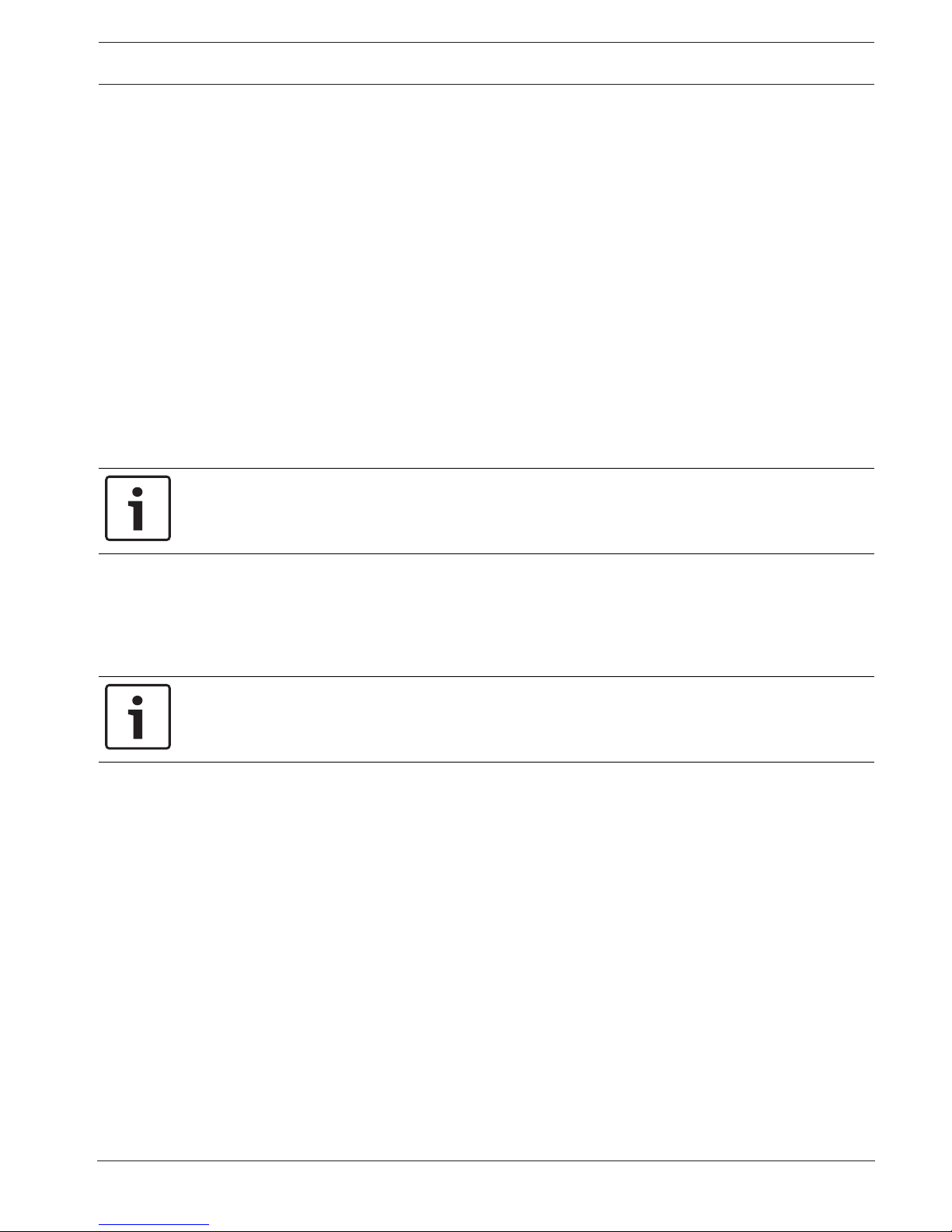
3.1.15 Status icons
Various overlays in the video image provide important status information. The overlays provide
the following information:
Decoding error
The frame might show artifacts due to decoding errors.
Alarm flag
Indicates that an alarm has occurred.
Communication error
A communication error, such as a connection failure to the storage medium, a protocol
violation or a timeout, is indicated by this icon.
Gap
Indicates a gap in the recorded video.
Watermark valid
The watermark set on the media item is valid. The color of the check mark changes according
to the video authentication method that has been selected.
Watermark invalid
Indicates that the watermark is not valid.
Motion alarm
Indicates that a motion alarm has occurred.
Storage discovery
Indicates that recorded video is being retrieved.

12 en | Operation via the browser MIC IP starlight 7000i
2017.11 | 1.2 | User Manual Bosch Security Systems
3.2 Playback via browser
Click Playback in the application bar to view, search or export recordings. This link is
only visible if a direct iSCSI or memory card has been configured for recording. (With VRM
recording this option is not active.)
The panel on the left has four groups:
– Connection
– Search
– Export
– Track list
3.2.1 Selecting the recording stream
On the left side of the browser, expand the Connection group if necessary.
To view a recording stream:
1. Click the Recording drop-down arrow to see the options.
2. Select recording stream 1 or 2.
3.2.2 Searching for recorded video
On the left side of the browser, expand the Search group if necessary.
1. To limit the search to a particular time range, enter the date and times for the start and
stop points.
2. Select an option from the drop-down box to define a search parameter.
3. Click Start Search.
4. The results are shown.
5. Click a result to play it back.
6. Click Back to define a new search.
3.2.3 Exporting recorded video
On the left side of the browser, expand the Export group if necessary.
1. Select a track in the track list or in the search results (or click on the timeline below the
video window and drag the buttons to mark the sequence you want to export).
2. The start and stop date and time are filled-in for the selected track. If required, change
the times.
3. In the Time lapse drop-down box, select the original or a condensed speed.
4. In the Location drop-down box, select a target.
5. Click Export to save the video track.
Note:
The target server address is set on the Network / Accounts page.
3.2.4 Controlling playback
The time bar below the video image allows quick orientation. The time interval associated with
the sequence is displayed in the bar in gray. Arrows indicate the position of the image
currently being played back within the sequence.
The time bar offers various options for navigation in and between sequences.
– If required, click in the bar at the point in time at which the playback should begin.
– Change the time interval displayed by clicking the plus or minus icons or use the mouse
scroll wheel. The display can span a range from six months to one minute.
– Click the alarm jump buttons to go from one alarm event to the next or to the previous
one. Red bars indicate the points in time where alarms were triggered.

MIC IP starlight 7000i Operation via the browser | en 13
Bosch Security Systems User Manual 2017.11 | 1.2 |
Controls
Control playback by means of the buttons below the video image.
The buttons have the following functions:
– Start/Pause playback
– Select the playback (forward or backward) speed using the speed regulator
– Step forward or backward frame-by-frame when paused (small arrows)

14 en | General MIC IP starlight 7000i
2017.11 | 1.2 | User Manual Bosch Security Systems
4 General
4.1 Identification
Device name
Enter a unique, unambiguous name for the device (for example, the installation location of the
device). This name should be easy to identify in a list of devices in your system. The device
name is used for the remote identification of a unit, such as in the event of an alarm.
Do not use any special characters, for example &, in the name. Special characters are not
supported by the system's internal management.
Device ID
Enter a unique identifier for the device. This ID is additional identification for the device.
Initiator extension
Add text to an initiator name to make identification easier in large iSCSI systems. This text is
added to the initiator name, separated from it by a full stop. (You can see the initiator name in
the System Overview page.)
4.2 User Management
The section Allowed authentication modes provides information about the authentication
modes set in the camera. A checkmark appears in the checkbox to the left of the mode if the
mode is set. If the mode is not set, the phrase, “No certificate installed” appears to the right
of the mode name.
Password
This field indicates if a password is set for the camera.
Certificate
A check mark in this check box indicates that at least one certificate is loaded onto the
camera. If no certificates are loaded, then “No certificate installed” appears to the right of the
text.
The Escrypt certificate is a root certificate for Bosch Security Systems that proves that the
device meets the following criteria:
– It originates from a Bosch factory that is a secure environment.
– It has not been tampered with.
Escrypt is a Bosch company and Certificate Authority (CA).
Active directory server (ADFS)
A check mark in this check box indicates that the camera uses an active directory server. If the
camera does not use ADFS, then “No certificate installed” appears to the right of the text.
Password management
A password prevents unauthorized access to the device. You can use different authorization
levels to limit access.
Proper password protection is only guaranteed when all higher authorization levels are also
protected with a password. Therefore, you must always start from the highest authorization
level when assigning passwords.
You can define and change a password for each authorization level if you are logged into the
“service” user account.
The device has three authorization levels: service, user, and live.
– service is the highest authorization level. Entering the correct password gives access to
all the functions and allows all configuration settings to be changed.
MIC IP starlight 7000i General | en 15
Bosch Security Systems User Manual 2017.11 | 1.2 |
– user is the middle authorization level. At this level you can operate the device, play back
recordings, and also control camera, for example, but you cannot change the
configuration.
– live is the lowest authorization level. At this level you can only view the live video image
and switch between the different live image displays.
To edit a password
To edit a password, click the pencil icon to the right of the column Type for the appropriate
User name.
To create a new user
To create a new user, click Add.
In the box User, fill in the fields. For Group, select the appropriate authorization level. For
Type, select either Password (for a new password) or Certificate (for a certificate that the
new user is authorized to use).
Note: Use a maximum of 19 characters. Do no use special characters.
Confirm password
In each case, enter the new password a second time to eliminate typing mistakes.
Notice!
A new password is only saved when you click the Set button. You should therefore click the
Set button immediately after entering and confirming a password.
4.3 Date/Time
Date format
Select your required date format.
Device date/Device time
Notice!
Ensure that recording is stopped before synching to the PC.
If there are multiple devices operating in your system or network, it is important to
synchronize their internal clocks. For example, it is only possible to identify and correctly
evaluate simultaneous recordings when all units are operating on the same time.
1. Enter the current date. Since the unit time is controlled by the internal clock, there is no
need to enter the day of the week – it is added automatically.
2. Enter the current time or click the Sync to PC button to copy your computer's system
time to the camera.
Note: It is important that the date/time is correct for recording. An incorrect date/time setting
could prevent correct recording.
Device time zone
Select the time zone in which your system is located.
Daylight saving time
The internal clock can switch automatically between normal and daylight saving time (DST).
The unit already contains the data for DST switch-overs for many years in advance. If the date,
time and zone have been set up correctly, a DST table is automatically created.

16 en | General MIC IP starlight 7000i
2017.11 | 1.2 | User Manual Bosch Security Systems
If you decide to create alternative daylight saving time dates by editing the table, note that
values occur in linked pairs (DST start and end dates).
First, check the time zone setting. If it is not correct, select the appropriate time zone and
click Set.
1. Click Details to edit the DST table.
2. Select the region or the city which is closest to the system's location from the list box
below the table.
3. Click Generate to fill the table with the preset values from the unit.
4. Click one of the entries in the table to make changes. The entry is highlighted.
5. Click Delete to remove the entry from the table.
6. Choose other values from the list boxes under the table, to change the selected entry.
Changes are immediate.
7. If there are empty lines at the bottom of the table, for example after deletions, add new
data by marking the row and selecting values from the list boxes.
8. When finished, click OK to save and activate the table.
Time server IP address
The camera can receive the time signal from a time server using various time server protocols,
and then use it to set the internal clock. The unit polls the time signal automatically once every
minute.
Enter the IP address of a time server here.
Time server type
Select the protocol that is supported by the selected time server. Preferably, you should
select the SNTP server as the protocol. This supports a high level of accuracy and is required
for special applications and subsequent function extensions.
Select Time server for a time server that works with the protocol RFC868.
4.4 Display Stamping
Various overlays or “stamps” in the video image provide important supplementary information.
These overlays can be enabled individually and are arranged on the image in a clear manner.
Camera name stamping
This field sets the position of the camera name overlay. It can be displayed at the Top, at the
Bottom or at a position of your choice that you can then specify using the Custom option. Or
it can be set to Off for no overlay information.
1. Select the desired option from the list.
2. If you select the Custom option, additional fields are displayed where you can specify the
exact position (Position (XY)).
3. In the Position (XY) fields, enter the values for the desired position.
Logo
To place a logo on the image, select and upload an uncompressed .bmp file with a maximum
size of 128x128 pixels and 256 colors to the camera. Its position on the image can then be
selected.
Logo position
Select the position for the logo on the OSD: To the left of the name, To the right of the
name, or Logo only.
Select Off (the default value) to disable logo positioning.

MIC IP starlight 7000i General | en 17
Bosch Security Systems User Manual 2017.11 | 1.2 |
Time stamping
This field sets the position of the time overlay. It can be displayed at the Top, at the Bottom or
at a position of your choice that you can then specify using the Custom option. Or it can be
set to Off for no overlay information.
1. Select the desired option from the list.
2. If you select the Custom option, additional fields are displayed where you can specify the
exact position (Position (XY)).
3. In the Position (XY) fields, enter the values for the desired position.
Display milliseconds
If necessary, you can also display milliseconds. This information can be useful for recorded
video images; however, it does increase the processor's computing time. Select Off if you do
not need to display milliseconds.
Live video indicator
Select On to display the Live video indicator, an icon that pulses on the OSD to show that the
video stream is live.
Select Off to hide the Live video indicator.
Alarm mode stamping
Select On to display a text message overlay in the image in the event of an alarm. It can be
displayed at a position of your choice that you can then specify using the Custom option. Or it
can be set to Off for no overlay information.
1. Select the desired option from the list.
2. If you select the Custom option, additional fields are displayed where you can specify the
exact position (Position (XY)).
3. In the Position (XY) fields, enter the values for the desired position.
Alarm message
Enter the message to be displayed in the image in the event of an alarm. The maximum text
length is 31 characters.
Title OSD
OSD titles can be displayed at a position of your choice.
Select On to display sector or pre-position title overlays continuously in the image.
Select Momentary to display sector or pre-position title overlays for a few seconds.
1. Select the desired option from the list.
2. Specify the exact position (Position (XY)).
3. In the Position (XY) fields, enter the values for the desired position.
Select Off to deactivate the display of overlay information.
Camera OSD
Select On to momentarily display camera response information, such as Digital Zoom, Iris
open/close, and Focus near/far overlays in the image. Select Off to display no information.
1. Select the desired option from the list.
2. Specify the exact position (Position (XY)).
3. In the Position (XY) fields, enter the values for the desired position.
Title region
Select On to set or to edit the position of the title region on the OSD.
The fields Position (XY) and (0...255) appear.
1. In the field Position (XY), specify the exact position. (The default is 10.)
2. In the field (0...255), enter the position range. (The default is 176).
Select Off to hide the region from view.

18 en | General MIC IP starlight 7000i
2017.11 | 1.2 | User Manual Bosch Security Systems
Telemetry region
Select On to set or to edit the position of the telemetry information (azimuth and elevation
(pan/tilt position)) and the zoom factor on the OSD. Refer to the section ”PTZ Settings, page
36“ to set the pan and tilt limits.
The fields Position (XY) and (0...255) appear.
1. In the field Position (XY), specify the exact position. (The default is 10.)
2. In the field (0...255), enter the position range. (The default is 176).
Select Off to hide the region from view.
Feedback region
Select On to set or to edit the position of system feedback messages (including message for
camera settings such as focus, iris, and zoom level) on the OSD. Refer to the section “Lens
Settings” to configure these settings.
The fields Position (XY) and (0...255) appear.
1. In the field Position (XY), specify the exact position. (The default is 10.)
2. In the field (0...255), enter the position range. (The default is 176).
Select Off to hide the region from view.
Transparent background
Check this box to make transparent the stamp background on the image.
Stamping size
Select the desired font size of the overlays on the OSD: Normal or Big.
Video authentication
Select from the Video authentication drop-down box a method for verifying the integrity of
the video.
If you select Watermarking, all images are marked with an icon. The icon indicates if the
sequence (live or saved) has been manipulated.
If you want to add a digital signature to the transmitted video images to ensure their integrity,
select one of the cryptographic algorithms for this signature.
Signature interval [s]
For certain Video authentication modes, enter the interval (in seconds) between insertions of
the digital signature.
4.5 GB/T 28181
This page allows you to set the parameters for conformance to the GB/T28181 national
standard “Security and protection video monitoring network system for information transport,
switch and control”. This standard is specifically for China.
Enable
Select this checkbox to enable the system to use the other parameters on this page in
accordance with the GB/T 28181 national standard.
H.264 elementary stream
Select this checkbox to select or to enable the H.264 elementary stream.
Registration timeout
Enter a value (in milliseconds) for the registration timeout. The default is 3600.
Heartbeat timeout
Enter the value (in seconds) for the heartbeat timeout. The default is 15.
Server ID
Enter the ID of the server.

MIC IP starlight 7000i General | en 19
Bosch Security Systems User Manual 2017.11 | 1.2 |
Server IP address
Enter the server IP address.
Device ID
Enter the ID of the device.
Device port
Enter the number of the device port. The default is 5060.
Password
Enter the appropriate password.
Alarm device ID
Enter the ID of the alarm device.
20 en | Web Interface MIC IP starlight 7000i
2017.11 | 1.2 | User Manual Bosch Security Systems
5 Web Interface
5.1 Appearance
You can adapt the appearance of the web interface and change the website language to meet
your requirements.
GIF or JPEG images can be used to replace the company and device logos. The image can be
stored on a web server (for example, http://www.myhostname.com/images/logo.gif).
Ensure that a connection to the web server is always available to display the image. The image
files are not stored on the unit.
To restore the original graphics, delete the entries in the Company logo and Device logo
fields.
Website language
Select the language for the user interface.
The default language is English. After selecting a different language, click the Set button. The
page refreshes automatically. The GUI now displays field names and options as well as OSD
messages in the selected language.
Company logo
To replace the company's logo in the top-right part of the window, enter the path to a suitable
image in this field. The image file must be stored on a web server.
Device logo
To replace the device name in the top-left part of the window, enter the path to a suitable
image in this field. The image file must be stored on a web server.
Notice!
If you want to use the original image again, delete the entries in the fields Company logo and
Device logo.
Show VCA metadata
When video content analysis (VCA) is activated, additional information is displayed in the live
video stream. With the MOTION+ analysis type, for example, the sensor fields in which motion
is recorded are marked with yellow rectangles.
Using EssentialVideoAnalytics or IntelligentVideoAnalytics, the outlines of detected objects
are displayed in following colors:
– Red: Objects that generate an alarm event under the current settings appear on the
camera image inside a red outline.
– Orange: An object that has triggered one alarm event but does not generate another
appears inside an orange outline (example: object has crossed a line). During forensic
search, an object that triggers an alarm event has an orange outline from the beginning.
– Yellow: Objects that are detected as moving but do not generate an alarm event under
the current settings appear inside a yellow outline.
The following table identifies the metadata that appear.
Image being viewed Imager that Detected Object Resulting outlines
Visible Visible imager Solid box
Thermal imager Dotted box
Thermal Visible imager Dotted box
Thermal imager Solid box

MIC IP starlight 7000i Web Interface | en 21
Bosch Security Systems User Manual 2017.11 | 1.2 |
Show VCA trajectories
The trajectories (motion lines of objects) from the video content analysis are displayed in the
live video image if a corresponding analysis type is activated. The trajectory is shown as a
green line following the object base point.
The following table identifies the trajectory lines that appear.
Image being viewed Imager that Detected Object Resulting trajectory lines
Visible Visible imager Solid green line
Thermal imager Dotted green line
Thermal Visible imager Dotted green line
Thermal imager Solid green line
Note: For details about how VCA objects appear on the Live page, refer to the section
Understanding the Fusion Feature.
Show overlay icons
Select this check box to show overlay icons on the live video image.
Show VCA items
Shows alarm fields, lines and routes configured for the video analytics in the following colors:
– Green: Fields, lines and routes used in a task are displayed in green. They can be edited
but not deleted.
– Red: Fields, lines and routes currently in alarm mode are displayed in red.
Latency mode
Select the required latency mode:
– Low delay: Default mode. Provides marginal buffering to display fluent video under
normal network conditions.
– Smooth video: Allows the buffer to automatically adjust to cover network jitter, inducing
higher latency.
– Unbuffered: Displays video as it is received by the decoder with minimum latency. Allows
the video to jerk if there is network jitter.
JPEG resolution
You can specify the size of the JPEG image on the Live page. Options are Small, Medium,
Large, 720p, 1080p, and “Best possible” (default).
JPEG interval
You can specify the interval at which the individual images should be generated for the MJPEG image on the Live page.
JPEG quality
You can specify the quality at which the JPEG images appear on the Live page.
5.2 LIVE Functions
On this page you can adapt the functions on the LIVE page to your requirements. You can
choose from a variety of different options for displaying information and controls.
1. Check the box for the items that are to be made available on the LIVE page. The selected
items are indicated by a check mark.
2. Check whether the required functions are available on the LIVE page.

22 en | Web Interface MIC IP starlight 7000i
2017.11 | 1.2 | User Manual Bosch Security Systems
Transmit audio
You can only select this option if audio transmission is actually switched on (see Audio).The
audio signals are sent in a separate data stream parallel to the video data, and so increase the
network load. The audio data are encoded according to G.711 and require an additional
bandwidth of approx. 80 kbps per connection in each direction.
Show alarm inputs
Select this checkbox if you want the alarm inputs to appear in the Digital I/O section of the
Live page.
Show alarm outputs
Select this checkbox if you want the alarm outputs to appear in the Digital I/O section of the
Live page.
Allow snapshots
Here you can specify whether the icon for saving individual images (snapshots) should be
displayed below the live image. Individual images can only be saved if this icon is visible.
Allow local recording
Here you can specify whether the icon for saving (recording) video sequences on the local
memory should be displayed below the live image. Video sequences can only be saved if this
icon is visible.
I-frames only stream
Here you can specify whether the LIVE page displays a viewing tab for an I-frame only stream.
Show 'Pre-positions'
Here you can specify whether the section Pre-positions of the Live page displays a drop-down
box with the list of scenes set in the section Camera > Pre-positions and Tours of the
Configuration page.
Show 'AUX Control'
Here you can specify whether the Live page displays the section Show 'AUX Control'.
Show ‘Intelligent Tracking’
Here you can specify whether the LIVE page displays the controls for the Intelligent Tracking
feature.
Show ‘Special Functions’
Here you can specify whether the Live page displays the section Special Functions.
Path for JPEG and video files
1. Enter the path for the storage location of individual images and video sequences that you
can save from the LIVE page.
2. If necessary, click Browse to find a suitable directory.
Video file format
Select a file format for the live page display. The MP4 format does not include metadata.
MIC IP starlight 7000i Camera | en 23
Bosch Security Systems User Manual 2017.11 | 1.2 |
6 Camera
6.1 Installer Menu
Application variant
– If you are connecting to MIC-ALM-WAS-24, select “[camera name] - IO“ to allow the
camera to recognize additional inputs and outputs from this device and to allow control
of an external washer unit.
– If you are connecting to VJC-7000-90, select “[camera name] – VJC-7000“ to allow the
camera to recognize additional inputs and outputs from this device and to allow control
of an external washer unit.
– Otherwise, select “[camera name].”
Base frame rate
Select the base frame rate for the camera.
Note: Shutter times, frame rates, and the analog output (if present) are affected by this value.
Notice!
Changing the field Base frame rate
A change to the parameter in the field Base frame rate requires approximately 10-20 seconds
to complete. During this time, no changes can be made. The cameo image freezes.
Coding standard
Select the encoding mode, H.264 or H.265 .
Orientation
The orientation of the camera. Options: Normal, Inverted, Canted.
SC settings
Click the Default button to restore all camera settings to their original defaults.
Reboot device
Click the Reboot button to reboot the camera. There is a ten (10) second pause before the
camera starts its homing phase. During the homing phase, the camera will complete finding
the upper and lower tilt limits.
Factory defaults
Click Defaults to restore the factory defaults for the camera. A confirmation screen appears.
Allow several seconds for the camera to optimize the picture after a reset.
Note: Clicking this button also clears the service-level password. Operators must reset the
password before doing anything else.
6.1.1 Positioning
The Positioning feature describes the location of the camera and the perspective in the
camera’s field of view.
Perspective information is essential to Video Analytics, as it enables the system to
compensate for the illusory smallness of distant objects.
Only through use of perspective information is it possible to distinguish objects such as
persons, bicycles, cars and trucks, and accurately compute their real size and speeds as they
move through 3D space.
However, to calculate perspective information accurately, the camera must be directed at a
single, flat horizontal plane. Multiple and inclined planes, hills, stairs can falsify perspective
information and produce incorrect object information such as size and speed.
24 en | Camera MIC IP starlight 7000i
2017.11 | 1.2 | User Manual Bosch Security Systems
Mounting position
The mounting position describes the perspective information that is also often called
calibration.
This parameter is important for Intelligent Tracking. If using Intelligent Tracking, select
Standard.
The MIC camera provides the tilt angle and the focal length automatically to complete the
global calibration for every potential field of view of the camera.
Height [m]
The height describes the vertical distance from the camera to the ground plane of the
captured image. Typically the elevation of the mounted camera above the ground.
Enter the height in meters of the position of the camera.
Sketch
The Sketch functionality offers an additional, half-automatic calibration method. This
calibration method allows you to describe the perspective in the camera’s field of view by
drawing vertical lines, ground lines, and ground angles in the camera image and entering the
correct size and angle. Use the Sketch functionality if the result of the automatic calibration is
not sufficient.
You can also combine this manual calibration with the values for roll angle, tilt angle, height
and focal length calculated by the camera or entered manually.
Click to improve the automatic calibration. The Sketch Calibration window is displayed.
VCA Profile
Select the appropriate profile.
Global
Select the Global check box to use the global, overall calibration for all AUTODOME and MIC
cameras.
Alternatively, clear the Global check box to obtain a local calibration and overwrite the global
calibration for the selected profile. To do this, select the VCA profile before.
Notice!
The Sketch functionality is only available for configured and assigned pre-positions.
For AUTODOME and MIC cameras, configure the pre-positions of the camera and assign the
pre-positions to one of the available 16 VCA profiles before calibration with Sketch.
Applications are pre-positions of cameras directed towards different ground planes, an
optimized calibration for inclined ground planes or large focal lengths. A local pre-position
calibration does not change the global calibration.
It is also possible to calibrate pre-positions without entering a global calibration.
Calculate
Select the Calculate check box to obtain the roll angle, tilt angle, height and focal length from
the sketched calibration elements - vertical lines, ground lines and angles - you have placed in
the camera.
Clear the Calculate check box to enter a value manually or to refresh to the values provided by
the camera itself.
Tilt angle [°] / Roll angle [°]
Enter the angle manually, or click the refresh icon to obtain values provided by any sensors
that the camera may have. Alternatively, select the Calculate check box to obtain values based
on the calibration elements marked on the image.
 Loading...