

Bosch MIC-71xx, MIC-72xx, MIC IP starlight 7000 HD, MIC IP dynamic 7000 HD Installation Manual
MIC IP starlight 7000 HD, MIC IP dynamic
7000 HD
MIC-71xx, MIC-72xx
en Installation Manual


Table of contents
1
Safety 4
1.1 Important Notices - Illumination Safety 4
2
Unpacking 5
2.1 Parts List - Camera 5
2.2 Additional Tools 5
3
Product Description 6
4
Overview of Installation Steps 7
5
Configuration Programming in the Shipping Box 8
6
Configuration Programming on a Temporary Table-top Stand 9
7
Mounting Location and Mounting Orientation 10
7.1 Select the Mounting Location 10
7.2 Select the Mounting Orientation 11
8
Overview of Mounting Options 13
9
Install the Camera 16
10
Make Connections - Power and Control 17
10.1 About Camera Power and Control 17
10.2 Power Source Options 17
10.3 Ethernet Connections 18
10.4 Camera Connections 19
10.5 Connect the Camera to the Network 20
11
Cant the Camera 21
12
Typical System Configurations 27
12.1 Typical IP Configuration with 95 W midspan (no I/O connections) 27
12.2 Typical Configuration with MIC-ALM-WAS-24 28
12.3 Typical IP Configuration with VJC-7000-90 29
13
Troubleshooting 30
14
Maintenance 33
15
Technical data 34
MIC IP starlight 7000 HD, MIC IP
dynamic 7000 HD
Table of Contents | en 3
Bosch Security Systems Installation Manual 2015.12 | 3.0 | F.01U.291.520
Safety
Important Notices - Illumination Safety
The text in this section applies only to cameras which have the optional illuminator accessory.
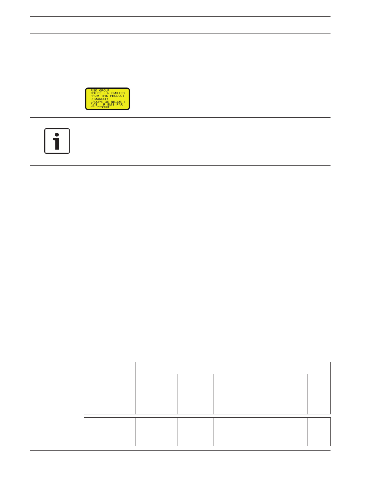
Notice!
This product has been tested according to standard IEC62471:2006 “Photobiological safety of
lamps and lamp systems”. The product emissions exceed the EXEMPT Group limit for both
Retinal Blue Light and Cornea/Lens infrared hazard as defined by IEC 62471:2006. The
product was found to meet the Risk Group 1 exposure limits for IR and White LEDs.
The IEC 62471 provides the methods to determine the risk group of any lamp or any product
incorporating a lamp. The risk groups in IEC 62471 indicate the degree of risk from potential
optical radiation hazards. The risk groups were developed based upon decades of lamp use
experience and the analysis of accidental injuries related to optical radiation emission.
EXEMPT Group – no optical hazard is considered reasonably foreseeable, even for
continuous, unrestricted use. Typical examples are most frosted incandescent lamps and
fluorescent lamps used in domestic applications.
Risk Group 1 – products are safe for most use applications, except for very prolonged
exposures where direct ocular exposures may be expected. An example of Risk Group 1 is a
domestic battery operated torch (flashlight).
Exposure Hazard Value (EHV) is a ratio of the Exposure Level (distance, exposure time) to
Exposure Limit Value (ELV). When EHV is greater than 1, the device has exceeded the
Exposure Limit Values for a particular Risk Group. The ELV is the level where optical radiation
to the eye or skin is not expected to result in adverse biological effects.
The Hazard Distance (HD) is the distance from the source at which the Exposure Level equals
the appropriate ELV. In other words, when EHV=1 for a particular Risk Group.
Regarding the Cornea / Lens infrared hazard of this product, the Exposure Hazard Value (EHV)
at a test distance of 200mm is 2.19 based on EXEMPT Group exposure limits. The EHV based
on Risk Group 1 limits is 0.386. The HD for the Exempt Group is 297 mm.
Regarding the Retinal Blue Light hazard, the EHV is 22.9 based on the EXEMPT Group
exposure limits and a test distance of 200 mm. The EHV based on Risk Group 1 limits is 0.266.
The HD for the Exempt Group is 2675 mm.
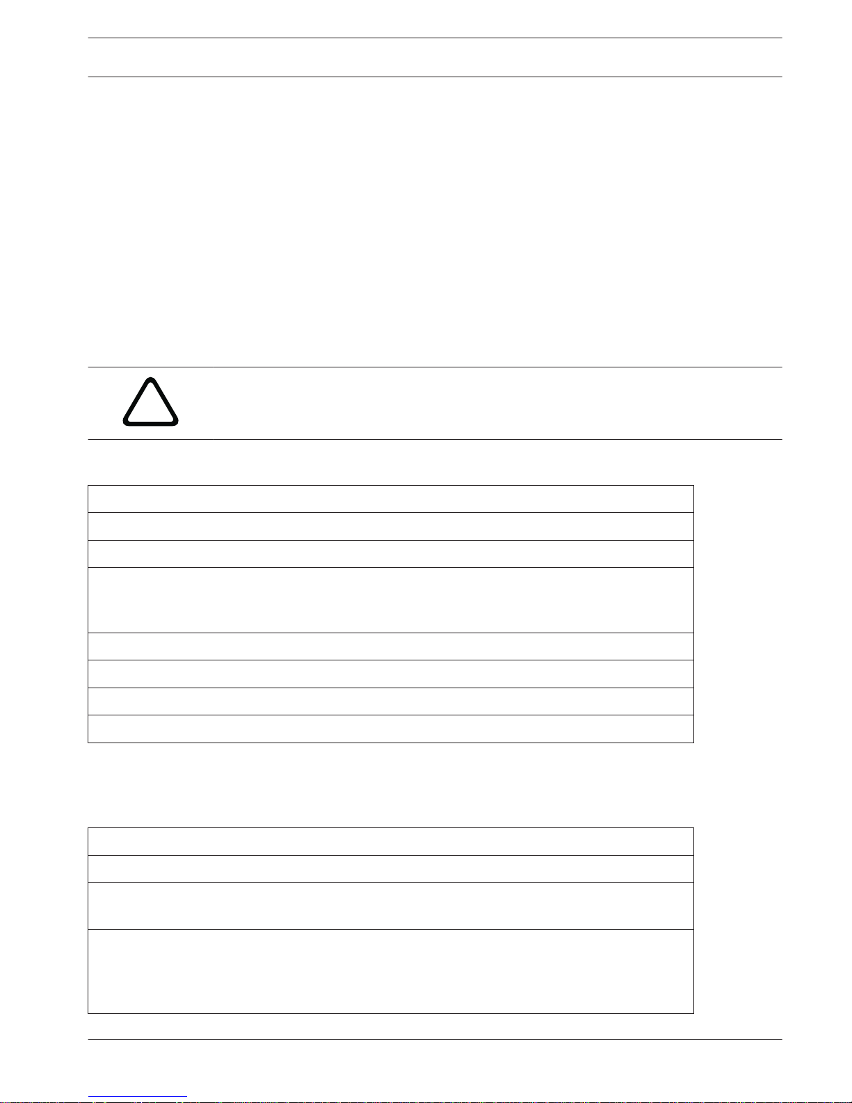
These values have been summarized in the table below:
Hazard
EXEMPT Group Limits Risk Group 1 Limits
t, duration d, distance EHV t, duration d, distance EHV
Cornea / Lens
Infrared Hazard
1000 s
Hazard
Distance
200 mm
279 mm
2.19 100 s 200 mm 0.386
Retinal Blue Light
Hazard
10,000 s
Hazard
Distance
200 mm
2675 mm
22.9 100s 200 mm 0.266
1
1.1
4 en | Safety
MIC IP starlight 7000 HD, MIC IP
dynamic 7000 HD
2015.12 | 3.0 | F.01U.291.520 Installation Manual Bosch Security Systems
Unpacking
– This equipment should be unpacked and handled with care. Check the exterior of the
packaging for visible damage. If an item appears to have been damaged in shipment,
notify the shipper immediately.
– Verify that all the parts listed in the Parts List below are included. If any items are
missing, notify your Bosch Security Systems Sales or Customer Service Representative.
– Do not use this product if any component appears to be damaged. Please contact Bosch
Security Systems in the event of damaged goods.
– The original packing carton is the safest container in which to transport the unit and must
be used if returning the unit for service. Save it for possible future use.
MIC7000 packaging is designed:
– to allow installers to configure the camera inside the shipping box.
– to provide a temporary table-top or desk-top stand.
!
Caution!
Take extra care lifting or moving MIC7000 cameras because of their weight (6.7 kg (14.7 lb)).
Parts List - Camera
One (1) MIC71xx or MIC72xx Camera
One (1) Quick Installation Guide
One (1) Document DVD
One (1) spanner tool [to remove and to attach the yoke caps in order to cant the camera if desired,
and to remove the access plug from the camera head when installing the optional illuminator
accessory (sold separately)]
One (1) base gasket
One (1) RJ45 coupler
Four (4) MAC address labels
One (1) ground screw
Additional Tools
The following table lists additional tools (not supplied by Bosch) that may be required to
install a MIC camera or its accessories:
1 Phillips-head screwdriver to secure the ground lug of the camera
1 Adjustable wrench or socket set to secure the base of the camera to mounting accessories
1 Torque wrench with 1/4 in. drive to use the supplied spanner tool for removing yoke caps and
blanking plugs if necessary
For canting cameras with Hex head screws:
1 Torque wrench with a 5 mm Hex bit (or T30 Torx bit) to remove/install bolts in the yoke arms
For canting cameras with Torx head screws:
1 Torque wrench with a Torx bit (T30 or T27) to remove/install bolts in the yoke arms
2
2.1
2.2
MIC IP starlight 7000 HD, MIC IP
dynamic 7000 HD
Unpacking | en 5
Bosch Security Systems Installation Manual 2015.12 | 3.0 | F.01U.291.520

Product Description
The MIC7000 camera is a high-performance, weatherproof, ruggedized, fully functional day/
night PTZ camera that has been designed to offer a reliable, robust, and high-quality
surveillance solution for extreme security applications.
Image control and quality are integral aspects of any PTZ camera, and the MIC7000 camera
delivers outstanding clarity and image detail. The camera has a professional-grade imaging
platform capable of delivering 720p50/60 or 1080p25/30 HD resolution in environments with
ambient light extremes.
Both camera variants--MIC IP starlight 7000 HD (MIC71xx) and MIC IP dynamic 7000 HD
(MIC72xx)--have a 30x optical zoom (12x digital) and flexible, field-selectable mounting
orientations (upright, inverted, or canted) to achieve the perfect field of view.
A long-life silicone wiper blade mounted on a spring-loaded arm is standard on all MIC
cameras.
The following table identifies the optional accessories for MIC cameras. Refer to the
datasheets of each accessory for details. Some accessories may not be available in all regions.
Accessories
Description Accessories Description
MIC-DCA-H
- MIC-DCA-HB
- MIC-DCA-HW
- MIC-DCA-HG
Hinged Deep Conduit Adapter in
Black
White
Grey
MIC-SCA
- MIC-SCA-BD
- MIC-SCA-WD
- MIC-SCA-GD
Shallow Conduit Adapter in
Black
White
Grey
MIC-CMB
- MIC-CMB-BD
- MIC-CMB-WD
- MIC-CMB-GD
Corner Mount Bracket in
Black
White
Grey
MIC-SPR
- MIC-SPR-BD
- MIC-SPR-WD
- MIC-SPR-GD
Spreader Plate in
Black
White
Grey
MIC-WMB
- MIC-WMB-BD
- MIC-WMB-WD
- MIC-WMB-GD
Wall Mount Bracket in
Black
White
Grey
MIC-ILx-100
- MIC-ILB-100
- MIC-ILW-100
- MIC-ILG-100
User-installable illuminator accessory
designed specifically for MIC7000
cameras, in
Black
White
Grey
MIC-PMB Pole Mount Bracket (stainless
steel only)
MICIP67-5PK MIC7000 IP67 Connector Kit
VJC-7000-90 VIDEOJET connect (Full-featured
network interface unit/power
supply)
NPD-6001A 60 W midspan [Not for use with the
illuminator accessory.]
VG4-A-PSU1, VG4A-PSU2
24 VAC (96 W) power supply NPD-9501A 95 W midspan
MIC-ALM-WAS-24 Alarm and washer interface
accessory unit
MIC-67SUNSHLD Sunshield (white only)
3
6 en | Product Description
MIC IP starlight 7000 HD, MIC IP
dynamic 7000 HD
2015.12 | 3.0 | F.01U.291.520 Installation Manual Bosch Security Systems
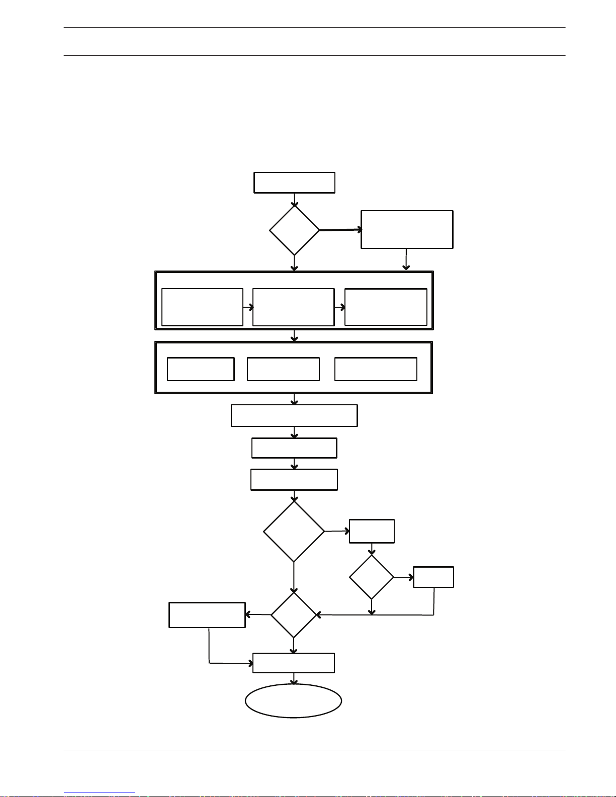
Overview of Installation Steps
The following figure identifies the steps to install a MIC7000 camera.
To install your MIC camera, follow these steps in sequence.
Note: Depending on your model of camera, your desired mounting location and orientation, as
well as your mounting brackets and chosen camera accessories, you may not need to
complete every step.
Determine system
configuration.
Operate the camera.
(Refer to Section 16.)
Connect network cable
(Refer to Section 10.)
Install
illuminator.
Install
sunshield.
Configure settings.
(Refer to Section 13.)
Alarm/Washer
Interface Unit
VIDEOJET connect
PSU
Cant the camera.
(Refer to Section 11.)
Install cabling between power
source and camera mounting site.
Install MIC Camera.
(Refer to Section 9.)
Power supply source
or PoE device
Connect and configure
camera in box or
on table-top stand.
(Refer to Sections 5 & 6.)
Install optional accessories.
(Refer to individual installation manuals.)
Select mounting
location and
orientation.
(Refer to Section 7.)
Install mounting
accessories and
conduit (if applicable).
Identify required
mounting accessories.
(Refer to Section 8.)
Identify Mounting Site Requirements.
Install a
sunshield?
YES
YES
NO
NO
Will
camera
be canted?
Pre-
configure
camera?
NO
YES
YES
NO
Install
optional
camera
access-
ories?
4
MIC IP starlight 7000 HD, MIC IP
dynamic 7000 HD
Overview of Installation Steps | en 7
Bosch Security Systems Installation Manual 2015.12 | 3.0 | F.01U.291.520
Configuration Programming in the Shipping Box
!
Caution!
Take extra care lifting or moving MIC7000 cameras because of their weight (6.7 kg (14.7 lb)).
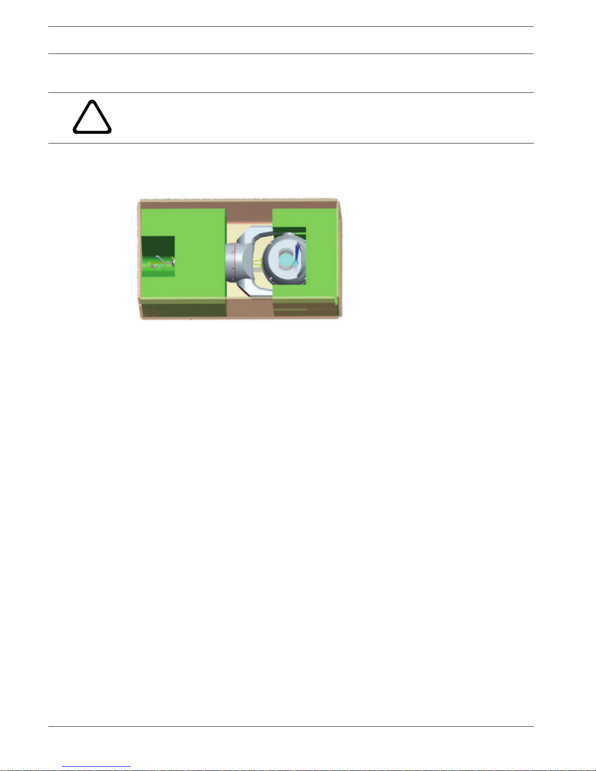
The camera packaging allows installers to connect the camera to the network and configure
the camera still in the box.
1. Remove the accessories box from the top, middle section of the box.
2. Supply power to the camera and Connect the Camera to the Network, page 20. Note that
the wiper moves one time across the camera window, and then returns to parked position.
3. Configure the camera. Refer to Configuration for details.
Note: Do not change the camera orientation to “Inverted” while the camera is still in the box.
The camera head must be free to rotate. If you must change the camera’s orientation to
“Inverted,” remove the camera from the box and configure it by following the steps in
Configuration Programming on a Temporary Table-top Stand, page 9.
4. Disconnect the wires/cables from the connectors in the base of the camera.
5
8 en | Configuration Programming in the Shipping Box
MIC IP starlight 7000 HD, MIC IP
dynamic 7000 HD
2015.12 | 3.0 | F.01U.291.520 Installation Manual Bosch Security Systems
Configuration Programming on a Temporary Table-top
Stand
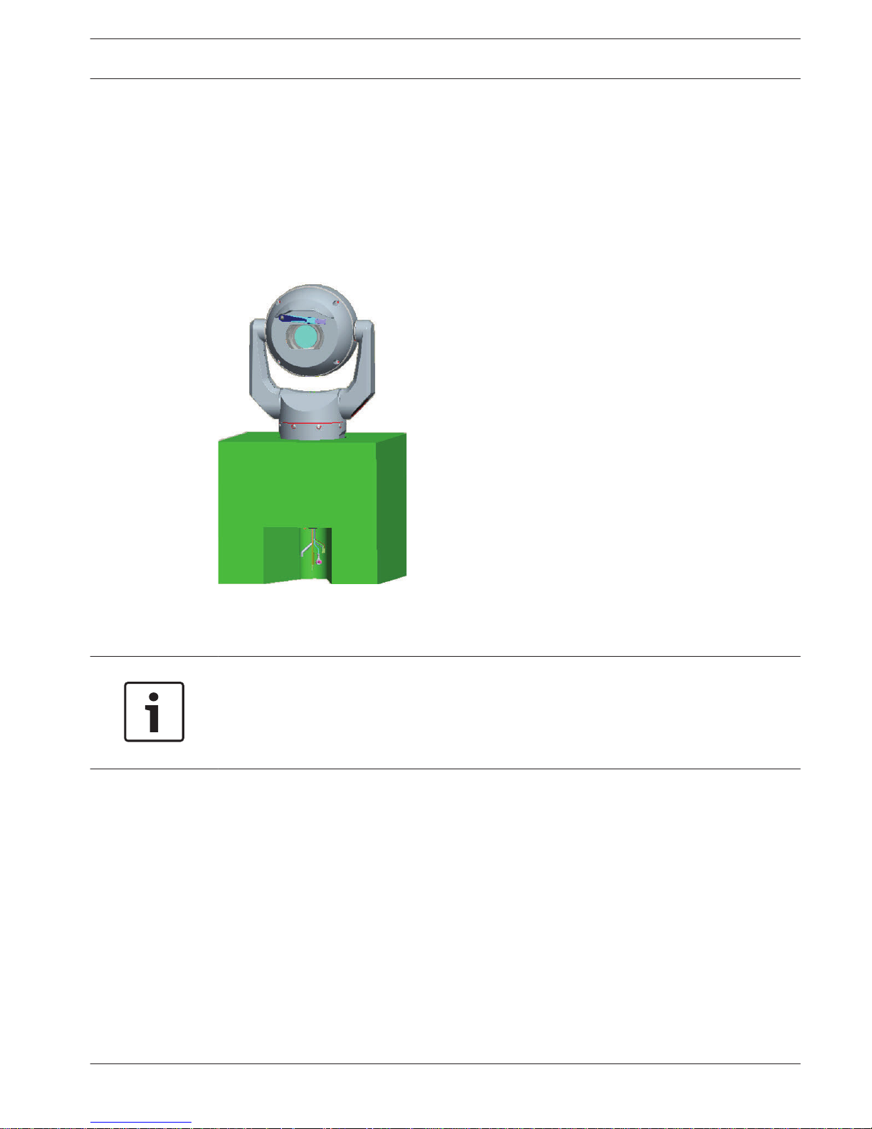
The camera (still in the foam) can stand temporarily on a flat, horizontal surface such as a
desk or a table during initial network connection and configuration.
1. Remove the accessories box from the top, middle section of the box.
2. Remove the camera, still in the foam, from the box. Place the camera upright on a flat,
horizontal surface.
3. Remove the foam covering the head of the camera.
4. Supply power to the camera and Connect the Camera to the Network, page 20. Note that
the wiper moves one time across the camera window, and then returns to parked position.
5. Configure the camera. Refer to Configuration for details.
Notice!
If you change the camera orientation to “Inverted” (from the Settings page of the web
browser: Advanced > Camera > Installer Menu > Orientation), then the camera head will
rotate automatically into inverted position (180°). Note that the visor will be near the top of
the body of the camera.
6. Disconnect the wires/cables from the connectors in the base of the camera.
6
MIC IP starlight 7000 HD, MIC IP
dynamic 7000 HD
Configuration Programming on a Temporary Table-top Stand | en 9
Bosch Security Systems Installation Manual 2015.12 | 3.0 | F.01U.291.520
Mounting Location and Mounting Orientation
Select the Mounting Location
MIC cameras are designed for easy installation in various locations such as directly onto
buildings and poles suitable to support CCTV equipment.
Select a secure installation location and mounting position for the device. Ideally, this is a
location where the device cannot be interfered with either intentionally or accidentally.
Ensure that the location has the appropriate clearance from power and lightning conductors,
in accordance with NEC725 and NEC800 (CEC Rule 16-224 and CEC Section 60).
Do not install the device near:
– Any heat sources
– Any overhead power lines, power circuits, or electrical lights, or where the device may
contact power lines, circuits, or lights
4 Ensure that the selected mounting surface is capable of supporting the combined weight
of the camera and mounting hardware (sold separately) under all expected conditions of
load, vibration, and temperature.
Notice!
MIC cameras must be secured to one of the following surfaces:
- Concrete (Solid/Cast)
- Concrete Masonry Unit (Concrete Block)
- Brick (all types)
- Metal (Steel/Aluminum, minimum 1/8-in. thick)
!
Caution!
Risk of lightning strikes
If the camera is installed in a highly exposed location where lightning strikes may occur, then
Bosch recommends installing a separate lightning conductor within 0.5 m (1.6 ft) of the
camera and at least 1.5 m (4.9 ft) higher than the camera. A good earth bonding connection
to the camera housing itself will provide protection against damage from secondary strikes.
The camera housing itself is constructed to cope with secondary strikes. If the correct
lightning protection is applied, then no damage to the internal electronics or camera should
result.
Installation in a damp environment (for example, near a coastline)
The fasteners and fixtures shipped with the camera help to keep the camera secure. Always
use Bosch-supplied screws and other fasteners when installing or performing maintenance on
the camera.
The camera head has three (3) plastic screws that are factory-installed to prevent corrosion in
units which do not have accessories installed on the camera head. If you install a sunshield or
an illuminator accessory, you will remove those screws and replace them with the screws that
ship with each accessory.
Before installation, inspect the metal parts of the camera for paint that is chipped or
otherwise damaged. If you notice any paint damage, touch up the damage with locally
available paint or sealants.
7
7.1
10 en | Mounting Location and Mounting Orientation
MIC IP starlight 7000 HD, MIC IP
dynamic 7000 HD
2015.12 | 3.0 | F.01U.291.520 Installation Manual Bosch Security Systems
Avoid installation practices that may bring the camera’s metal mountings in contact with
materials such as stainless steel. Such contacts can result in galvanic corrosion and degrade
the cosmetic appearance of the camera. These cosmetic damages caused by improper
installation are not covered by warranty as they do not affect the functionality of the camera.
Select the Mounting Orientation
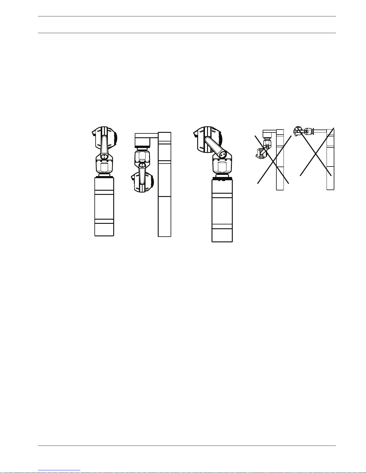
MIC Series cameras are designed to be mounted upright (straight up, 90°), inverted (straight
down, 90°), or canted upright (ball up, 45°). The tilt limits for the canted unit prevent it from
working properly if mounted ball down. See the figures below for illustrations of the correct
and the incorrect mounting orientations of MIC cameras.
Correct mounting orientation -
upright, inverted
Correct mounting orientation -
canted
Incorrect mounting orientation
Note the position of the visor when the camera is installed in inverted orientation. The visor is
close to the top of the pan shaft (the body of the MIC), instead of at the bottom of the
inverted camera.
Note: For canted cameras, ensure that your mounting location provides the necessary
clearance (370 mm (14.6 in.)) for the camera head to pan.
7.2
MIC IP starlight 7000 HD, MIC IP
dynamic 7000 HD
Mounting Location and Mounting Orientation | en 11
Bosch Security Systems Installation Manual 2015.12 | 3.0 | F.01U.291.520
 Loading...