

Bosch MIC7000, MIC-ILx-100 Quick Installation Manual
MIC7000 Illuminator
MIC-ILx-100
Quick Installation Guide
english
deutsch
français
中国语文 CHS
español
dansk
suomi
italiano
日本語
nederlands
norsk
polski
portuguese
русский
svensk


english
Table of contents 5
deutsch
Inhaltsverzeichnis 16
français
Table des matières 27
中国语文
CHS
目录 38
español
Tabla de contenidos 49
dansk
Indholdsfortegnelse 60
suomi
Sisällysluettelo 71
italiano
Sommario 82
日本語
目次 93
nederlands
Inhoudsopgave 104
norsk
Innholdsfortegnelse 115
MIC7000 Illuminator |
3
Bosch Security Systems 2014.08 | 1.2 | F.01U.306.503

polski
Spis treści 126
portuguese
Índice 137
русский
Содержание 148
svensk
Innehållsförteckning 159
4
| MIC7000 Illuminator
2014.08 | 1.2 | F.01U.306.503 Bosch Security Systems
Install the MIC7000
Illuminator
Parts List
1
One (1) MIC Illuminator accessory
1 One (1) spanner tool [to remove the access plug from the
camera head]
3 Three (3) M4x10 socket head Torx screws
1 One (1) Quick Installation Guide
Additional Tools Required
1 1/4 in. drive wrench to use with the spanner tool
1 Torx driver, T20, for M4 Torx screws
1 Phillips-head screwdriver, #2,
to remove factory-installed plastic screws from the camera
head
!
Warning!
IR emitted from this product.
Meets IEC 62471, Risk Group 1.
1
MIC7000 Illuminator Install the MIC7000 Illuminator | en
5
Bosch Security Systems 2014.08 | 1.2 | F.01U.306.503
Notice!
This product has been tested according to standard
IEC62471:2006 “Photobiological safety of lamps and
lamp systems”. The product emissions exceed the
EXEMPT Group limit for both Retinal Blue Light and
Cornea/Lens infrared hazard as defined by IEC
62471:2006. The product was found to meet the Risk
Group 1 exposure limits for IR and White LEDs.
Refer to the MIC7000 Operation Manual for complete
information on illumination safety.
Notice!
If the MIC camera will have both illuminator and
sunshield accessories, install the illuminator first.
Extreme low temperature MIC7000 models do not
support the illuminator.
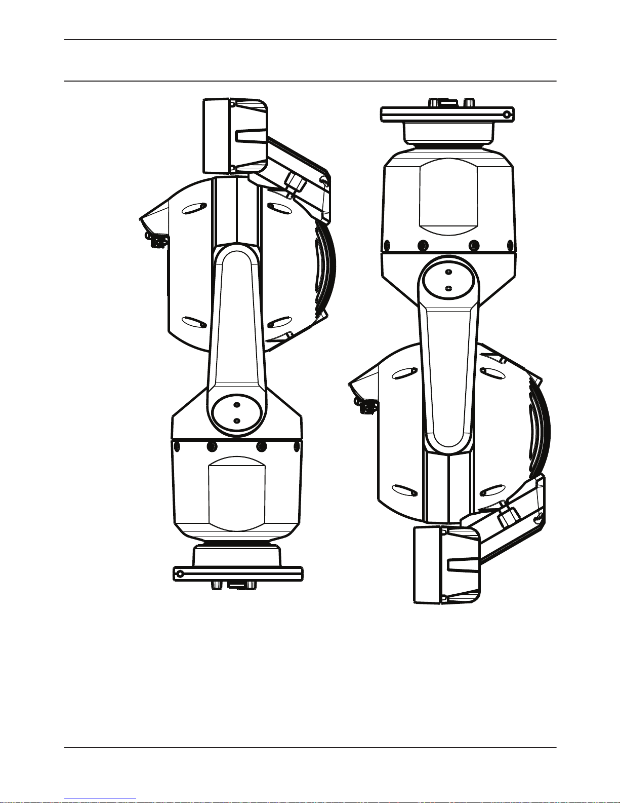
1. Mount the camera or stand it temporarily in the
packaging foam on a stable surface before proceeding.
(Refer to the Operation Manual.)
Note: If the camera will be mounted inverted, you must
rotate the tilt head before attaching the illuminator.
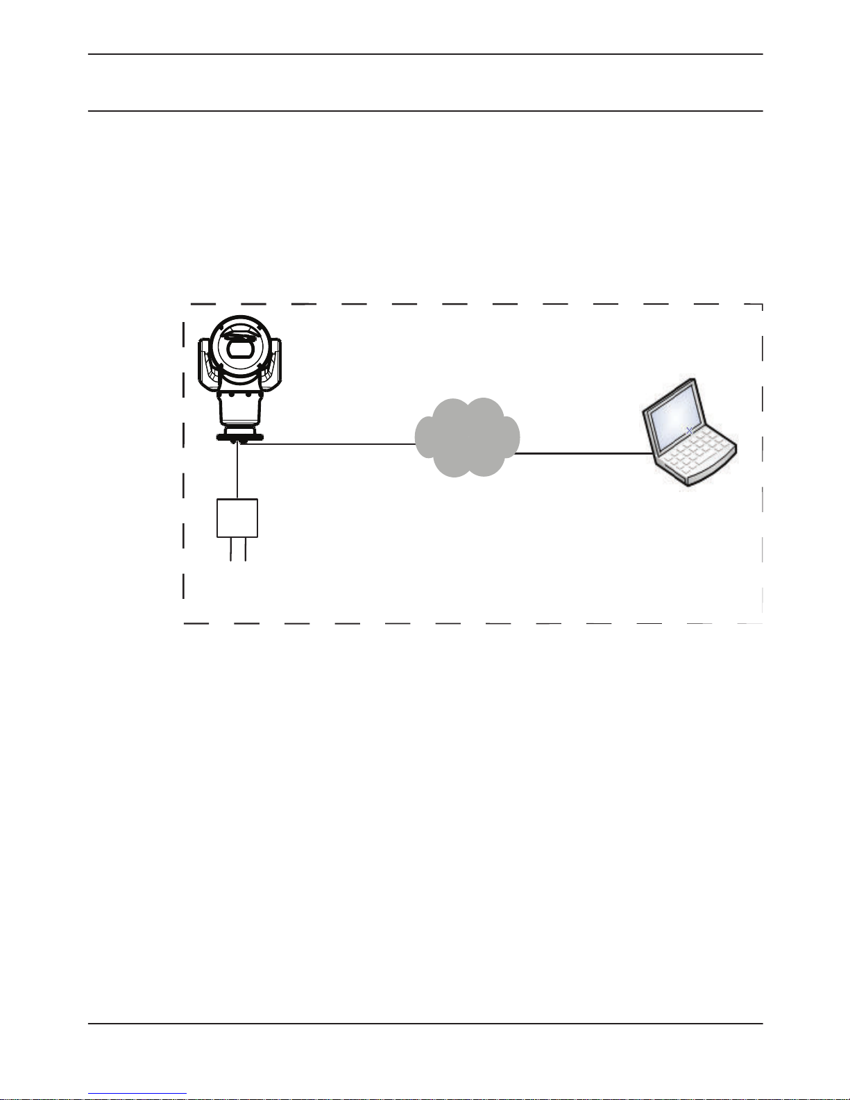
Apply power and connect to your network as illustrated
in the figure below.
6
en | Install the MIC7000 Illuminator MIC7000 Illuminator
2014.08 | 1.2 | F.01U.306.503 Bosch Security Systems
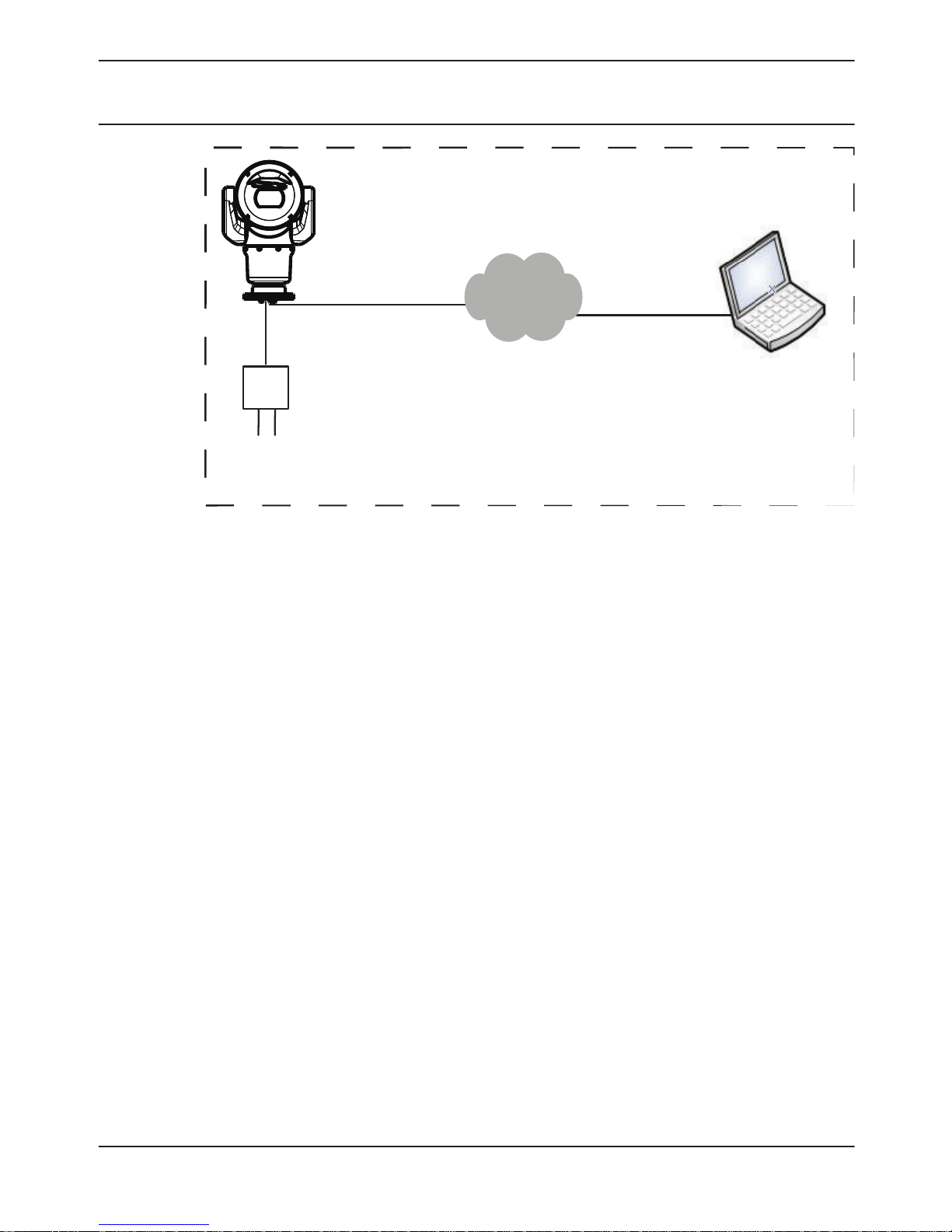
24 VAC
From the web browser, access the camera’s Settings
page. Select Advanced > Camera > Installer Menu >
Orientation, and then select “Inverted”. Click Set to
confirm the selection. The camera head will rotate
automatically into inverted position (180°).
Regardless of mounting orientation, the visor should
always be above the camera window.
MIC7000 Illuminator Install the MIC7000 Illuminator | en
7
Bosch Security Systems 2014.08 | 1.2 | F.01U.306.503

#2 Phillips
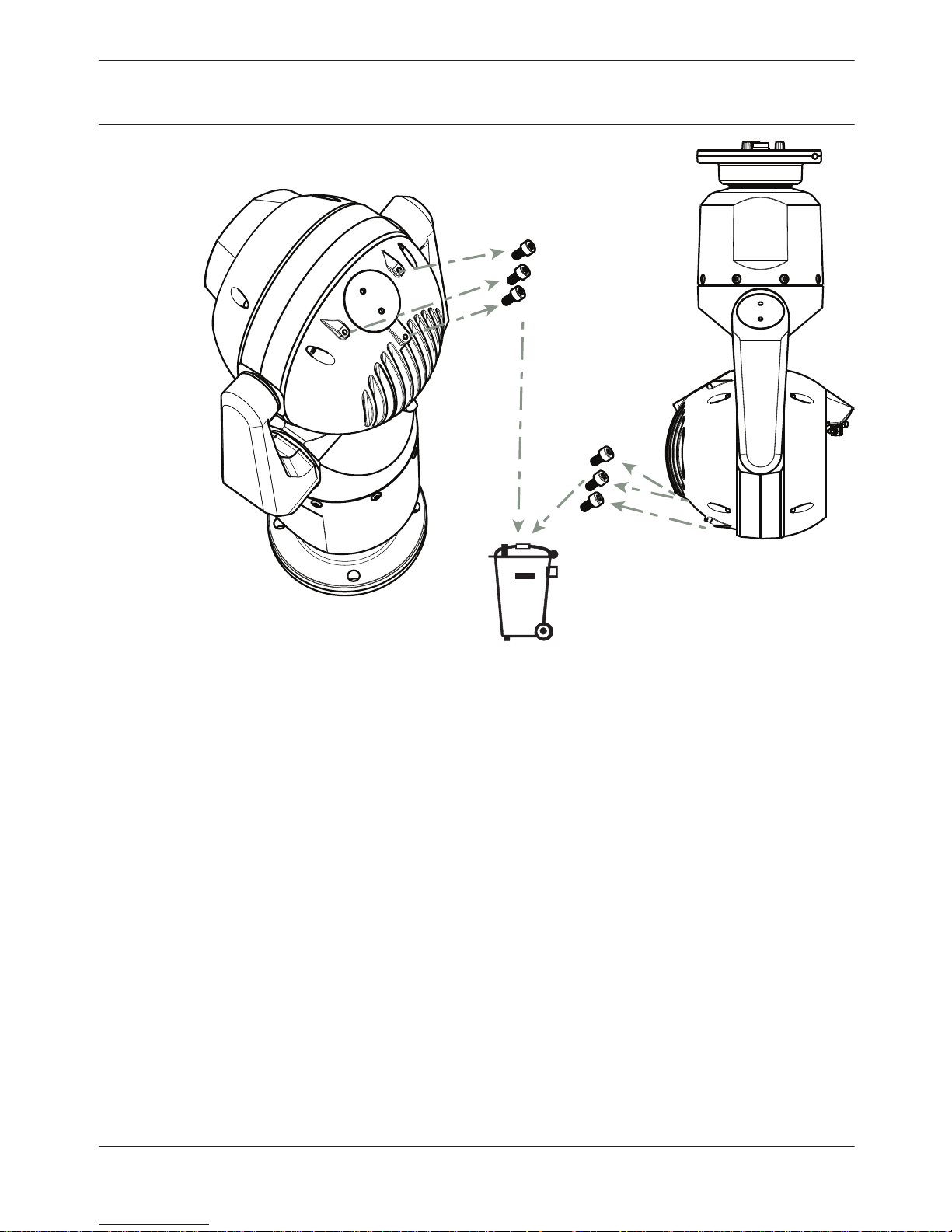
2. Remove and discard the three (3) plastic screws
surrounding the appropriate access port where the
illuminator will be installed.
8
en | Install the MIC7000 Illuminator MIC7000 Illuminator
2014.08 | 1.2 | F.01U.306.503 Bosch Security Systems
1/4”
1/4”
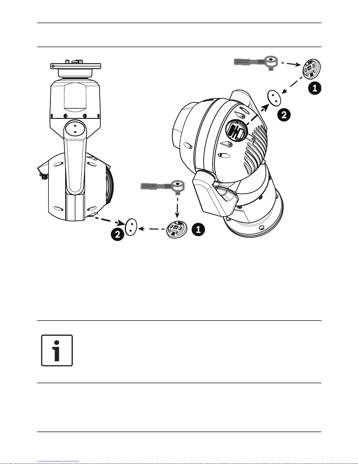
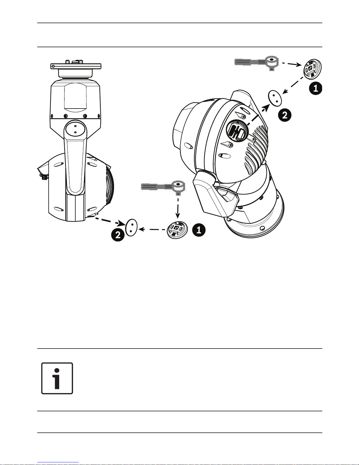
3. Remove the appropriate access plug from the camera
head, using a ¼ in. drive wrench (not supplied) with the
spanner tool (supplied). For upright cameras, remove
the plug near the visor. For inverted cameras, remove
the plug farther away from the visor.
Notice!
Risk of damage to camera!
Do not allow water or dirt to enter the open connector
port.
MIC7000 Illuminator Install the MIC7000 Illuminator | en
9
Bosch Security Systems 2014.08 | 1.2 | F.01U.306.503
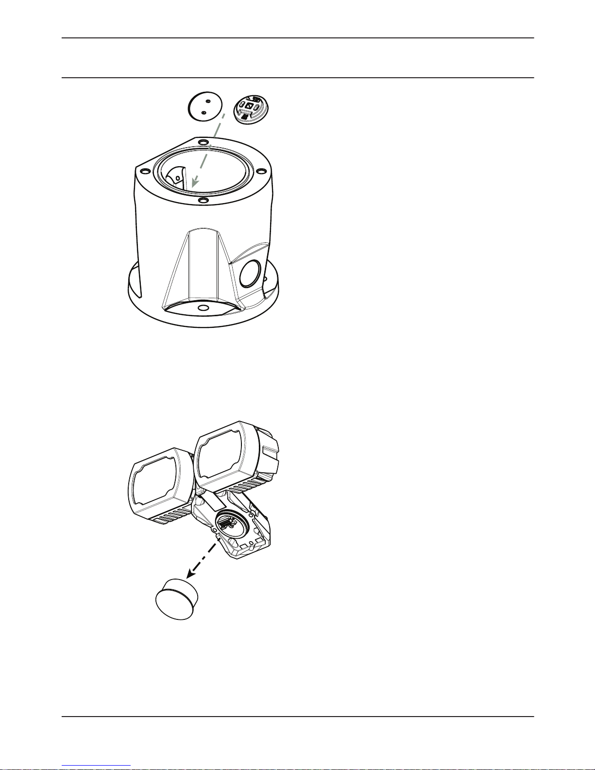
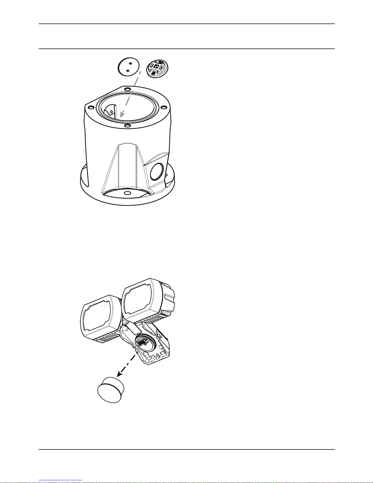
Bosch suggests storing the access plug and spanner
tool inside the DCA mount (or wall mount accessory) in
case it becomes necessary to remove the illuminator.
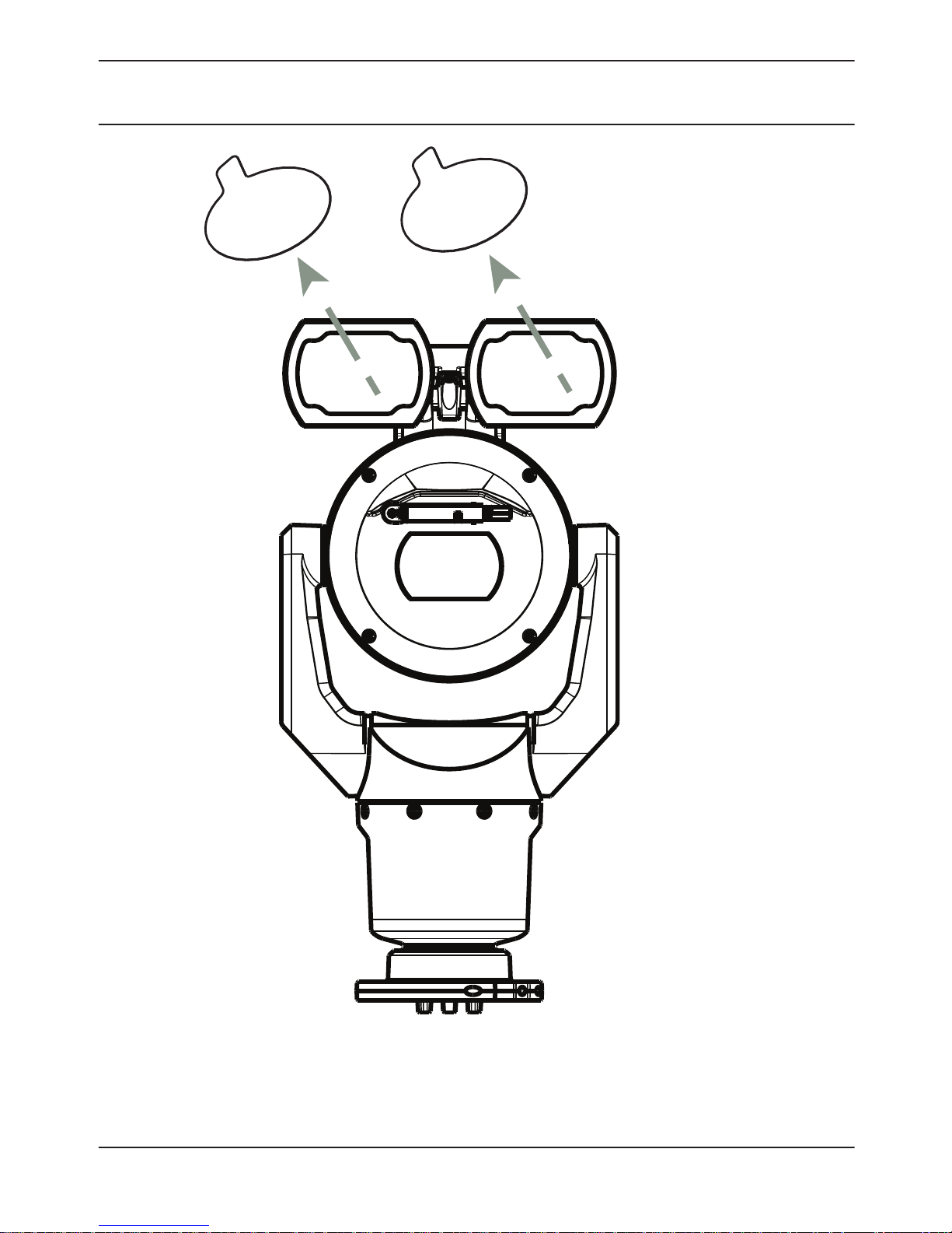
4. Remove the plastic cap from the illuminator
accessory. Discard.
10
en | Install the MIC7000 Illuminator MIC7000 Illuminator
2014.08 | 1.2 | F.01U.306.503 Bosch Security Systems
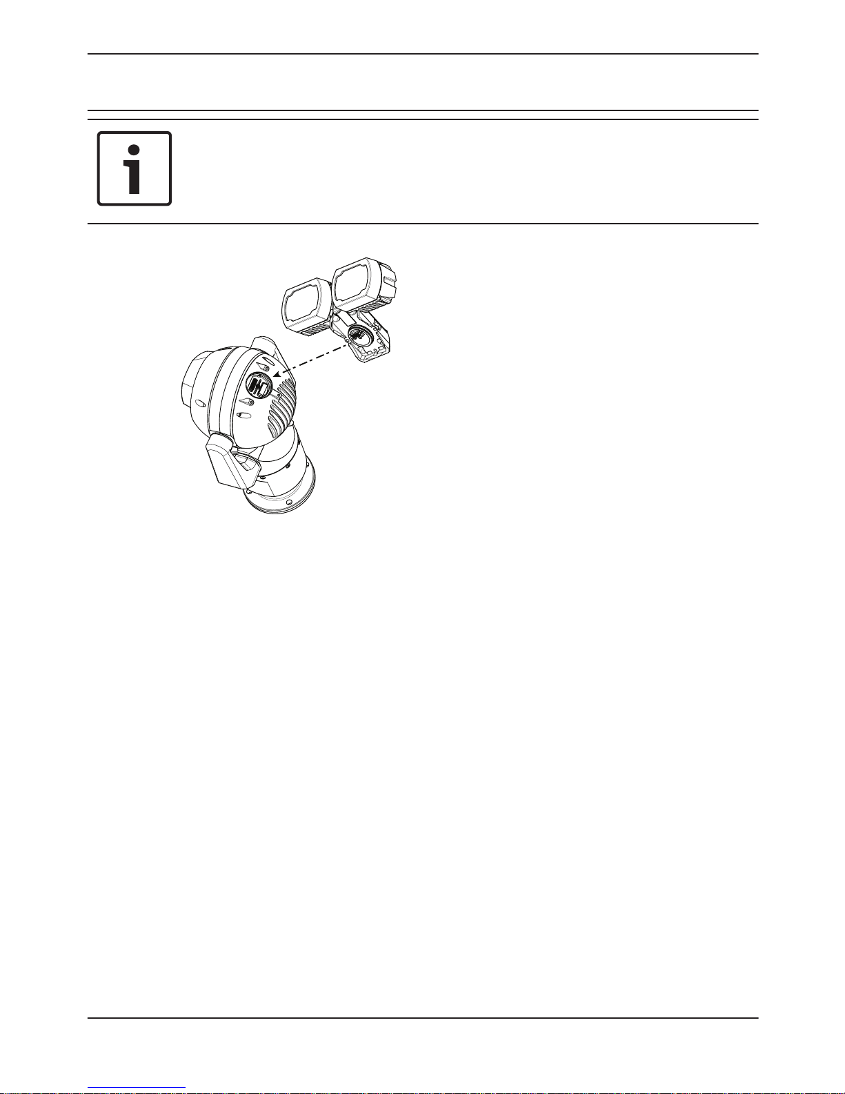
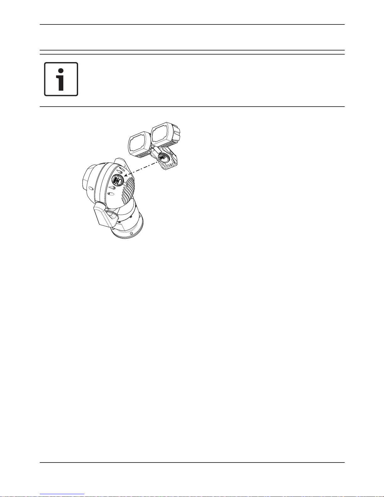
Notice!
Do not disturb the O-ring as you slide off the cap.
5. Align the illuminator over the access port and
carefully push into position on the camera head.
MIC7000 Illuminator Install the MIC7000 Illuminator | en
11
Bosch Security Systems 2014.08 | 1.2 | F.01U.306.503
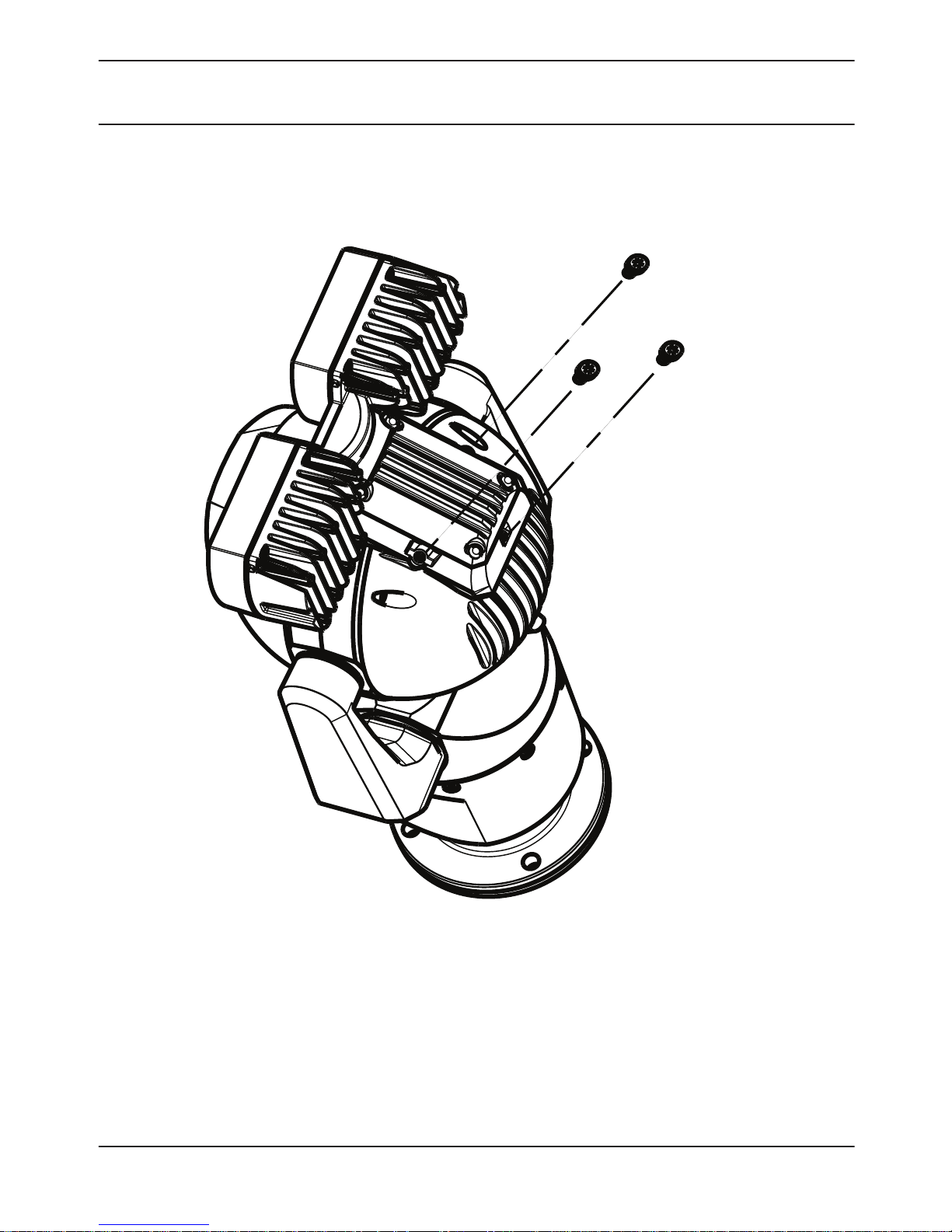
1.4 N m
(≈ 12 in. lb)
T20 Torx
6. Partially engage the threads of all three (3) screws.
Do not tighten any one screw completely at this point.
12
en | Install the MIC7000 Illuminator MIC7000 Illuminator
2014.08 | 1.2 | F.01U.306.503 Bosch Security Systems
Notice!
If you are also planning to install the MIC sunshield,
insert only the rear center screw to hold the illuminator
accessory in position until you install the sunshield.
Tighten the screw on one side by two (2) turns. Tighten
the screw on the other side by two (2) turns. Tighten
the center screw by two (2) turns. Repeat until all
screws are tight.
!
Warning!
Total engagement is not complete until you tighten all
three (3) screws.
MIC7000 Illuminator Install the MIC7000 Illuminator | en
13
Bosch Security Systems 2014.08 | 1.2 | F.01U.306.503

7. Remove the translucent film.
14
en | Install the MIC7000 Illuminator MIC7000 Illuminator
2014.08 | 1.2 | F.01U.306.503 Bosch Security Systems

8. Installation of the illuminator is complete.
MIC7000 Illuminator Install the MIC7000 Illuminator | en
15
Bosch Security Systems 2014.08 | 1.2 | F.01U.306.503
Montage des
MIC7000 Strahlers
Teileliste
1
Ein (1) MIC Strahler
1 Ein (1) Schraubenschlüssel [um den Zugangsstecker vom
Kamerakopf zu entfernen]
3 Drei (3) M4x10 Innensechskant-Torx-Schrauben
1 Ein (1) Schnellstartanleitung
Zusätzlich benötigtes Werkzeug
1 1/4-Zoll- Hakenschlüssel, zu verwenden mit dem
Schraubenschlüssel
1 Torx-Schraubendreher, T20, für M4 Torx-Schrauben
1 Kreuzschlitzschraubendreher, #2,
zur Entfernung der ab Werk montierten Plastikschrauben
vom Kamerakopf
!
Warnung!
Infrarotstrahlung wird von diesem Produkt abgegeben.
Entspricht IEC 62471, Gefahrengruppe 1.
1
16
de | Montage des MIC7000 Strahlers MIC7000 Illuminator
2014.08 | 1.2 | F.01U.306.503 Bosch Security Systems
Hinweis!
Dieses Produkt wurde gemäß der IEC-Norm
62471:2006, „Photobiologische Sicherheit von Lampen
und Lampensystemen“, geprüft. Die Emissionen des
Produkts überschreiten den Grenzwert der freien
Gruppe für die Gefährdung der Netzhaut durch
Blaulicht und die Gefährdung der Hornhaut/Linse durch
Infrarotlicht gemäß IEC 62471:2006. Das Produkt
erfüllt die Emissionsgrenzwerte der Risikogruppe 1 für
IR-LEDs und weiße LEDs.
Informationen zur Beleuchtungssicherheit finden Sie im
MIC7000 Benutzerhandbuch.
Hinweis!
Wenn Sie an der MIC-Kamera sowohl einen Strahler als
auch eine Sonnenblende montieren möchten, beginnen
Sie mit dem Strahler.
MIC7000 Modelle für extrem niedrige Temperaturen
unterstützen den Strahler nicht.
1. Montieren Sie die Kamera, oder stellen Sie sie
kurzzeitig auf den Verpackungsschaum, bevor Sie
fortfahren. (Siehe Benutzerhandbuch.)
MIC7000 Illuminator Montage des MIC7000 Strahlers | de
17
Bosch Security Systems 2014.08 | 1.2 | F.01U.306.503

Hinweis: Wenn die Kamera hängend montiert wird,
müssen Sie den Neigekopf drehen, bevor Sie den
Strahler anbringen. Stellen Sie die Stromversorgung
her, und schließen Sie Ihr Netzwerk an, wie in der
folgenden Abbildung gezeigt.
24 VAC
Greifen Sie vom Webbrowser auf die Einstellungsseite
der Kamera zu. Wählen Sie „Erweitert“ > „Kamera“ >
„Installationsmenü“ > „Ausrichtung“, und wählen Sie
dann „Hängend“. Klicken Sie auf Set (Setzen), um die
Auswahl zu bestätigen. Der Kamerakopf wird
automatisch in die hängende Position gedreht (180°).
Unabhängig von der Montageausrichtung sollte sich die
Schutzblende immer über dem Kamerafenster befinden.
18
de | Montage des MIC7000 Strahlers MIC7000 Illuminator
2014.08 | 1.2 | F.01U.306.503 Bosch Security Systems
#2 Phillips
2. Entfernen und entsorgen Sie die drei (3)
Plastikschrauben um den entsprechenden Zugriffs-
Port, an dem der Strahler angebracht wird.
MIC7000 Illuminator Montage des MIC7000 Strahlers | de
19
Bosch Security Systems 2014.08 | 1.2 | F.01U.306.503
1/4”
1/4”
3. Entfernen Sie den entsprechenden Zugangsstecker
vom Kamerakopf. Verwenden Sie dazu einen 1/4-Zoll
Hakenschlüssel (nicht im Lieferumfang enthalten) mit
dem Schraubenschlüssel (im Lieferumfang enthalten).
Entfernen Sie für aufrechte Kameras den Stecker an der
Schutzblende. Entfernen Sie für hängende Kameras den
Stecker, der weiter von der Schutzblende entfernt ist.
Hinweis!
Schützen Sie Ihre Kamera vor Beschädigungen!
Halten Sie den offenen Stecker-Port von Wasser und
Schmutz fern.
20
de | Montage des MIC7000 Strahlers MIC7000 Illuminator
2014.08 | 1.2 | F.01U.306.503 Bosch Security Systems
Bosch empfiehlt, den Zugangsstecker und das
Schraubenschlüssel in der DCA-Befestigung (oder im
Zubehör zur Wandmontage) aufzubewahren, falls es
nötig sein sollte, den Strahler zu entfernen.
4. Entfernen Sie die Plastikkappe vom Strahler.
Entsorgen Sie sie.
MIC7000 Illuminator Montage des MIC7000 Strahlers | de
21
Bosch Security Systems 2014.08 | 1.2 | F.01U.306.503
Hinweis!
Beschädigen Sie beim Entfernen der Kappe nicht den
O-Ring.
5. Richten Sie den Strahler über dem Zugriffs-Port aus,
und drücken Sie ihn vorsichtig auf dem Kamerakopf in
Position.
22
de | Montage des MIC7000 Strahlers MIC7000 Illuminator
2014.08 | 1.2 | F.01U.306.503 Bosch Security Systems

1.4 N m
(≈ 12 in. lb)
T20 Torx
6. Drehen Sie die Gewinde aller drei (3) Schrauben
teilweise fest. Drehen Sie noch keine der Schrauben
vollständig fest.
MIC7000 Illuminator Montage des MIC7000 Strahlers | de
23
Bosch Security Systems 2014.08 | 1.2 | F.01U.306.503
Hinweis!
Wenn Sie auch die MIC Sonnenblende montieren
möchten, stecken Sie nur die Schraube hinten in der
Mitte ein, um das Strahler in Position zu halten, bis Sie
die Sonnenblende montieren.
Ziehen Sie die Schraube auf einer Seite mit zwei (2)
Umdrehungen an. Ziehen Sie die Schraube auf der
anderen Seite mit zwei (2) Umdrehungen an. Ziehen Sie
die Schraube in der Mitte mit zwei (2) Umdrehungen an.
Wiederholen, bis alle Schrauben fest angezogen sind.
!
Warnung!
Stellen Sie sicher, dass alle drei (3) Schrauben fest
sitzen, um eine sichere Verschraubung zu
gewährleisten.
24
de | Montage des MIC7000 Strahlers MIC7000 Illuminator
2014.08 | 1.2 | F.01U.306.503 Bosch Security Systems
7. Entfernen Sie die durchsichtige Folie.
MIC7000 Illuminator Montage des MIC7000 Strahlers | de
25
Bosch Security Systems 2014.08 | 1.2 | F.01U.306.503
8. Die Montage des Strahlers ist abgeschlossen.
26
de | Montage des MIC7000 Strahlers MIC7000 Illuminator
2014.08 | 1.2 | F.01U.306.503 Bosch Security Systems

Installation du projecteur
MIC7000
Liste des pièces
1
Un (1) Accessoires pour éclairage et projecteurs MIC
1 Une (1) clé (pour retirer la fiche d'accès de la tête de la
caméra)
3 Trois (3) vis Torx M4 x 10 cruciformes
1 Un (1) Guide d'installation rapide
Outils supplémentaires requis
1 Entraînement 1/4 po. à utiliser avec la clé
1 Tournevis Torx, T20, pour les vis Torx M4
1 Tournevis cruciforme, #2,
pour retirer les vis en plastique préinstallées de la tête de la
caméra
!
Avertissement!
IR émis par ce produit.
Conforme aux normes IEC 62471, groupe de risque 1.
1
MIC7000 Illuminator Installation du projecteur MIC7000 | fr
27
Bosch Security Systems 2014.08 | 1.2 | F.01U.306.503
Remarque!
Ce produit a été testé selon la norme CEI62471:2006
« Sécurité photobiologique des lampes et des appareils
utilisant des lampes ». Les émissions du produit
dépassent la limite pour le groupe EXEMPT, aussi bien
pour la lumière bleue rétinienne que pour les risques
infrarouges pour la cornée/lentille définis par la norme
CEI 62471:2006. Le produit répond aux exigences du
Groupe de risque 1, limites d'exposition aux rayons
infrarouges et aux voyants lumineux LED blancs.
Reportez-vous au manuel d'utilisation MIC7000 pour de
plus amples informations sur la sécurité en matière
d'éclairage.
Remarque!
Si vous souhaitez équiper la caméra MIC d'un
projecteur et d'un pare-soleil, installez d'abord le
projecteur.
Il n'est pas possible d'installer un projecteur sur les
modèles de caméra MIC7000 destinés aux très basses
températures.
1. Montez la caméra ou placez-la sur une surface stable
dans sa mousse d'emballage avant de poursuivre.
(Reportez-vous au manuel d'utilisation)
28
fr | Installation du projecteur MIC7000 MIC7000 Illuminator
2014.08 | 1.2 | F.01U.306.503 Bosch Security Systems
Remarque : pour installer la caméra à l'envers, vous
devez faire pivoter la tête inclinable avant de fixer le
projecteur. Mettez le système sous tension et
connectez-vous à votre réseau, comme illustré dans la
figure ci-dessous.
24 VAC
Depuis votre navigateur Web, accédez à la page
Paramètres de la caméra. Sélectionnez Avancé >
Caméra > Menu Installateur > Orientation, puis
sélectionnez « Inversée ». Cliquez sur Set (Définir) pour
confirmer la sélection. La tête de la caméra va pivoter
automatiquement en position inversée (180 °).
Quel que soit le sens de montage, la visière doit
toujours se trouver au-dessus de la fenêtre de la
caméra.
MIC7000 Illuminator Installation du projecteur MIC7000 | fr
29
Bosch Security Systems 2014.08 | 1.2 | F.01U.306.503

#2 Phillips
2. Retirez et jetez les trois (3) vis en plastique
entourant le port d'accès où le projecteur sera
installé.
30
fr | Installation du projecteur MIC7000 MIC7000 Illuminator
2014.08 | 1.2 | F.01U.306.503 Bosch Security Systems
 Loading...