

Bosch MC 400 Installation Instructions For Skilled Labour
EMS 2
EMS plus
EMS
MC 400
[de] Installationsanleitung für das Fachhandwerk ................................................. 2
[en] Installation instructions for skilled labour .................................................... 11
[es] Manual de instalación para el técnico especializado...................................... 20
[fl] Installatiehandleiding voor de installateur ................................................... 29
[fr] Notice d’installation pour le professionnel................................................... 38
[it] Istruzioni per l'installazione per tecnico specializzato.................................... 48
[nl] Installatie-instructie voor de installateur ..................................................... 58
[pt] Instruções de instalação para técnicos especializados .................................. 68
[zh] уъӪઈᆹ㻵䈤᰾Җ ........................................................................... 77
6 720 809 449-00.1O
6 720 819 669 (2016/05)
2 | Inhaltsverzeichnis
Inhaltsverzeichnis
1 Symbolerklärung und Sicherheitshinweise . . . . . . . . . . . . . . . 2
1.1 Symbolerklärung . . . . . . . . . . . . . . . . . . . . . . . . . . . . . . . . 2
1.2 Allgemeine Sicherheitshinweise . . . . . . . . . . . . . . . . . . . 2
2 Angaben zum Produkt . . . . . . . . . . . . . . . . . . . . . . . . . . . . . . . . . 3
2.1 Wichtige Hinweise zur Verwendung . . . . . . . . . . . . . . . . . 3
2.2 Funktionsbeschreibung . . . . . . . . . . . . . . . . . . . . . . . . . . 3
2.2.1 Grundprinzip . . . . . . . . . . . . . . . . . . . . . . . . . . . . . . . . . . . 3
2.2.2 Zeitliche Begrenzungen . . . . . . . . . . . . . . . . . . . . . . . . . . 3
2.3 Regelungsstrategien . . . . . . . . . . . . . . . . . . . . . . . . . . . . . 4
2.3.1 Serielle Standard-Kaskade . . . . . . . . . . . . . . . . . . . . . . . . 4
2.3.2 Serielle optimierte Kaskade . . . . . . . . . . . . . . . . . . . . . . . 4
2.3.3 Serielle Kaskade mit Spitzenlastabdeckung . . . . . . . . . . 4
2.3.4 Parallele Kaskade . . . . . . . . . . . . . . . . . . . . . . . . . . . . . . . 4
2.3.5 Leistungsregelung . . . . . . . . . . . . . . . . . . . . . . . . . . . . . . . 4
2.3.6 Vorlauftemperaturregelung . . . . . . . . . . . . . . . . . . . . . . . 4
2.3.7 Pumpenvorlauf . . . . . . . . . . . . . . . . . . . . . . . . . . . . . . . . . 4
2.4 Kodierschalter einstellen . . . . . . . . . . . . . . . . . . . . . . . . . 5
2.5 Lieferumfang . . . . . . . . . . . . . . . . . . . . . . . . . . . . . . . . . . . 5
2.6 Technische Daten . . . . . . . . . . . . . . . . . . . . . . . . . . . . . . . 5
2.7 Ergänzendes Zubehör . . . . . . . . . . . . . . . . . . . . . . . . . . . . 5
2.8 Reinigung . . . . . . . . . . . . . . . . . . . . . . . . . . . . . . . . . . . . . . 5
3 Installation . . . . . . . . . . . . . . . . . . . . . . . . . . . . . . . . . . . . . . . . . . . 5
3.1 Installation . . . . . . . . . . . . . . . . . . . . . . . . . . . . . . . . . . . . . 5
3.2 Installation eines Temperaturfühlers an der
hydraulischen Weiche . . . . . . . . . . . . . . . . . . . . . . . . . . . 6
3.3 Elektrischer Anschluss . . . . . . . . . . . . . . . . . . . . . . . . . . . 6
3.3.1 Anschluss BUS-Verbindung und Temperaturfühler
(Kleinspannungsseite) . . . . . . . . . . . . . . . . . . . . . . . . . . . 6
3.3.2 Anschluss Spannungsversorgung, Pumpe und
Mischer (Netzspannungsseite) . . . . . . . . . . . . . . . . . . . . 6
3.3.3 Anschlusspläne mit Anlagenbeispielen . . . . . . . . . . . . . . 7
3.3.4 Überblick Anschlussklemmenbelegung . . . . . . . . . . . . . . 7
4 Inbetriebnahme . . . . . . . . . . . . . . . . . . . . . . . . . . . . . . . . . . . . . . . 8
4.1 Kodierschalter einstellen . . . . . . . . . . . . . . . . . . . . . . . . . 8
4.2 Inbetriebnahme der Anlage und des Moduls . . . . . . . . . . 8
4.2.1 Einstellungen bei Anlagen mit einem Kaskadenmodul
im BUS-System . . . . . . . . . . . . . . . . . . . . . . . . . . . . . . . . . 8
4.2.2 Einstellungen bei Anlagen mit 2 oder mehr
Kaskadenmodulen im BUS-System . . . . . . . . . . . . . . . . . 8
4.3 Zustandsanzeige für Wärmeerzeuger/
untergeordnete Kaskadenmodule am
übergeordneten Kaskadenmodul . . . . . . . . . . . . . . . . . . 8
4.4 Zustandsanzeige der Wärmeerzeuger am
untergeordneten Kaskadenmodul . . . . . . . . . . . . . . . . . . 8
4.5 Menü Einstellungen Kaskade . . . . . . . . . . . . . . . . . . . . . . 9
4.6 Menü Diagnose . . . . . . . . . . . . . . . . . . . . . . . . . . . . . . . . . 9
5 Störungen beheben . . . . . . . . . . . . . . . . . . . . . . . . . . . . . . . . . . 10
5.1 Betriebsanzeige an einzeln installiertem oder
übergeordnetem Kaskadenmodul . . . . . . . . . . . . . . . . .10
5.2 Betriebsanzeige an untergeordnetem
Kaskadenmodul . . . . . . . . . . . . . . . . . . . . . . . . . . . . . . . 10
1 Symbolerklärung und Sicherheitshinweise
1.1 Symbolerklärung
Warnhinweise
Warnhinweise im Text werden mit einem Warndreieck
gekennzeichnet.
Zusätzlich kennzeichnen Signalwörter die Art und Schwere
der Folgen, falls die Maßnahmen zur Abwendung der
Gefahr nicht befolgt werden.
Folgende Signalwörter sind definiert und können im vorliegenden Dokument verwendet sein:
• HINWEIS bedeutet, dass Sachschäden auftreten können.
• VORSICHT bedeutet, dass leichte bis mittelschwere Personenschä-
den auftreten können.
• WARNUNG bedeutet, dass schwere bis lebensgefährliche Perso-
nenschäden auftreten können.
• GEFAHR bedeutet, dass schwere bis lebensgefährliche Personen-
schäden auftreten werden.
Wichtige Informationen
Wichtige Informationen ohne Gefahren für Menschen
oder Sachen werden mit dem nebenstehenden Symbol
gekennzeichnet.
Weitere Symbole
Symbol Bedeutung
▶ Handlungsschritt
Æ Querverweis auf eine andere Stelle im Dokument
• Aufzählung/Listeneintrag
– Aufzählung/Listeneintrag (2. Ebene)
Tab. 1
1.2 Allgemeine Sicherheitshinweise
Diese Installationsanleitung richtet sich an Fachleute für Wasserinstallationen, Heizungs- und Elektrotechnik.
▶ Installationsanleitungen (Wärmeerzeuger, Module, usw.) vor der
Installation lesen.
▶ Sicherheits- und Warnhinweise beachten.
▶ Nationale und regionale Vorschriften, technische Regeln und Richtli-
nien beachten.
▶ Ausgeführte Arbeiten dokumentieren.
Bestimmungsgemäße Verwendung
▶ Produkt ausschließlich zur Regelung von Heizungsanlagen mit Kaska-
densystemen verwenden. In einem Kaskadensystem werden mehre-
re Wärmeerzeuger genutzt, um eine höhere Wärmeleistung zu
erreichen.
Jede andere Verwendung ist nicht bestimmungsgemäß. Daraus resultie-
rende Schäden sind von der Haftung ausgeschlossen.
Installation, Inbetriebnahme und Wartung
Installation, Inbetriebnahme und Wartung darf nur ein zugelassener
Fachbetrieb ausführen.
▶ Produkt nicht in Feuchträumen installieren.
▶ Nur Originalersatzteile einbauen.
6 Umweltschutz/Entsorgung . . . . . . . . . . . . . . . . . . . . . . . . . . . 10
MC 4006 720 819 669 (2016/05)

Angaben zum Produkt | 3
Elektroarbeiten
Elektroarbeiten dürfen nur Fachleute für Elektroinstallationen ausführen.
▶ Vor Elektroarbeiten:
– Netzspannung (allpolig) spannungsfrei schalten und gegen Wie-
dereinschalten sichern.
– Spannungsfreiheit feststellen.
▶ Produkt benötigt unterschiedliche Spannungen.
Kleinspannungsseite nicht an Netzspannung anschließen und umgekehrt.
▶ Anschlusspläne weiterer Anlagenteile ebenfalls beachten.
Übergabe an den Betreiber
Weisen Sie den Betreiber bei der Übergabe in die Bedienung und die Betriebsbedingungen der Heizungsanlage ein.
▶ Bedienung erklären – dabei besonders auf alle sicherheitsrelevanten
Handlungen eingehen.
▶ Darauf hinweisen, dass Umbau oder Instandsetzungen nur von ei-
nem zugelassenen Fachbetrieb ausgeführt werden dürfen.
▶ Auf die Notwendigkeit von Inspektion und Wartung für den sicheren
und umweltverträglichen Betrieb hinweisen.
▶ Installations- und Bedienungsanleitungen zur Aufbewahrung an den
Betreiber übergeben.
Schäden durch Frost
Wenn die Anlage nicht in Betrieb ist, kann sie einfrieren:
▶ Hinweise zum Frostschutz beachten.
▶ Anlage immer eingeschaltet lassen, wegen zusätzlicher Funktionen,
z. B. Warmwasserbereitung oder Blockierschutz.
▶ Auftretende Störung umgehend beseitigen.
2 Angaben zum Produkt
Das Modul dient zum Regeln von Kaskadensystemen. Ein Kaskadensystem ist ein Heizungssystem, in dem mehrere Wärmeerzeuger genutzt
werden, um eine größere Wärmeleistung zu erhalten. Siehe dazu z. B.
Schaltplan auf Seite 90.
• Das Modul dient zur Ansteuerung der Wärmeerzeuger.
• Das Modul dient zur Erfassung der Außen-, Vorlauf und Rücklauftemperatur.
• Konfiguration des Kaskadensystems mit einer Bedieneinheit mit
BUS-Schnittstelle EMS 2 / EMS plus (nicht mit allen Bedieneinheiten
möglich).
Die Kombinationsmöglichkeiten der Module sind aus den Anschlussplänen ersichtlich.
2.1 Wichtige Hinweise zur Verwendung
Das Modul kommuniziert über eine EMS 2 / EMS plus Schnittstelle mit
anderen EMS 2 / EMS plus-fähigen BUS-Teilnehmern.
Wenn bei Wärmeerzeugern mit drehzahlgeregelter Pumpe
beim Brennerstart die Drehzahl zu gering ist, können hohe
Temperaturen und häufiges Brennertakten auftreten.
▶ Wenn möglich, Pumpe auf Ein/Aus-Betrieb mit
100 % Leistung konfigurieren, sonst minimale Pumpenleistung auf höchstmöglichen Wert einstellen.
• Das Modul kann an Bedieneinheiten mit BUS-Schnittstelle EMS 2 /
EMS plus (Energie-Management-System) angeschlossen werden.
Alternativ kann über die 0-10V-Schnittstelle am Modul eine externe
Leistungs- oder Temperaturanforderung angeschlossen werden.
• Das Modul kommuniziert nur mit Wärmeerzeugern mit EMS, EMS 2,
EMS plus und 2-Draht-BUS (HTIII) (außer Wärmeerzeuger der
Produktserien GB112, GB132, GB135, GB142, GB152).
• Nur Wärmeerzeuger eines Herstellers in der Anlage anschließen.
• Nur Wärmeerzeuger mit Energieträger Gas oder nur Wärmeerzeuger
mit Energieträger Öl in einer Anlage verwenden (keine Wärmepumpen mit BUS-Schnittstelle EMS 2 / EMS plus erlaubt).
• Der Installationsraum muss für die Schutzart gemäß den technischen
Daten des Moduls geeignet sein.
• Wenn ein Warmwasserspeicher direkt an einem Wärmeerzeuger angeschlossen ist:
– Der Systemregler oder 0-10 V Regler zeigt keine Informationen
zum Warmwassersystem an und hat keinen Einfluss auf die
Warmwasserbereitung.
– Es wird empfohlen, bei direkter Warmwasserbereitung einen
Speicher kleiner 400 Liter zu verwenden.
– Warmwasser einschließlich thermischer Desinfektion wird direkt
vom Wärmeerzeuger gesteuert.
– Thermische Desinfektion muss ggf. manuell überwacht werden.
Anleitung des Wärmeerzeugers beachten.
– Wenn die Überwachung der thermischen Desinfektion am Gerät
nicht möglich ist, keinen Warmwasserspeicher direkt an einem
Wärmeerzeuger anschließen.
2.2 Funktionsbeschreibung
2.2.1 Grundprinzip
Das Modul moduliert die Gesamtleistung der Kaskade abhängig von der
Temperaturdifferenz zwischen Vorlauftemperatur (an der hydraulischen
Weiche) und Systemsolltemperatur. Dazu werden Geräte nacheinander
zu- oder abgeschaltet. Die Geräte werden immer über Leistungsvorgabe
moduliert und erhalten als Temperatursollwert jeweils die maximal mögliche Solltemperatur. Bevor ein Gerät zugeschaltet wird, aktiviert das
Modul für 2 Minuten die Heizungspumpe, um das Gerät auf Betriebstemperatur zu bringen.
Jedes Gerät verursacht beim zu- oder abschalten einen erheblichen
Leistungssprung. Das Modul verwendet das vorher eingeschaltete Gerät, um den Leistungssprung zu verringern.
Dazu moduliert das Modul das erste Gerät zunächst bis zur Maximalleistung. Wenn dann ein weiteres Gerät eingeschaltet wird, senkt es gleichzeitig die Leistung des ersten Gerätes ab. Dadurch verursacht das
Zweite keinen Sprung in der Gesamtleistung. Bei weiterem Leistungsbedarf erhöht das Modul dann wieder die Leistung des ersten Gerätes. Das
Zweite bleibt bei Minimalleistung. Erst, wenn das erste Gerät wieder die
Maximalleistung erreicht, erfolgt die Modulation am zweiten Gerät. Bei
entsprechendem Leistungsbedarf wird dies fortgesetzt, bis alle Geräte
mit Maximalleistung laufen.
Wenn die gelieferte Leistung zu groß ist, verringert das Modul die Leistung des zuletzt zugeschalteten Gerätes bis zur Minimalleistung. Danach
wird das davor gestartete Gerät (das noch mit Maximalleistung läuft)
moduliert, bis es um die verbliebene Leistung des letzten Gerätes reduziert wurde. Erst dann wird das letzte Gerät abgeschaltet und gleichzeitig das Vorletzte wieder auf Maximalleistung gesetzt. Damit wird ein
sprunghaftes Absenken der Gesamtleistung vermieden. Wenn die Betriebstemperatur zu hoch bleibt, wird dies fortgesetzt, bis alle Geräte
abgeschaltet sind. Wenn die Wärmeanforderung endet, werden alle Geräte gleichzeitig abgeschaltet.
2.2.2 Zeitliche Begrenzungen
Wenn mehr Leistung benötigt wird als ein Wärmeerzeuger liefern kann
oder die Temperatur unter der Solltemperatur
verfügbare Wärmeerzeuger erst nach einer definierten Zeit
zugeschaltet.
1) Tolerierte Untertemperatur, Einstellbereich 0-10 K, Werkseinstellung 5 K
(wird bei Leistungsregelung nicht verwendet)
2) Anlaufverzögerung Folgegerät, Einstellbereich 0-15 Minuten, Werkseinstellung
6 Minuten
1)
ist, wird der nächste
2)
vom Modul
6 720 819 669 (2016/05)MC 400
4 | Angaben zum Produkt
Nach dem Start eines weiteren Wärmeerzeugers wartet das Modul
1½ Minuten, bis eine weitere Leistungsanhebung erfolgt. Dies verhindert weitestgehend ein Überschwingen der Temperatur.
Dieses Grundprinzip gilt für die Funktionen mit Kodierung 1 bis 4 und 8
bis 9. Das Modul regelt bei diesen Funktionen immer auf die Solltemperatur im System, und die tolerierte Unter-/ und Übertemperatur dient als
Schaltdifferenz für die Wärmeerzeuger.
2.3 Regelungsstrategien
2.3.1 Serielle Standard-Kaskade
Die angeschlossenen Wärmeerzeuger/Module werden entsprechend
der Verdrahtung zu- oder abgeschaltet.
Z. B. wird der Wärmeerzeuger an Anschlussklemme BUS1 als Erster, der
Wärmeerzeuger an Anschlussklemme BUS2 als Zweiter usw. zugeschaltet.
Wenn die Wärmeerzeuger abgeschaltet werden, ist die Reihenfolge umgekehrt. Der Wärmeerzeuger, der als Letzter zugeschaltet wurde, wird
zu erst wieder abgeschaltet.
Die Regelung berücksichtigt dabei, dass die Leistung beim zu- oder Abschalten eines Wärmeerzeugers sprunghaft ansteigt oder abfällt.
2.3.2 Serielle optimierte Kaskade
Ziel dieser Regelungsstrategie ist, die Wärmeerzeuger mit möglichst
gleichen Brennerlaufzeiten zu betreiben.
Die angeschlossenen Wärmeerzeuger werden entsprechend der Brennerlaufzeit zu- oder abgeschaltet. Die Brennerlaufzeiten werden alle
24 Stunden verglichen und die Reihenfolge somit neu bestimmt.
Der Wärmeerzeuger mit der kürzesten Brennerlaufzeit wird zu erst, der
mit der längsten zu letzt zugeschaltet.
Wenn die Wärmeerzeuger abgeschaltet werden, ist die Reihenfolge umgekehrt. Der Wärmeerzeuger, der als Letzter zugeschaltet wurde, wird
zu erst wieder abgeschaltet.
Die Regelung berücksichtigt dabei, dass die Leistung beim Zu- oder Abschalten eines Wärmeerzeugers sprunghaft ansteigt oder abfällt
(Æ Kap. 2.2.1).
2.3.3 Serielle Kaskade mit Spitzenlastabdeckung
Diese Regelungsstrategie ist sinnvoll, wenn die Heizlast über längere
Zeit gleichmäßig (Grundlast) und kurzzeitig höher (Spitzenlast) ist.
Die Wärmeerzeuger an den Anschlussklemmen BUS1 und BUS2 decken
dabei die Grundlast. Die Wärmeerzeuger an den Anschlussklemmen
BUS3 und BUS4 werden zugeschaltet, um den Energiebedarf bei Spitzenlast zu decken.
Die Wärmeerzeuger an den Anschlussklemmen BUS3 und BUS4 werden
zugeschaltet, wenn die geforderte Vorlauftemperatur über einen einstellbaren Grenzwert steigt oder die Außentemperatur unter einen einstellbaren Grenzwert fällt.
Wenn die Wärmeerzeuger abgeschaltet werden, ist die Reihenfolge umgekehrt. Der Wärmeerzeuger, der als Letzter zugeschaltet wurde, wird
zu erst wieder abgeschaltet.
Die Regelung berücksichtigt dabei, dass die Leistung beim Zu- oder Abschalten eines Wärmeerzeugers sprunghaft ansteigt oder abfällt
(Æ Kap. 2.2.1).
2.3.4 Parallele Kaskade
Diese Regelungsstrategie sollte verwendet werden, wenn die Wärmeerzeuger einen ähnlichen Modulationsgrad haben.
Wenn an einem zugeschalteten Gerät 68 % der Leistung erreicht sind,
wird das Nächste zugeschaltet.
Die Wärmeerzeuger werden dadurch mit annähernd gleichen Brennerlaufzeiten betrieben, da in der Regel dabei alle Wärmeerzeuger gleichzeitig in Betrieb sind. Wenn alle Wärmeerzeuger zugeschaltet sind,
werden sie in gleichem Maß modulierend betrieben.
2.3.5 Leistungsregelung
Diese Regelungsstrategie findet Anwendung, wenn die Heizungsanlage
über eine Gebäudeleittechnik mit einem 0-10 V-Reglerausgang geregelt
wird.
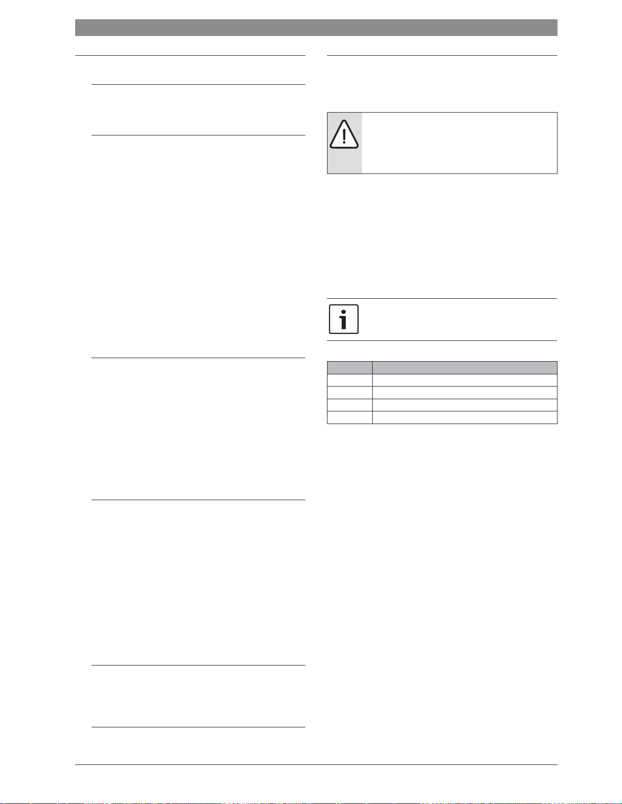
P / %
100
10
1
1,5 10
U / V
6 720 809 449-21.1O
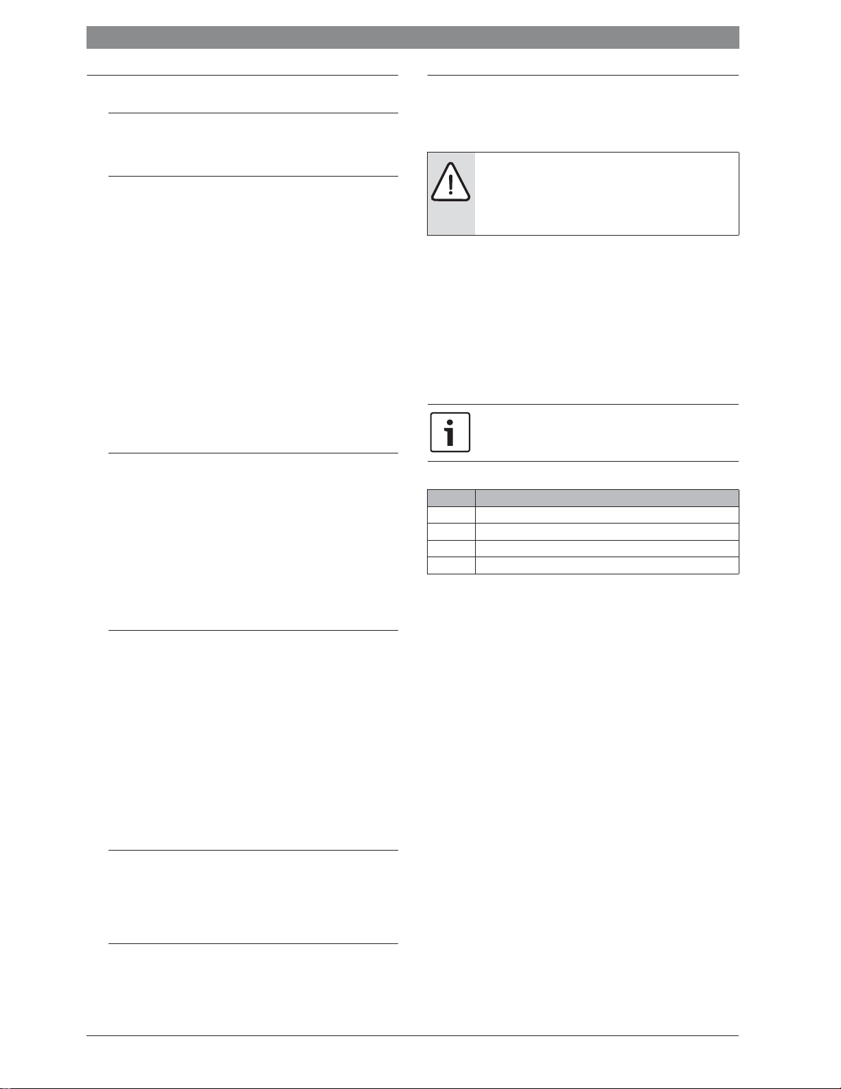
Bild 1 Linearer Zusammenhang zwischen 0-10 V-Signal (U in Volt)
und angeforderter Leistung P (in Prozent bezogen auf die
maximale Leistung der Anlage)
Die angeschlossenen Wärmeerzeuger werden entsprechend der angeforderten Leistung gemäß Kodierung des Moduls wie bei serieller Standard oder serieller optimierter Kaskade zu- und abgeschaltet.
2.3.6 Vorlauftemperaturregelung
Diese Regelungsstrategie findet Anwendung, wenn die Heizungsanlage
über eine Gebäudeleittechnik mit einem 0-10 V-Reglerausgang geregelt
wird.
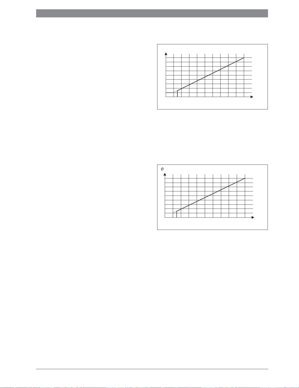
/ °C
90
20
1
1,5 10
Bild 2 Linearer Zusammenhang zwischen 0-10V-Signal (U in Volt) und
angeforderter Vorlauftemperatur - (in °C bezogen auf den
Bereich minimale Vorlauftemperatur bis maximale Vorlauftemperatur [Grundeinstellung 20 °C bis 90 °C])
Die angeschlossenen Wärmeerzeuger werden entsprechend der angeforderten Vorlauftemperatur gemäß Kodierung des Moduls wie bei serieller Standard oder serieller optimierter Kaskade zu- und abgeschaltet.
2.3.7 Pumpenvorlauf
Bei allen Regelungsstrategien (Æ Kap. 2.3.1 bis 2.3.6) erfolgt vor dem
Starten des Brenners in den Wärmeerzeugern ein Pumpenvorlauf von
2 Minuten. Dies verringert den Temperaturgradienten im Vorlauf und
verhindert das Ansprechen einer Gradientüberwachung.
U / V
6 720 809 449-22.2O
MC 4006 720 819 669 (2016/05)
Installation | 5
0
1
2
3
4
S
Y
I
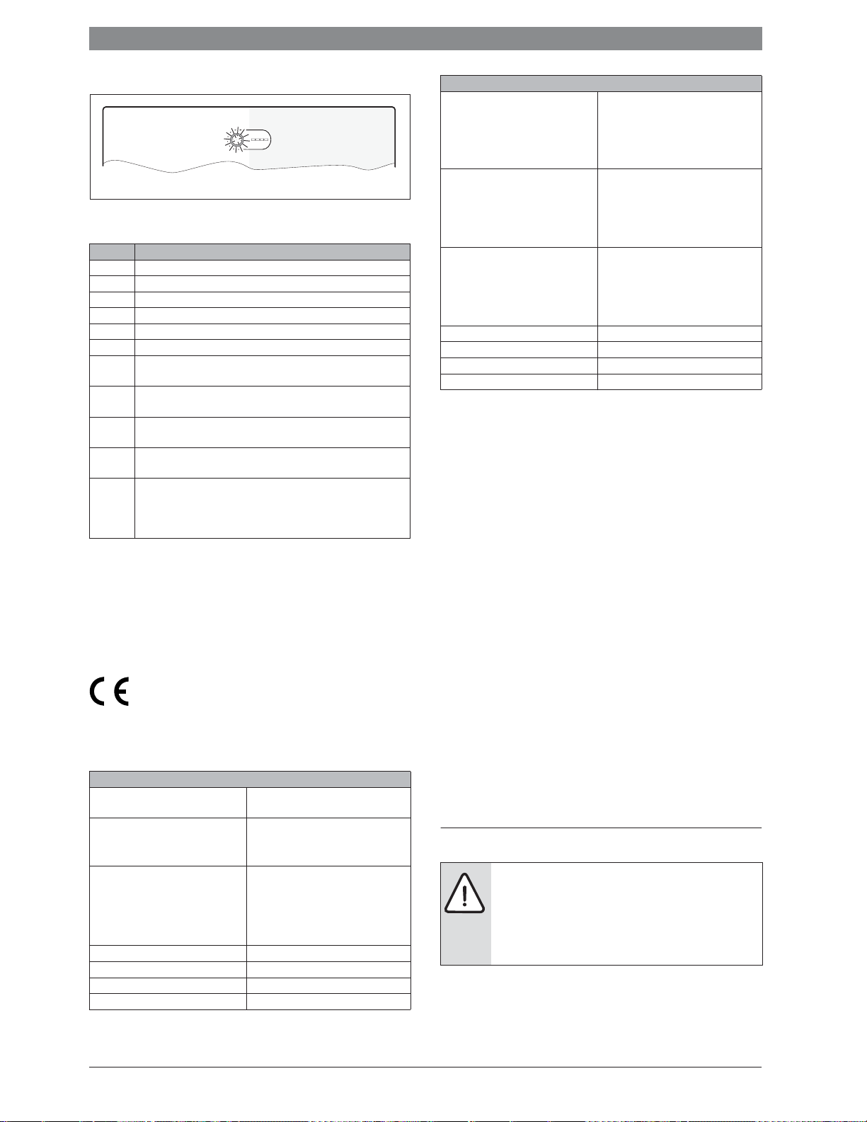
2.4 Kodierschalter einstellen
6 720 810 538-23.1O
Bild 3 Kodierschalter mit Zustandsanzeige des Moduls und Zustands-
anzeige der angeschlossenen Wärmeerzeuger oder Module
Kodierung Funktion des Moduls
0 Aus (Lieferzustand)
1 Serielle Standard-Kaskade
2 Serielle optimierte Kaskade (Æ Bild 24, Seite 89)
3 Serielle Kaskade mit Spitzenlastabdeckung
4 Parallele Kaskade
5 Keine Funktion
6 Externe 0-10 V-Leistungsregelung mit serieller Standard-Kaskade
(keine Interne Temperaturregelung)
7 Externe 0-10 V-Leistungsregelung mit serieller optimierter Kaska-
de (Æ Bild 25, Seite 90, keine Interne Temperaturregelung)
8 Externe 0-10 V-Vorlauftemperaturregelung mit serieller Standard-
Kaskade
9 Externe 0-10 V-Vorlauftemperaturregelung mit serieller optimier-
ter Kaskade
10 Das Modul ist eines von maximal 4 untergeordneten Kaskadenmo-
dulen. Das Übergeordnete Kaskadenmodul regelt die angeschlossenen Wärmeerzeuger entsprechend der daran eingestellten
Kodierung (Æ Bild 26, Seite 90).
Tab. 2 Kodierung und Funktion
2.5 Lieferumfang
Bild 5, Seite 86:
[1] Modul
[2] Beutel mit Zugentlastungen
[3] Installationsanleitung
2.6 Technische Daten
Dieses Produkt entspricht in Konstruktion und Betriebsverhalten den europäischen Richtlinien sowie den ergänzenden
nationalen Anforderungen. Die Konformität wurde mit der
CE-Kennzeichnung nachgewiesen. Sie können die Konformitätserklärung des Produkts anfordern. Wenden Sie sich dazu an die Adresse auf
der Rückseite dieser Anleitung.
Technische Daten
Abmessungen (B × H × T) 246 × 184 × 61 mm
(weitere Maße Æ Bild 6, Seite 86)
Maximaler Leiterquerschnitt
• Anschlussklemme 230 V
• Anschlussklemme Kleinspannung
Nennspannungen
• BUS
• Netzspannung Modul
• Bedieneinheit
• Pumpen u. Mischer
Sicherung 230 V, 5 AT
BUS-Schnittstelle EMS 2 / EMS plus
Leistungsaufnahme – Standby < 1,0 W
max. Leistungsabgabe 1100 W
• 2,5 mm
• 1,5 mm
• 15 V DC (verpolungssicher)
• 230 V AC, 50 Hz
• 15 V DC (verpolungssicher)
• 230 V AC, 50 Hz
Tab. 3
2
2
Technische Daten
Max. Leistungsabgabe pro Anschluss
• PC0, PC1
• A0, IA1
Messbereich Vorlauf- und Rücklauftemperaturfühler
• Untere Fehlergrenze
• Anzeigebereich
• Obere Fehlergrenze
Messbereich Außentemperaturfühler
• Untere Fehlergrenze
• Anzeigebereich
• Obere Fehlergrenze
Zul. Umgebungstemperatur 0 ... 60 °C
Schutzart IP44
Schutzklasse I
Ident.-Nr. Typschild (Æ Bild 23, Seite 89)
• 400 W (Hochefizienzpumpen
zulässig; max. 40 A/Ps)
• 10 W
• < – 10 °C
• 0 ... 100 °C
• > 125 °C
• < – 35 °C
• – 30 ... 50 °C
• > 125 °C
Tab. 3
2.7 Ergänzendes Zubehör
Genaue Angaben zu geeignetem Zubehör entnehmen Sie bitte dem
Katalog.
• Bedieneinheit: Außentemperaturgeführter Regler mit Außentemperaturfühler oder raumtemperaturgeführter Regler; Anschluss an BUS
(nicht an BUS1, BUS2, BUS3 oder BUS4 anschließen); Anschluss
Außentemperaturfühler an T1
• Vorlauftemperaturfühler; Anschluss an T0
• Außentemperaturfühler; Anschluss an T1
• Rücklauftemperaturfühler; Anschluss an T2
• Kaskadenpumpe; Anschluss an PC0
• Heizungspumpe; Anschluss an PC1
• Schalter für maximale Leistung; Anschluss an I2
• Stopp-Schalter; Anschluss an I3
• IGM für Wärmeerzeuger ohne EMS, EMS 2 oder EMS plus; Anschluss
gemäß technischer Dokumentation des IGM (das Kaskadenmodul
MC 400 ersetzt hierbei das ICM)
Installation des ergänzenden Zubehörs
▶ Ergänzendes Zubehör entsprechend den gesetzlichen Vorschriften
und der mitgelieferten Anleitungen installieren.
2.8 Reinigung
▶ Bei Bedarf mit einem feuchten Tuch das Gehäuse abreiben. Dabei
keine scharfen oder ätzenden Reinigungsmittel verwenden.
3 Installation
GEFAHR: Stromschlag!
▶ Vor Installation dieses Produktes: Wärmeerzeuger
und alle weiteren BUS-Teilnehmer allpolig von der
Netzspannung trennen.
▶ Vor Inbetriebnahme: Abdeckung anbringen
(Æ Bild 22, Seite 89).
3.1 Installation
▶ Modul an einer Wand (Æ Bild 7 bis Bild 9, ab Seite 86), an einer Hut-
schiene (Æ Bild 10, Seite 86) oder in einer Baugruppe installieren.
▶ Beim Entfernen des Moduls von der Hutschiene Bild 11 auf Seite 87
beachten.
6 720 819 669 (2016/05)MC 400

6 | Installation
3.2 Installation eines Temperaturfühlers an der hydraulischen Weiche
A
ϑ
1
1 2
T0
B
ϑ
3
ϑ
1
T0
ϑ
3
2
1
ϑ
2
Bild 4 Position Temperaturfühler Vorlauf (T0)
[1] Alle Wärmeerzeuger
[2] Alle Heizkreise
A Hydraulische Weiche Bauform 1
B Hydraulische Weiche Bauform 2
-
Gemeinsame Vorlauftemperatur aller Wärmeerzeuger
1
Gemeinsame Rücklauftemperatur aller Wärmeerzeuger
-
2
Gemeinsame Vorlauftemperatur aller Heizkreise
-
3
-
Gemeinsame Rücklauftemperatur aller Heizkreise
4
T
Temperaturfühler Vorlauf an der hydraulischen Weiche
0
T
ist so zu positionieren, dass -3 unabhängig vom Volumenstrom auf
0
der Seite aller Wärmeerzeuger [1] erfasst wird. Nur so kann die Regelung auch bei kleinen Lasten stabil arbeiten.
3.3 Elektrischer Anschluss
▶ Unter Berücksichtigung der geltenden Vorschriften für den An-
schluss mindestens Elektrokabel der Bauart H05 VV-... verwenden.
3.3.1 Anschluss BUS-Verbindung und Temperaturfühler
(Kleinspannungsseite)
BUS-Verbindung allgemein
Wenn die maximale Kabellänge der BUS-Verbindung zwischen allen BUS-Teilnehmern überschritten wird oder im
BUS-System eine Ringstruktur vorliegt, ist die Inbetriebnahme der Anlage nicht möglich.
ϑ
ϑ
4
2
ϑ
4
6 720 809 449-24.1O
Allgemeines zur Kleinspannungsseite
Bezeichnungen der Anschlussklemmen (Kleinspannungsseite d 24 V)
0-10 V Anschluss
2)
BUS
BUS1...4 Anschluss Wärmeerzeuger oder untergeordnete Kaskadenmodule
I2, I3 Anschluss exterer Schalter (Input)
OC1 Anschluss
T0, T1, T2 Anschluss Temperaturfühler (Temperature sensor)
1)
für 0-10 V-Raumtemperaturregler oder Gebäudeleittechnik mit einem 0-10 V-Reglerausgang zusätzlich LeistungsFeedback als 0-10 V Signal für Gebäudeleittechnik an Klemme 3
Anschluss an Regler, Module
3)
Drehzahlregelung Pumpe mit 0-10 V-Signal
(Output Cascade)
Tab. 4
1) Klemmenbelegung: 1 – Masse; 2 – 0-10 V-Eingang (Input) für Wärmeanforderung von der Gebäudeleittechnik; 3 – 0-10 V-Ausgang (Output, optional) für
Feedback
2) In einigen Geräten ist die Anschlussklemme für das BUS-System mit EMS
beschriftet.
3) Klemmenbelegung: 1 – Masse; 2 – Ausgang (Output); 3 – Eingang (Input, optional)
▶ Wenn PO zur Regelung verwendet wird, IA1 nicht brücken. Wenn IA1
gebrückt und PO offen ist, wird auf die eingestellte maximale Vorlauftemperatur geregelt.
▶ Um induktive Beeinflussungen zu vermeiden: Alle Kleinspannungs-
kabel von Netzspannung führenden Kabeln getrennt verlegen
(Mindestabstand 100 mm).
▶ Bei induktiven äußeren Einflüssen (z. B. von PV-Anlagen) Kabel ge-
schirmt ausführen (z. B. LiYCY) und Schirmung einseitig erden.
Schirmung nicht an Anschlussklemme für Schutzleiter im Modul anschließen, sondern an Hauserdung, z. B. freie Schutzleiterklemme
oder Wasserrohre.
▶ Kabel durch die bereits vormontierten Tüllen führen und gemäß den
Anschlussplänen anklemmen.
3.3.2 Anschluss Spannungsversorgung, Pumpe und Mischer
(Netzspannungsseite)
Bezeichnungen der Anschlussklemmen (Netzspannungsseite)
120/230 V AC Anschluss Netzspannung
PC0, PC1 Anschluss Pumpe (Pump Cascade)
A0 Anschluss für Störungsmeldung (Alert)
IA1 Anschluss für on/off-Regler 230 V)
Tab. 5
Maximale Gesamtlänge der BUS-Verbindungen:
• 100 m mit 0,50 mm
• 300 m mit 1,50 mm
2
Leiterquerschnitt
2
Leiterquerschnitt
BUS-Verbindung Wärmeerzeuger – Kaskadenmodule
▶ Wärmeerzeuger und untergeordnete Kaskadenmodule direkt an den
Anschlussklemmen BUS1 ... BUS4 anschließen (Æ Überblick der
Anschlussklemmenbelegung).
BUS-Verbindung Kaskadenmodul – Bedieneinheit – andere Module
▶ Bei unterschiedlichen Leiterquerschnitten Verteilerdose für den An-
schluss der BUS-Teilnehmer verwenden.
▶ BUS-Teilnehmer [B] über Verteilerdose [A] in Stern (Æ Bild 20,
Seite 88, Anleitung der Bedieneinheit und der anderen Module beachten).
Temperaturfühler
Bei Verlängerung der Fühlerleitung folgende Leiterquerschnitte verwenden:
• Bis 20 m mit 0,75 mm
• 20 m bis 100 m mit 1,50 mm
2
bis 1,50 mm2 Leiterquerschnitt
2
Leiterquerschnitt
Die Belegung der elektrischen Anschlüsse ist von der installierten Anlage abhängig. Die in Bild 13 bis 20, ab Seite 87
dargestellte Beschreibung ist ein Vorschlag für den Ablauf
des elektrischen Anschlusses. Die Handlungsschritte sind
teilweise in unterschiedlichen Farben dargestellt. Damit ist
leichter zu erkennen, welche Handlungsschritte zusammengehören.
▶ Nur Elektrokabel gleicher Qualität verwenden.
▶ Auf phasenrichtige Installation des Netzanschlusses achten.
Netzanschluss über einen Schutzkontaktstecker ist nicht zulässig.
▶ An den Ausgängen nur Bauteile und Baugruppen gemäß dieser Anlei-
tung anschließen. Keine zusätzlichen Steuerungen anschließen, die
weitere Anlagenteile steuern.
MC 4006 720 819 669 (2016/05)
Installation | 7
0
1
2
3
4
5
6
7
8
9
10
Die maximale Leistungsaufnahme der angeschlossenen
Bauteile und Baugruppen darf die in den technischen Daten
des Moduls angegebene Leistungsabgabe nicht überschreiten.
▶ Wenn die Netzspannungsversorgung nicht über die Elek-
tronik des Wärmeerzeugers erfolgt: bauseits zur Unterbrechung der Netzspannungsversorgung eine allpolige
normgerechte Trennvorrichtung (nach EN 60335-1) installieren.
▶ Kabel durch die Tüllen führen, gemäß den Anschlussplänen anklem-
men und mit den im Lieferumfang enthaltenen Zugentlastungen sichern (Æ Bild 12 bis 19, ab Seite 87).
3.3.3 Anschlusspläne mit Anlagenbeispielen
Die hydraulischen Darstellungen sind nur schematisch und geben einen
unverbindlichen Hinweis auf eine mögliche hydraulische Schaltung. Die
Sicherheitseinrichtungen sind nach den gültigen Normen und örtlichen
MC400
10
120/230 V AC
A0
PC0
N63
CNO NC
T0 I2 I3
Vorschriften auszuführen. Weitere Informationen und Möglichkeiten
entnehmen Sie bitte den Planungsunterlagen oder der Ausschreibung.
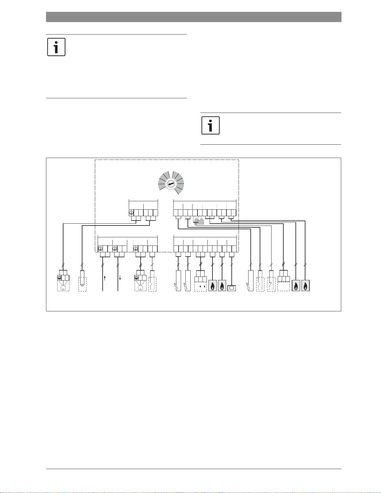
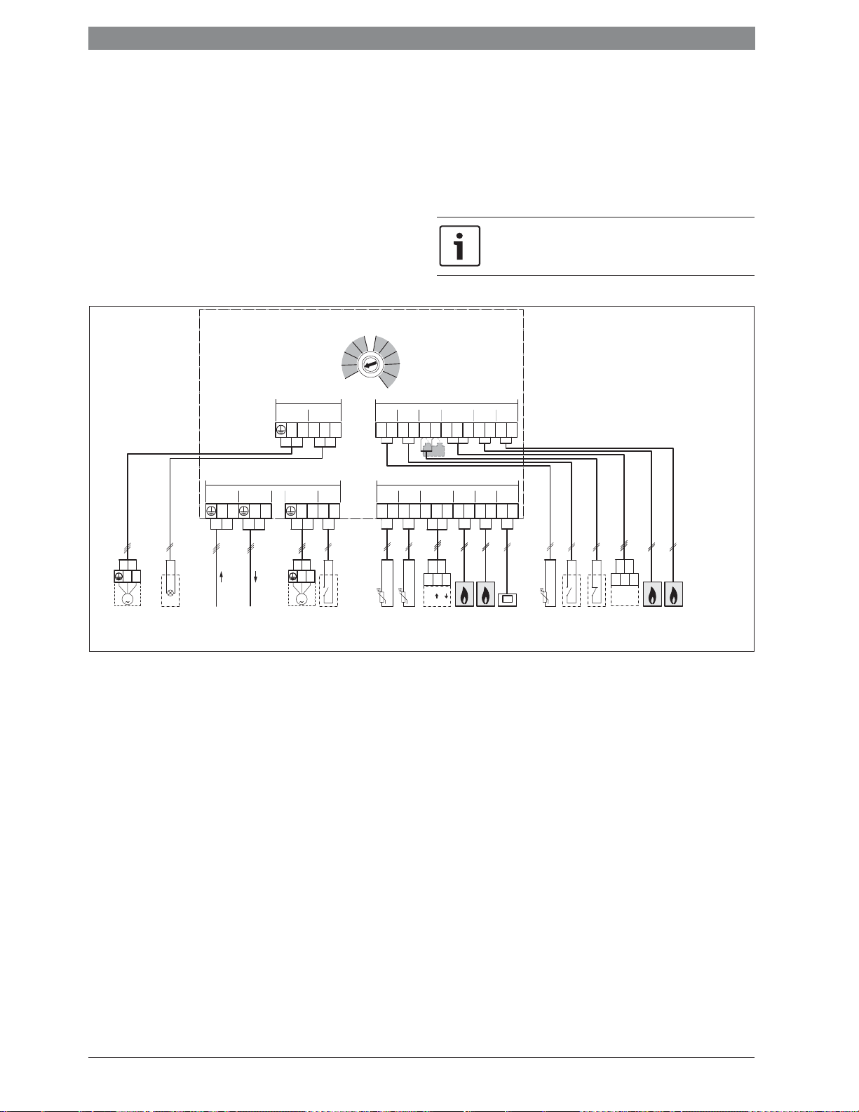
3.3.4 Überblick Anschlussklemmenbelegung
Dieser Überblick zeigt für alle Anschlussklemmen des Moduls, welche
Anlagenteile angeschlossen werden können. Die mit * gekennzeichneten
Bauteile (z. B. HS1 und M1) der Anlage sind alternativ möglich. Je nach
Verwendung des Moduls wird eines der Bauteile an der Anschlussklemme „BUS1“ angeschlossen.
Komplexere Anlagen werden in Kombination mit weiteren Kaskadenmodulen realisiert. Dabei sind vom Überblick der Anschlussklemmen abweichende Belegungen der Anschlussklemmen möglich.
Wenn an Anschlussklemme I3 kein Stopp-Schalter (Öffner)
angeschlossen ist:
▶ Im Lieferumfang enthaltene Brücke an Anschluss-
klemme I3 anschließen.
1)
≤ 24V
BUS3 BUS4
OC1
123
1212121212
1)
≤ 24V
T2 BUS1
0-10V
123
12 12
123
(-) (+) (+)
PO
HS1*
M1*
BUS2
12
HS5*
M2*
BUS
CONT2IA1A0
PC0
NL
M
120/230 V AC
120/230VAC 120/230VAC
NL N LINN63L
PC1 IA1
NL
M
PC1
T1
1212
T1 T0
Legende zum Bild oben und zu Bild 24 bis 26 (keine Bezeichnung der Anschlussklemmen):
230 V AC Anschluss Netzspannung
A0 Fernstöranzeige 230 V bauseitig
BUS BUS-System EMS 2 / EMS plus (nicht an BUS1 ... BUS4
anschließen)
BUS1...4 BUS-System EMS / EMS plus oder EMS 2 / 2-Draht-BUS
(direkt an HS1 ... HS4 oder M1 ... M4 anschließen)
CON Bedieneinheit mit BUS-System EMS 2 / EMS plus (Controler)
GLT Gebäudeleittechnik mit 0-10V Schnittstellen (GebäudeLeit-
Technik)
HS1, HS5, HS9, HS13
Wärmeerzeuger 1 (HS1 an BUS1), 2 (HS5 an BUS2),
3 (HS9 an BUS3) und 4 (HS13 an BUS4) an einzigem
MC 400 / (Heat Source)
HS1...4 Wärmeerzeuger 1 (an BUS1) ... 4 (an BUS4) an erstem unter-
geordnetem MC 400 (M1) / (Heat Source)
HS5...8 Wärmeerzeuger 1 (an BUS1) ... 4 (an BUS4) an zweitem un-
tergeordnetem MC 400 (M2) / (Heat Source)
I2 Schalter für maximale Leistung (alle Geräte gehen auf maxi-
male Leistung, wenn geschlossen; Input)
I3 Stopp-Schalter (Wärmeanforderung aller Geräte wird unter-
brochen, wenn geöffnet; Input)
M1...4 untergeordnetes Kaskadenmodul 1 (an BUS1) ...
4 (an BUS4)
MC 400 Kaskadenmodul
MM 100 Heizkreismodul (EMS 2 / EMS plus)
PC0 Kaskadenpumpe (Ein-/Aus oder optional Drehzahlregelung
über 0-10V-Signal mit an Anschluss OC1; Pump Cascade);
nur bei Wärmeerzeugern ohne Pumpe
PC1 Heizungspumpe (Pump Circuit); nur bei einem ungemischten
Heizkreis ohne MM 100 (Zubringerpumpe oder Heizungs-
pumpe)
PO Eingang und Feedback für Leistungsregelung über ein
0-10 V-Signal (Power In-/Output); Klemmenbelegung:
1 – 2 Eingang; 1 – 3 Ausgang)
T0 Temperaturfühler Vorlauf (Temperature sensor)
T1 Temperaturfühler Außentemperatur (Temperature sensor)
T2 Temperaturfühler Rücklauf (nur erforderlich, wenn PC0 mit
Drehzahlregelung über 0-10 V-Signal an Anschluss OC1;
sonst optional; Temperature sensor)
1) Nur erforderlich, wenn an Anschlussklemme I3 kein Stopp-
Schalter angeschlossen ist.
IA1 Eingang on/off-Regler 230 V (Kodierung 6 ... 9)
123
0-10V
PC0
HS9*
I2 I3230 V AC230 V AC
M3*
HS13*
M4*
6 720 809 449-16.4O
6 720 819 669 (2016/05)MC 400
8 | Inbetriebnahme
4 Inbetriebnahme
HINWEIS: Anlagenschaden durch zerstörte Pumpe!
▶ Vor dem Einschalten die Anlage befüllen und entlüften,
damit die Pumpen nicht trocken laufen.
Alle elektrischen Anschlüsse richtig anschließen und erst
danach die Inbetriebnahme durchführen!
▶ Installationsanleitungen aller Bauteile und Baugruppen
der Anlage beachten.
▶ Spannungsversorgung nur einschalten, wenn alle
Module eingestellt sind.
4.1 Kodierschalter einstellen
Wenn der Kodierschalter auf einer gültigen Position steht und die Kommunikation über das BUS-System aufgebaut ist, leuchtet die Betriebsanzeige dauerhaft grün. Wenn der Kodierschalter auf einer ungültigen
Position oder in Zwischenstellung steht, leuchtet die Betriebsanzeige
zunächst nicht und anschließend rot.
Wenn am übergeordneten Modul MC 400 der Kodierschalter auf 10 eingestellt ist und eine direkte BUS-Verbindung
zwischen einem Wärmeerzeuger und diesem Modul besteht, ist die Inbetriebnahme der Anlage nicht möglich.
4.2 Inbetriebnahme der Anlage und des Moduls
HINWEIS: Anlagenschaden durch zerstörte Pumpe!
▶ Vor dem Einschalten die Anlage befüllen und entlüften,
damit die Pumpen nicht trocken laufen.
Wenn ein IGM installiert ist, müssen folgende Punkte beachtet werden:
▶ Am IGM die maximale und minimale Leistung des ange-
schlossenen Gerätes einstellen.
▶ Maximale Leistung mindestens auf 5 kW einstellen, da
sonst das IGM nicht von der Kaskadenregelung verwendet wird.
▶ Wenn das angeschlossene Gerät ein Zweipunkt-Gerät
ist, maximale Leistung = minimale Leistung einstellen.
1. Netzspannung (allpolig) spannungsfrei schalten und gegen Wiedereinschalten sichern.
2. Spannungsfreiheit feststellen.
3. Alle benötigten Fühler und Aktoren anschließen.
4. Spannungsversorgung (230 V AC) mechanisch an allen installierten
Modulen und Wärmeerzeugern herstellen.
4.2.1 Einstellungen bei Anlagen mit einem Kaskadenmodul im
BUS-System
1. Regelungsstrategie mit dem Kodierschalter am Kaskadenmodul einstellen.
2. Kodierschalter ggf. an weiteren Modulen einstellen.
3. Spannungsversorgung (Netzspannung) der gesamten Anlage einschalten.
Das Modul MC 400 detektiert die angeschlossenen Wärmeerzeuger.
Abhängig von der Anzahl kann dies bis zu 5 Minuten dauern. In dieser
Zeit erfolgt keine Reaktion auf Heizbefehle der Bedieneinheit. Sobald
der erste Wärmeerzeuger erkannt wurde, aktiviert das MC 400 die
Versorgungsspannung der Bedieneinheit mit BUS-System EMS 2 /
EMS plus (CON)
Wenn die Betriebsanzeige des Moduls dauernd grün leuchtet:
4. Bedieneinheit gemäß beiliegender Installationsanleitung in Betrieb
nehmen und entsprechend einstellen.
5. Raumeinfluss an der Bedieneinheit auf 0 stellen.
6. Einstellungen an der Bedieneinheit für die Kaskade prüfen und ggf.
auf die installierte Anlage abstimmen.
4.2.2 Einstellungen bei Anlagen mit 2 oder mehr Kaskadenmodu-
len im BUS-System
In einer Anlage können bis zu 16 Wärmeerzeuger installiert werden. In
solchen Fällen gibt es ein übergeordnetes Kaskadenmodul und 1 bis 4
untergeordnete Kaskadenmodule.
1. Regelungsstrategie mit dem Kodierschalter am übergeordneten
Kaskadenmodul einstellen.
2. Kodierschalter an den untergeordneten Kaskadenmodulen auf 10
einstellen.
3. Kodierschalter ggf. an weiteren Modulen einstellen.
4. Spannungsversorgung der Wärmeerzeuger einschalten.
5. Spannungsversorgung für Module einschalten.
Die MC 400 detektieren die angeschlossenen Wärmeerzeuger und
ggf. weitere MC 400 (untergeordnete Module). Abhängig von der Anzahl kann dies bis zu 5 Minuten dauern. In dieser Zeit erfolgt keine
Reaktion auf Heizbefehle der Bedieneinheit. Sobald der erste Wärmeerzeuger erkannt wurde, aktiviert das MC 400 die Versorgungsspannung der Bedieneinheit mit BUS-System EMS 2 / EMS plus
(CON).
6. Bedieneinheit gemäß beiliegender Installationsanleitung in Betrieb
nehmen und entsprechend einstellen.
7. Raumeinfluss an der Bedieneinheit auf 0 stellen.
8. Einstellungen an der Bedieneinheit für die Kaskade prüfen und ggf.
auf die installierte Anlage abstimmen.
4.3 Zustandsanzeige für Wärmeerzeuger/untergeordne-
te Kaskadenmodule am übergeordneten Kaskadenmodul
Neben dem Kodierschalter sind am Modul 4 LEDs, die den jeweiligen
Zustand der angeschlossenen Wärmeerzeuger/Module anzeigen.
• LED 1, 2, 3 und 4 zeigen den Zustand der entsprechend am Modul
angeschlossenen Wärmeerzeuger/untergeordneten Kaskadenmodule:
– aus: Verbindung getrennt oder keine Kommunikation
– rot: Wärmeerzeuger gefunden, aber Verbindung unterbrochen
oder Störung am Wärmeerzeuger
– gelb: Wärmeerzeuger angeschlossen, keine Wärmeanforderung
– blinkt gelb: Wärmeerzeuger gefunden, Wärmeanforderung liegt
vor, aber der Brenner ist aus
– grün: untergeordnetes Modul gefunden -oder- Wärmeerzeuger
gefunden, Wärmeanforderung liegt vor, Brenner in Betrieb, Hei-
zung aktiv
– blinkt grün: untergeordnetes Modul gefunden -oder- Wärmeer-
zeuger gefunden, Wärmeanforderung liegt vor, Brenner in Be-
trieb, Warmwasserbereitung aktiv
4.4 Zustandsanzeige der Wärmeerzeuger am untergeordneten Kaskadenmodul
Neben dem Kodierschalter sind am Modul 4 LEDs, die den jeweiligen
Zustand der angeschlossenen Wärmeerzeuger/Module anzeigen.
• LED 1, 2, 3 und 4 zeigen den Zustand der entsprechenden Wärmeer-
zeuger:
– aus: Verbindung getrennt oder keine Kommunikation
– rot: Kaskadenmodul gefunden -oder- Wärmeerzeuger gefunden,
aber Verbindung unterbrochen oder Störung am Wärmeerzeuger
– gelb: Wärmeerzeuger angeschlossen, keine Wärmeanforderung
MC 4006 720 819 669 (2016/05)
Inbetriebnahme | 9
– blinkt gelb: Wärmeerzeuger gefunden, Wärmeanforderung liegt
vor, aber der Brenner ist aus (z. B., wenn die Taktsperre des Wärmeerzeugers aktiv ist)
– grün: Wärmeerzeuger gefunden, Wärmeanforderung liegt vor,
Brenner in Betrieb, Heizung aktiv
– blinkt grün: Wärmeerzeuger gefunden, Wärmeanforderung liegt
vor, Brenner in Betrieb, Warmwasserbereitung aktiv
4.5 Menü Einstellungen Kaskade
Wenn ein Kaskadenmodul installiert ist, wird an der Bedieneinheit das
Menü Servicemenü > Einstellungen Kaskade angezeigt (nicht bei allen Bedieneinheiten verfügbar). Wenn dieses Menü bei der installierten
Bedieneinheit nicht verfügbar ist, verwendet das Kaskadenmodul die
Grundeinstellungen. Die Einstellungen können mit einer geeigneten Bedieneinheit geändert werden, auch wenn die Bedieneinheit nur vorübergehend angeschlossen ist.
Die Grundeinstellungen sind in den Einstellbereichen
hervorgehoben.
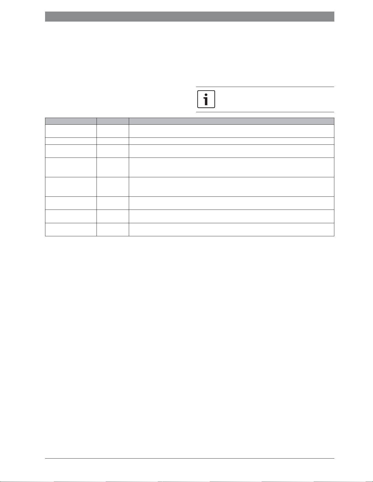
Menüpunkt Einstellbereich Funktionsbeschreibung
Offset Weichensensor – 20 ... 0
... 20 K
Solltemp. Kaskade Max 30 ... 90 °C Maximale Vorlauftemperatur der Kaskade an der hydraulischen Weiche.
Nachlaufzeit Kask.pumpe 0 ... 3 ... 15 min Die am Kaskadenmodul angeschlossene Heizungspumpe (Sekundärseite) läuft für die hier eingestellte Dauer länger,
Vorlauftemp. Spitzenlast 30 ... 50
... 70 °C
Außentemp. Spitzenlast – 20 ... 10
... 20 °C
Anlaufverzög. Folgegerät 0 ... 6 ... 30 min Wenn ein Wärmeerzeuger zugeschaltet wurde, wartet die Regelung für die hier eingestellte Dauer, bis das nächste
Tolerierte Übertemperatur 0 ... 5 ... 10 K Zur Verringerung des Gerätetaktens werden Wärmeerzeuger erst abgeschaltet, wenn die Vorlauftemperatur die
Tolerierte Untertemperatur 0 ... 5 ... 10 K Zur Verringerung des Gerätetaktens werden Wärmeerzeuger erst zugeschaltet, wenn die Vorlauftemperatur die
Die von der Regelung angeforderte Vorlauftemperatur wird um diesen Wert geändert.
als es eine Wärmeanforderung gibt.
Wenn die von der Regelung angeforderte Vorlauftemperatur den hier eingestellten Wert überschreitet, werden bei der
Regelungsstrategie Serielle Kaskade mit Spitzenlastabdeckung (Kodierschalter auf Position 3) die zur Spitzenlastabdeckung erforderlichen Wärmeerzeuger zugeschaltet.
Wenn die Außentemperatur den hier eingestellten Wert unterschreitet, werden bei der Regelungsstrategie Serielle
Kaskade mit Spitzenlastabdeckung (Kodierschalter auf Position 3) die zur Spitzenlastabdeckung erforderlichen Wärmeerzeuger zugeschaltet.
Gerät zugeschaltet wird.
gewünschte Solltemperatur um die tolerierte Übertemperatur überschreitet (positive Schaltdifferenz).
gewünschte Solltemperatur um die tolerierte Untertemperatur unterschreitet (negative Schaltdifferenz).
Tab. 6
4.6 Menü Diagnose
Die Menüs sind von der installierten Bedieneinheit und der installierten
Anlage abhängig.
Monitorwerte
Wenn ein Modul MC 400 installiert ist, wird das Menü Monitorwerte >
Kaskade angezeigt.
In diesem Menü können Informationen zum aktuellen Zustand der Anlage und der einzelnen Geräte in der Kaskade abgerufen werden. Z. B.
kann hier angezeigt werden, wie hoch die Vor- und Rücklauftemperatur
der Anlage oder die aktuell erbrachte Geräteleistung ist.
Wenn ein Modul MC 400 installiert ist, wird das Menü Monitorwerte >
Systeminformationen > Kaskade angezeigt.
In diesem Menü können Informationen über das Modul MC 400 (Typ
Kaskadenmodul, SW-Vers. Kaskadenmodul) und die einzelnen Geräte in der Kaskade (z. B. Typ Steuereinheit 1, SW-Vers. Steuereinheit
1) abgerufen werden.
Verfügbare Informationen und Werte sind dabei abhängig von der instal-
lierten Anlage. Technische Dokumente des Wärmeerzeugers, der Bedieneinheit, der weiteren Module und anderer Anlagenteile beachten.
6 720 819 669 (2016/05)MC 400
10 | Störungen beheben
0
1
2
3
4
5
6
7
8
9
10
5 Störungen beheben
Nur Originalersatzteile verwenden. Schäden, die durch
nicht vom Hersteller gelieferte Ersatzteile entstehen, sind
von der Haftung ausgeschlossen.
Wenn sich eine Störung nicht beheben lässt, bitte an den zuständigen Servicetechniker wenden.
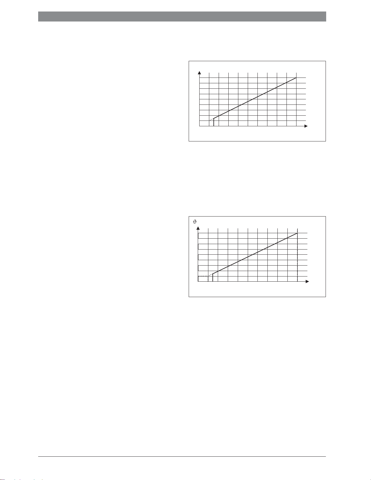
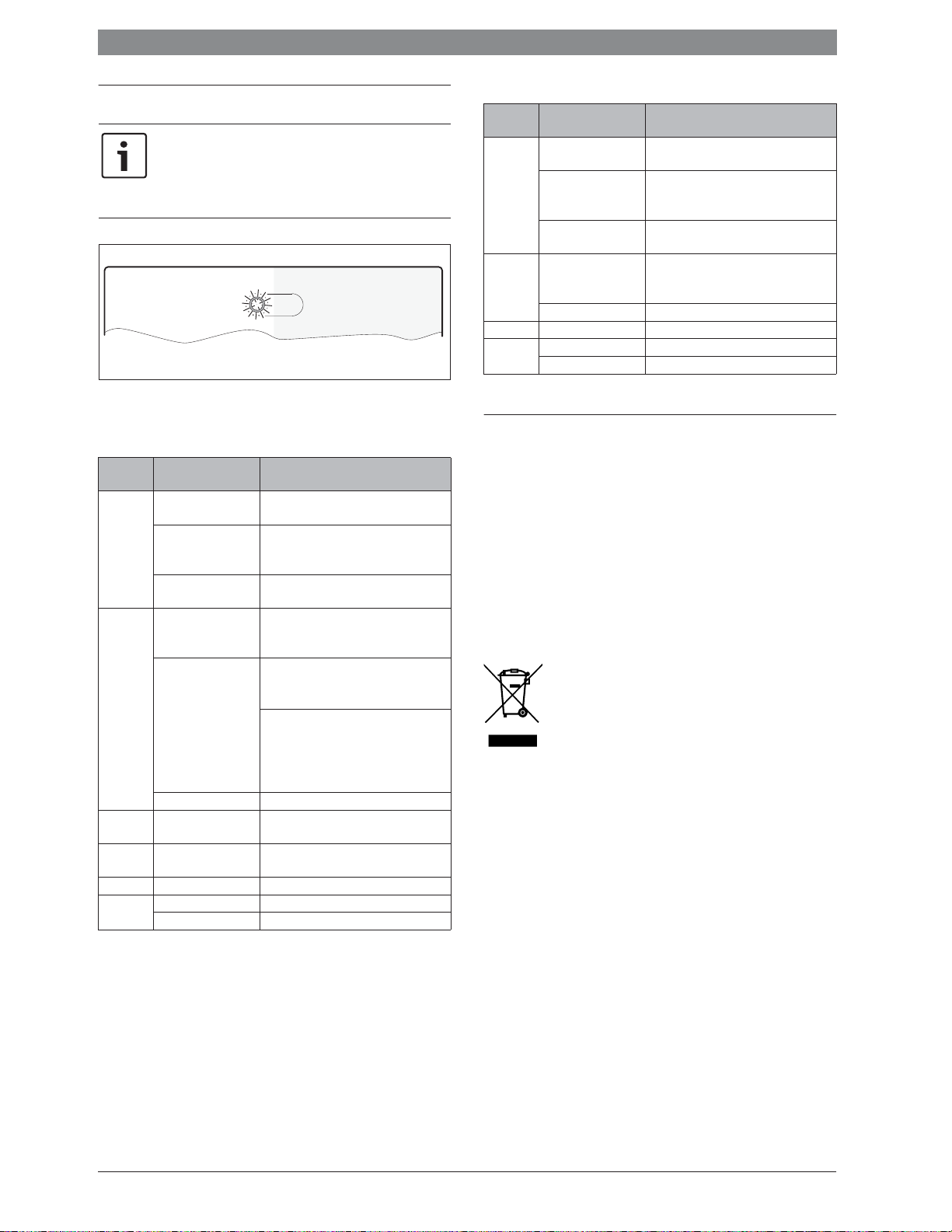
Die Betriebsanzeige zeigt den Betriebszustand des Moduls.
6 720 647 922-52.1O
5.2
Betriebsanzeige an untergeordnetem Kaskadenmodul
Betriebsanzeige
dauernd
aus
Mögliche Ursache Abhilfe
Spannungsversorgung
▶ Spannungsversorgung einschalten.
unterbrochen.
Sicherung defekt. ▶ Bei ausgeschalteter Spannungsver-
sorgung Sicherung tauschen
(Æ Bild 21 auf Seite 89)
dauernd
rot
Kurzschluss in BUSVerbindung.
Kodierschalter auf ungültiger Position oder
▶ BUS-Verbindung prüfen und ggf.
instandsetzen.
▶ Kodierschalter einstellen.
in Zwischenstellung.
Interne Störung ▶ Modul austauschen.
blinkt gelb Initialisierung –
dauernd
grün
Kodierschalter auf 0. ▶ Kodierschalter einstellen.
Keine Störung Normalbetrieb
Tab. 8
5.1 Betriebsanzeige an einzeln installiertem oder übergeordnetem Kaskadenmodul
Betriebsanzeige
dauernd
aus
dauernd
rot
blinkt rot Stopp-Schalter an I3
blinkt grün Schalter für max. Leis-
blinkt gelb Initialisierung –
dauernd
grün
Tab. 7
Mögliche Ursache Abhilfe
Spannungsversorgung
▶ Spannungsversorgung einschalten.
unterbrochen
Sicherung defekt ▶ Bei ausgeschalteter Spannungsver-
sorgung Sicherung tauschen
(Æ Bild 21 auf Seite 89)
Kurzschluss in BUSVerbindung
Kodierschalter auf un-
▶ BUS-Verbindung prüfen und ggf.
instandsetzen.
▶ Kodierschalter einstellen.
gültiger Position oder
in Zwischenstellung.
Temperaturfühler
defekt
▶
Temperaturfühler prüfen.
▶ Wenn Werte nicht übereinstimmen,
dann den Fühler austauschen
▶
Spannung an den Anschlussklemmen
des Temperaturfühlers im Modul prüfen
▶ Wenn die Fühlerwerte stimmen, aber
die Spannungswerte nicht übereinstimmen, Modul austauschen
Interne Störung ▶ Modul austauschen.
▶ Stopp-Schalter prüfen.
ist offen
Max-Schalter an I2 prüfen
tung ist geschlossen
Kodierschalter auf 0 ▶ Kodierschalter einstellen.
Keine Störung Normalbetrieb
6 Umweltschutz/Entsorgung
Umweltschutz ist ein Unternehmensgrundsatz der Bosch Gruppe.
Qualität der Produkte, Wirtschaftlichkeit und Umweltschutz sind für uns
gleichrangige Ziele. Gesetze und Vorschriften zum Umweltschutz werden strikt eingehalten.
Zum Schutz der Umwelt setzen wir unter Berücksichtigung wirtschaftlicher Gesichtspunkte bestmögliche Technik und Materialien ein.
Verpackung
Bei der Verpackung sind wir an den länderspezifischen Verwertungssystemen beteiligt, die ein optimales Recycling gewährleisten.
Alle verwendeten Verpackungsmaterialien sind umweltverträglich und
wiederverwertbar.
Elektro- und Elektronik-Altgeräte
Nicht mehr gebrauchsfähige Elektro- oder Elektronikgeräte müssen getrennt gesammelt und einer umweltgerechten Verwertung zugeführt werden (Europäische Richtlinie
über Elektro- und Elektronik-Altgeräte).
.
Nutzen Sie zur Entsorgung von Elektro- oder ElektronikAltgeräten die länderspezifischen Rückgabe- und Sammelsysteme.
MC 4006 720 819 669 (2016/05)
Contents | 11
Contents
1 Key to symbols and safety instructions . . . . . . . . . . . . . . . . . 11
1.1 Key to symbols . . . . . . . . . . . . . . . . . . . . . . . . . . . . . . . . 11
1.2 General safety instructions . . . . . . . . . . . . . . . . . . . . . . 11
2 Product details . . . . . . . . . . . . . . . . . . . . . . . . . . . . . . . . . . . . . . 12
2.1 Important usage information . . . . . . . . . . . . . . . . . . . . 12
2.2 Function description . . . . . . . . . . . . . . . . . . . . . . . . . . . 12
2.2.1 Basic principle . . . . . . . . . . . . . . . . . . . . . . . . . . . . . . . . 12
2.2.2 Time limits . . . . . . . . . . . . . . . . . . . . . . . . . . . . . . . . . . . 12
2.3 Control strategies . . . . . . . . . . . . . . . . . . . . . . . . . . . . . 13
2.3.1 Serial standard cascade . . . . . . . . . . . . . . . . . . . . . . . . 13
2.3.2 Serial optimised cascade . . . . . . . . . . . . . . . . . . . . . . . 13
2.3.3 Serial cascade with peak load coverage . . . . . . . . . . . . 13
2.3.4 Parallel cascade . . . . . . . . . . . . . . . . . . . . . . . . . . . . . . . 13
2.3.5 Output control . . . . . . . . . . . . . . . . . . . . . . . . . . . . . . . . 13
2.3.6 Flow temperature control . . . . . . . . . . . . . . . . . . . . . . . 13
2.3.7 Pump pre-run . . . . . . . . . . . . . . . . . . . . . . . . . . . . . . . . . 13
2.4 Setting the coding card . . . . . . . . . . . . . . . . . . . . . . . . . 14
2.5 Scope of delivery . . . . . . . . . . . . . . . . . . . . . . . . . . . . . . 14
2.6 Specifications . . . . . . . . . . . . . . . . . . . . . . . . . . . . . . . . 14
2.7 Additional accessories . . . . . . . . . . . . . . . . . . . . . . . . . 14
2.8 Cleaning . . . . . . . . . . . . . . . . . . . . . . . . . . . . . . . . . . . . . 14
3 Mounting . . . . . . . . . . . . . . . . . . . . . . . . . . . . . . . . . . . . . . . . . . . 14
3.1 Installation . . . . . . . . . . . . . . . . . . . . . . . . . . . . . . . . . . . 14
3.2 Installation of temperature sensor on the low loss
header . . . . . . . . . . . . . . . . . . . . . . . . . . . . . . . . . . . . . . .15
3.3 Electrical connection . . . . . . . . . . . . . . . . . . . . . . . . . . . 15
3.3.1 Connecting the BUS connection and temperature
sensor (extra-low voltage side) . . . . . . . . . . . . . . . . . . .15
3.3.2 Connecting the power supply, pump and mixer
(mains voltage side) . . . . . . . . . . . . . . . . . . . . . . . . . . . .15
3.3.3 Connection diagrams with system schematics . . . . . . 16
3.3.4 Overview of the terminal assignment . . . . . . . . . . . . . . 16
4 Commissioning . . . . . . . . . . . . . . . . . . . . . . . . . . . . . . . . . . . . . . 17
4.1 Setting the coding card . . . . . . . . . . . . . . . . . . . . . . . . . 17
4.2 System and module commissioning . . . . . . . . . . . . . . . 17
4.2.1 Settings for systems with a cascade module in
the BUS system . . . . . . . . . . . . . . . . . . . . . . . . . . . . . . . .17
4.2.2 Settings for systems with 2 or more cascade
modules in the BUS system . . . . . . . . . . . . . . . . . . . . . .17
4.3 Status display for the heat source/subordinate
cascade modules on the subordinate cascade modul
4.4 Status display for the heat source on the
subordinate cascade module . . . . . . . . . . . . . . . . . . . . .17
4.5 Cascade settings menu . . . . . . . . . . . . . . . . . . . . . . . . . 18
4.6 Diagnosis menu . . . . . . . . . . . . . . . . . . . . . . . . . . . . . . . 18
5 Eliminate fault . . . . . . . . . . . . . . . . . . . . . . . . . . . . . . . . . . . . . . 19
5.1 Status indicator on the individual installed or
higher-level cascade module . . . . . . . . . . . . . . . . . . . . .19
5.2 Status indicator on the lower-level cascade module . . 19
e . .17
1 Key to symbols and safety instructions
1.1 Key to symbols
Warnings
Warnings in this document are identified by a warning
triangle printed against a grey background.
Keywords at the start of a warning indicate the type and
seriousness of the ensuing risk if measures to prevent
the risk are not taken.
The following keywords are defined and can be used in this document:
• NOTICE indicates a situation that could result in damage to property
or equipment.
• CAUTION indicates a situation that could result in minor to medium
injury.
• WARNING indicates a situation that could result in severe injury or
death.
• DANGER indicates a situation that will result in severe injury or
death.
Important information
This symbol indicates important information where
there is no risk to people or property.
Additional symbols
Symbol Explanation
▶ Step in an action sequence
Æ Cross-reference to another part of the document
• List entry
– List entry (second level)
Table 1
1.2 General safety instructions
These installation instructions are intended for a competent person.
▶ Read the installation instructions (heat appliances, modules, etc.)
before installation.
▶ Observe safety instructions and warnings.
▶ Observe national and regional regulations, technical rules and
guidelines.
▶ Keep a record of any work carried out.
Determined use
▶ Use the product only to control heating systems with cascade
systems. In a cascade system, several heat sources are used to
achieve greater heat output.
Any other use is considered inappropriate. Any damage that may result
is excluded from liability.
Installation, commissioning and maintenance
Installation, commissioning and maintenance must only be carried out
by a competent person.
▶ Never install the product in wet rooms.
▶ Only install genuine spare parts.
6 Environment / disposal . . . . . . . . . . . . . . . . . . . . . . . . . . . . . . . 19
6 720 819 669 (2016/05)MC 400

12 | Product details
Electrical work
Electrical work must only be carried out by qualified and competent
persons.
▶ Before carrying out electrical work:
– Isolate all poles of the mains voltage and secure against
unintentional reconnection.
– Using suitable means, test that the power supply is isolated.
▶ The product requires different voltages.
Do not connect the extra-low voltage side to the mains voltage or vice
versa.
▶ Also observe connection diagrams of other system components.
Handover to the end user
When handing over the heating system, explain the operating conditions
to the end user.
▶ Explain how to operate the heating system, with particular emphasis
on all safety-related actions.
▶ Explain that conversions or maintenance must only be carried out by
a suitably qualified engineer.
▶ Highlight the need for regular inspections and maintenance for safe
and environmentally friendly operation.
▶ The installation and operating instructions must be given to the end
user for safekeeping.
Damage caused by frost
The system can freeze if it is switched off:
▶ Observe the notices regarding frost protection.
▶ Due to the additional functions, e.g. DHW heating or anti-seizing
protection, the system should always be left on.
▶ Correct any faults immediately.
2 Product details
The module is designed to control cascade systems. A cascade system is
a heating system in which several heat sources are used to obtain greater
heat output. See example wiring diagram on page 90.
• The module is used to activate the heat source (e.g. boiler).
• The module is used to record external, flow and return temperature.
• Configuration of the cascade system with a user interface (e.g.
heating control) with an EMS 2/EMS plus BUS interface (not possible
with all user interfaces).
The combination options for the modules are shown in the connection
diagrams.
2.1 Important usage information
The module communicates via an EMS 2 / EMS plus interface with other
EMS 2 / EMS plus-enabled BUS modules (e.g. MM100).
If the pump speed is too low when the burner is started in
heat sources with a variable speed pump, high
temperatures and frequent burner cycles can arise.
▶ If possible, configure the pump to On/Off mode with
100 % output, otherwise set minimum pump output to
the highest possible value.
• The module can be connected to user interfaces with an EMS 2 / EMS
plus (Energy Management System) BUS interface. Alternatively, an
external output demand or temperature demand can be connected
via the 0-10 V interface on the module.
• The module only communicates with heat sources with EMS, EMS 2,
EMS plus and 2-wire BUS (HTIII) (with the exception of heat sources
of product series GB112,GB132, GB135, GB142, GB152).
• Only connect heat sources from a single manufacturer.
• Only use with cascade installations containing natural gas, LPG or oilfired heat sources (heat pumps with an EMS 2 / EMS plus BUS
interface are not allowed).
• The installation location must be suitable for the IP rating stated in
the module specifications.
• If a DHW cylinder is connected directly to a heat source:
– The system controller or 0-10 V controller does not display any
information about the DHW system and does not influence the
DHW heating.
– With direct DHW heating, a cylinder smaller than 400 litres is
recommended.
– The domestic hot water including thermal disinfection is
controlled directly by the heat source.
– Thermal disinfection may have to be monitored manually.
Observe the heat source instructions.
– If it is not possible to monitor thermal disinfection at the device,
do not connect a DHW cylinder directly to a heat source.
2.2 Function description
2.2.1 Basic principle
The module modulates the overall output of the cascade depending on
the temperature difference between the flow temperature (at the
hydraulic separator, i.e. low loss header or plate heat exchanger) and
the system set temperature. With it, the devices are switched on or off
one after the other. The devices are always modulated via the
performance specification to attain the set target temperature. Before a
device is switched off, the module activates the heating pump for
2 minutes to bring the device up to operating temperature.
In order to smooth out the changes in cascade output the MC 400
module modulates the first heat source to achieve maximum output.
When an additional heat source is fired, the first heat source
simultaneously modulates down. This avoids large jumps in the overall
cascade output. To maximise the overall cascade output, the first heat
source then modulates upwards, whilst the second heat source remains
at minimum modulation. The second heat source will then modulate
upwards depending on the required heat demand. This logic continues
for each additional heat source.
The above control logic is reversed when the overall cascade output
modulates down from its maximum output. The output of the heat
sources therefore overlap to avoid sudden jumps in output. If the
operating temperature is too high, this will continue until all heat sources
are switched off. When the heat requirement ends, all heat sources stop
firing simultaneously.
2.2.2 Time limits
If more performance is required than a heat source can provide or the
temperature falls below the set temperature
source is only after a defined time
2)
After the start of another heat source, the module waits 1½ minutes,
until a further performance increase takes effect. This prevents
overshooting of the temperature as far as possible.
This basic principle applies to the functions with coding card setting 1 to
4 and 8 to 9. With these functions, the module always controls the set
temperature in the system, and the tolerated lower/upper temperature
and serves as a switching differential for the heat source.
1) Tolerated lower temperature, setting range 0-10 K, default 5 K (not used for
performance control)
2) Starting delay of the sequential device, setting 0-15 minutes, factory setting
6 minutes, see section 4.5 for more information
1)
the next available heat
switched off from the module.
MC 4006 720 819 669 (2016/05)
Product details | 13
2.3 Control strategies
2.3.1 Serial standard cascade
The connected heat sources/modules are turned on and off according to
the wiring.
For example, the heat source connected to the BUS1 terminal is
designated as heat source 1, BUS 2 is heat source 2 etc.
If the heat source is turned off, the sequence is reversed. The heat
source which was last fired is turned off first.
The module takes into account that the performance increases or
decreases suddenly when a heat source is fired or turned off
(see chapter 2.2.1).
2.3.2 Serial optimised cascade
The aim of this control strategy is to operate the heat sources according
to the burner runtime.
The connected heat sources are turned on and off according to the
burner runtime. The burner runtimes are compared every 24 hours, and
the sequence is re-established.
The heat source with the shortest burner runtime is fired first, and the
one with the longest runtime is fired last.
If the heat source is turned off, the sequence is reversed. The heat
source which was last fired is turned off first.
The controls take into account that performance increases or decreases
suddenly when a heat source is fired or turned off (Æ chapter 2.2.1).
2.3.3 Serial cascade with peak load coverage
This control strategy is recommended when the heat energy demand is
even over a long time (base-load output) with brief peaks (peak load).
The heat sources connected to terminals BUS1 and BUS2 cover in the
base-load output. The heat sources at terminals BUS3 and BUS4 are
connected to cover and the energy demand in peak loads.
The heat sources connected to terminals BUS3 and BUS4 are fired when
the required flow temperature rises above an adjustable limit, or the
outdoor temperature falls below an adjustable limit.
If the heat source is turned off, the sequence is reversed. The heat
source which was last fired is turned off first.
The controls take into account that performance increases or decreases
suddenly when a heat source is fired or turned off (Æ chapter 2.2.1).
2.3.4 Parallel cascade
This control strategy can be selected for cascades containing heat
sources with similar modulation ratios, for example, where all outputs
are the same.
The first heat source will modulate up to 68 %. At this point, if the heat
demand has not been met, the second heat source will modulate up to
68%, and so on with additional heat sources. Once the set temperature
has been reached then the heat sources will modulate down with the
same control logic.
The parallel cascade setting ensures that burner runtimes within the
cascade are closely matched, thus evenly distributing heat source wear
and tear.
2.3.5 Output control
This control strategy can be used when the heating system is controlled
using a building management system with a 0-10 V controller output.
P / %
100
10
1
1,5 10
U / V
6 720 809 449-21.1O
Fig. 1 Linear relationship between the 0-10 V signal (U in volts) and
required performance P (in percent with reference to the
maximum cascade output)
The connected heat sources are turned on and off according to the
required performance as per the module code. This setting can be
combined with serial standard or optimised cascade strategies.
2.3.6 Flow temperature control
This control strategy can be used when the heating system is controlled
using a building management system with a 0-10 V controller output.
/ °C
90
20
1
1,5 10
Fig. 2 Linear relationship between the 0-10 V signal (U in volts) and
required flow temperature - (in °C with reference to the
minimum flow temperature range to the maximum flow
temperature range [default setting 20 °C to 90 °C])
The connected heat sources are turned on and off according to the
required flow temperature as per the module code. This setting can be
combined with serial standard or optimised cascade strategies.
2.3.7 Pump pre-run
For all control strategies (Æ chapter 2.3.1 to 2.3.6) a pump flow period
of 2 minutes takes place before firing the burner in the heat sources.
This enables optimised burner start-up performance via careful flow and
temperature control, in addition to the avoidance of burner lock-outs.
U / V
6 720 809 449-22.2O
6 720 819 669 (2016/05)MC 400
14 | Mounting
0
1
2
3
4
S
Y
I
2.4 Setting the coding card
6 720 810 538-23.1O
Fig. 3 Coding card with module status display, and a status display of
the connected heat sources or modules
Coding Module function
0 Off (delivered condition)
1 Serial standard cascade
2 Serial optimised cascade (Æ fig. 24, page 89)
3 Serial cascade with peak load coverage
4 Parallel cascade
5 No function
6 External 0-10 V performance control with serial standard cascade
(no internal temperature control)
7 External 0-10 V performance control with serial optimised cascade
(Æ fig. 25, page 90, no internal temperature control)
8 External 0-10 V flow temperature control with serial standard
cascade
9 External 0-10 V flow temperature control with serial optimised
cascade
10 The module is one of a maximum of 4 subordinate cascade
modules. The higher level cascade modules control the connected
heat source corresponding to the code noted on them (Æ fig. 26,
page 90).
Table 2 Coding and function
2.5 Scope of delivery
Fig. 5, page 86:
[1] Module
[2] Bag with strain relief
[3] Installation instructions
2.6 Specifications
The design and operation of this product comply with
European Directives and the supplementary national
requirements. Its conformity is demonstrated by the CE
marking. You can ask for a copy of the declaration of conformity for this
product. For this purpose see the contact address on the back cover of
these instructions.
Specifications
Dimensions (W × H × D) 246 × 184 × 61 mm (further
dimensions Æ fig. 6, page 86)
Maximum conductor cross-section
• 230 V terminal
• Extra-low voltage terminal
Rated voltages
• BUS
• Module mains voltage
• User interface
• Pumps and mixers
Fuse 230 V, 5 AT
BUS interface EMS 2 /EMS plus
Power consumption on – standby < 1,0 W
Maximum power output 1100 W
• 2.5 mm
• 1.5 mm
•
• 230 V AC, 50 Hz
•
• 230 V AC, 50 Hz
Table 3
2
2
15 V DC (reverse-polarity-protected)
15 V DC (reverse-polarity-protected)
Specifications
Maximum power output per
connection
• PC0, PC1
• A0, IA1
Capturing range for the flow and
return temperature sensor
• Lower fault limit
• Display range
• Upper fault limit
Capturing range, outdoor
temperature sensor
• Lower fault limit
• Display range
• Upper fault limit
Permitted ambient temp. 0 ... 60 °C
IP rating IP44
Protection class I
ID no. Data plate (Æ Fig. 23, page 89)
• 400 W (high-efficiency pumps
permitted; max. 40 A/Ps)
• 10 W
• < – 10 °C
• 0 ... 100 °C
• > 125 °C
• < – 35 °C
• – 30 ... 50 °C
• > 125 °C
Table 3
2.7 Additional accessories
For precise information regarding suitable accessories, contact the local
manufacturer's representative.
• User interface: weather-compensated controller with outdoor
temperature sensor or room temperature-dependent controller;
connect to BUS (do not connect to BUS1, BUS2, BUS3 or BUS4);
connect outdoor temperature sensor to T1
• Flow temperature sensor; connect to T0
• Outdoor temperature sensor; connect to T1
• Return temperature sensor; connect to T2
• Cascade pump; connect to PC0
• Heating pump; connect to PC1
• Switch for maximum performance; connect to I2
• Stop switch; connect to I3
• IGM for heat source without EMS, EMS 2 or EMS plus; connect in
accordance with the technical documentation for the IGM
(the MC 400 cascade module replaces the ICM). Not used in all
countries.
Installation of additional accessories
▶ Install the additional accessories in accordance with legal
requirements and the instructions supplied.
2.8 Cleaning
▶ If required, wipe the enclosure with a damp cloth. Never use
aggressive or acidic cleaning agents for this.
3 Mounting
DANGER: Risk of electric shock!
▶ Before installing this product: completely disconnect
heat appliances and all other BUS nodes from the
mains voltage.
▶ Before commissioning: fit the cover (Æ fig. 22,
page 89).
3.1 Installation
▶ Install the module on a wall, (Æ fig. 7 to fig. 9, starting at page 86),
on a mounting rail (Æ fig. 10, page 86) or in an assembly.
▶ When removing the module from the mounting rail, refer to fig. 11 on
page 87.
MC 4006 720 819 669 (2016/05)

Mounting | 15
3.2 Installation of temperature sensor on the low loss
header
A
ϑ
1
1 2
T0
B
ϑ
3
ϑ
1
T0
ϑ
3
2
1
ϑ
2
Fig. 4 Temperature sensor flow position (T0)
[1] All heat sources
[2] All heating circuits
A Low loss header model 1
B Low loss header model 2
-
Overall flow temperature of all heat sources
1
Overall return temperature to all heat sources
-
2
Overall flow temperature to all heating circuits
-
3
-
Overall return temperature of all heating circuits
4
T
Temperature sensor flow on the low loss header
0
T
should be positioned so -3 is detected on the side of all heat sources
0
[1] independently of the flow. Only in this way can the control also work
with small heat loads and lower flow rates. Please follow the same logic
and advice when using a secondary plate heat exchanger as a hydraulic
separation solution.
3.3 Electrical connection
▶ Observe current regulations applicable to power connections, and
use at least cable type H05 VV-…
3.3.1 Connecting the BUS connection and temperature sensor
(extra-low voltage side)
General BUS connection
If the maximum cable length of the BUS connection between
all BUS nodes is exceeded, or if the BUS system is realised
as a ring structure, the system cannot be commissioned.
Maximum total length of BUS connections:
• 100 m at 0.50 mm
• 300 m at 1.50 mm
BUS connection between the heat source – and cascade module
▶ Connect the heat sources and lower-level cascade modules directly
to terminals BUS1 ...BUS4 (Æ overview of the terminal
assignment).
BUS connection between the cascade module – user interface –
other modules
▶ If the conductor cross-sections are different, use the junction box to
connect the BUS nodes.
▶ BUS user [B] via junction box [A] in a star (Æ fig. 20, page 88, note
the instructions for the user interface and other modules).
Temperature sensor
When sensor leads are extended, apply the following lead crosssections:
• Up to 20 m with 0.75 mm
• 20 m up to 100 m with 1.50 mm
ϑ
2
conductor cross-section
2
conductor cross-section
ϑ
4
2
2
to 1.50 mm2 conductor cross-section
2
conductor cross-section
ϑ
4
6 720 809 449-24.1O
General information on the low voltage side
Terminal designations (extra-low voltage side d 24 V)
0-10 V Connection
or building management system with a 0-10 V controller output, or
in addition for output feedback as a 0-10 V signal to terminal 3 for
a building management system
2)
BUS
BUS1...4 Connection to heat sources or lower-level cascade modules
I2, I3 Connection to external switch (Input)
OC1 Connection
T0, T1, T2 Temperature sensor connection (Temperature sensor)
Connection to controller, modules
(Cascade Output)
1)
for 0-10 V room temperature-dependent controller
3)
Pump speed control with 0-10 V signal
Table 4
1) Terminal assignment: 1 – earth; 2 – 0-10 V input for heat requirement from the
building management system; 3 – 0-10 V output (optional) for feedback
2) In a few devices, the terminal for the BUS system is labelled with EMS.
3) Terminal assignment: 1 - earth; 2 - output; 3 - input (optional)
▶ If PO is used to control, do not bridge IA1. When IA1 is bridged and
PO is open, the maximum set flow temperature is controlled.
▶ All low voltage leads must be routed separately from cables carrying
mains voltage to avoid inductive interference (minimum separation
100 mm).
▶ In the case of external inductive interferences (e.g. from PV
systems), use shielded cables (e.g. LIYCY) and earth the shield on
one side. The shield should be connected to the building's earth lead,
e.g. to a free earth conductor terminal or water pipe, and not to the
terminal for the earth lead in the module.
▶ Route cables through the grommets provided and connect them as
shown in the connection diagrams.
3.3.2 Connecting the power supply, pump and mixer
(mains voltage side)
Terminal designations (mains voltage side)
120/230 V AC Mains voltage connection
PC0, PC1 Pump connection (Cascade Pump)
A0 Connection for fault display (Alert)
IA1 230 V ON/OFF controller connection)
Table 5
The electrical connections made depend on the hydraulic
design and system installed. Figures 13 to 20, from
page 87 onwards, reflect possible electrical connections
and are not to be taken as recommended systems.
▶ Only use electrical cables of the same quality.
▶ Ensure that the power supply is connected to the correct phases.
A power supply via an earthed safety plug is not permitted.
▶ Only connect components and assemblies to the outputs in
accordance with these instructions. Do not connect any additional
controls, which control other system components.
The maximum power consumption of the connected
components and assemblies must not exceed the output
stated in the module specifications.
▶ If the mains voltage is not supplied via the electronic
system of the heat source: install a standard all-pole
isolator (in accordance with EN 60335-1) on site to
interrupt the mains voltage.
6 720 819 669 (2016/05)MC 400
16 | Mounting
0
1
2
3
4
5
6
7
8
9
10
▶ Route cables through the grommets, connect them as shown in the
connection diagrams and secure them with the strain reliefs, which
are supplied as part of the scope of delivery (Æ fig. 12 to 19, starting
at page 87).
3.3.3 Connection diagrams with system schematics
The hydraulic diagrams are only schematic illustrations and provide a
non-binding notice of a possible hydraulic circuit. Install safety
equipment in accordance with applicable standards and local
regulations. For further information and options, refer to the technical
guides or tender specification.
MC400
10
120/230 V AC
A0
120/230 V AC
120/230VAC 120/230VAC
NL N LINN63L
PC0
N63
PC1 IA1
CNO NC
T0 I2 I3
T1
1212
3.3.4 Overview of the terminal assignment
This overview indicates which system parts can be connected for all
terminals in the module. The components identified with * (such as HS1
and M1) in the system are possible alternatives. Depending on the
module's use, one of the components is connected to the “BUS1”
terminal.
More complex systems can be created in combination with additional
cascade modules. Terminal assignments, which deviate from the
terminal overview, are therefore possible.
If no stop switch (N/C contact) is connected to terminal I3:
▶ Connect the jumper, which is included in the scope of
delivery, to terminal I3.
1)
≤ 24V
BUS3 BUS4
OC1
123
1212121212
1)
≤ 24V
T2 BUS1
0-10V
123
12 12
BUS2
12
BUS
PC1
NL
M
T1 T0
NL
M
PC0
Key to the fig. above and to fig. 24 to 26 (no terminal designation):
230 V AC Mains voltage connection
A0 230 V remote fault indicator provided by the customer
BUS EMS 2 / EMS plus BUS system (do not connect to BUS1 ...
BUS4)
BUS1...4 EMS / EMS plus BUS system or EMS 2 / 2-wire BUS
(connect directly to HS1 ... HS4 or M1 ... M4)
CON User interface with EMS 2 / EMS plus BUS system
(Controller)
GLT Building management system with 0-10 V interfaces
(Building Management System)
HS1, HS5, HS9, HS13
Heat source 1 (HS1 to BUS1), 2 (HS5 to BUS2), 3 (HS9 to
BUS3) and 4 (HS13 to BUS4) to single MC 400 / (Heat
Source)
HS1...4 Heat source 1 (to BUS1) ... 4 (to BUS4) to first subordinate
MC 400 (M1) / (Heat Source)
HS5...8 Heat source 1 (to BUS1) ... 4 (to BUS4) to second
subordinate MC 400 (M2) / (Heat Source)
I2 Switch for maximum performance (all devices are switched
to maximum performance when closed; Input)
I3 Stop switch (heat requirement for all devices is interrupted
when open; Input)
IA1 Input on/off controller 230 V (code 6 ... 9)
123
(-) (+) (+)
PO
HS1*
M1*
HS5*
M2*
CONT2IA1A0
I2 I3230 V AC230 V AC
123
0-10V
PC0
HS9*
M3*
HS13*
M4*
6 720 809 449-16.4O
M1...4 Subordinate cascade module 1 (to BUS1) ... 4 (to BUS4)
MC 400 Cascade module
MM 100 Heating circuit module (EMS 2 / EMS plus)
PC0 Cascade pump (On/off or optional speed control via 0-10 V
signal with connection OC1; Cascade Pump); only with heat
sources without a pump
PC1 Heating pump (Pump Circuit); only for one heating circuit
without mixer and without MM 100 (feed pump or heating
pump)
PO Input and feedback for performance control via a 0-10 V
signal (Power in-/Output); Terminal assignment: 1 – 2 input;
1 – 3 output)
T0 Flow temperature sensor (Temperature sensor)
T1 Outdoor temperature sensor (Temperature sensor)
T2 Return temperature sensor (only required when PC0 with
speed control via 0-10 V signal is at connection OC1;
otherwise optional; Temperature sensor)
1) Only required, if no stop switch is connected to terminal I3.
MC 4006 720 819 669 (2016/05)
Commissioning | 17
4 Commissioning
NOTICE: Risk of damage to system through pump failure!
▶ Fill and vent the system before switching it on so that
the pumps do not run dry.
First make all electrical connections correctly and only then
carry out the commissioning!
▶ Follow all installation instructions for all components
and assemblies in the system.
▶ Only switch on the power supply when all modules are
set up.
4.1 Setting the coding card
When the coding card is in a valid position and communication is
established via the BUS system, the status indicator shines green
continuously. When the coding card is in an invalid or intermediate
position, the status indicator initially does not shine and then shines red.
If the coding card on a higher level module MC 400 is set to
10 and there is a direct BUS connection between a heat
source and this module, the system cannot be
commissioned.
4.2 System and module commissioning
NOTICE: Risk of damage to system through pump failure!
▶ Fill and vent the system before switching it on so that
the pumps do not run dry.
If an IGM is installed, the following points must be observed:
▶ At the IGM set the maximum and minimum output for the
connected device.
▶ Set the maximum output to at least 5 kW, since
otherwise the IGM is not used by the cascade control.
▶ If the connected device is a two-point device, set
maximum output = minimum output.
4.2.2 Settings for systems with 2 or more cascade modules in the
BUS system
Up to 16 heat sources can be installed in one system. In such cases,
there is one higher level cascade module and 1 to 4 subordinate cascade
modules.
1. Adjust the control strategy with the coding card on the higher level
cascade module.
2. Set the coding card on the subordinate cascade modules to 10.
3. Set the coding card on other modules as applicable (e.g. MM100).
4. Switch on the heat source power supply.
5. Turn on the mains power supply for modules.
The MC 400 detect the connected heat sources and other MC 400
(subordinate modules). This can take up to 5 minutes depending on
the number. During this time there is no response to the heat
command of the user interface. Once the first heat source is
detected, the MC 400 activates the supply voltage of the control unit
with BUS system EMS 2 / EMS plus (CON).
6. Commission and set up the user interface as described in the
accompanying installation instructions.
7. Set room influence on the user interface to 0.
8. Check the settings on the user interface for the cascade and adjust
them to the installed system if required.
4.3 Status display for the heat source/subordinate
cascade modules on the subordinate cascade module
In addition to the coding card, the module has 4 LEDs that indicate the
respective status of the connected heat source/modules.
• LED 1, 2, 3 and 4 indicate the status of the heat sources/subordinate
cascade modules connected to the module:
– off: disconnection or no communication
– red: heat source found but connection interrupted or heat source
fault
– yellow: heat source connected, no heat requirement
– flashing yellow: heat source found, heat requirement exists, but
the burner is off
– green: subordinate module found or heat source found, heat
requirement exists, burner is operating, heating active
– flashing green: subordinate module found or heat source found,
heat requirement exists, burner is operating, DHW heating active
1.
Isolate all poles of the mains voltage and secure against reconnection.
2. Ensure the system has been isolated from the supply.
3. Connect all required sensors and actuators.
4. Place power supply (230 V AC) mechanically on all installed modules
and heat sources.
4.2.1 Settings for systems with a cascade module in the BUS
system
1. Adjust control strategy with the coding card on the cascade module.
2. Set the coding card on other modules as applicable.
3. Switch on the power supply (mains voltage) to the entire system.
The module MC 400 detects the connected heat sources. This can
take up to 5 minutes depending on the number. During this time
there is no response to the heat command of the user interface. Once
the first heat source is detected, the MC 400 activates the supply
voltage of the control unit with BUS system EMS 2 / EMS plus (CON)
When the module indicator lights up green continuously:
4. Commission and set up the user interface as described in the
accompanying installation instructions.
5. Set room influence on the user interface to 0.
6. Check the settings on the user interface for the cascade and adjust
them to the installed system if required.
4.4 Status display for the heat source on the subordinate
cascade module
In addition to the coding card, the module has 4 LEDs that indicate the
respective status of the connected heat source/modules.
• LED 1, 2, 3 and 4 indicate the status of the corresponding heat
source:
– off: disconnection or no communication
– red: cascade module found or heat source found, but connection
interrupted or heat source fault
– yellow: heat source connected, no heat requirement
– flashing yellow: heat source found, heat requirement exists, but
the burner is off (for example when the standby period of the heat
source is active)
– green: heat source found, heat requirement exists, burner is
operating, heating active
– flashing green: heat source found, heat requirement exists,
burner is operating, DHW heating active
6 720 819 669 (2016/05)MC 400
18 | Commissioning
4.5 Cascade settings menu
When a cascade module is installed, the menu Service menu > Cascade
settings is displayed on the user interface (not available for all user
interfaces). When this menu is not available in the installed user
interface, the cascade module uses default settings. These settings can
be changed with an appropriate user interface even when the user
interface is only temporarily connected.
Menu item Adjustment range Function description
Offset header sensor – 20 ... 0 ... 20 K The flow temperature demanded by the control is changed by this value.
Set temp. cascade max 30 ... 90 °C Maximum flow temperature of the cascade at the low loss header.
Casc. pump overrun time 0 ... 3 ... 15 min The heating pump (secondary side) connected to the cascade module runs for the time set here longer than for the
heat requirement.
Flow temp. peak load 30 ... 50 ... 70 °C In the control strategy "Serial cascade with peak load coverage" (coding card at position 3), the heat source
necessary to cover the peak load is connected when the flow temperature required by the controls exceeds the
value set here.
Outdoor temp. Peak load – 20 ... 10 ... 20 °C In the control strategy "Serial cascade with peak load coverage" (coding card at position 3), the heat source
necessary to cover the peak load is connected when the outdoor temperature falls below the value set here.
Start-up delay Next device 0 ... 6 ... 30 min Once a heat source is connected, the controls wait for the time set here until the next device is connected.
Tolerated overtemp. 0 ... 5 ... 10 K To reduce the device cycles, the heat sources are only turned off when the flow temperature exceeds the desired
set temperature by the tolerated overtemperature (positive switching differential).
Tolerated undertemp. 0 ... 5 ... 10 K To reduce the device cycles, the heat sources are only turned on when the flow temperature falls below the desired
set temperature by the tolerated undertemperature (negative switching differential).
Table 6
The default settings are shown in bold in the adjustment
ranges.
4.6 Diagnosis menu
The menus depend on the installed user interface and the installed
system.
Monitored values
If an MC 400 module is installed, the Monitored values > Cascade
menu is displayed.
This menu allows you to call up information on the current status of the
system and the individual devices in the cascade. For example, you can
display the level of the system's flow and return temperature, or the
current appliance output.
If an MC 400 module is installed, the menu Monitored values > System
information > Cascade is displayed.
This menu allows you to call up information on the MC 400 module
(cascade module type, cascade module software version) and the
individual devices in the cascade (such as control device 1 type,
control unit 1 software version).
The information and values that are provided depend on the system that
has been installed. Observe the documents for the heat source, user
interface, additional modules and other system components.
MC 4006 720 819 669 (2016/05)
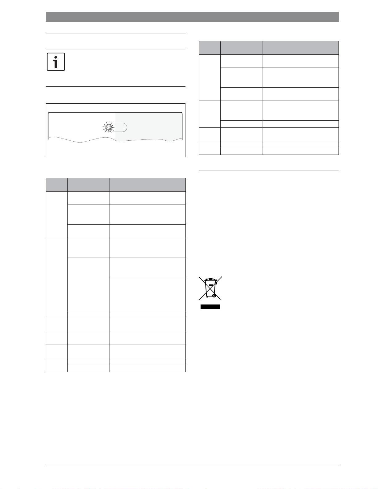
Eliminate fault | 19
0
1
2
3
4
5
6
7
8
9
10
5 Eliminate fault
Only use original spare parts. Any damage resulting from
spare parts that are not supplied by the manufacturer is
excluded from liability.
If a fault cannot be rectified, please contact the responsible
service engineer.
The indicator shows the operating condition of the module.
6 720 647 922-52.1O
5.1 Status indicator on the individual installed or higherlevel cascade module
Operating
Icon
Constantly
OFF
Constantly
red
Flashing
red
Flashing
green
Flashing
yellow
Constantly
green
Table 7
Possible cause Remedy
Power supply
▶ Turn on the mains power supply.
interrupted.
Fuse faulty. ▶ When the power supply is switched
off, replace the fuse (Æ fig. 21,
page 89)
Short circuit in BUS
connection.
Coding card in invalid
▶ Check BUS connection and repair if
required.
▶ Set the coding card.
position or in
intermediate position.
Temperature sensor is
defective
▶ Check temperature sensor.
▶ If values do not match, replace the
sensor
▶ Check voltage at temperature sensor
terminals in the module.
▶ If the sensor values match but the
voltage values do not match, replace
the module.
Internal fault ▶ Replace module.
Stop switch on I3 is
▶ Check the stop switch.
open
Switch for max.
Check max switch on I2
performance is closed
Initialisation –
Coding card set to 0 ▶ Set the coding card.
No fault Normal operation
5.2 Status indicator on the lower-level cascade module
Indicator
light
Constantly
OFF
Possible cause Remedy
Power supply
▶ Switch on the power supply.
interrupted.
Fuse faulty. ▶ When the power supply is switched
off, replace the fuse (Æ fig. 21,
page 89)
Constantly
red
Short circuit in BUS
connection.
Coding card in invalid
position or in
▶ Check BUS connection and repair if
required.
▶ Set the coding card.
intermediate position.
Internal fault. ▶ Replace module.
Flashing
Initialisation –
yellow
Constantly
green
Coding card set to 0. ▶ Set the coding card.
No fault Normal mode
Table 8
6 Environment / disposal
Environmental protection is a fundamental corporate strategy of the
Bosch Group.
The quality of our products, their efficiency and environmental safety
are all of equal importance to us and all environmental protection
legislation and regulations are strictly observed.
We use the best possible technology and materials for protecting the
environment taking into account economic considerations.
Packaging
We participate in the recycling programmes of the countries in which our
products are sold to ensure optimum recycling.
All of our packaging materials are environmentally friendly and can be
recycled.
Old electrical and electronic appliances
Electrical or electronic devices that are no longer
serviceable must be collected separately and sent for
environmentally compatible recycling (in accordance
with the European Waste Electrical and Electronic
Equipment Directive).
To dispose of old electrical or electronic devices, you
should use the return and collection systems put in place
in the country concerned.
6 720 819 669 (2016/05)MC 400
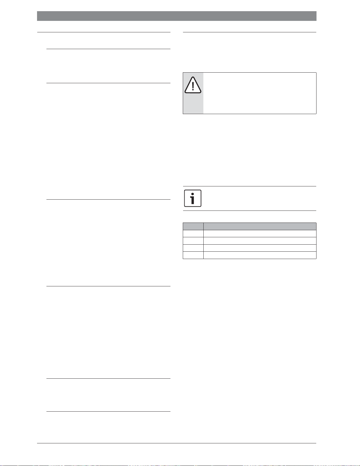
20 | Índice
Índice
1 Explicación de la simbología y instrucciones
de seguridad . . . . . . . . . . . . . . . . . . . . . . . . . . . . . . . . . . . . . . . . . 20
1.1 Explicación de los símbolos . . . . . . . . . . . . . . . . . . . . . . . 20
1.2 Indicaciones generales de seguridad . . . . . . . . . . . . . . . 20
2 Datos sobre el producto . . . . . . . . . . . . . . . . . . . . . . . . . . . . . . . . 21
2.1 Avisos importantes para el uso . . . . . . . . . . . . . . . . . . . . 21
2.2 Descripción del funcionamiento . . . . . . . . . . . . . . . . . . . 21
2.2.1 Principio básico . . . . . . . . . . . . . . . . . . . . . . . . . . . . . . . . 21
2.2.2 Límites temporales . . . . . . . . . . . . . . . . . . . . . . . . . . . . . . 22
2.3 Estrategias de regulación . . . . . . . . . . . . . . . . . . . . . . . . . 22
2.3.1 Cascada en serie estándar . . . . . . . . . . . . . . . . . . . . . . . . 22
2.3.2 Cascada en serie optimizada . . . . . . . . . . . . . . . . . . . . . . 22
2.3.3 Cascada en serie para las cargas pico . . . . . . . . . . . . . . . 22
2.3.4 Cascada en paralelo . . . . . . . . . . . . . . . . . . . . . . . . . . . . . 22
2.3.5 Regulación de la potencia . . . . . . . . . . . . . . . . . . . . . . . . 22
2.3.6 Regulación de la temperatura de impulsión . . . . . . . . . . 22
2.3.7 Avance de la bomba . . . . . . . . . . . . . . . . . . . . . . . . . . . . . 23
2.4 Ajuste de la ruleta codificadora de direcciones . . . . . . . 23
2.5 Volumen de suministro . . . . . . . . . . . . . . . . . . . . . . . . . . 23
2.6 Datos técnicos . . . . . . . . . . . . . . . . . . . . . . . . . . . . . . . . . 23
2.7 Accesorio adicional . . . . . . . . . . . . . . . . . . . . . . . . . . . . . 23
2.8 Limpieza . . . . . . . . . . . . . . . . . . . . . . . . . . . . . . . . . . . . . . 23
3 Instalación . . . . . . . . . . . . . . . . . . . . . . . . . . . . . . . . . . . . . . . . . . . 24
3.1 Instalación . . . . . . . . . . . . . . . . . . . . . . . . . . . . . . . . . . . . . 24
3.2 Instalación de un sensor de temperatura en el
compensador hidráulico . . . . . . . . . . . . . . . . . . . . . . . . . 24
3.3 Conexión eléctrica . . . . . . . . . . . . . . . . . . . . . . . . . . . . . . 24
3.3.1 Conexión entre conexión de BUS y la sonda
de temperatura (lado de baja tensión) . . . . . . . . . . . . . . 24
3.3.2 Conexión alimentación bomba y mezclador
(lado de tensión de red) . . . . . . . . . . . . . . . . . . . . . . . . . 24
3.3.3 Esquemas de conexiones con ejemplos
de instalación . . . . . . . . . . . . . . . . . . . . . . . . . . . . . . . . . . 25
3.3.4 Vista general de la asignación de los bornes
de conexión . . . . . . . . . . . . . . . . . . . . . . . . . . . . . . . . . . . 25
4 Puesta en marcha . . . . . . . . . . . . . . . . . . . . . . . . . . . . . . . . . . . . . 26
4.1 Ajuste de la ruleta codificadora de direcciones . . . . . . . 26
4.2 Puesta en marcha de la instalación y del módulo . . . . . . 26
4.2.1 Ajustes de instalaciones con un módulo de cascada
en el sistema BUS . . . . . . . . . . . . . . . . . . . . . . . . . . . . . . 26
4.2.2 Ajustes ende instalaciones con 2 o más módulos
de cascada en el sistema BUS . . . . . . . . . . . . . . . . . . . . 26
4.3 Visualización de estado para generador de calor /
módulos de cascada de orden inferior en el módulo
de cascada de orden superior . . . . . . . . . . . . . . . . . . . . . 27
4.4 Visualización de estado de los generadores de calor
en módulo de cascada de orden inferior . . . . . . . . . . . . 27
4.5 Menú Ajustes cascada . . . . . . . . . . . . . . . . . . . . . . . . . . . 27
4.6 Menú diagnóstico . . . . . . . . . . . . . . . . . . . . . . . . . . . . . . . 27
5 Subsanación de las averías . . . . . . . . . . . . . . . . . . . . . . . . . . . . . 28
5.1 Testigo luminoso en un módulo de cascada
individualmente instalado o de orden superior . . . . . . . 28
5.2 Testigo luminoso en un módulo o de orden inferior . . . . 28
6 Protección del medio ambiente/reciclaje . . . . . . . . . . . . . . . . . 28
1 Explicación de la simbología y instrucciones de
seguridad
1.1 Explicación de los símbolos
Advertencias
Las advertencias están marcadas en el texto con un
triángulo.
Adicionalmente las palabras de señalización indican el
tipo y la gravedad de las consecuencias que conlleva la
inobservancia de las medidas de seguridad indicadas
para evitar riesgos.
Las siguientes palabras de señalización están definidas y pueden utilizarse en el presente documento:
• AVISO advierte sobre la posibilidad de que se produzcan daños
materiales.
• ATENCIÓN advierte sobre la posibilidad de que se produzcan daños
personales de leves a moderados.
• ADVERTENCIA advierte sobre la posibilidad de que se produzcan
daños personales de graves a mortales.
• PELIGRO advierte sobre daños personales de graves a mortales.
Información importante
La información importante que no conlleve riesgos personales o materiales se indicará con el símbolo que se
muestra a continuación.
Otros símbolos
Símbolo Significado
▶ Procedimiento
Æ Referencia cruzada a otro punto del documento
• Enumeración/punto de la lista
– Enumeración/punto de la lista (2.º nivel)
Tab. 9
1.2 Indicaciones generales de seguridad
Este manual de instalación se dirige a los técnicos de instalaciones
hidráulicas, técnica calefactora y en electrotécnica.
▶ Leer los manuales de instalación (generador de calor, modulos, etc.)
antes de la instalación.
▶ Tener en cuenta las advertencias e indicaciones de seguridad.
▶ Tener en cuenta la normativa nacional y regional y las normas y direc-
tivas técnicas.
▶ Documentar los trabajos que se efectúen.
Uso conforme al empleo previsto
▶ Utilizar el producto únicamente para la regulación de instalaciones
de calefacción con sistemas en cascada. En un sistema en cascada se
aprovecha de varios generadores de calor para alcanzar una potencia
calorífica mayor.
Cualquier otro uso se considera inapropiado. La empresa no asume nin-
guna responsabilidad por los daños causados por el uso inapropiado del
calentador.
Instalación, puesta en marcha y mantenimiento
La instalación, la puesta en marcha y el mantenimiento únicamente
puede efectuarlos una empresa autorizada.
▶ No instalar el producto en espacios con humedad.
▶ Instalar únicamente piezas de repuesto originales.
MC 4006 720 819 669 (2016/05)

Datos sobre el producto | 21
Trabajos eléctricos
Los trabajos eléctricos deben realizarlos únicamente técnicos especializados.
▶ Antes de realizar trabajos eléctricos:
– Desconectar la tensión de red (en todos los polos) y asegurar el
aparato contra una reconexión.
– Comprobar que la instalación está sin tensión.
▶ El producto requiere diferentes tensiones.
No conectar el lado de muy baja tensión a la tensión de red y viceversa.
▶ Tener en cuenta en todo caso los esquemas de conexión de otras
partes de la instalación.
Entrega al usuario
En el momento de la entrega instruir al usuario sobre el manejo y las condiciones de servicio de la instalación de calefacción.
▶ Aclarar las condiciones - poner especial énfasis en las acciones rele-
vantes para la seguridad.
▶ Advertir de que las modificaciones o reparaciones solo pueden lle-
varlas a cabo un servicio técnico autorizado.
▶ Advertir de la necesidad de inspección y mantenimiento para un ser-
vicio seguro y ambientalmente sostenible.
▶ Entregar los manuales de servicio y de instalación al usuario para su
conservación.
Daños por heladas
La instalación podría congelarse si no está en funcionamiento:
▶ Observar las indicaciones relativas a la protección contra heladas.
▶ La instalación siempre debe estar conectada debido a funciones adi-
cionales, por ejemplo, producción de agua caliente o sistema antibloqueo.
▶ Reparar de inmediato las averías que surjan.
2 Datos sobre el producto
El módulo sirve para la regulación de sistemas en cascada. Un sistema en
cascada es un sistema de calefacción en el que se utilizan varios generadores de calor para obtener una potencia calorífica mayor. Véase para
ello p.ej. el esquema de conexión en la página 90.
• El módulo sirve para la activación del generador de calor.
• El módulo sirve para registrar la temperatura de retorno, de alimentación y exterior.
• Configuración de sistemas en cascada con una unidad de mando con
interfaz BUS EMS 2 / EMS plus (no es posible con todas las unidades
de mando).
Las posibilidades de combinación de los módulos están visibles en los
esquemas de conexiones.
2.1 Avisos importantes para el uso
El módulo se comunica a través de una interfaz EMS 2 / EMS plus con
otras unidades de BUS compatibles con EMS 2 / EMS plus.
En caso de que en generadores de calor con bomba regulada por el número de revoluciones el número de revoluciones, es insuficiente al momento del arranque del quemador,
pueden producirse altas temperaturas y un arranque frecuente del quemador.
▶ En caso de ser posible, configurar la bomba en funciona-
miento CON/DES con 100 % de potencia, caso contrario
ajustara la potencia mínima de la bomba en el mayor
valor posible.
• El módulo puede conectarse a controles externos con interfaz de
BUS EMS 2/EMS plus (sistema de gestión de energía). Alternativamente se puede conectar un requerimiento de potencia o de temperatura al módulo mediante el interfaz 0-10 V.
• El módulo sólo comunica con generadores de calor con EMS, EMS 2,
EMS plus y BUS de 2 hilos (HTIII) (exceptuando generadores de calor
de las GB112, GB132, GB135, GB142, GB152).
• Conectar sólo generadores de calor del mismo fabricante.
• Utilizar únicamente generadores de calor alimentados por gas o sólo
generadores de calor alimentados por gasóleo en una misma instalación (no permitido bombas de calor con interfaz BUS EMS 2/
EMS plus).
• El lugar de instalación debe ser apto para la clase de protección
según los datos técnicos del módulo.
• Si se conecta un acumulador de agua caliente directamente a un
generador de calor:
– El regulador del sistema o el regulador 0-10 V no emite informa-
ciones acerca del sistema de agua caliente y no tiene influencia en
la producción de agua caliente.
– Se recomienda utilizar un acumulador menor de 400 litros al tra-
bajar con una producción de agua caliente.
– El agua caliente, incluyendo desinfección térmica, se controla
directamente desde el generador de calor.
– La desinfección térmica debe ser controlada manualmente.
Tener en cuenta las instrucciones del generador de calor.
– Si no es posible controlar la desinfección térmica en el aparato no
se debe conectar un acumulador de agua caliente directamente al
generador de calor.
2.2 Descripción del funcionamiento
2.2.1 Principio básico
El módulo gestiona la potencia total de la cascada, dependiendo de la
diferencia de temperatura entre la temperatura de impulsión (en el compensador hidráulico) y la temperatura nominal del sistema. Para ello se
conectan o desconectan en secuencia diferentes aparatos. Los aparatos
siempre se gestionan mediante una indicación de potencia y obtiene
como valor teórico de temperatura la máxima temperatura teórica posible. Antes de conectar un aparato, el módulo activa la bomba de calefacción durante 2 minutos para calentar el aparato a la temperatura de
servicio.
Cada aparato causa un enorme salto de potencia al conectarlo o desconectarlo. El módulo utiliza el aparato previamente conectado para reducir el salto de potencia.
Para ello el módulo hace modular primero el primer aparato hasta la
potencia máxima. En caso de conectar un aparato adicional baja simultáneamente la potencia del primer aparato. De esa manera el segundo
aparato no produce un salto en la potencia general. En caso de necesitar
una mayor potencia, el módulo incrementa la potencia del primer aparato. El segundo permanece en la potencia mínima. En el momento en el
que el primer aparato alcanza la potencia máxima, se activa la modulación en el segundo aparato. Esto continúa según el requerimiento respectivo de potencia hasta que se hayan activado todos los aparatos con
la potencia máxima.
En caso de que la potencia total sea demasiado fuerte, el módulo reduce
la potencia del último aparato conectado hasta la potencia mínima. A
continuación se modula el aparato que arrancó previamente (que todavía está funcionando a potencia máxima) hasta que se reduce la potencia restante del último aparato. Justo en ese momento se desconecta el
último aparato y simultáneamente se fija el penúltimo en la potencia
máxima. De esa manera se evita una reducción repentina de la potencia
general. En caso de que la temperatura de servicio sea demasiado alta,
esto continua hasta haber desconectado todos los aparatos. Una vez
que finaliza la demanda de calor, se apagan simultáneamente todos los
aparatos.
6 720 819 669 (2016/05)MC 400
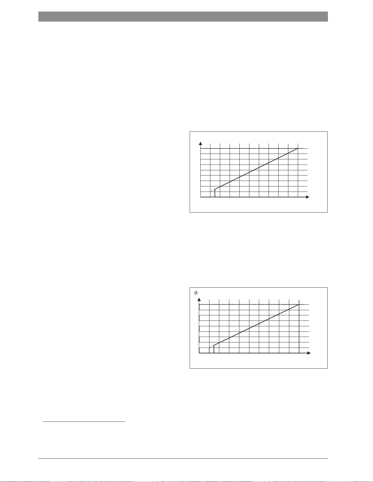
22 | Datos sobre el producto
2.2.2 Límites temporales
En caso de necesitar una potencia mayor a lo que puede producir un
generador de calor o la temperatura se encuentre debajo de la temperatura nominal,
nible después de un tiempo definido
1)
el módulo conecta el siguiente generador de calor dispo-
2)
.
Después del iniciar un generador de calor adicional, el módulo espera
1½ minutos hasta que se realice el siguiente incremento de potencia.
Esto evita principalmente un sobreimpulso de la temperatura.
Este principio básico vale sólo para las funciones con la codificación 1
hasta 4 y 8 hasta 9. Con estas funciones el módulo regula siempre según
la temperatura teórica en el sistema y la sub/sobretemperatura tolerada
sirve como diferencia de conmutación para los generadores de calor.
2.3 Estrategias de regulación
2.3.1 Cascada en serie estándar
Los generadores de calor / módulos conectados son conectados o desconectados según el cableado.
P.ej. se conecta el generador de calor en el borne de conexión BUS1 como
primero, el generador de calor en el borne BUS2 como segundo, etc.
Al desconectar los generadores de calor, la secuencia es al revés.
El último generador desconectado será conectado como primero.
La regulación considera que la competencia transmitida aumenta o cae
súbitamente al conectar o desconectar un generador de calor.
2.3.2 Cascada en serie optimizada
El objetivo de esta estrategia de regulación es tratar de activar los generadores de calor con los mismos tiempos de marcha de los quemadores.
Los generadores de calor conectados son conectados o desconectados
según el tiempo de marcha de los quemadores. El sistema compara los
tiempos de marcha de los quemadores cada 24 horas, definiendo así
nuevamente su secuencia.
El generador de calor con el menor tiempo de marcha es el primero en
ser conectado, el del mayor tiempo de marcha como último.
Al desconectar los generadores de calor, la secuencia es al revés.
El último generador desconectado será conectado como primero.
La regulación considera que la potencia transmitida aumenta o cae
súbitamente al conectar o desconectar un generador de calor
(Æ cap. 2.2.1).
2.3.3 Cascada en serie para las cargas pico
Esta estrategia de regulación tiene sentido si la carga de calefacción es
constante durante la mayor parte del tiempo (carga básica) y aumenta
por poco tiempo (demanda pico).
Los generadores de calor en los bornes de conexión BUS1 y BUS2
cubren la carga básica. Los generadores de calor en los bornes de
conexión BUS3 y BUS4 se conectan para cumplir con el consumo de
energía para la demanda pico.
El sistema conecta los generadores de calor en los bornes de conexión
BUS3 y BUS4 cuando la temperatura de impulsión requerida sube más
allá del valor límite ajustable o la temperatura exterior cae por debajo de
un valor límite ajustable.
Al desconectar los generadores de calor, la secuencia es al revés.
El último generador desconectado será conectado como primero.
La regulación considera que la potencia transmitida aumenta o cae
súbitamente al conectar o desconectar un generador de calor
(Æ cap. 2.2.1).
1) Falta de temperatura tolerada, gama de ajuste 0-10 K, ajuste de fábrica 5 K
(no se utiliza para la regulación de la potencia)
2) Retraso de inicio aparato siguiente, gama de ajuste 0-15 minutos, ajustes de
fábricas 6 minutos
2.3.4 Cascada en paralelo
Esta estrategia de regulación debe usarse cuando los generadores de
calor tienen un grado de modulación similar.
En caso de haber alcanzado en un aparato conectado 68 % de la potencia, se conectará el siguiente.
De esa manera se utiliza los generadores de calor con aproximadamente
los mismos tiempos de quemador, debido a que por lo general todos los
generadores de calor están conectados simultáneamente. En caso de
haber conectado todos los generadores de calor, se los controla de una
manera coordinada.
2.3.5 Regulación de la potencia
Esta estrategia de regulación se aplica cuando la instalación de calefacción se regula mediante una técnica de transmisión en el edificio con una
salida de regulación 0 - 10 V.
P / %
100
10
1
1,5 10
U / V
6 720 809 449-21.1O
Fig. 1 Relación lineal entre la señal 0-10 V (U en voltios) y la potencia
P solicitada (en porcentaje en relación al rendimiento máximo
de la planta)
Los generadores de calor se conectan y desconectan según el rendimiento solicitado y según la codificación del módulo como al igual que en
el estándar en serie o en la cascada en serie optimizada.
2.3.6 Regulación de la temperatura de impulsión
Esta estrategia de regulación se aplica cuando la instalación de calefacción se regula mediante un sistema de gestión en el edificio con una
salida de regulación 0 - 10 V.
/ °C
90
20
1
1,5 10
Fig. 2 Relación lineal entre señal 0-10 V (U en Volt) y la temperatura
de impulsión requerida - (en °C relación del sector de la temperatura mínima de impulsión hasta una temperatura máxima
de impulsión [Ajuste de fábrica 20 °C hasta 90 °C])
Los generadores de calor conectados se conectan y desconectan según
la temperatura de impulsión solicitada y según la codificación del
módulo como al igual que en el estándar en serie o en la cascada en serie
optimizada.
U / V
6 720 809 449-22.2O
MC 4006 720 819 669 (2016/05)
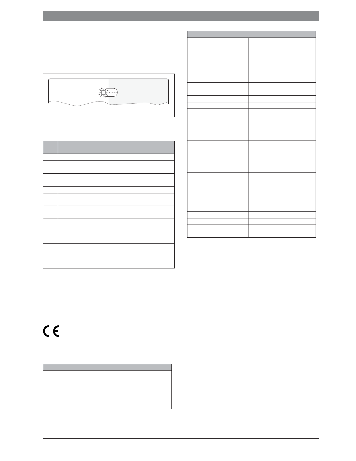
Datos sobre el producto | 23
0
1
2
3
4
S
Y
I
2.3.7 Avance de la bomba
En todas las estrategias de regulación (Æ cap. 2.3.1 hasta 2.3.6) se
realiza un arranque de bombas de 2 minutos antes de iniciar el quemador en los generadores de calor. Esto reduce los gradientes de temperatura en el avance y evita la activación del control de gradientes.
2.4 Ajuste de la ruleta codificadora de direcciones
6 720 810 538-23.1O
Fig. 3 Interruptor codificador con visualización de estado del
módulo y visualización de estado de los módulos o generadores
de calor conectados
Codifi-
Función del módulo
cación
0 DES (estado de entrega)
1 Cascada en serie estándar
2 Cascada serial optimizada (Æ fig. 24, página 89)
3 Cascada en serie para las cargas pico
4 Cascada en paralelo
5 Sin función
6 Regulación externa de potencia 0-10 V con cascada serial estándar
(sin regulación interna de temperatura)
7 Regulación externa de potencia 0-10 V con cascada serial optimizada
(Æ fig. 25, página 90, sin regulación interna de temperatura)
8 Regulación de temperatura de impulsión externa 0-10 V con cascada
serial estándar
9 Regulación de temperatura de impulsión externa 0-10 V con cascada
serial optimizada
10 El módulo es uno de máximo 4 módulos de cascada de orden inferior.
El módulo de cascada de orden superior regula los generadores de
calor conectados según la codificación configurada (Æ fig. 26,
página 90).
Tab. 10 Codificación y función
2.5 Volumen de suministro
Fig. 5, pág. 86:
[1] Módulo
[2] Bolsa con retenedores de cable
[3] Manual de instalación
2.6 Datos técnicos
La construcción y el funcionamiento de este producto cumplen con las directivas europeas, así como con los requisitos
complementarios nacionales. La conformidad se ha probado con la marca CE. Puede solicitar la declaración de conformidad del
producto. Para ello, diríjase a la dirección que se encuentra en la página
posterior de estas instrucciones.
Datos técnicos
Dimensiones (A × AN × P) 246 × 184 × 61 mm (más dimensio-
nes Æ figura 6, página 86)
Sección máxima de cable
• Borne de conexión de 230 V
• Borne de conexión de tensión
baja tensión
Tab. 11
• 2,5 mm
• 1,5 mm
2
2
Datos técnicos
Tensiones nominales
• BUS
• 15 V CC (a prueba de polarización
inversa)
• Tensión de red módulo
• Regulador de ventilador
• 230 V CA, 50 Hz
• 15 V CC (a prueba de polarización
inversa)
• Bombas y mezclador
• 230 V CA, 50 Hz
Protección 230 V, 5 AT
Interfaz de BUS EMS 2 / EMS plus
Consumo de potencia – standby < 1,0 W
Potencia máxima admisible 1100 W
Máx. potencia admisible por
conexión
• PC0, PC1
• 400 W (efectivo para bombas de
alta eficiencia; máx. 40 A/μs)
• A0, IA1
• 10 W
Rango de medición sonda de
impulsión y retorno
• Límite inferior de error
• Zona de indicación
• Límite superior de error
• < – 10 °C
• 0 ... 100 °C
• > 125 °C
Rango de medición sonda de temperatura exterior
• Límite inferior de error
• Zona de indicación
• Límite superior de error
• < – 35 °C
• – 30 ... 50 °C
• > 125 °C
Temperatura ambiente admisible 0 ... 60 °C
Clase de protección IP44
Clase de protección I
N.º ident. Placa de características (Æ fig. 23,
pág. 89)
Tab. 11
2.7 Accesorio adicional
Encontrará información más detallada respecto a los accesorios adecuados en el catálogo.
• Unidad de mando: regulador guiado por la temperatura exterior con
sonda de temperatura exterior o aparato de regulación guiado por la
temperatura ambiente; conexión a BUS (no conectar a BUS1, BUS2,
BUS3 o BUS4); conexión de sonda de temperatura exterior a T1
• Conexión de sonda de temperatura de impulsión a T0
• Conexión de sonda de temperatura exterior a T1
• Conexión de sonda de temperatura de retorno a T2
• Conexión de bomba de cascada a PC0
• Bomba de calefacción; conexión a PC1
• Interruptor para carga máxima; conexión a I2
• Conexión de interruptor de parada a I3
• IGM para generador de calor sin EMS, EMS 2 o EMS plus; conexión
según documentación técnica del IGM (el módulo de cascada
MC 400 reemplaza al ICM)
Instalación de accesorios adicionales
▶ Instalar los accesorios adicionales según las normativas legales y las
instrucciones suministradas.
2.8 Limpieza
▶ En caso necesario, frotar con un paño húmedo. No utilizar productos
de limpieza fuertes o corrosivos.
6 720 819 669 (2016/05)MC 400
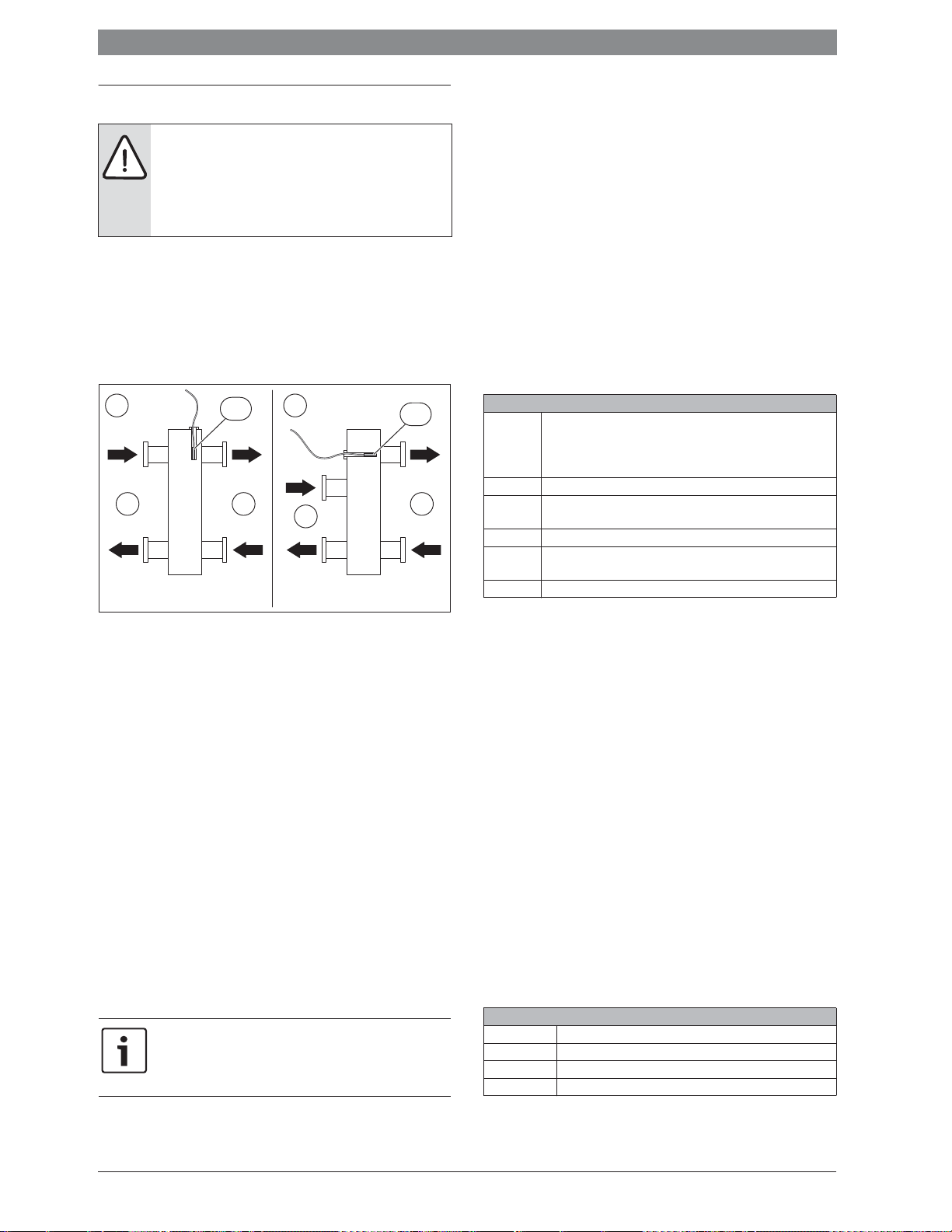
24 | Instalación
3 Instalación
PELIGRO: ¡Electrocución!
▶ Antes de instalar el producto: desconectar todos los
polos del generador de calor y todas las demás unidades de BUS de la tensión de red.
▶ Antes de la puesta en marcha: colocar la cubierta
(Æ figura 22, página 89).
3.1 Instalación
▶ Instalar módulo en una pared (Æ fig. 7 hasta imagen 9, a partir de la
página 86), en un perfil DIN (Æ fig. 10, página 86) o en un grupo
constructivo.
▶
Al retirar el módulo del perfil DIN, observar la figura
11
de la página
87
.
3.2 Instalación de un sensor de temperatura en el
compensador hidráulico
A
ϑ
1
1 2
T0
B
ϑ
3
ϑ
1
T0
ϑ
3
2
1
ϑ
2
Fig. 4 Posición sensor de temperatura de impulsión (T0)
[1] Todos los generadores de calor
[2] Todos los circuitos de calefacción
A Compensador hidráulico modelo 1
B Compensador hidráulico modelo 2
Temperatura de impulsión conjunta todos los generadores de calor
-
1
-2Temperatura de retorno conjunta de todos los generadores de calor
-3Temperatura de impulsión conjunta de todos los circuitos de
calefacción
-
Temperatura de retorno conjunta de todos los circuitos de cale-
4
facción
T
Sensor de temperatura alimentación en el compensador hidráulico
0
Posicionar el T0 de tal manera que se registra -3 independientemente
del caudal volumétrico en el lado de todos los generadores de calor [1].
Sólo de esa manera puede trabajar la regulación de manera estable, aún
con cargas reducidas.
3.3 Conexión eléctrica
▶ Teniendo en cuenta la normativa vigente sobre conexiones, utilizar
como mínimo cables eléctricos del tipo H05 VV-…
3.3.1 Conexión entre conexión de BUS y la sonda de temperatura
(lado de baja tensión)
Conexión de BUS general
Si se excede la longitud máxima de los cables de las conexiones de BUS entre todas las unidades de BUS, o bien existe
una estructura anular en el sistema de BUS, no se puede poner en marcha la instalación.
Longitud total máxima de las conexiones de BUS:
• 100 m con 0,50 mm
• 300 m con 1,50 mm
ϑ
2
de sección de cable
2
de sección de cable
ϑ
4
2
ϑ
4
6 720 809 449-24.1O
Conexión de BUS generador de calor – módulo de cascada
▶ Conectar el generador de calor y módulos de cascada de orden infe-
rior directamente a los bornes de conexión BUS1 ... BUS4 (Æ vista
general de las asignaciones de los bornes de conexión).
Conexiones de BUS módulo de cascada – unidad de mando –
otros módulos
▶ En caso de que las secciones de los cables sean diferentes: utilizar
una caja de distribución para conectar las unidades de BUS.
▶ Participante de BUS [B] mediante caja del distribuidor [A] en estrella
(Æ fig. 20, página 88, tener en cuenta las indicaciones de la unidad
de mando y de los demás módulos).
Sonda de temperatura
En caso de prolongar los cables del sensor, utilizar las siguientes secciones de cable:
• Hasta 20 m con 0,75 mm
• 20 m hasta 100 m con 1,50 mm
2
hasta 1,50 mm2 de sección de cable
2
de sección de cable
Generalidades en cuanto al lado de baja tensión
Designaciones de los bornes de conexión (lado de baja tensión d 24 V)
0-10 V Conexión
2)
BUS
BUS1...4 Conexión generador de calor o módulos de cascada de orden
I2, I3 Conexión interruptor externo (Input)
OC1 Conexión
T0, T1, T2 Conexión sonda de temperatura (Temperature sensor)
1)
para regulador de temperatura 0-10 V o regulación
superior del edificio con una salida de regulador 0-10 V adicionalmente retroalimentación de carga como señal 0-10 V para la regulación superior del edificio en el borne de conexión 3
Conexión a regulador, módulos
inferior
3)
regulación de revoluciones bomba con 0-10 V
(Output Cascade)
Tab. 12
1) Distribución de bornes: 1 – masa; 2 – entrada 0-10 V (Input) para demanda de
calor de la regulación superior del edificio; 3 – salida 0-10 V (Output, opcional)
para retroalimentación
2) En algunos aparatos, el borne de conexión está identificado para el sistema BUS
con EMS.
3) Distribución de bornes: 1 – masa; 2 – Salida PWM (Output); 3 – Entrada PWM
(Input, opcional)
▶ En caso de utilizar PO para la regulación, no bypasear IA1. En caso de
bypasear IA1 y PO está abierto, se regula a la máxima temperatura de
impulsión ajustada.
▶ Para evitar influencias inductivas: tender todos los cables de muy
baja tensión separados de los cables conductores de tensión de red
(distancia mínima 100 mm).
▶ En caso de influencias inductivas externas apantallar el cable y poner
a tierra el apantallamiento por un lado. No conectar el apantallamiento al borne de conexión de protección del módulo, sino a la toma
de tierra de la casa, por ejemplo, bornes libres para protecciones o
tuberías del agua.
▶ Introducir los cables por las abrazaderas de goma premontadas y
conectarlos según los esquemas de conexiones.
3.3.2 Conexión alimentación bomba y mezclador
(lado de tensión de red)
Designaciones de los bornes de conexión (lado de tensión de red)
120/230 V AC Conexión de tensión de red
PC0, PC1 Bomba de cascada (Pump Cascade)
A0 Conexión para aviso de fallo (Alert)
IA1 Conexión para regulador CON/DES 230 V)
Tab. 13
MC 4006 720 819 669 (2016/05)
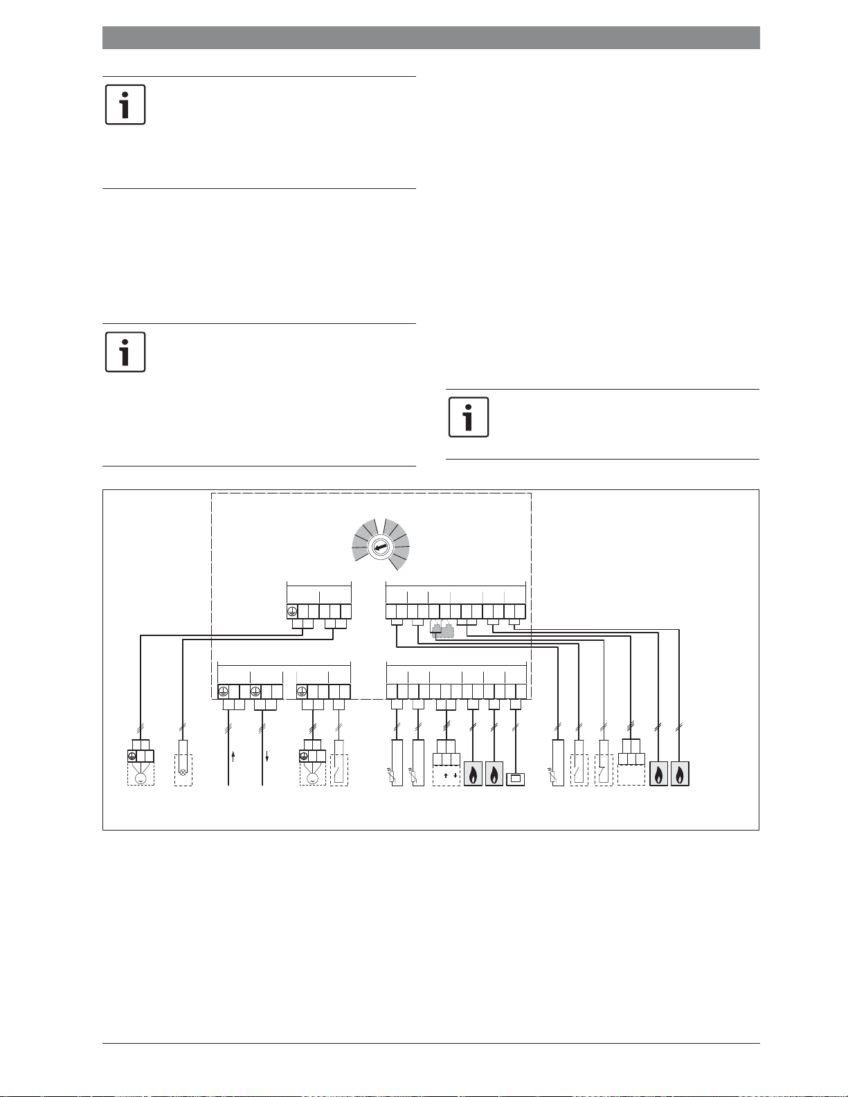
Instalación | 25
0
1
2
3
4
5
6
7
8
9
10
La asignación de las conexiones eléctrica depende de la instalación utilizada. Las descripciones representadas de la
figura 13 a 20, a partir de la página 87 son una propuesta
para el desarrollo de la conexión eléctrica. Los pasos de manipulación están representados en diferentes colores. De
esta manera es más fácil reconocer qué pasos de manipulación corresponden con otros.
▶ Utilizar solo cables eléctricos de la misma calidad.
▶ Prestar atención a la instalación correcta de las fases en la conexión
a red.
No está permitida una conexión a red mediante un conector de
puesta a tierra.
▶ En las salidas solo deben conectarse componentes y grupos cons-
tructivos según estas instrucciones. No conectar ningún otro control
adicional que accione otras partes de la instalación.
El consumo de potencia máximo de los componentes y grupos constructivos conectados no debe superar la potencia
admisible del módulo indicada en los datos técnicos.
▶ Si la alimentación de tensión de red no se lleva a cabo a
través del sistema electrónico del generador de calor, el
cliente debe instalar un dispositivo de desconexión para
todos los polos conforme a la normativa (según
EN 60335-1) para interrumpir la alimentación de
tensión de red.
▶ Introducir los cables por las abrazaderas de goma premontadas y
conectarlos según los esquemas de conexiones, además deben asegurarse con los retenedores de cables incluidos en el volumen de
suministro (Æ figuras 12 a 19, a partir de la página 87).
3.3.3 Esquemas de conexiones con ejemplos de instalación
Las presentaciones hidráulicas son solo esquemáticas y ofrecen un
aviso no vinculante sobre una posible conexión hidráulica. Usar los dispositivos de seguridad según las normas válidas y las prescripciones
locales. Para más información y opciones consultar a su delegación
correspondiente.
3.3.4 Vista general de la asignación de los bornes de conexión
La vista general indica los elementos de instalación que deben conectarse en todos los bornes de conexión del módulo. Los componentes
identificados con * (p. ej. HS1 y M1) son considerados como alternativa.
Dependiendo del uso del módulo se conecta un componente en el borne
de conexión “BUS1”.
Instalaciones más complejas se realizan en combinación con otros
módulos de cascada. Para ello es posible desarrollar distribuciones de
bornes de conexión que difieran de la vista general de los bornes de
conexión.
En caso de no estar conectado un interruptor de parada
(desconector) al borne de conexión I3:
▶ Conectar el puente al borne de conexión I3 entregado en
el volumen de suministro.
MC400
PC0
NL
M
120/230 V AC
120/230VAC 120/230VAC
NL N LINN63L
120/230 V AC
A0
PC0
CNO NC
N63
PC1 IA1
NL
M
PC1
1)
10
≤ 24V
BUS3 BUS4
T0 I2 I3
OC1
123
1)
1212121212
≤ 24V
T2 BUS1
T1
1212
T1 T0
0-10V
123
123
(-) (+) (+)
PO
12 12
HS1*
M1*
BUS2
12
HS5*
M2*
BUS
CONT2IA1A0
Leyenda de la figura superior y de las figuras 24 hasta 26 (sin designación de los bornes de conexión):
230 V CA Conexión de tensión de red
A0 Indicación de fallo remoto 230 V de la instalación
BUS Sistema de BUS EMS 2/ EMS plus (no conectar a BUS1 ...
BUS4 )
BUS1...4 Sistema de BUS EMS / EMS plus o bus EMS 2 / 2 (conectar
directamente a HS1 ... HS4 o M1 ... M4)
CON Unidad de mando con sistema de BUS EMS 2 / EMS plus
(Controlador)
GLT Regulación superior del edificio con interfaces 0-10 V
(Telegestión)
HS1, HS5, HS9, HS13
Generador de calor 1 (HS1 a BUS1), 2 (HS5 a BUS2),
3 (HS9 a BUS3) y 4 (HS13 a BUS4) en un solo MC 400 /
(Generador)
HS1...4 Generador de calor 1 (en BUS1) ... 4 (en BUS4) al primer
MC 400 de orden inferior (M1) / (Generador)
HS5...8 Generador de calor 1 (en BUS1) ... 4 (en BUS4) segundo
MC 400 de orden inferior (M2) / (Generador)
I2 Interruptor para carga máxima (todos los aparatos trabajan al
máximo cuando se cierra; Input)
I3 Interruptor de parada (la demanda de calor en todos los
aparatos se interrumpe cuando se abre; Input)
123
0-10V
PC0
HS9*
I2 I3230 V AC230 V AC
M3*
HS13*
M4*
6 720 809 449-16.4O
6 720 819 669 (2016/05)MC 400
26 | Puesta en marcha
IA1 Entrada regulador CON/DES 230 V (codificación 6 ... 9)
M1...4 Módulo de cascada 1 de orden inferior (en BUS1) ...
4 (en BUS4)
MC 400 Módulo de cascada
MM 100 Módulo de circuito de calefacción (EMS 2 / EMS plus)
PC0 Bomba de cascada (CON/DES o regulación opcional de revo-
luciones mediante 0-10 V con conexión a OC1; Pump Cas-
cade); sólo en caso de generadores de calor sin bomba
PC1 Bomba de calefacción (Pump Circuit); sólo con un circuito
de calefacción directo sin MM 100 (bomba de alimentación o
de calefacción)
PO Entrada y salida para la regulación de potencia mediante una
señal 0-10 V (Power Input y Output); Distribución de bornes:
1 – 2 entrada; 1 – 3 salida)
T0 Sonda de impulsión (Temperature sensor)
T1 Sonda de temperatura, temperatura exterior (Temperature
sensor)
T2 Sonda de temperatura de retorno (sólo necesario si PC0 con
regulación de revoluciones se realiza mediante señal 0-10 V
en conexión OC1; de otra manera opcional; Temperature
sensor)
1) Sólo necesario si en el borne de conexión I3 no se conectó un
interruptor de parada.
4 Puesta en marcha
AVISO: Daño de planta por bomba averiada.
▶ Antes de realizar la conexión, llenar la instalación y
purgarla para que las bombas no marchen en vacío.
Conectar correctamente todas las conexiones eléctricas y,
solo entonces, realizar la puesta en marcha.
▶ Observar los manuales de instalación de todos los com-
ponentes y grupos constructivos de la instalación.
▶ Conectar la alimentación de tensión solo cuando todos
los módulos estén ajustados.
4.1 Ajuste de la ruleta codificadora de direcciones
Cuando la ruleta codificadora se encuentra en una posición válida y se
estableció la comunicación mediante el sistema BUS, el testigo luminoso
se ilumina de manera continua en verde. Cuando la ruleta codificadora
está en una posición inválida o intermedia, al principio el testigo luminoso no se ilumina y después en se ilumina en rojo.
Si en el módulo de orden superior MC 400 la ruleta codificadora se encuentra en 10 y consta una conexión directa de
BUS entre un generador de calor y este módulo, no será
posible poner en marcha la instalación.
4.2 Puesta en marcha de la instalación y del módulo
AVISO: Daño de planta por bomba averiada.
▶ Antes de realizar la conexión, llenar la instalación y
purgarla para que las bombas no marchen en vacío.
En caso de estar instalado un IGM, es necesario tener en
cuenta los siguientes puntos:
▶ Ajustar en el IGM la potencia mínima y máxima del gene-
rador conectado.
▶ Ajustar la potencia máxima por lo menos en 5 kW, debi-
do a que de otra manera la regulación de cascada no
recurre al IGM.
▶
En caso de que el aparato conectado es un aparato de dos
puntos, ajustar la potencia máxima = potencia mínima.
1. Desconectar la tensión de red (en todos los polos) y asegurar el
aparato contra una reconexión.
2. Asegurarse de que la instalación está libre de tensión.
3. Conectar todas las sondas y actuadores necesarios.
4. Establecer mecánicamente la alimentación eléctrica (230 V AC) en
todos los módulos y generadores de calor instalados.
4.2.1 Ajustes de instalaciones con un módulo de cascada en el
sistema BUS
1. Ajustar la estrategia de regulación con el interruptor codificador en el
módulo de cascada.
2.
En caso necesario, ajustar el interruptor codificador en otros módulos.
3. Conectar la alimentación de tensión (tensión de red) de la planta
general.
El módulo MC 400 detecta los generadores de calor conectados.
Dependiendo de la cantidad, esto puede durar hasta 5 minutos. En
este tiempo el sistema no reacciona a las órdenes de calefacción de
la unidad de mando. Tan pronto se reconoció el primer generador de
calor, el MC 400 activa la tensión de alimentación de la unidad de
mando con el sistema BUS EMS 2 / EMS plus (CON)
Cuando el testigo luminoso del módulo está iluminado permanentemente en verde:
4. Poner en marcha la unidad de mando conforme al manual de instalación adjunto y ajustarla de la manera correspondiente.
5. Colocar la influencia de la temperatura ambiente en la unidad de
mando en 0.
6. Controlar ajustes en la unidad de mando para la cascada y, en caso
dado, ajustarlo según la instalación.
4.2.2 Ajustes ende instalaciones con 2 o más módulos de cascada
en el sistema BUS
En una planta pueden estar instalados hasta 16 generadores de calor.
En estos casos consta un módulo de cascada de orden superior y 1 a 4
módulos de cascada de orden inferior.
1. Ajustar la estrategia de regulación con el interruptor codificador en el
módulo de cascada de orden superior.
2. Ajustar interruptor codificador en los módulos de cascada de orden
inferior en 10.
3.
En caso necesario, ajustar el interruptor codificador en otros módulos.
4. Conectar la fuente de alimentación de los generadores de calor.
5. Conectar la alimentación eléctrica para los módulos.
Los MC 400 detectan los generadores de calor registrados y, en caso
dado, otros MC 400 (módulos subordinados). Dependiendo de la
cantidad, esto puede durar hasta 5 minutos. En este tiempo el sistema no reacciona a las órdenes de calefacción de la unidad de
mando. Tan pronto se reconoció el primer generador de calor, el
MC 400 activa la tensión de alimentación de la unidad de mando con
el sistema BUS EMS 2 / EMS plus (CON).
6. Poner en marcha la unidad de mando conforme al manual de instalación adjunto y ajustarla de la manera correspondiente.
7. Colocar la influencia de la temperatura ambiente en la unidad de
mando en 0.
8. Controlar ajustes en la unidad de mando para la cascada y, en caso
dado, ajustarlo según la instalación.
MC 4006 720 819 669 (2016/05)
Puesta en marcha | 27
4.3 Visualización de estado para generador de calor /
módulos de cascada de orden inferior en el módulo de
cascada de orden superior
Junto a la ruleta codificadora se encuentran en el módulo 4 LEDs que
visualizan el respectivo estado del generador de calor / módulo conectado.
• LED 1, 2, 3 y 4 visualizan el estado del respectivo generador de
calor / módulo de cascada de orden subordinado conectado al
módulo:
– desconectado: conexión separada o ninguna comunicación
– rojo: se encontró generador de calor, pero se interrumpió la
conexión o fallo en el generador de calor
– amarillo: generador de calor conectado, no hay demanda de calor
– parpadea amarillo: se encontró generador de calor, consta
demanda de calor pero el quemador está desconectado
– verde: se encontró módulo de orden superior o un generador de
calor, consta demanda de calor, quemador en marcha, calefac-
ción activa
– parpadea verde: se encontró módulo de orden superior o un
generador de calor, consta demanda de calor, quemador en mar-
cha, producción de agua caliente activa
4.4 Visualización de estado de los generadores de calor
en módulo de cascada de orden inferior
Junto a la ruleta codificadora se encuentran en el módulo 4 LEDs que visualizan el respectivo estado del generador de calor / módulo conectado.
• LED 1, 2, 3 y 4 visualizan el estado de los generadores de calor res-
pectivos:
– desconectado: conexión separada o ninguna comunicación
– rojo: se encontró módulo de cascada o generadores de calor pero
se interrumpió la conexión o hay un fallo en el generador de calor
– amarillo: generador de calor conectado, no hay demanda de calor
– parpadea amarillo: se encontró generador de calor, consta
demanda de calor pero el quemador está desconectado (p. ej.
cuando el bloqueo del ciclo del generador de calor está activo)
– verde: se encontró generador de calor, consta demanda de calor,
quemador en marcha, calefacción activa
–
parpadea verde: se encontró generador de calor, consta demanda
de calor, quemador activo, producción de agua caliente activa
4.5 Menú Ajustes cascada
En caso de haber instalado un módulo de cascada se visualiza en la unidad de mando el menú Menú de servicio > Ajustes cascada (no disponible en todas las unidades de mando). En caso de que este menú no
esté disponible en la unidad de mando instalada, el módulo de cascada
se activa en ajuste de fábrica. Es posible modificar los ajustes con una
unidad de mando adecuada, incluso si la unidad de mando sólo está
conectada temporalmente.
Los ajustes de fábrica están resaltados en los sectores
de ajuste.
Opción de menú Campo de regulación Descripción del funcionamiento
Offset sensor de compensador – 20 ... 0 ... 20 K La temperatura de impulsión requerida por la regulación se modifica por este valor.
Temperatura nominal máx.
cascada
Tiempo de funcionamiento por
inercia bomba de cascada
Temperatura de impulsión
demanda pico
Temp. ext. Demanda pico – 20 ... 10 ... 20 °C En caso de que la temperatura exterior cae debajo del valor aquí ajustado, se activan los generadores de valor
Retraso de arranque Aparato
siguiente
Sobretemperatura tolerada 0 ... 5 ... 10 K Para reducir el ciclo del aparato se desconectan los generadores de calor sólo cuando la temperatura de impul-
Temperatura insuficiente
tolerada
30 ... 90 °C Temperatura de impulsión máxima de la cascada en el compensador hidráulico.
0 ... 3 ... 15 min La bomba de calefacción conectada al módulo de cascada (lado secundario) funciona durante un tiempo mayor
que lo necesario para una demanda de calor.
30 ... 50 ... 70 °C En caso de que la temperatura de impulsión requerida por la regulación excede el valor aquí ajustado, se activan
los generadores de valor necesarios para cumplir con la demanda pico indicados en la estrategia de regulación
cascada serial con cubierta de carga pico (interruptor codificador en posición 3).
necesarios para cumplir con la demanda pico indicados en la estrategia de regulación cascada serial con
cubierta de carga pico (interruptor codificador en posición 3).
0 ... 6 ... 30 min En caso haber activado adicionalmente un generador de calor, la regulación espera durante el periodo aquí con-
figurado hasta conectar el siguiente aparato.
sión exceda la temperatura nominal deseada por el valor de la sobretemperatura tolerada (diferencial positivo
de conmutación).
0 ... 5 ... 10 K Para reducir el ciclo del aparato se conectan los generadores de calor sólo cuando la temperatura de impulsión
cae debajo de la temperatura nominal deseada por el valor de la temperatura insuficiente tolerada (diferencial
negativo de conmutación).
Tab. 14
4.6 Menú diagnóstico
Los menús dependen de la instalación y de la unidad de mando instalada.
Valores de monitor
En caso de haber instalado un módulo MC 400 se visualiza el menú
Valores de monitor > Cascada.
En este menú se puede consultar informaciones acerca del estado actual
de la planta y de los aparatos individuales en la cascada. P. ej. se puede
visualizar aquí el nivel de la temperatura de entrada y de retorno de la
instalación o el rendimiento actual del aparato.
En caso de estar instalado un módulo MC 400 se visualiza el menú
Valores de monitor > Informaciones de sistema > Cascada.
En este menú se puede consultar informaciones acerca del módulo
MC 400 (tipo módulo de cascada, módulo de cascada versión SW) y
los aparatos individuales en la cascada (o.ej. tipo de unidad de
mando 1, unidad de mando versión SW 1).
Informaciones y valores disponibles dependen de la planta instalada.
Tener en cuenta documentos técnicos del generador de calor, la unidad
de mando, de módulos adicionales y de otros componentes de la planta.
6 720 819 669 (2016/05)MC 400
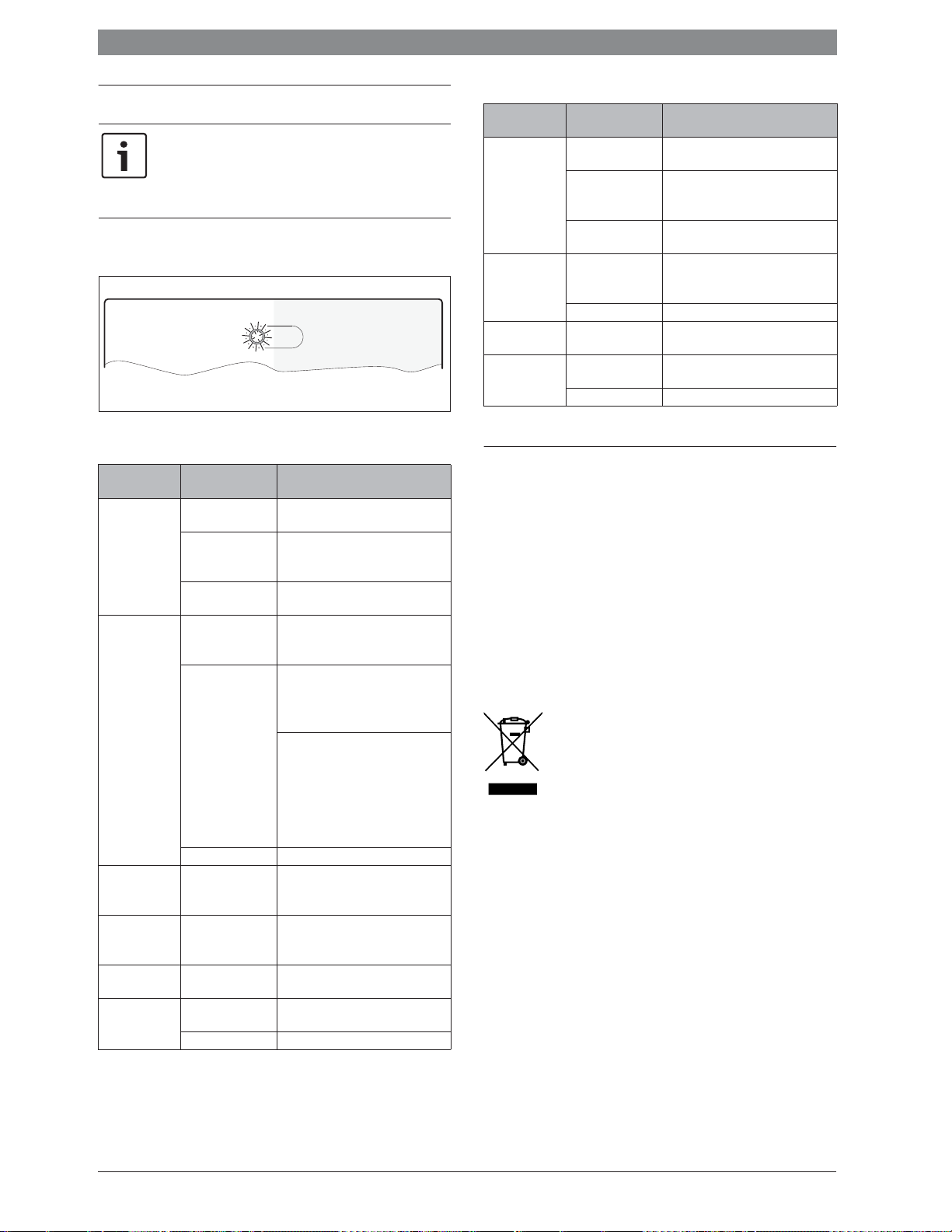
28 | Subsanación de las averías
0
1
2
3
4
5
6
7
8
9
10
5 Subsanación de las averías
Utilizar únicamente piezas de repuesto originales. Daños no
producidos por piezas de repuesto suministradas por el fabricante están excluidos de la garantía.
Cuando no se pueda reparar una avería, ponerse en contacto con el servicio técnico correspondiente.
La indicación de funcionamiento muestra el estado de funcionamiento
del módulo.
6 720 647 922-52.1O
5.1 Testigo luminoso en un módulo de cascada
individualmente instalado o de orden superior
Pantalla de funcionamiento
apagado de
forma permanente
en rojo de forma
permanente
parpadea rojo Interruptor de
parpadea verde Interruptor para
parpadea
amarillo
verde de forma
permanente
Tab. 15
Causas posibles Remedio
Alimentación de tensión interrumpida.
▶ Conectar la alimentación de ten-
sión.
Fusible defectuoso. ▶ Cambiar el fusible con fuente de
alimentación desconectada
(Æ fig. 21 en página 89).
Cortocircuito en la
conexión de BUS.
Interruptor codifica-
▶ Comprobar la conexión BUS y
reparar en caso necesario.
▶ Ajustar el interruptor codificador.
dor en posición inválida o intermedia.
Sensor de temperatura defectuoso
▶ Comprobar la sonda de tempera-
tura.
▶ En caso de no coincidir los valo-
res, cambiar la sonda
▶ Controlar la tensión de los bornes
de conexión del sensor de temperatura en el módulo.
▶ En caso de que los valores del sen-
sor estén correctos pero no coincidan los valores de tensión,
cambiar el módulo
Fallo interno ▶ Sustituir el módulo.
▶ Comprobar el interruptor de
parada en I3 está
parada.
abierto
Controlar interruptor máx. en I2
máxima potencia
está cerrado
Inicialización –
Interruptor codifica-
▶ Ajustar el interruptor codificador.
dor en 0.
No existe avería Funcionamiento normal
5.2 Testigo luminoso en un módulo o de orden inferior
Indicación de
funcionamiento
apagado de
forma permanente
Causas posibles Remedio
Alimentación de tensión interrumpida.
▶ Conectar la alimentación de ten-
sión.
Fusible defectuoso. ▶ Cambiar el fusible con fuente de
alimentación desconectada
(Æ fig. 21 en página 89)
en rojo de forma
permanente
Cortocircuito en la
conexión de BUS.
Interruptor codificador en posición invá-
▶ Comprobar la conexión BUS y
reparar en caso necesario.
▶ Ajustar el interruptor codificador.
lida o intermedia.
Fallo interno ▶ Sustituir el módulo.
parpadea
Inicialización –
amarillo
verde de forma
permanente
Interruptor codifica-
dor en 0.
▶ Ajustar el interruptor codificador.
No existe avería Funcionamiento normal
Tab. 16
6 Protección del medio ambiente/reciclaje
La protección del medio ambiente es uno de los principios empresariales del Grupo Bosch.
La calidad de los productos, la rentabilidad y la protección del medio
ambiente tienen para nosotros la misma importancia. Las leyes y normativas para la protección del medio ambiente se respetan rigurosamente.
Para proteger el medio ambiente, utilizamos las tecnologías y materiales
más adecuados, teniendo en cuenta también los aspectos económicos.
Embalaje
En cuanto al embalaje, nos implicamos en los sistemas de reutilización
específicos de cada región para garantizar un reciclaje óptimo.
Todos los materiales del embalaje son respetuosos con el medio
ambiente y reutilizables.
Aparatos usados eléctricos y electrónicos
Los aparatos eléctricos y electrónicos inservibles deben
separarse para su eliminación y reutilizarlos de acuerdo
con el medio ambiente (Directiva Europea de Residuos de
aparatos eléctricos y electrónicos).
Utilice los sistemas de restitución y colecta para la eliminación de residuos de aparatos eléctricos y electrónicos.
MC 4006 720 819 669 (2016/05)
 Loading...