

Bosch Climate 5000, MAHUP(C)-32.40, MAHUP(C)-06.07 Installation, Operation And Maintenance Manual
Modular Air Handling Unit
MAHUP(C)-06.07~ MAHUP(C)-32.40
en Installation, Operation and Maintenance Manual
8736862495 (2015/0
7)CN
Read the manual carefully prior to installation and operation the unit!
Observe the warnings in the manual!
Installation by an authourised person only!
Climate 5000

WELCOME
Distinguished users:
Thank you for choosing and using Bosch products!
For ease of use, please read the Manual carefully
and operate as per the steps as described in the
Manual. We will be with you all along. Please feel
free to contact us at the number and address on
the Warranty Card whenever you have any problems. We are ready to serve you.
Due to product improvement, the product you
have purchased may be slightly different from
those introduced in the Manual. We hereby apologize for the inconvenience we cause.
Important notice:
• Modular air handling unit is the air side of air
conditioning system for water chiller, which
requires expertise and has strict specifications
and requirements. Therefore, it must be
installed, commissioned, operated and managed (by professionally trained technical
personnel).
• The product can be used widely, except damp
environment, outdoors, the environment with
blowing dust and corrosion, and the site with
explosion hazard.
• Operating conditions:
- Power supply: 3N~/380V/50Hz
- Maximum operating pressure: ≤1.6Mpa
Our company adheres to the principle of commitment to excellence, and may not inform you of
certain improvement in specification, performance, material and structure of such products.
Sorry for the inconvenience. Please contact us for
obtaining the latest information.
Table of Contents
1 Key to symbols and safety introductions ... 3
1.1 Explanation of symbols ................................ 3
1.2 Safety information ...................... 3
1.3 Delivery, handling and storage ........... 4
1.3.1 Delivery inspection ................. 4
1.3.2 Way of transport.................... 4
1.3.3 Storage of the unit .................. 4
2 Unit introduction............................................ 6
2.1 Type introduction ....................... 6
2.2 Product introduction .................... 6
2.3 Left/ right Hand pipe connection .......... 6
2.4 Unit symbols........................... 7
2.4.1 Safety symbols..................... 7
2.4.2 Functional section and symbols ...... 7
3 Unit installation.............................................. 8
3.1 Product introduction .................... 8
3.2 Equipment assembly.................... 9
3.3 Installation and connection of air duct ......10
3.4 Installation and connection of water coil pipe 10
3.5 Installation and connection of steam coil pipe 11
3.6 Installation of siphon ....................11
3.7 Electrical wiring of motors ...............12
3.8 Electrical wiring of electrical heater .......12
3.9 Electrical wiring of humidifier .............12
4 Unit commissioning ..................................... 13
4.1 Preparations before commissioning .......13
4.2 Starting and operating ..................13
4.3 Specific Prohibitions ....................13
5 Unit maintenance ......................................... 14
5.1 Maintenance and inspection ............. 14
5.2 Storage measures for the unit long-time
shutdown .................................16
5.3 Inspection and maintenance intervals .....16
6 Fault analysis and troubleshooting............ 20
6.1 Abnormal noise ........................20
6.2 Vibration ..............................20
6.3 Overcurrent............................20
6.4 Air flow insufficient ......................21
6.5 Cooling capacity too small ...............21
6.6 Leakage ..............................21
7 Packing list ................................................... 22
8 Notes ............................................................. 23
Any figures and information in this
instruction are only for reference.
8736862495(2015/07) Climate 5000
2 | Table of contents
Climate 5000 8736862495(2015/07)
1.1 Explanation of symbols
Warnings
Keywords indicate the seriousness of the hazard
in terms of the consequences of not following the
safety instructions.
• Notice Indicates that material damage may
occur.
• Caution Indicates that minor to medium injury
may occur.
• Warning Indicates that serious injury may
occur.
• Danger Indicates possible risk to life.
Important information
Additional symbols
Tab. 1 Additional symbols
1.2 Safety information
Warnings in this document are framed
and identified by a warning triangle
which is printed on a grey background. The signal word attached
indicates the type and severity of
consequence due to nonobservance of
danger prevention measures.
Important information in cases where
there is no risk of personal injury or
material losses is identified by the symbol
shown on the left. It is bordered by
horizontal lines above and below the text.
Notice: Risk of frostbite the coil!
Please make anti-freezing preparations
and drain off the water during the winter
and in low temperature.
Symbol Definition
a step in an action sequence
a reference to a related part in the document or to other related documents
· a list entry
– a list entry (second level)
►
Key to symbols and safety instructions | 3
1 Key to symbols and safety introductions
Caution: Risk of falling!
Pay attention to the center of gravity
and weight when move in and out.
Notice:
Carry out electrical work as per relevant
electrical standards and rules for
electrical works.
Notice: Risk of loosing!
Tighten the bolt for connection and
assembling.
Notice:
Pay attention to the gravity center and
weight when moving the unit.
Notice: Risk of the fan damage!
In case of unusual event (e.g. sound,
vibration and smell), stop the unit
immediately and carry out inspection.
Notice: Risk of the motor burned!
Please use the rated volt.
Notice:
Please fix on the firm foundation.
Caution:
Do not use or inspect the machine by
non-profession operator.
Caution: Risk of scalding!
Any alteration, fixing and removal
without permission are forbidden.
Warning: Risk of scalding!
Any alteration, fixing and removal
without permission are forbidden.
Warning:
Close the access door when the unit is
running.
Caution:
Ware safety gloves and safety helmet
when inspecting. The inner part of the
unit may be very hot, so it cannot be
inspected by naked hands. Attention is
to be paid that the vane may be rotated
by wind from the duct even though the
machine is powered off.
Warning: Risk of strangulation injury!
Do not put fingers into rotating parts!
1.3 Delivery, handling and storage
Each Bosch Climate 5000 modular air handling
unit (Abbreviation: MAHU)may be delivered as an
integral whole, in segments or in separate units.
1.3.1 Delivery inspection
• Bosch Climate 5000 MAHU, although have been
experienced strict factory inspection, considering
abnormal conditions may have been occurred
during transportation, please carry out inspection
and confirmation according to following items.
• Check if piping connection ports and headers
are damaged.
• Check if coils and fins are damaged.
• Manually rotating the vane to check the abnor-
mal belt and pulley (only for the unit using belt
for driving the fan).
• Check if the vane has abnormal facts (by
manually rotating the vane).
• Check if there are obvious damages of the
outer appearance of unit body and motors.
• Verify if the product specification is conformed
to the order (please verify the nameplate).
• Check the units according to the detailed list
attached to the out-of-box form.
• Check if the bolts and nuts are loosened.
If any damages and abnormals are found, please
contact to the distributor immediately. If there is an
obvious damage, please make note on the waybill
and attach the evidence, and then carry out claim
according to the instructions on the waybill.
1.3.2 Way of transport
Prior to transport the unit, please verify there are
suitable devices and tools for handling the unit,
and they shall bear the weight of unit and all the
accessories.
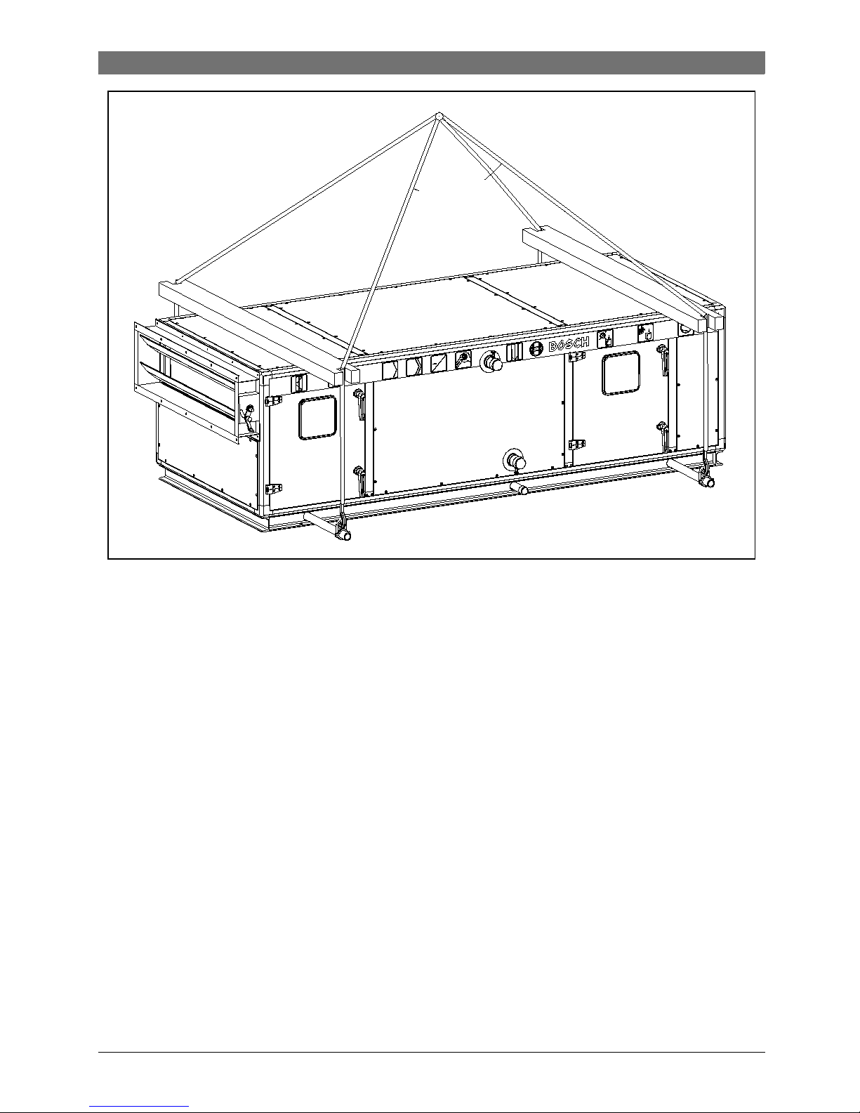
Use lifting frame for unit lifting, and length design
of lifting frame shall be capable of avoiding all
lifting loads to prevent severe damage. Each
lifting appliance shall be capable of bearing the
overall weight of the unit and maintaining sufficient weight allowance( →Page5,Fig. 1, Schematic diagram of unit lifting).
Use lifting steel pipe for unit lifting. When the
delivery weight is within 2000kg, use steel pipe
with caliber and wall thickness ≥ Φ 48×6; when
the delivery weight is within 4000kg, use steel
pipe with caliber and wall thickness ≥ Φ 48×10.
Load must be carried by base, and the suspension angle must not exceed 60°.
1.3.3 Storage of the unit
If the unit can not be installed after being delivered into the site, following protections shall be
applied:
• Put the goods on the flat plate with base down-
wards, and the shell cannot be stressed directly.
• Ensure the unit is isolated from outdoor envi-
ronment, wind and rain.
• Ensure all the orifices are equipped with
protective blind plate or closing plate.
• Put the unit away from human activity place to
avoid machinery crush.
• It is suggested to close the access door and
take off the access door key to deliver it to
responsible personnel.
• It is suggested to carry out regular inspection
for the unit during the storage.
8736862495(2015/07) Climate 5000
4 | Key to symbols and safety instructions
Danger: Beware of electric shock!
During inspection, unit must be powered off!
Danger: Beware of electric shock!
Grounding is necessary.
Notice: Risk of unit damage!
Do not put the unit on rollers!
Do not use forklift to lift the unit!
Caution: Risk of falling!
Both sides of lifting steel bar shall be
applied anti-sliding pins or fixed by pipe
clamps, to avoid slip and tilt due to
shifting of gravity center.
Key to symbols and safety instructions | 5
Climate 5000 8736862495(2015/07)
Max. 60°
Fig. 1 Schematic diagram of unit lifting

2 Unit introduction
2.1 Type introduction
Fig. 2 Type introduction drawing
2.2 Product introduction
Bosch Climate5000 modular air handling unit
manufactured by Bosch Thermal Technology(
Shandong) CO., Ltd. certified by ISO 9000
authorization, applies to strict design and manufacturing standard, meet any limits specified by
this manual, and is able to ensure the quality, and
its liability and flexibility of each type of air handling unit. The unit can be connected to water
chiller and heat pumps, and is not suitable for
other applications not specified by the manual.
The manual includes all for correct installation
and commissioning information, and operating
and maintenance instructions of the unit.
Prior to operating and maintenance of the unit,
please carefully read the manual. Any work
described in the manual including installation,
commissioning and maintenance can only be
conducted by trained and qualified professional
technicians.
Any damage and broken due to incorrect installation, operation, commissioning and maintenance,
because of failure to comply steps and instructions
specified by this manual shall be free of any
responsibilities of the manufacture.
2.3 Left/ right Hand pipe connection
( →Page 7, Fig. 3, Schematic diagram of distinguishing left and right type)
• For MAHU with Mono structure, Left or Right
Hand pipe connection is decided by judging the
relative position of Air Inlet to the Water pipe
position. (Air inlet is Left to the water pipe
position, or Right to the water pipe position).
• For MAHU with double deck or side by side
structure, Left or Right Hand pipe connection is
decided by judging the relative position of Air Inlet
to the water pipe position of the single Mono part
which contain Coil Section. See below graph.
As default, the access door is on the same side as
pipe connection.
6 | Unit introduction
8736862495(2015/07) Climate 5000
BOSCH Climate 5000
MAHU
P - 06
. 07 M
L
E
Category: Climate
Value Level: 1000~9000
Modular Air Handling Unit
P: Series Professional
C: Series Comfort
can be extended...
Type of structure:
M=Mono
S=Side by side
D=Double deck
Pipe connection:
L= Left Hand, R=Right Hand
Export(Out of CN)
Internal Width=07×Modulus(100mm)
Internal Height=06×Modulus(100mm)
Brand
Unit introduction | 7
Climate 5000 8736862495(2015/07)
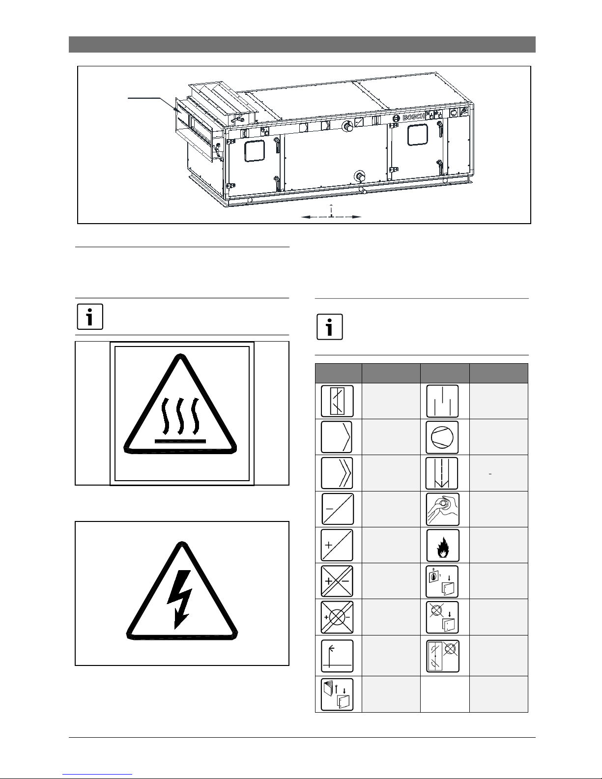
2.4 Unit symbols
2.4.1 Safety symbols
Fig. 4 Black symbol with yellow background ,
which warns high temperatureof the surface.
Fig. 5 Black symbol with yellow background,
which requires cutting off the main power before
dissembling of the machine/opening up the high
voltage electrical control box or it may cause
lethal hazard.
2.4.2 Functional section and symbols
Tab. 2 List of functional section symbols
The following symbols are attached on
each unit for the possible risks.
The following symbols are the unit
functional section or warning symbols,
the color of which is coal ash color, and
shadow of the lines is industrial gray.
高温!
HIGH TEMPERATURE!
Left
Right
Left type unit
Air inlet
Fig. 3
Schematic diagram of distinguishing left and right type
Symbols Instruction Symbols Instruction
Air damper
Muffler
Pre-filter
Fan
Medium filter
Drip eliminato
r
Cooling coil
Use a pipe
clamp when
installing coils
Heating coil
No flame
Heating and
cooling coil
Electric shock
when opening
the door
Rotary wheel
heat
exchanger
Do not open
the door when
fan operating
Humidifier
Do not start
when the air
damper is
closed
Indoor
attached
information
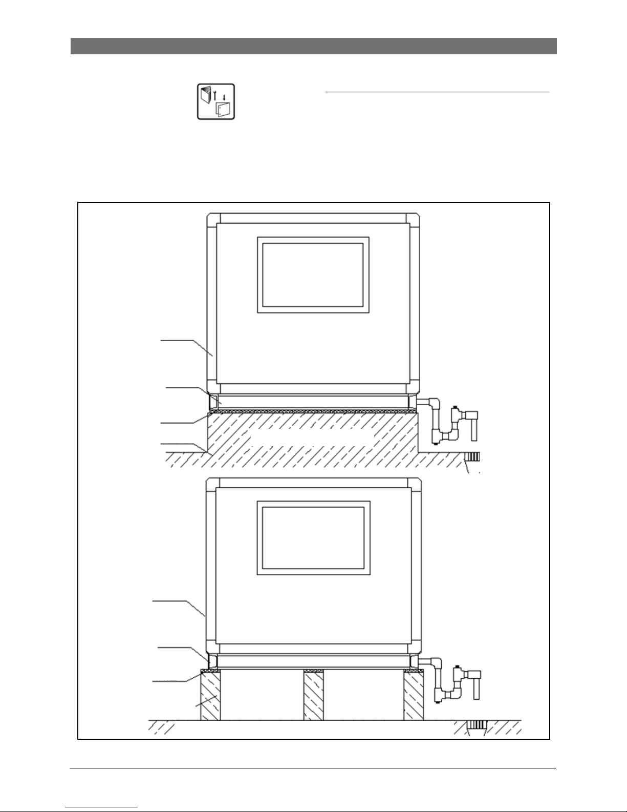
3 Unit installation
Find installation instruction , assembling
spare parts and accessories on place for storing
the documents and accessories. Before installation, transportation safety device with yellow
symbols shall be removed especially the safety
device for fan. Any abovementioned works must
be operated by professional personnel.
Fig. 6 Schematic diagram of base installation
3.1 Product introduction
• To prevent vibration and noise transmission,
anti-vibration pads shall be applied between
equipment and foundation; foundation levelness should be 1/1000. After placement, the
tolerance of entire unit in height and width shall
be controlled within 3mm. For the details of
foundation installation→Fig. 6.
8 | Unit installation
8736862495(2015/07) Climate 5000
Flat face foundation
Concrete or steel support strap footing foundation
Unit body
Unit body
Channel
Channel
Absorption gasket
Absorption gasket
Flat face foundation
Concrete or steel-frame
strip foundation
 Loading...