

Bosch MAGIC.SENS Product Manual
PRODUCT INFORMATION PI--34.65d
BDL--4998121218
A23.en / 09.02.2007
ST--FIR/ PRM1 / deh
Page1of42
MAGIC.SENS
This product information includes the
entire MAGIC.SENS -- product range.

PI -- 34.65dProduct Information MAGIC.SENS -- Product range
Page2of42
BDL--4998121218
A23.en /09.02.2007
ST--FIR/ PRM1 / deh
Table o f Contents
1. Foreword 4........................................
2. Product Description 5..............................
2.1. Configuration of the Detector 5................................
2.2. Functional Description of Sensor Technology 5...................
2.3. SystemDescriptionMAGIC.SENS...LSN 6....................
2.3.1. FeaturesMAGIC.SENS...LSN 6......................................
2.4. SystemDescriptionMAGIC.SENS...GLT 7....................
2.4.1. FeaturesMAGIC.SENS...GLT 7......................................
3. Planning Tips 8....................................
3.1. Basic Planning Guidelines 8...................................
3.2. Use on a Local Security Network (LSN) 8.......................
3.3. Use with Conventional Line Technology
(German: Gleichstrom Linientechnik, abbreviated GLT) 8..........
3.4. Use in Explosive Areas 9.....................................
3.5. Use in Areas with Elevated Radioactivity 9......................
3.6. UseinFireBarriersaccordingtoDIBt 9.........................
4. Programming 10....................................
4.1. MAGIC.SENS OTC 410 LSN 11................................
4.2. MAGIC.SENS OC 410 LSN 11.................................
4.3. MAGIC.SENS OT 400 E LSN 12................................
4.4. MAGIC.SENS O 400 E LSN 12.................................
4.5. MAGIC.SENS T 400 E LSN 13.................................
4.5.1. Sensitivity Classes according to EN 54 Part 5 13...........................
5. Technical Data: MAGIC.SENS 14.....................
5.1. Technical Data: OTC 410 / OT 400 / OC 410 LSN 14..............
5.2. Technical Data: O 400 E LSN / T 400 E LSN 15...................
5.3. Technical Data: OC 310 GLT / OT 300 GLT / O 300 GLT 16.........
5.4. Technical Data: T 300 GLT / T 300 FSA GLT 17...................
5.5. Country Approvals 18..........................................
6. Detector Base 21....................................
6.1. Detector Base MS 400 21......................................
6.2. Detector Base with Damp Room Seal MSF 400 23................
6.3. Additional Base MSC 420 23...................................
6.4. Detector Base Sirens MSS 300 / 400 / 401 24....................

PI -- 34.65dProduct Information MAGIC.SENS -- Product range
Page3of42
BDL--4998121218
A23.en /09.02.2007
ST--FIR/ PRM1 / deh
7. Accessories 25.....................................
7.1. Support Plates for Detector Zone Identification 25.................
7.1.1. Support Plate TP4 400 25..............................................
7.1.2. Support Plate TP8 400 25..............................................
7.1.3. Labels for Self--Labeling 25.............................................
7.2. Basket Guard SK 400 26.......................................
7.3. Protective Dust Cover SSK 400 26..............................
7.4. Detector Console MK 400 26...................................
7.5. Detector Heating Element MH 400 26............................
7.6. MPA External Detector Alarm Display 27.........................
8. Order Overview 29..................................
8.1. Detector Variants 29...........................................
8.2. Detectors for Special Applications 29............................
8.3. Detector Base 30.............................................
8.4. Detector Base Sirens 30.......................................
8.5. Installation Accessories 31.....................................
8.6. Detector Accessories 31.......................................
8.7. MPA External Detector Alarm Display 31.........................
9. Installation of the Detector Module 32.................
9.1. Locking the Detector Module in the Base 32......................
10. Dismounting the Detector Module 32.................
11. Maintenance and Service 33.........................
11.1. Notes for the Service: Display of Operating Data 34...............
11.2. Test Instructions for MAGIC.SENS Fire Detector 36...............
11.7. Coding of the Detector Types 38................................
12. Repair 38...........................................
13. Disposal 38.........................................
14. Additional Documentation 38........................
14.1. Service Accessories 39........................................
15. Table of Abbreviations 40............................
16. Notes 41...........................................

PI -- 34.65dProduct Information MAGIC.SENS -- Product range
Page4of42
BDL--4998121218
A23.en /09.02.2007
ST--FIR/ PRM1 / deh
1. Foreword
The MAGIC .SENS fire detector series combines standard detection procedures such
as scattered light measurement and temperature measurement in their highest stage
of expansion with gas measurement technology.
Here, the signalsof scattered lightsensors, temperature sensors, and gas sensors are
processed with the help of modern signal--processing procedures.
Thus security against deceptive alarms is increased significantly and detection time
is reduced in comparison to the fire detectors available on the market today.
Thanks to the higher information content of the multisensor detectors, the use of
detectors is also possible in environments where pure smoke detectors cannot be
used.
The detectors are available in thefollowing stages of
expansion:
D Combined optical, thermal, gas--sensitive smoke detectors
D Combined optical, thermal smoke detectors
D Optical smoke detectors
D Thermal detectors
D Combined optical, gas--sensitive detectors
The line technology variants
are:
D LSN (Local SecurityNetwork)
D GLT (Gleichstrom (conventional line)technology)
The cooperation of engineers and designers created the timeless, innovative design
of this detector, which integrates pleasantly into the ceiling.
With this design it is possible to reconcile the contradictory goals of a generous
installation space and a small detector.
The placement of the individual display on the detector tip is the first externally--visible
characteristic of the installation--friendly development concept.
The form--stable and robust detector base must no longer be aligned using the
position--independent position of the individual display.
It is suitable for surface and concealed mounting and provides separate mounting
points for dropped ceiling / recessed sockets.
In addition, it fits all common bore patterns.
For surface mounting, the cable may be fed through on the side.
The integrated strain relief for false floor cables prevents cables from being pulled out
of the terminal after installation.
The terminals are easily accessible, a retainer for the end resistance is integrated.
Cables up to 2.5 mm in diameter2canbeused.
It can be expanded with a damp room seal so that with one base, all installation
requirements can be met.
PI -- 34.65dProduct Information MAGIC.SENS -- Product range
Page5of42
BDL--4998121218
A23.en /09.02.2007
ST--FIR/ PRM1 / deh
2. Product Description
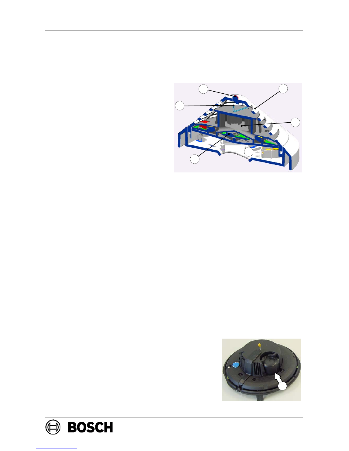
2.1. C onfiguration of the Detector
1 = Smoke measuring chamber
(Optical sensor)
2=Thermal sensor
3=Chemical sensor
(covered on the
cross--section)
4 = Individual display
5 = PC board with evaluation
electronics
6 = Base MS 400
2.2. Functional Description of Sensor Technology
2.2.1. Optical sensor (smoke detector)
The optical sensor works according to the scattered light method.
A light diode sends light into the measuring chamber; this light is absorbed by the
labyrinth structure. In case of fire, smoke enters the measuring chamber. The light is
scattered by the smoke particles and hits the photo diodes that transform the quantity
of light into a proportional electrical signal.
2.2.2. Thermal Sensor (temperature detector)
A thermistor (2) arranged on a resistance network serves as a thermal sensor on which an
analog--digital converter measures the temperature--dependent voltage at cyclical intervals.
Depending on the detector class set, the temperature measurement unit switches to
an alarm state if the maximum temperature exceeds 54
°Cor69°C
(thermo--maximum) or a defined temperature increase within a particular time
(thermo--differential).
2.2.3. Chemical sensor (CO gas sensor)
The main function of the gas sensor (3) is to detect
carbon monoxide (CO) generated as a result of a fire,
but it will also detect h ydrogen (H) and nitrous
monoxide (NO).
The underlying measurement principle is CO
oxidation and the measurable current that it creates.
The sensor signal value is proportional to the
concentration of gas.
The gas sensor delivers additional information to
effectively suppress deceptive values.
6
4
5
2
1
3
3

PI -- 34.65dProduct Information MAGIC.SENS -- Product range
Page6of42
BDL--4998121218
A23.en /09.02.2007
ST--FIR/ PRM1 / deh
2.3. System Description MAGIC.SENS ...LSN
Up to three detection principles are integrated into the multisensor detector
MAGIC.SENS . . . 400/410 LSN:
1. Optical (for smoke)
2. Thermal (for heat) OTC, OC, OT, O, T
3. Chemical (for gas)
The individual sensors can be programmed via the LSN network manually or
time--controlled. All sensor signals are evaluated continually by the internal signal
analysis electronics and are linked with each other. By linking the sensors (combined
detectors), the detector can also be used in places where the work carried out gives
rise to light smoke, steam or dust. If with the OC, OT, O, and T detectors a signal
combination fits the selected identifier for the area of operation, an alarm is triggered
automatically.
2.3.1.FeaturesMAGIC.SENS...LSN
D Active self--monitoring of the sensors, with display on the fire panel:
-- Display for defined sensor faults (life--zero monitoring),
-- Stepless display of the degree of contamination (only in service),
-- Fault indication with heavy contamination (instead of false alarm).
D Active adjustment of the threshold (drift compensation) if the optical sensor
becomes contaminated.
D Active adjustment of the threshold (drift compensation) of the chemical sensor.
D The EMVsecurity is, with 30V/m in the range 1--1000MHz and with 40V/m in the
cellular frequency ranges 415--466MHz and 890--960MHz, significantly higher than
that required by VdS 2110 (VdS Schadenverhütung GmbH).
D Thanks to integrated isolators, the LSN ring will continue to function in case of
wire breakage or short--circuit of a detector.
D Detector individual identification on the fire panel in case of alarm. Alarm
display on the detector with a blinking red LED.
D Programmable, that is, can be adjusted to the area of operation.
D Increased detection and false alarm security thanks to evaluation of the temporal
behavior of fire and disturbance variables.
D Manual or time--controlled switch--off of individual sensors for adjustment to
extreme disturbance variables.
D Activation of a remote external detector alarm display is possible.
D Variable mechanical removal safeguard (can be activated/deactivated).
D Dust-- resistant labyrinth and cap construction.
D Can be connected to the LSN – fire panel BZ 500 / universal European central unit
UEZ 2000 / universal danger detection system UGM 2020 and to other central units
or their receiver components with identical connection conditions.
D Depending on the central unit, using the WinPara program (Version 4.53 or higher)
it is possible to read out the serial number, degree of contamination (for the O unit),
operating hours, and current analog values for each configured detector.

PI -- 34.65dProduct Information MAGIC.SENS -- Product range
Page7of42
BDL--4998121218
A23.en /09.02.2007
ST--FIR/ PRM1 / deh
2.4. System Description MAGIC.SENS ...GLT
Up to two of the following detection principles are integrated into the m ultisensor
detector MAGIC.SENS . . . 300/310 GLT:
1. Optical (for smoke)
2. Thermal (for heat) OC, OT, O, T
3. Chemical (for gas)
All sensor signals are evaluated continually by the internal signal analysis electronics
and are linked with each other. If a signal combination fits into the detector’s
programmed identifier field, the alarm is triggered automatically.
By linking the sensors (combined detectors), the detector can also be used in places
where the work carried out gives rise to light smoke, steam or dust.
2.4.1.FeaturesMAGIC.SENS...GLT
D Active adjustment of the threshold (drift compensation) if the optical sensor
becomes contaminated.
D Active adjustment of the threshold (drift compensation) of the chemical sensor.
D The EMVsecurity is, with 30V/m in the range 1--1000MHz and with 40V/m in the
cellular frequency ranges 415--466MHz and 890--960MHz, significantly higher than
that required by VdS 2110 (VdS Schadenverhütung GmbH).
D Activation of a remote external detector alarm display is possible.
D Variable mechanical removal safeguard (can be activated/deactivated).
D Dust-- resistant labyrinth and cap construction.
D Can be connected to the GLT fire panels B Z 1012 / 1024 / 1060, universal European
central unit UEZ 1000, universal danger detection system UGM 2020 and to other
central units or their receiver components with identical connection conditions.

PI -- 34.65dProduct Information MAGIC.SENS -- Product range
Page8of42
BDL--4998121218
A23.en /09.02.2007
ST--FIR/ PRM1 / deh
3. Planning Notes
MAGIC.SENS fire detectors are not intended for
external use!
3.1. Basic Planning Specifications
D The planning of multisensor fire detectors (combination detectors) occurs
according to the guidelines for optical detectors until an independent guideline has
been worked out with the VdS.
D The types OTC, OC and OT are planned according to the guidelines for optical
detectors if they are operated as optical detectors or combined detectors; see
DIN VDE 0833 Part 2 and VDS 2095,
-- maximum monitoring area 120m
2
,
-- installation height up to 16m.
D If the occasional switching--off of the optical unit (scattered light sensor) is
desired, the planning must occur according to the guidelines for heat detectors;
see DIN VDE 0833 Part 2 and VDS 2095,
-- minimum monitoring area 40m
2
,
-- installation height maximum 7.5m for the T 400 E LSN or OT 400 E LSN
,
-- installation height maximum 6m for the T 300 GLT or OT 300 GLT.
D Maximum cable length: 1000m, for J--Y(St) Y n x 2 x 0.6 / 0.8.
D Maximum permissible air speed: 20m/s.
D When planning for fire barriers according to DIBt, the following must be taken
into account:
-- T 400 E LSN must be programmed according to class A1R,
-- the characteristic curve of the T 300 / FSA also corresponds to the A1R class.
3.2. Use on a Local Security Network (LSN)
On the LSN, up to 127 detectors can be operated in the following operating modes
depending on the loop or stub:
Operating mode
Detector type combined only optical onl y thermo--maximum only thermo--differential
OTC 410 LSN x x x x
OC 410 LSN x x -- --
OT 400 E LSN x x x x
O 400 E LSN -- x -- --
T 400 E LSN -- -- x x
3.3. Use with Conventional Line Technology
(German: Gleichstrom Linientechnik, abbreviated (GLT)
The GLT technology permits the connection of up to detectors to a primary line.

PI -- 34.65dProduct Information MAGIC.SENS -- Product range
Page9of42
BDL--4998121218
A23.en /09.02.2007
ST--FIR/ PRM1 / deh
3.4. Use in Explosive Areas
All MAGIC.SENS detectortypes conformto the device category3G,
gas group IIB, and temperature class T6, in accordance with the
European guideline 94/9/EG (ATEX). Thus the detectors may be
used in Zone 2 areas where there is danger of explosion!
Limiting values:
D Detectors may only be operated with central units whose line output is
energy--limited according to EN 50021.
. This is a given for all Bosch fire panels.
D The line voltage (U
max
) may not exceed 33V!
D The maximum current (I
max
) must be limited to 130mA!
D The auxiliary voltage may not be fed through the ex area!
Fire detector cable:
D Only fire detector cables t h at conform to DIN VDE 0814 may be used.
D The entire cable capacity (C
max
) may not exceed 1mF!
D The entire cable inductivity (L
max
) may not exceed 0.01H!
. The cable type J--Y(ST)Y08, according to DIN VDE 0815 (Table 10),
has a capacity of 120ηF with a length of 1000m.
Detector heating element:
D The use of a detector heating element (MH 400) is not permissible!
3.5. Use in Areas with Elevated Radioactivity
D There are three LSN detector types available especially for use in areas with
elevated radioactivity, such as in nuclear power plants:
-- Magic.Sens OT 400 LSN KKW
-- Magic.Sens O 400 LSN KKW
-- Magic.Sens T 400 LSN KKW
3.6. Use in Fire Barriers according to DIBt
D There are four detector types available for use in fire barriers according to the
guideline of the DIBt (German Institute for Building Technology):
-- Magic.Sens O 400 LSN KKW
-- Magic.Sens T 400 LSN KKW
-- Magic.Sens O 300 GLT
-- Magic.Sens T 300 / FSA GLT

PI -- 34.65dProduct Information MAGIC.SENS -- Product range
Page 10 of 42
BDL--4
998121218
A23.en /0
9.02.2007
ST--F
IR/ PRM1 / deh
4. Programming
Programming is setting a LSN detector to the desired operating mode.
Pro
gramming is carried out with the>WinPara< software using a PC or laptop connected
to t
he fire panel.
All sensor signals are analyzed continually by the internal evaluation electronics and
are linked with each other via an inbuilt microprocessor.
The d
etectors OTC 410 LSN OC 410 LSN and OT 400 E LSN are programmed by
specifying the o
peration location (e.g. computer room, office, large kitchen).
The sele
ction of the operation location determines the optimal characteristic diagram
for fire a
nd disturbance variable evaluation.
With low sensitivity of the o
ptical sensor in the OTC 410 LSN, the detector onlytriggers
if s
moke and also an increase of the CO concentration or the temperature is detected.
With the ty
pes OTC 410 LSN and OT 400 E LSN, the operating mode can be changed.
Th
at is, individual sensors can be switched off:
-- Sw
itch to optical (sensitivity O unit = low, T unit = switched off)
-- Sw
itchover to thermo--differential (sensitivity T unit = A2R, O unit = switched off)
-- Sw
itchover to thermo--maximum (sensitivity T unit = A2S, O unit = switched off)
With p
urely optical detectors O 400 E LSN, the sensitivity of the optical sensors can
be s
et on 3 levels. Depending on the operation location, the optical sensor in the
detector is th
us adjusted to the environmental conditions.
For fire re
cognition, the optical detector uses the temporal behavior of the firevariables
that deviates significantly from the temporal behavior of disturbance variables and
also f
rom the time behavior of a detector test with aerosol. Depending on the sensitivity
set, t
herefore there are also different trigger times when testing with a test aerosol,
outside of main
tenance operation (10s to max 60s).
The thermal detector T 400 E LSN is programmed by taking into account the ambient
temperature a
nd installation height with the selection of the sensitivity class.
Pro
gramming of the optical, thermal, and chemical detector and the linking of all detectors
via al
gorithms significantly increases the detection ability and security against false alarms.

PI -- 34.65dProduct Information MAGIC.SENS -- Product range
Page 11 of 42
BDL--4998121218
A23.en /09.02.2007
ST--FIR/ PRM1 / deh
4.1. MAGIC.SENS OTC 410 LSN
Operation locations that can be selected
Sensitivity
Operationlocationsthatcanbeselected
in the >WinPara< programming software
D
etector type
T
max
--unit O--unit C--unit
Theaters / Concert Halls combined
O+T
max+Tdiff
+C
high (A2) medium high
Warehouse with vehicle traffic combined
O+T
max+Tdiff
+C
low (B) low* low
Office (smokers) / Restaurant /
Waiting room / Conference room
combined
O+T
max+Tdiff
+C
high (A2) low* low
Conference room / Waiting room
/ Exhibition hall
combined
O+T
max+Tdiff
+C
high (A2) low* medium
Office (no traffic) combined
O+T
max+Tdiff
+C
high (A2) high high
School / Kindergarten combined
O+T
max+Tdiff
+C
high (A2) medium high
Garage combined
O+T
max+Tdiff
+C
high (A2) low* low
Kitchen / Casino /
Restaurant during active operation
combined
O+T
max
+C
low (B) low* low
Production Facilities combined
O+T
max+Tdiff
+C
low (B) low* medium
Computer room combined
O+T
max+Tdiff
+C
high (A2) high high
High--board warehouse without vehicle
traffic with combustion motors.
combined
O+T
max+Tdiff
+C
low (B) high high
Office (daily operation) combined
O+T
max+Tdiff
+C
low (B) medium high
*With low sensitivity of the optical sensor, the detector only triggers if smoke and also an increase of
the CO concentration or the temperature is detected.
4.2. MAGIC.SENS OC 410 LSN
Operation locations that can be selected in the
Sensitivity
Operationlocationsthatcanbeselectedinth
e
>WinPara< programming software
D
etector type
O--unit C--unit
Theaters / Concert Halls combined (O + C) medium
Warehouse with vehicle traffic combined (O + C) low
ally
n.
Office (smokers) / Waiting room / Restaurant / Conference
room
combined (O + C) low
ys equ
a
locatio
n
Conference room / Waiting room / Exhibition hall combined (O + C) low
lwa
y
ion l
o
Office (no traffic) combined (O + C) high
is
a
erat
i
School / Kindergarten combined (O + C) medium
unit
op
e
Garage combined (O + C) low
eC
fth
e
Kitchen / Casino / Restaurant during operation combined (O + C) low
of th
e
ss o
f
Production Facilities combined (O + C) low
ity
o
rdle
s
Computer room combined (O + C) high
siti
v
rega
r
High--board warehouse without vehicle traffic with
combustion motors
combined (O + C) high
he se
n
high, r
Office (daily operation) combined (O + C) medium
T

PI -- 34.65dProduct Information MAGIC.SENS -- Product range
Page 12 of 42
BDL--4998121218
A23.en /09.02.2007
ST--FIR/ PRM1 / deh
4.3. MAGIC.SENS OT 400 E LSN
Sensitivity
Operation locations that can be selected in the
>WinPara< programming software
Detector type
T
max
--uni
t
O--unit
Theaters / Concert Halls combined
O+T
max+Tdiff
high (A2) mediu
m
Warehouse with vehicle traffic combined
O+T
max+Tdiff
low (B) low
Office (smokers) / Waiting room / Restaurant /
Conference room
combined
O+T
max+Tdiff
high (A2) low
Conference room / Waiting room / Exhibition hall combined
O+T
max+Tdiff
high (A2) low
Office (no traffic) combined
O+T
max+Tdiff
high (A2) high
School / Kindergarten combined
O+T
max+Tdiff
high (A2) mediu
m
Garage T
max+Tdiff
high (A2) --
Kitchen / Casino / Restaurant (during operation) T
max
low (B) --
Production Facilities combined
O+T
max+Tdiff
low (B) low
Computer room combined
O+T
max+Tdiff
high (A2) high
High--board warehouse without vehicle traffic with
combustion motors
combined
O+T
max+Tdiff
low (B) high
Office (daily operation) combined
O+T
max+Tdiff
low (B) mediu
m
4.4. MAGIC.SENS O 400 E LSN
Operation location and recommended settingin the Sensitivit
y
Operationlocationandrecommendedsettinginthe
>WinPara< programming software
Sensitivity
O--unit
Theaters / Concert Halls medium
Warehouse with vehicle traffic low
Office (smokers) / Waiting room / Restaurant / Conference room low
Conference room / Waiting room / Exhibition hall low
Office (no traffic) high
School / Kindergarten medium
Production Facilities low
Computer room high
High--board warehouse without vehicle traffic with combustion motors high
Office (daily operation) medium
For fire detection, the purely optical detector also evaluates the time
behavior of the fire characteristics that dif f ers si gnificantl y from the time
behavior of characteristics during a detector test. Depending on the
sensitivity set, therefore there are also different trigger times when testing
with a test aerosol, outside of maintenance operation (10s to max 60s).

PI -- 34.65dProduct Information MAGIC.SENS -- Product range
Page 13 of 42
BDL--4998121218
A23.en /09.02.2007
ST--FIR/ PRM1 / deh
4.5. MAGIC.SENS T 400 E LSN
Selectable sensitivity classes in the >WinPara< programming software
§A2R Typical application temperature: 25_C, T
max+Tdiff,
height up to 6m
A2S Typical application temperature: 25_C, only T
max,
height up to 6m
A1R Typical application temperature: 25_C, T
max+Tdiff,
height 6--7.5m
A1 Typical application temperature: 25_C, only T
max.,
height 6--7.5m
BR Typical application temperature: 40_C, T
max+Tdiff.,
height up to 6m
BS Typical application temperature: 40_C, only T
max.,
height up to 6m
§ = basic setting in the >WinPara<programming software
. During installation for automatic door control according to DIBt, the detector
must be programmed according to the class A1R!
4.5.1. Sensitivity classes according to EN 54 Part 5
The MAGIC.SENS T 400 E LSN gives you the opportunity, according to the
programming, to specify one of the six sensitivity classes listed above.
In the sensitivity classes A1, A2S and BS, the MAGIC.SENS T 400 E LSN is operated
as a pure thermo--maximum detector.
Here in the class A2S the detector does not activate under 54_C and in class BS not
under 69_C.
The sensitivity classes A2S and BS are therefore especially suitable for applications
where over a longer period, higher temperature rates -- of--rise occur, e.g. in kitchens
or boiler rooms.
The sensitivity classes A1R, A2R and BR mean that in addition to the thermomax
unit, the thermodifferential unit is also active.
These sensitivity classes are especially well--suited for use in unheated buildings where
the ambient temperature can vary greatly but temperature rates--of--rise do not last long.
With the thermodifferential unit, the detectors in classes A1R/A2R activate at
T< 54°C and in class BR at T< 69°C; see table page 15.
The selection of the sensitivity class also depends on the installation height of the
detector (see table above).
For the highest security against false alarms, withroom heights below 6 m, the classes
A1 and A1R should not be selected, although this is allowed in principle. Furthermore,
the expected application temperature must be taken into consideration.
 Loading...