

Bosch MADI Card Plus User Manual
MADI Card Plus
Multichannel Audio Digital Interface Card
User Manual
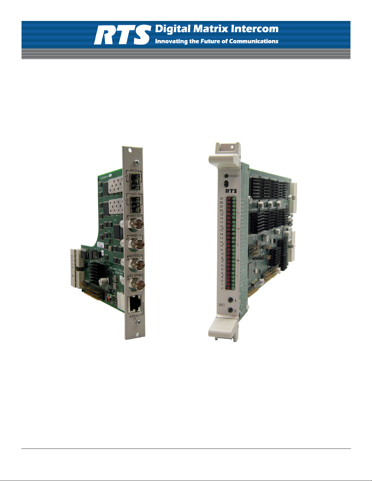
MADI
Back Card
93507896000 Rev B 08/2010
MADI
Front Card

PROPRIETARY NOTICE
The product information and design disclosed herein were originated by
and are the property of Bosch Security Systems, Inc. Bosch reserves all
patent, proprietary design, manufacturing, reproduction, use and sales
rights thereto, and to any article disclosed therein, except to the extent
rights are expressly granted to others.
COPYRIGHT NOTICE
Copyright 2010 by Bosch Security Systems, Inc. All rights reserved.
Reproduction, in whole or in part, without prior written permission from
Bosch is prohibited.
WARRANTY AND SERVICE INFORMATION
For warranty and service information, refer to the appropriate web site
below:
RTS ....................................................... www.rtsintercoms.com/warranty
RTSTW............................................................. www.rtstw.com/warranty
AudioCom......................................... www.telexaudiocom.com/warranty
RadioCom .......................................... www.telexradiocom.com/warranty
Headsets ........................................ www.intercomheadsets.com/warranty
CUSTOMER SUPPORT
Technical questions should be directed to:
Customer Service Department
Bosch Security Systems, Inc.
12000 Portland Avenue South
Burnsville, MN 55337 USA
Telephone: 877-863-4169
Fax: 800-323-0498
Info@rtsintercoms.com
Technical Questions EMEA
Bosch Security Systems Technical Support EMEA
http://www.rtsintercoms.com/contact_main.php

AVAILABLE MADI CARD OPTIONS
MADI-16 Card .........................................................................................................................................................................F01U169843
MADI-32 Card .........................................................................................................................................................................F01U169844
MADI-48 Card .........................................................................................................................................................................F01U169845
MADI-64 Card .........................................................................................................................................................................F01U169846
MADI-16 to 32 Upgrade ..........................................................................................................................................................F01U169847
MADI-16 to 48 Upgrade ..........................................................................................................................................................F01U169848
MADI-16 to 64 Upgrade ..........................................................................................................................................................F01U169849
MADI-32 to 48 Upgrade ..........................................................................................................................................................F01U169850
MADI-32 to 64 Upgrade ..........................................................................................................................................................F01U169851
MADI-48 to 64 Upgrade ..........................................................................................................................................................F01U169852


Table
of
Contents
INTRODUCTION ................................................................................................................................... 3
Features ................................................................................................................................................................ 3
Reference Views .................................................................................................................................................. 4
Specifications ...................................................................................................................................................... 6
Connection Pin Outs ............................................................................................................................................ 7
RJ-45 Pin Outs ..................................................................................................................................................................7
Front Card DIP Switch ........................................................................................................................................ 8
Back Card DIP Switch ......................................................................................................................................... 9
System Configuration Schemes ......................................................................................................................... 10
Word Clock Configuration .............................................................................................................................................10
Fiber Configuration .........................................................................................................................................................11
Coaxial Configuration .....................................................................................................................................................11
TV Sync Configuration ...................................................................................................................................................12
Serial Pass-Through Configuration .................................................................................................................................12
Trunking Configuration ..................................................................................................................................................13
INSTALLATION ................................................................................................................................... 15
Requirements ..................................................................................................................................................... 15
How to Install .................................................................................................................................................... 15
Card Installation ..............................................................................................................................................................15
Cable the System .............................................................................................................................................................16
Configure your MADI 16 Plus Card ...............................................................................................................................16
WINDOW DESCRIPTIONS ................................................................................................................. 17
MADI Card Configuration Window ................................................................................................................. 17
Slot Display Column .......................................................................................................................................................17
Description Display Column ...........................................................................................................................................18
Ports Display Column (1) ...............................................................................................................................................18
Ports Display Column (2) ...............................................................................................................................................18
Type Display Column .....................................................................................................................................................18
Reference Clock Drop Down Column ............................................................................................................................18
Sample Rate Drop Down Column ..................................................................................................................................19
# of Channels Drop Down Column ................................................................................................................................19
Link Mode Drop Down Column .....................................................................................................................................19
Baud Rate Drop Down Column ......................................................................................................................................19
Show MADI Cards Only Check Box ..............................................................................................................................19
MADI Channel Mapping Window .................................................................................................................... 20
Card Slot Group Box 20

Card Slot Drop Down List ..............................................................................................................................................20
Show MADI Cards Only Check Box ..............................................................................................................................20
Entry Display Column ....................................................................................................................................................20
Port Display Column .......................................................................................................................................................20
Alpha Display Column ...................................................................................................................................................21
MADI Channel Drop Down Column ..............................................................................................................................21
Muted? Check Box Column ............................................................................................................................................21
Show Unavailable Channels Check Box ........................................................................................................................21
MADI Card Status Window ..............................................................................................................................22
Slot Display Column .......................................................................................................................................................22
Description Display Column ...........................................................................................................................................22
Ports Display Column (1) ...............................................................................................................................................22
Ports Display Column (2) ...............................................................................................................................................22
Type Display Column .....................................................................................................................................................22
Active Link Display Column ..........................................................................................................................................23
Backup Link Display Column ........................................................................................................................................23
Status Display Column ...................................................................................................................................................23
Pass-Through Display Column .......................................................................................................................................23
MADI to Serial Display Column ....................................................................................................................................23
Serial to MADI Display Column ....................................................................................................................................23
CONFIGURATION .............................................................................................................................. 25
Channel Allocation Scheme ...............................................................................................................................25
Base 8 ..............................................................................................................................................................................25
Base 16 ............................................................................................................................................................................26
Reference Clock .................................................................................................................................................28
Sample Rate .......................................................................................................................................................29
Channel Size ......................................................................................................................................................30
Channel Mapping ...............................................................................................................................................31
Merge Channels .................................................................................................................................................35
Download Firmware ..........................................................................................................................................36
Download License File to MADI Card ..............................................................................................................37
PORT ALLOCATION TABLE ............................................................................................................. 39
Introduction ........................................................................................................................................................39
Requirements: .................................................................................................................................................................39
Port Allocation Table Window ..........................................................................................................................40
Slot Column ....................................................................................................................................................................40
Type Column ..................................................................................................................................................................40
Allocated Column ...........................................................................................................................................................41
Ports Columns (4) ...........................................................................................................................................................42
Warning Column .............................................................................................................................................................42
Warning Field .................................................................................................................................................................43
Apply Button ...................................................................................................................................................................43
Test Button ......................................................................................................................................................................43
Cancel Button ..................................................................................................................................................................43

List
of
Figures
FIGURE 1. MADI 16 Plus Back Card Reference View .................................................................................... 5
FIGURE 2. Front Card DIP Switch Location .................................................................................................... 8
FIGURE 3. Back Card DIP Switch Location ..................................................................................................... 9
FIGURE 4. 3 Card Word Clock Daisy Chain Wiring ...................................................................................... 10
FIGURE 5. 3 Card Word Clock Hub Wiring ................................................................................................... 10
FIGURE 6. 3 Card Fiber Module A and Module B Wiring .............................................................................11
FIGURE 7. 3 Card Coaxial Wiring .................................................................................................................. 11
FIGURE 8. 3 Card TV Sync Hub Wiring ........................................................................................................ 12
FIGURE 9. Serial Pass-Through Wiring .......................................................................................................... 12
FIGURE 10. MADI-16 Plus – Trunking Configuration ....................................................................................13
FIGURE 11. MADI Card Configuration Page ................................................................................................... 17
FIGURE 12. Edit Alpha/Description Window .................................................................................................. 18
FIGURE 13. MADI Channel Mapping Window ...............................................................................................20
FIGURE 14. MADI Card Status Window ......................................................................................................... 22
FIGURE 15. Base 16 Port Numbering Scheme Example ..................................................................................26
FIGURE 16. Base 8 Channel Number Scheme Example ..................................................................................26
FIGURE 17. Base Sixteen Check Box ............................................................................................................... 27
FIGURE 18. Reference Drop Down Menu ........................................................................................................ 28
FIGURE 19. Sample Rate Drop Down Menu .................................................................................................... 29
FIGURE 20. Channels Drop Down Menu ......................................................................................................... 30
FIGURE 21. Channel Mapping Page ................................................................................................................. 31
FIGURE 22. MADI Device Channel Menu ....................................................................................................... 32
FIGURE 23. Channel Mapping Page ................................................................................................................. 33
FIGURE 24. MADI Device Channel Ranges ....................................................................................................34
FIGURE 25. MADI Merge Example ................................................................................................................. 35
FIGURE 26. I/O Card Version Information Window ........................................................................................ 36
FIGURE 27. Download Device Firmware Window .......................................................................................... 36
FIGURE 28. Success Message ........................................................................................................................... 37
FIGURE 29. Download License Popup Menu ................................................................................................... 37
FIGURE 30. Download License File Window ..................................................................................................38
FIGURE 31. Port Allocation Table Window ..................................................................................................... 40
FIGURE 32. Type Column Options ................................................................................................................... 40
FIGURE 33. Allocated Menu Options ............................................................................................................... 41
FIGURE 34. Ports Column Options ................................................................................................................... 42
FIGURE 35. Warning Field ............................................................................................................................... 43


CHAPTER 1
Introduction
The MADI 16 Plus card (9000-7896-000) expands the ADAM system configuration capabilities by utilizing
MADI (Multi-channel Audio Digital Interface) technology to connect any AES-10 compliant device over coaxial or fiber
connections at sampling rates of 44.1kHz and 48kHz. The MADI is a point-to-point configuration which provides for little or
no delay in the transmission of audio across lines.
The MADI 16 Plus is fully scalable, allowing 16 to 64 channels of audio in and out. It supports all standard, hot-swappable and
configurable features through RTS’ AZedit configuration software.
The MADI 16 Plus card allows audio connections between intercom frames and has an RS-232/-485 serial connection for
serial pass-thru port connections. It also offers a fiber connection that provides a single mode option with a range up to 9.32
miles (15km) between ADAM frames.
Features
Installation - The MADI 16 Plus is hot-swappable and installs in any available slot in an ADAM Intercom
System. It has an RJ-45 connection for an RS-232 or RS-485 pass-thru serial port.
Scalability - Provides 16 to 64 individually addressable audio channels. Each initial MADI card has 16
channels, with additional channels available for purchase in increments of 16.
Word Clock and TV
Interface -
Fiber Optic Mode - The MADI 16 Plus provides a single mode of operation providing up to 9.32 miles or 15km
Trunk Capable - The MADI 16 Plus supports supplemental data control for use with the RTS’ Intelligent
AZedit Configuration - Users are able to configure the audio parameters of each MADI channel in AZedit.
Pass-Thru Serial Port - Provides a virtual serial connection over a MADI connection using an RJ-45 connection.
An external reference for the MADI 16 Plus, the word clock interface allows seamless
synchronization of many different audio sources.
between ADAM systems.
Trunking.
3
Reference Views
Reference Views
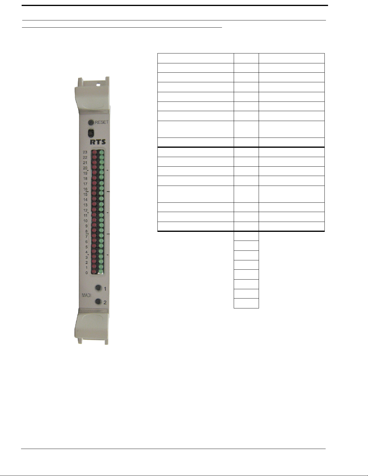
TABL E 1 . MADI 16 Plus Front Card LED Reference View
Red LEDs LED # Green LEDs
TXing on Control Bus 23 RXing on Control Bus
22 Processing RX Message
Link Fault – Fiber A 21 Using Fiber A
Link Fault – Fiber B 20 Using Fiber B
Link Fault – Coax 19 Using Coax
PLL Unlocked 18 PLL Locked
Invalid/Error Back Card 17
Driving Clock 16 Clock Good
15
14
13
Pass-Through: RS-485 12 Pass-Through: RS-232
Pass-Through: MADI to
Serial Data Transferred
11
10 Ctrl Bus: RX Byte
9 Ctrl Bus: RX Message
8 Acquired Ctrl Bus
7
6
5
4
3
2
1
0
Valid Back Card/FPGA
Booted
Pass-Through: Serial to
MADI Data Transferred
4
Reference Views
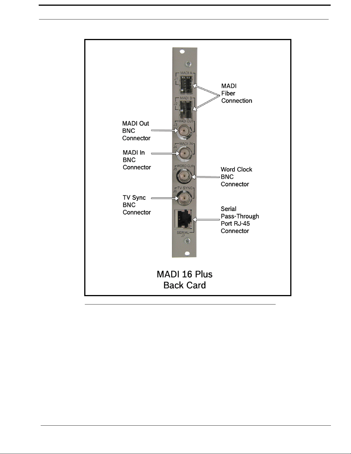
FIGURE 1. MADI 16 Plus Back Card Reference View
5

Specifications
Specifications
Power
Input Power
5.2Amps @ 5V (MADI Front/Back Card
Combined)
Power Consumption
26W
Audio Performance
THD+N at 1KHz, 0.4%
Frequency Response
within ±1dB from 20Hz - 20kHz
Channel Support
56 Channels
64 Channels
Connections
Type: Word Clock BNC Connector
Sample Rate
48KHz
44.1KHz
Type: TV Sync BNC Connector
TV Signal Input
1Volt p-p
Type: Fiber Optic
LC Connector
Single Mode
Distance: 15km (9.32 miles)
Type: Serial Pass-Through Port
RS232/485 using an RJ-45 connector
Environmental
Weight:
NOTE: The fiber optic transceivers provide Class 1 eye
safety by design and do not emit accessible
laser radiation levels in excess of the
acceptable emission limit (AEL) within the
inherent design or intended use of the laser.
Exempt, do not pose a hazard under normal
operating conditions. These low powered lasers
are incapable of producing injury when used as
designed and intended and are exempt from
engineering and administrative controls. A
Class 1 laser could potentially have an
embedded higher class inside of it. During
service procedures with service panels
removed and interlocks bypassed, it might be
necessary to comply with higher class laser
control measures during the service / repair
procedure. Class 1 includes lasers that were
formerly classified as Class 2a.
a
a
Front Card: .88lbs (.40kg)
Back Card: .42lbs (.19kg)
Temperature
Operating
0°C to 50°C (32°F to 122°F)
Storage
-40°C to 70°C (-40°F to 158°F)
a. Use RG59/U 75 Ohm cable type for best results
6

Connection Pin Outs
RJ-45 Pin Outs
Connection Pin Outs
RJ-45
PIN
1 TXD RS-232 Received Data or RS-485+
2 RXD RS-232 Transmitted Data or RS-485-
3 GND
4N/A
5N/A
6N/A
7N/A
8N/A
Function
7
Front Card DIP Switch
Front Card DIP Switch
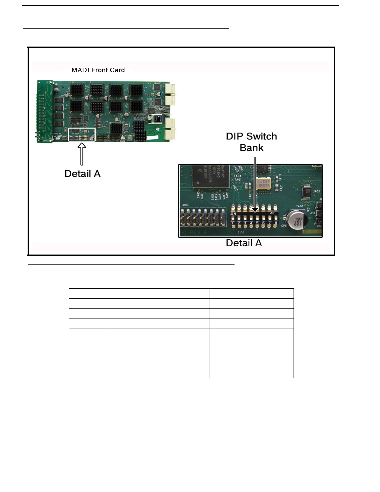
FIGURE 2. Front Card DIP Switch Location
DIP Switch Description Switch Position
8 Debug Only Mode Must be left in off position
7 Debug Only Mode Must be left in off position
6 n/a Must be left in off position
5 n/a Must be left in off position
4 n/a Must be left in off position
3 n/a Must be left in off position
2 n/a Must be left in off position
1 n/a Must be left in off position
8
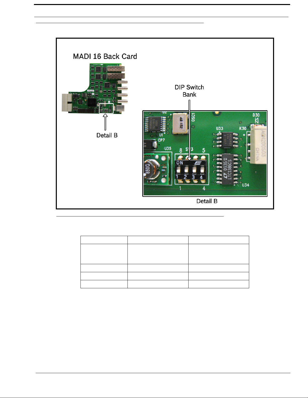
Back Card DIP Switch
Back Card DIP Switch
FIGURE 3. Back Card DIP Switch Location
DIP Switch Description Switch Position
Selects either RS-485 or
1
2n/a
3n/a
4n/a
RS-232 for the serial
pass-through port.
Off (default) - RS-485
On - RS-232
9
 Loading...