

Bosch M 60 User Manual
Modular Sensor Interface M 60
Manual
1 25/01/2019

Content
ii/104 Modular Sensor Interface M 60 Bosch Motorsport
Content
1 Preparation...................................................................................................................................................................... 5
2 Onboard Network Concept............................................................................................................................................ 6
3 Installation....................................................................................................................................................................... 7
4 Technical Data................................................................................................................................................................. 8
5 Inputs and Outputs......................................................................................................................................................... 10
5.1 Input Channels............................................................................................................................................................................................... 10
5.1.1 Analog Inputs............................................................................................................................................................................... 10
5.1.2 Digital Inputs ................................................................................................................................................................................ 10
5.2 Output Channels........................................................................................................................................................................................... 10
5.2.1 PWM Outputs .............................................................................................................................................................................. 10
5.2.2 Sensor Power Supply................................................................................................................................................................. 10
5.3 Communication Channels ......................................................................................................................................................................... 10
5.3.1 CAN Bus.......................................................................................................................................................................................... 11
5.3.2 Ethernet Channels ...................................................................................................................................................................... 11
5.3.3 RS232 Ports................................................................................................................................................................................... 11
5.3.4 Vehicle Diagnosis Connector ................................................................................................................................................. 11
5.4 Pin Layout Connectors................................................................................................................................................................................ 12
5.4.1 Pin Layout Life Connector ASDD-2-12-41PN (Red) ...................................................................................................... 12
5.4.2 Pin Layout Sensor Connector ASDD-2-12-41PA (Yellow)........................................................................................... 13
6 Mechanical Drawing ....................................................................................................................................................... 15
7 Starting up....................................................................................................................................................................... 16
7.1 Before Starting............................................................................................................................................................................................... 16
7.1.1 Setting up the Network Interface......................................................................................................................................... 16
7.1.2 Starting the M 60........................................................................................................................................................................ 17
7.1.3 About RaceCon............................................................................................................................................................................ 17
7.1.4 Connecting the M 60 to RaceCon........................................................................................................................................ 17
7.2 Assign the Mounting Location ................................................................................................................................................................ 21
7.3 Feature Activation......................................................................................................................................................................................... 24
8 Math and Condition Channels....................................................................................................................................... 26
8.1 Math Channels............................................................................................................................................................................................... 26
8.1.1 Creating a new Math Channel............................................................................................................................................... 26
8.1.2 Creating a new Conditional Function ................................................................................................................................. 27
8.2 Condition Channels...................................................................................................................................................................................... 31
8.2.1 Creating a new Condition Channel...................................................................................................................................... 31
8.2.2 Creating a new Condition Combination............................................................................................................................ 33
9 CAN Bus ........................................................................................................................................................................... 35
9.1 CAN Bus Trivia................................................................................................................................................................................................ 35
9.2 CAN Input ........................................................................................................................................................................................................ 36
9.2.1 Input Configuration ................................................................................................................................................................... 36
9.2.2 Create new CAN Channel ........................................................................................................................................................ 36
9.2.3 CAN Channel Configuration................................................................................................................................................... 37
9.2.4 Extracting Data from CAN Bus .............................................................................................................................................. 37
9.2.5 Conversion to Physical Values............................................................................................................................................... 39
9.2.6 Special Features........................................................................................................................................................................... 39
9.2.7 Online View of CAN Channels in Vehicle .......................................................................................................................... 40

Content
Bosch Motorsport Modular Sensor Interface M 60 iii/104
9.2.8 Import a CAN Database (DBC) File ...................................................................................................................................... 41
9.2.9 Export RaceCon CAN Configuration ................................................................................................................................... 42
9.2.10 Import RaceCon CAN Configuration................................................................................................................................... 42
9.3 CAN Output .................................................................................................................................................................................................... 43
9.3.1 Output Configuration ............................................................................................................................................................... 43
9.3.2 Create new CAN Output Message Channel..................................................................................................................... 43
9.3.3 Set up of Word Length, Byte Order and Quantization ................................................................................................ 45
9.3.4 Export RaceCon CAN Configuration ................................................................................................................................... 45
9.3.5 Import RaceCon CAN Configuration................................................................................................................................... 46
10 Analog and Frequency Inputs ....................................................................................................................................... 48
10.1 Features ............................................................................................................................................................................................................ 48
10.2 Measurement Channels.............................................................................................................................................................................. 48
10.3 Configuring Inputs ....................................................................................................................................................................................... 49
10.3.1 Configuring a predefined Bosch Sensor with the 'Bosch Sensor Wizard' ............................................................ 49
10.3.2 Configuring a generic linear sensor .................................................................................................................................... 51
10.3.3 Configuring a generic nonlinear sensor ............................................................................................................................ 54
10.3.4 Configuring a Multipoint Adjustment ................................................................................................................................ 57
10.3.5 Digital Filter Details.................................................................................................................................................................... 59
10.3.6 Configuring a Frequency Input ............................................................................................................................................. 60
10.4 Configuring computed Source................................................................................................................................................................ 62
10.5 Hysteresis......................................................................................................................................................................................................... 63
10.5.1 Special Functionality: Vehicle speed ................................................................................................................................... 65
10.5.2 Setting up calculated Speed................................................................................................................................................... 65
10.6 Configuring PWM Outputs ....................................................................................................................................................................... 67
11 Online Measurement ...................................................................................................................................................... 70
11.1 Achieving an online Connection............................................................................................................................................................. 70
11.1.1 Set up the PC for Access.......................................................................................................................................................... 70
11.1.2 Going online ................................................................................................................................................................................. 71
11.1.3 Configuration Download ......................................................................................................................................................... 71
11.2 Setting up an online Measurement....................................................................................................................................................... 72
11.2.1 Automatic Creation of Measurement Sheets .................................................................................................................. 76
11.2.2 Using the Measurement Sheets............................................................................................................................................ 77
11.3 Online Calibration of Measurement Channels .................................................................................................................................. 77
11.3.1 Enable online offset Calibration for Measurement Channel...................................................................................... 78
11.3.2 Performing the online offset Calibration........................................................................................................................... 78
11.4 Group Adjustment........................................................................................................................................................................................ 79
11.5 Online Calibration of Multipoint Adjustment Channels ................................................................................................................ 81
12 Error Memory .................................................................................................................................................................. 84
12.1 Error memory representation in RaceCon .......................................................................................................................................... 84
12.1.1 Accessing the memory ............................................................................................................................................................. 84
12.1.2 Clearing the error memory ..................................................................................................................................................... 85
12.2 Information on errors available from the error memory............................................................................................................... 86
12.2.1 Error Memory Properties ......................................................................................................................................................... 86
12.2.2 Error Properties ........................................................................................................................................................................... 88
12.3 Analog Input Diagnosis.............................................................................................................................................................................. 90
12.3.1 Monitoring limits / Shortcut Detection / Cable Breakage.......................................................................................... 90
12.3.2 Open Line Detection ................................................................................................................................................................. 91
13 Firmware .......................................................................................................................................................................... 92
13.1 Firmware and Configuration..................................................................................................................................................................... 92

Content
iv/104 Modular Sensor Interface M 60 Bosch Motorsport
13.2 Firmware Update........................................................................................................................................................................................... 92
14 Clone the Unit ................................................................................................................................................................. 95
15 GPS Sensor....................................................................................................................................................................... 97
15.1 GPS (Global Positioning System)............................................................................................................................................................ 97
15.2 Protocol ............................................................................................................................................................................................................ 97
15.3 Sensor Recommendation .......................................................................................................................................................................... 97
15.4 Measurement Labels ................................................................................................................................................................................... 98
15.5 GPS Troubleshooting .................................................................................................................................................................................. 99
16 Disposal............................................................................................................................................................................ 100

Preparation | 1
Bosch Motorsport Modular Sensor Interface M 60 5/104
1 Preparation
Use the M 60 only as intended in this manual. Any maintenance or repair must be performed by authorized and qualified personnel approved by Bosch Motorsport.
Operation of the M 60 is only certified with the combinations and accessories that are
specified in this manual. The use of variant combinations, accessories and other devices
outside the scope of this manual are only permitted when they have been determined to
be compliant from a performance and safety standpoint by a representative from Bosch
Motorsport. Read the manual carefully and follow the application hints step by step. Don’t
hesitate to contact us, contact data can be found on the back page of this document.
Disclaimer
Due to continuous enhancements we reserve the rights to change any illustrations, photos
and technical data within this manual.
Please retain this manual for your records.
2 | Onboard Network Concept
6/104 Modular Sensor Interface M 60 Bosch Motorsport
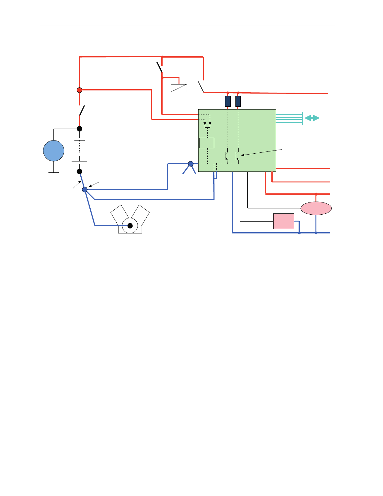
2 Onboard Network Concept
G
Engine_GND
GND_Starpoint
Chassis
KL31
LS_GND_1
LS_GND_2
Main
Switch
UBAT
Star connection
(term30)
positive terminal
Electric Loads
IGN-
Switch
KL15
SENSPWR5
SENSGND
active
Sensor
ANA_IN(xx)
NTC
Sensor
ANA_IN(xy)
switched pos. terminal
Star connection
dig. sensors
(e.g. wheelspeed)
µC
As short as
possible
SENSPWR10
UBATT_FUSE
KL30
LS_SWITCH1…4
Bosch Motorsport
diagnosis connector
PC
Device

Installation | 3
Bosch Motorsport Modular Sensor Interface M 60 7/104
3 Installation
Power Supply
Please ensure that you have a good ground installation. That means:
– A ground that has a solid, low resistance connection to the negative battery terminal.
– Connection should be free from dirt, grease, paint, anodizing etc.
– Use large diameter wire.
– More metal-to-metal contact is better!
The following notations for power signals are used:
– KL 15 is a switched battery rail controlled by the IGN-switch.
– KL 30 is an unswitched battery positive rail (same as battery positive terminal).
– KL 31 is an unswitched ground rail (same as battery negative terminal).
NOTICE
Be careful to observe current limits of wires and connector pins!

4 | Technical Data
8/104 Modular Sensor Interface M 60 Bosch Motorsport
4 Technical Data
The M 60 is a compact and light weight sensor interface unit for analog and digital
sensors. Up to eight M 60 can be used to expand the number of input channels of the
data logger C 60 as well as the display DDU 9. The M 60 are linked via high-speed Ethernet interface. This allows for synchronized acquisition of data from the different units and
the ECU.
The M 60 offers 26 analog inputs, four rotational inputs, four pwm outputs and two independent CAN buses. Each analog input channel features an analog pre-filter, 8 x oversampling and highly linear digital filtering. The cut-off frequency of the digital filter is
automatically adjusted to match the acquisition rate. The latency of the digital filters is
corrected during recording, yielding zero filter delay in the recorded data.
The evaluation of each M 60 measurement channel is individually configurable with the
PC configuration tool RaceCon.
Application
8 kHz AD converters with digital low pass filter
Configurable math channels
User configurable CAN in/out messages
Up to 1,000 Hz acquisition rate for all channels
3-port network switch
Mechanical Data
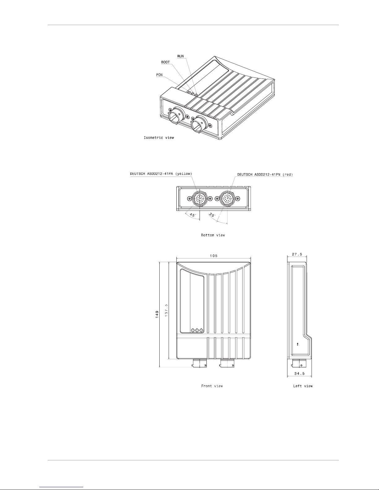
Size 105 x 34.5 x 137.5 (149) mm
Weight 495 g
Operating temperature internal -20 to 65°C
Max. vibration Vibration Profile 1 (See Appendix or
www.bosch-motorsport.com)
Electrical Data
Supply voltage 8 to 18 V
Max. power consumption (w/o loads) 10 W at 14 V

Technical Data | 4
Bosch Motorsport Modular Sensor Interface M 60 9/104
Inputs
Analog channels 26
Input range 0 to 5 V
Resolution 12 bit
Switchable pull up resistor 3 kOhm
Rotational channels (default Hall, Inductive
as option)
4
Outputs
PWM outputs (low side switch 2 A each) 4
Sensor supply 5 V (350 mA each) 4
Sensor supply 10 V (350 mA each) 1
Sensor supply 12 V (1 A, non regulated) 1
Environment
Software Upgrade 1
CCP-Master (ASAP 2 file from ECU manufacturer required)
F 02U V01 012-01
Connectors and Wires
Motorsport connectors double density 2 x 41 pins
Mating connector I
AS-DD 6-12-41SN
F 02U 002 216-01
Mating connector II
AS-DD 6-12-41SA
F 02U 004 180-01
Communication
Configuration via RaceCon over Ethernet or MSA-Box II
2 CAN interfaces
3 Ethernet 100BaseT
The required software for this device is available on our homepage www.bosch-motorsport.com

5 | Inputs and Outputs
10/104 Modular Sensor Interface M 60 Bosch Motorsport
5 Inputs and Outputs
The following chapter introduces the Input and Output Channels.
5.1 Input Channels
The M 60 provides diverse analog inputs which allows the direct connection of a multiplicity number of sensors.
5.1.1 Analog Inputs
The M 60 analog inputs accept an input signal of 0 to 5 V. A 3.01 kOhm pull-up resistor
can be activated by software.
5.1.2 Digital Inputs
The digital inputs of the M 60 accept 0 V to 5 V signals of Hall-effect sensors by default.
Connect the output of the Hall-effect sensor to the REVn_P pin and leave the REVn_M pin
open. Support of inductive speed sensors is available as a hardware option. Inductive
sensors are connected to the REVn_P and REVn_M pins.
5.2 Output Channels
This chapter describes the PMW Output and Sensor Power Supply of the M 60.
5.2.1 PWM Outputs
The M 60 has 4 low side switch outputs controlled by pulse width modulation (PWM).
Each switch is rated 1 A maximum current. Maximum PWM switch frequency is 1 kHz with
a 0 % … 100 % duty cycle. Each output is short circuit protected to GND and battery
voltage. It is mandatory to connect the LS_PWM pins to vehicle GND as indicated in the
circuit diagram when using the PWM outputs.
5.2.2 Sensor Power Supply
The M 60 has three types of sensor power supply:
– 12 V unregulated battery voltage
– 5 V regulated voltage
– 10 V regulated voltage
The 12 V unregulated output is fused and rated 1 A max. The regulated 5 V and 10 V outputs can deliver 350 mA each. They are short circuit protected to battery voltage and
GND.
5.3 Communication Channels
This chapter describes the Communication Channels of the M 60.

Inputs and Outputs | 5
Bosch Motorsport Modular Sensor Interface M 60 11/104
5.3.1 CAN Bus
The M 60 has 2 CAN buses configurable as input and output. Different baud rates are selectable. Please note that the M 60 does not contain any CAN termination resistors. Thus
the CAN termination resistors need to be integrated into the wiring loom.
5.3.2 Ethernet Channels
The M 60 has three 100 Mbit full duplex Ethernet communication ports. The ports are internally connected with an Ethernet switch. The Ethernet ports have 'cable auto crossover'
functionality.
5.3.3 RS232 Ports
The M 60 has two RS232 serial ports. The baudrate for both ports is programmable. Port 1
is reserved for online telemetry, port 2 can be used for reception of data from a serial GPS
receiver.
5.3.4 Vehicle Diagnosis Connector
The Bosch Motorsport vehicle diagnosis connector is used as a standard interface to connect the vehicle to a PC e.g. via a MSA-Box II. Loom Connector: AS0-12-35SN.
PIN Name Description Used for M 60
1 Terminal 30 Permanent positive +
2 Terminal 15 Switched positive +
3 Terminal 31 GND +
4 CAN High Diagnostic CAN bus
16 CAN Low Diagnostic CAN bus
10 K-Line ECU diagnosis
8 Ethernet RxD + Ethernet interface +
9 Ethernet RxD - Ethernet interface +
11 Ethernet TxD + Ethernet interface +
12 Ethernet TxD - Ethernet interface +
22 Screen Cable screen +

5 | Inputs and Outputs
12/104 Modular Sensor Interface M 60 Bosch Motorsport
5.4 Pin Layout Connectors
5.4.1 Pin Layout Life Connector ASDD-2-12-41PN (Red)
PIN Name Description Direction Remark
1 UBATT (Kl. 30) power supply Ubat input
2 switched posit-
ive Kl.15
switched power supply Ubat input
3 switched posit-
ive Kl.15
switched power supply Ubat input
4 unit ground (Kl.
31)
ground power supply input
5 unit ground ground power supply input
6 ETH1_TX+ Ethernet interface 1
(10/100BaseT)
bidirectional
dataline
7 ETH1_TX- Ethernet interface 1
(10/100BaseT)
bidirectional
dataline
8 ETH1_RX+ Ethernet interface 1
(10/100BaseT)
bidirectional
dataline
9 ETH1_RX- Ethernet interface 1
(10/100BaseT)
bidirectional
dataline
10 ETH_SCR screen for Ethernet screen
11 ETH2_TX+ Ethernet interface 2
(10/100BaseT)
bidirectional
dataline
12 ETH2_TX- Ethernet interface 2
(10/100BaseT)
bidirectional
dataline
13 ETH2_RX+ Ethernet interface 2
(10/100BaseT)
bidirectional
dataline
14 ETH2_RX- Ethernet interface 2
(10/100BaseT)
bidirectional
dataline
15 ETH3_TX+ Ethernet interface 3
(10/100BaseT)
bidirectional
dataline
16 ETH3_TX- Ethernet interface 3
(10/100BaseT)
bidirectional
dataline
17 ETH3_RX+ Ethernet interface 3
(10/100BaseT)
bidirectional
dataline
18 ETH3_RX- Ethernet interface 3
(10/100BaseT)
bidirectional
dataline
19 CAN1_H CAN interface 1 (up to 1
Mbit/s)
bidirectional
dataline
MS 3/MS 4 CardMemory
20 CAN1_L CAN interface 1 (up to 1
Mbit/s)
bidirectional
dataline
MS 3/MS 4 CardMemory
21 CAN2_H CAN interface 2 (up to 1
Mbit/s)
bidirectional
dataline
22 CAN2_L CAN interface 2 (up to 1
Mbit/s)
bidirectional
dataline

Inputs and Outputs | 5
Bosch Motorsport Modular Sensor Interface M 60 13/104
PIN Name Description Direction Remark
23 Not connected Unused Spare
24 Not connected Unused Spare
25 Not connected Unused Spare
26 Not connected Unused Spare
27 SENSPWR5_1 5 V power supply for analog
sensors
output
28 SENSGND_1 sensor ground 1 output
29 TimeSync signal of synchronisation input used for timing of
system components
30 LS_GND_1 PWM ground output
31 LS_SWITCH_1 PWM lowside switch 1 input
32 LS_SWITCH_2 PWM lowside switch 2 input
33 LS_SWITCH_3 PWM lowside switch 3 input
34 LS_SWITCH_4 PWM lowside switch 4 input
35 LS_GND_2 PWM ground output
36 ANA01 analog signal 1 input
37 ANA02 analog signal 2 input
38 ANA03 analog signal 3 input
39 ANA04 analog signal 4 input
40 ANA05 analog signal 5 input
41 ANA06 analog signal 6 input
5.4.2 Pin Layout Sensor Connector ASDD-2-12-41PA
(Yellow)
PIN Name Description Direction Remark
1 UBATT_FUSE1 battery voltage supply output
2 SENSPWR10_1 10 V power supply for ana-
log sensors
output
3 SENSPWR5_2 5 V power supply for analog
sensors
output
4 SENSPWR5_3 5 V power supply for analog
sensors
output
5 SENSPWR5_4 5 V power supply for analog
sensors
output
6 SENSGND_2 sensor ground 2 output
7 SENSGND_3 sensor ground 3 output
8 Not connected Unused Spare Do not connect
9 Not connected Unused Spare Do not connect
10 RS232_2_TX RS232_2 transmit data bidirectional
dataline
used for GPSsensor

5 | Inputs and Outputs
14/104 Modular Sensor Interface M 60 Bosch Motorsport
PIN Name Description Direction Remark
11 RS232_2_RX RS232_2 receive data bidirectional
dataline
used for GPSsensor
12 RS232_GND RS232 ground
13 REV1_P speed signal 1 positive (ind.
and hall)
input
14 REV1_M speed signal 1 negative
(ind.)
input
15 REV2_P speed signal 2 positive (ind.
and hall)
input
16 REV2_M speed signal 2 negative
(ind.)
input
17 REV3_P speed signal 3 positive (ind.
and hall)
input
18 REV3_M speed signal 3 negative
(ind.)
input
19 REV4_P speed signal 4 positive (ind.
and hall)
input
20 REV4_M speed signal 4 negative
(ind.)
input
21 ANA07 analog signal 7 input
22 ANA08 analog signal 8 input
23 ANA09 analog signal 9 input
24 ANA10 analog signal 10 input
25 ANA11 analog signal 11 input
26 ANA12 analog signal 12 input
27 ANA13 analog signal 13 input
28 ANA14 analog signal 14 input
29 ANA15 analog signal 15 input
30 ANA16 analog signal 16 input
31 ANA17 analog signal 17 input
32 ANA18 analog signal 18 input
33 ANA19 analog signal 19 input
34 ANA20 analog signal 20 input
35 ANA21 analog signal 21 input
36 ANA22 analog signal 22 input
37 ANA23 analog signal 23 input
38 ANA24 analog signal 24 input
39 ANA25 analog signal 25 input
40 ANA26 analog signal 26 input
41 Not connected Unused spare
Mechanical Drawing | 6
Bosch Motorsport Modular Sensor Interface M 60 15/104
6 Mechanical Drawing

7 | Starting up
16/104 Modular Sensor Interface M 60 Bosch Motorsport
7 Starting up
The following chapter explains what you have to do before starting the M 60 and how to
connect it to RaceCon.
7.1 Before Starting
Install the software required for M 60 operation. It is developed for Windows 2000/XP/
Vista/7. Following software versions are used in this manual:
– M 60 setup, configuration and calibration: RaceCon 2.1.0
– Measurement data analysis: WinDarab V7
Set up the 100 Mbit Ethernet connection to the M 60.
– All three Ethernet ports of M 60 are internally connected by a network switch.
– All Ethernet ports have ‘cable auto crossover’ functionality.
Minimum wiring loom of the Life connector (red):
PIN Description
1+2+3 12 V Supply Voltage
4+5 GND Supply Voltage
6 Ethernet Tx+
7 Ethernet Tx-
8 Ethernet Rx+
9 Ethernet Rx-
10 Ethernet Screen
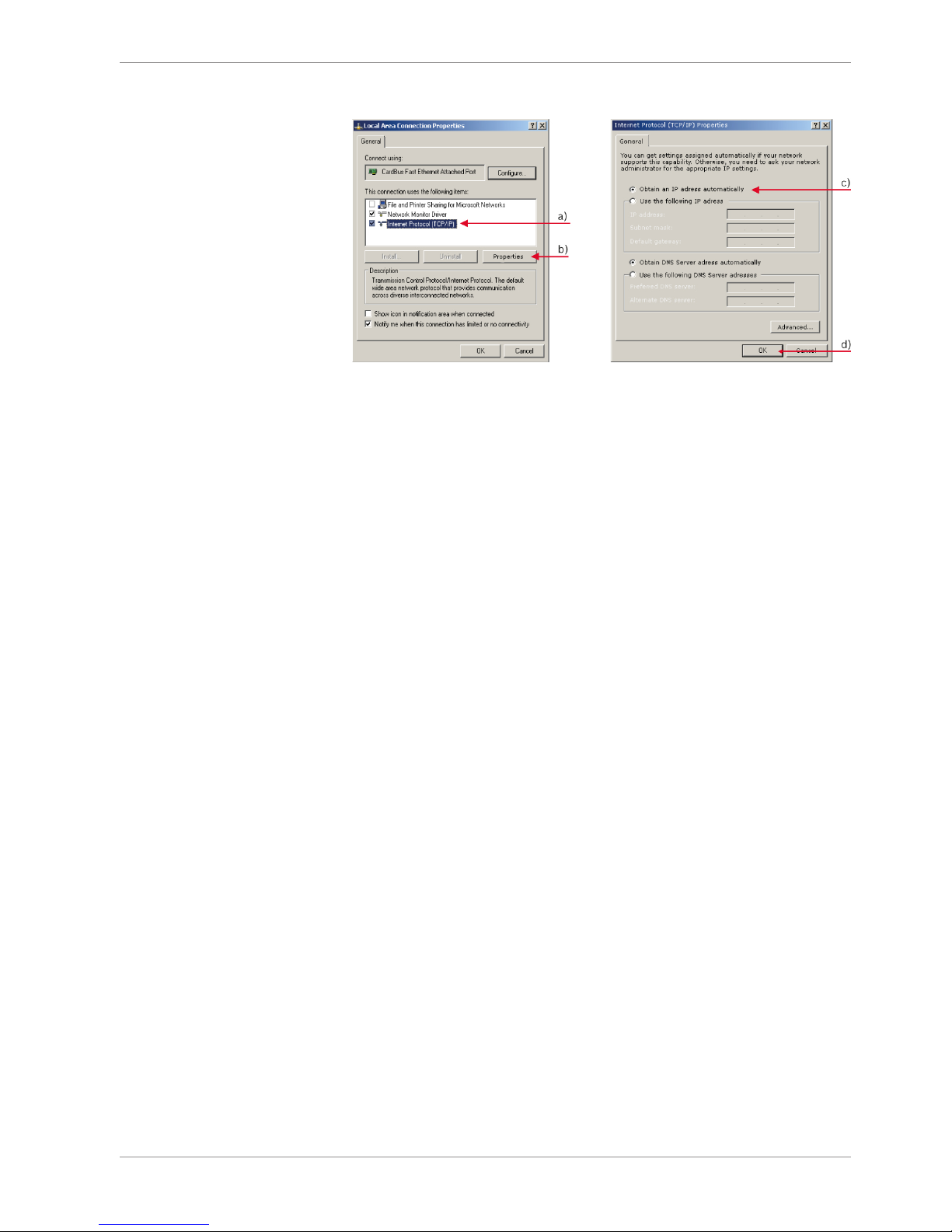
7.1.1 Setting up the Network Interface
The M 60 contains a DHCP server, network addresses can be assigned automatically to the
configuration PC.
1. Switch off the PC’s firewall.
Starting up | 7
Bosch Motorsport Modular Sensor Interface M 60 17/104
2. Set up the PC’s network interface as shown in the screenshots.
a) Select ‘Internet Protocol (TCP/IP)’.
b) Click ‘Properties’.
c) Select ‘Obtain an IP address automatically’.
d) Click ‘OK’ when done.
7.1.2 Starting the M 60
The M 60 powers up by turning on the ignition of the car.
The ‘Link LED’ at the PC’s network adapter will illuminate. If the LED is off, check the wiring
harness.
7.1.3 About RaceCon
RaceCon is an all integrated software tool for configuration and calibration of Bosch Motorsport hardware products. It is used to set up, configure and calibrate the M 60.
For better understanding, Bosch Motorsport offers a video tutorial that explains many
functions of RaceCon.
The video tutorial is available in the ‘Software Download’ section of www.bosch-motorsport.com.
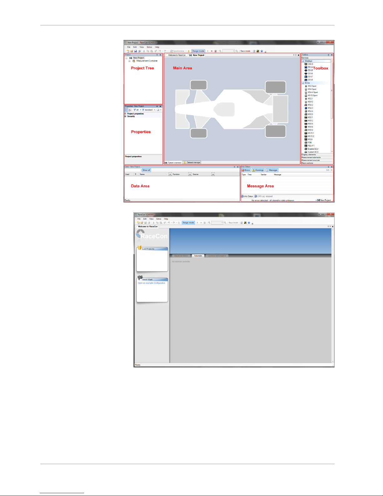
7.1.4 Connecting the M 60 to RaceCon
The following screenshot shows an overview of the RaceCon main screen with its areas. All
(sub-)windows are resizable and dockable.
7 | Starting up
18/104 Modular Sensor Interface M 60 Bosch Motorsport
1. Start the RaceCon software.
Starting up | 7
Bosch Motorsport Modular Sensor Interface M 60 19/104
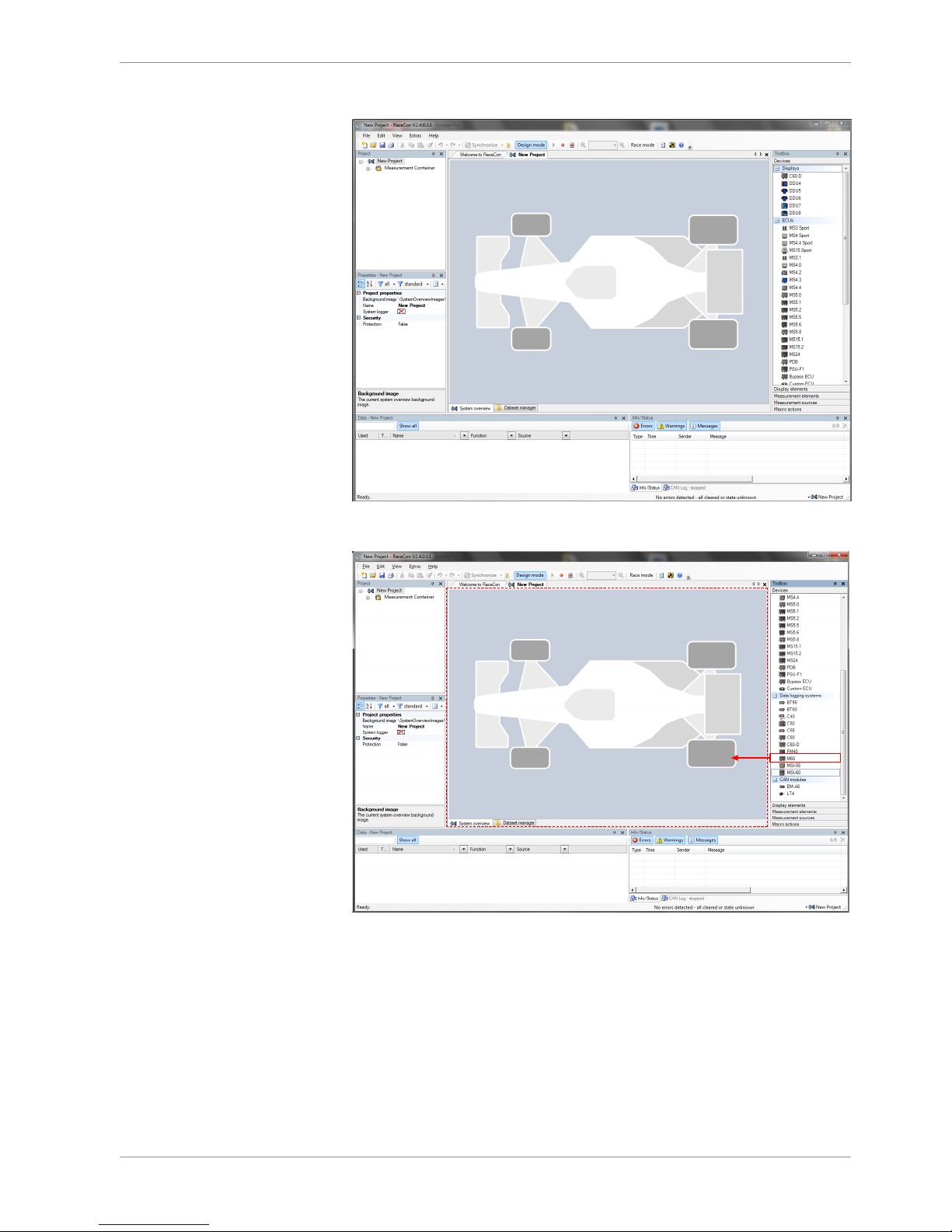
2. In the ‘File’ menu select ‘New’ to create a new project.
3. In the Toolbox select the M 60 and drag it into the Main Area. A pop-up window to
specify the M 60 program archive appears.
7 | Starting up
20/104 Modular Sensor Interface M 60 Bosch Motorsport
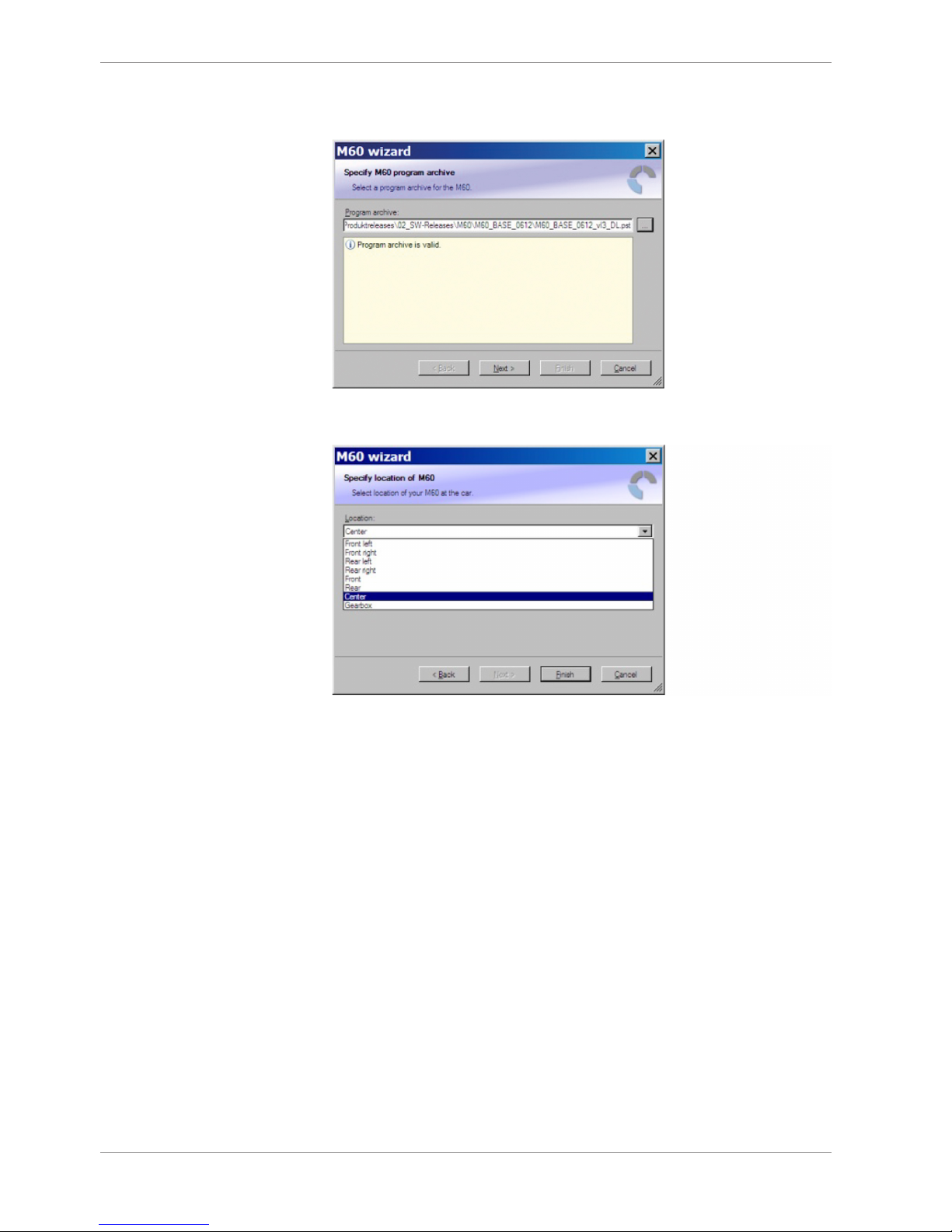
4. Select the program archive delivered with the M 60 (.PST file). An information shows if
the archive is valid or not.
5. Click ‘Next’.
6. Select location of M 60.
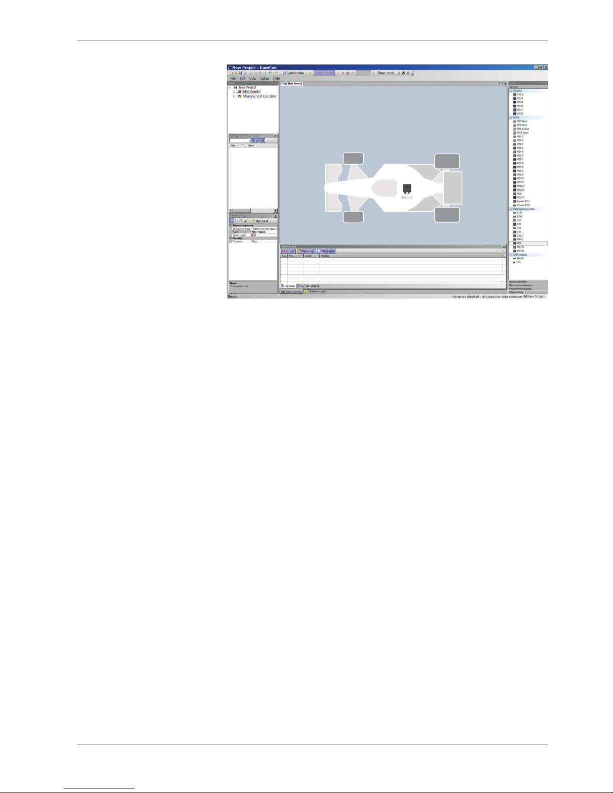
7. Click ‘Finish’. The M 60 is inserted into the project and RaceCon tries to connect to the
device. Repeat the bespoken procedure for every additional M 60. If you are starting
with a new delivered M 60 you once-only need to assign the mountain location(s).
Please refer to Assign the Mounting Location.
Starting up | 7
Bosch Motorsport Modular Sensor Interface M 60 21/104
RaceCon detects configuration differences between the M 60and the RaceCon project
and asks for permission for data download.
8. Click ‘OK’ to proceed.
The download starts and the M 60 carries out a reset. After the reset RaceCon reconnects
to the M 60. Local configuration on both the PC and M 60 match (indicated by green
background and dot). The M 60 is now connected to RaceCon.
7.2 Assign the Mounting Location
Because up to eight M 60 can be used in one network for I/O expansion, the mounting
location is used for determination between the different M 60.
At delivery no mounting location is set. This is signaled by an orange ‘RUN’ LED on the
device. Therefore one must first assign a mounting location to the M 60 before it can be
used in the project. The mounting location is permanently saved in the M 60. If necessary
you can at any time reassign a different mounting location following the same procedure.
A mounting location must not be used several times in one network, this would disturb
the functionality of the respective M 60.
7 | Starting up
22/104 Modular Sensor Interface M 60 Bosch Motorsport
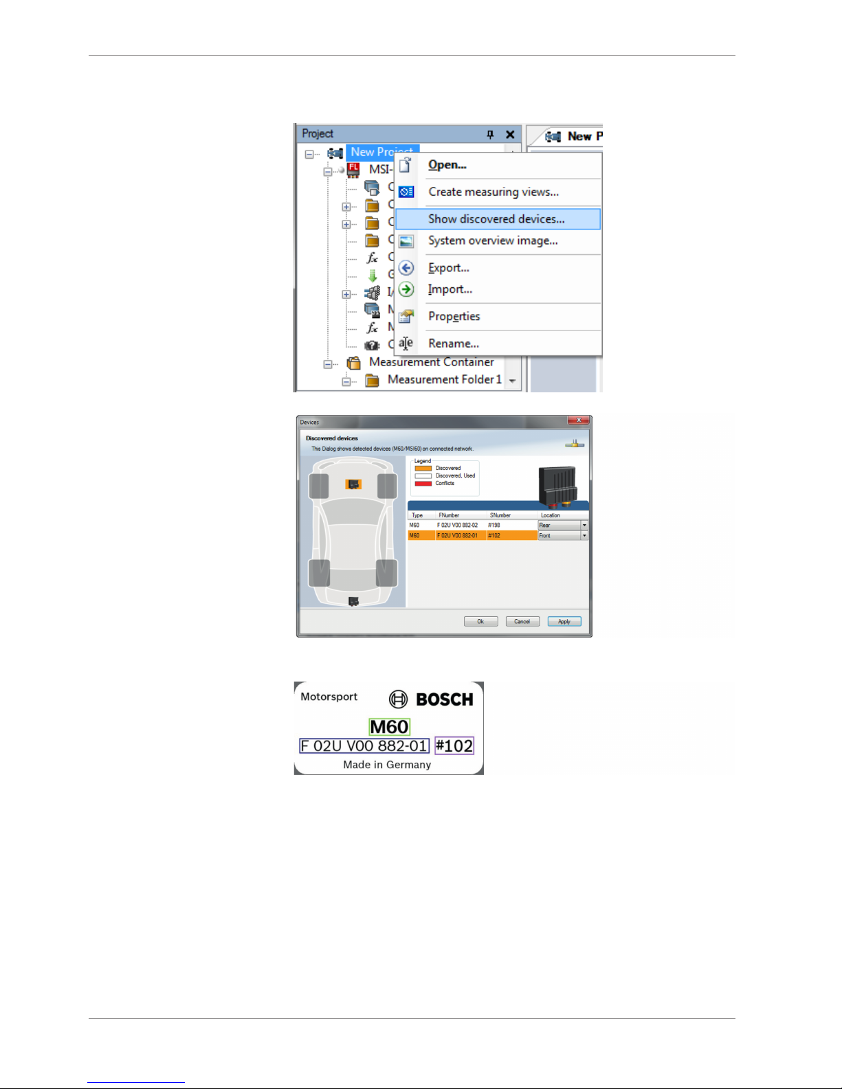
1. In the Project Tree right click on the project name e.g. ‘New Project’ and then select
‘Show discovered devices…’.
All connected M 60 are listed.
2. Compare the listed device Type, FNumber and SNumber to the identification plate to
identify the device you want to make changes to:

Starting up | 7
Bosch Motorsport Modular Sensor Interface M 60 23/104
3. Assign the desired mounting location (e.g. ‘Front’) and confirm by clicking ‘Apply’.
The mounting location is now stored in the device. The device will do a reset and the
‘RUN’ LED on the device will change to green. The list will show the new mounting
location assignment.
It is good practice to physically label the M 60 with its mounting location.
Now the device is ready to be used.
A different coloring of the M 60 is used to indicate that the device is already configured in the currently loaded RaceCon project or not (white/orange).
A conflict of several connected M 60 using the same location is indicated by red coloring the involved devices:
7 | Starting up
24/104 Modular Sensor Interface M 60 Bosch Motorsport
7.3 Feature Activation
– If you have purchased an optional software feature package, it must be activated be-
fore it becomes operational.
– The feature activation status is stored permanently in the device and requires activat-
ing once only.
– As the activation key is device specific, a key delivered with one M 60 does not work
on any other M 60.
– If you have not purchased an option package, the next steps can be skipped.
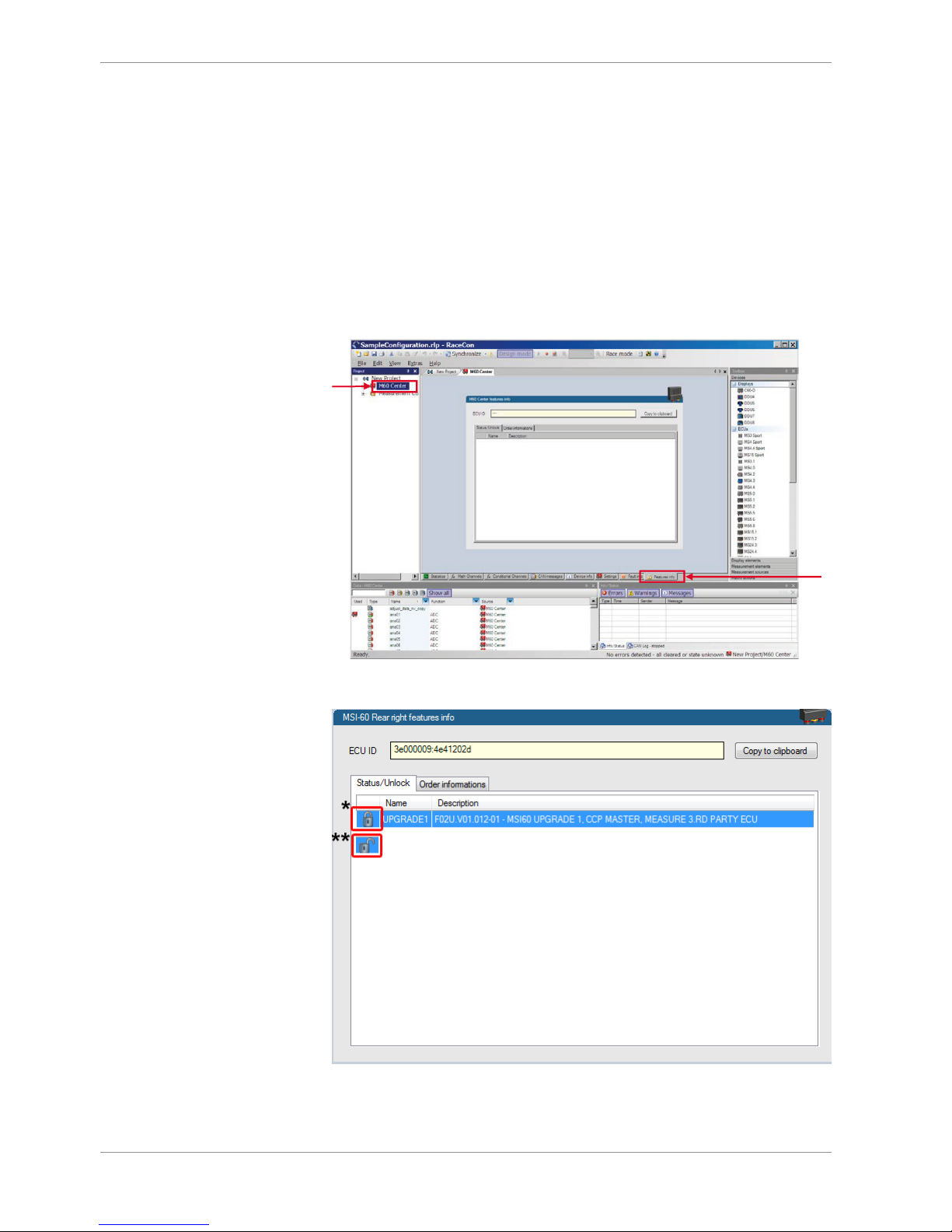
1. To activate a feature, double-click on ‘M 60’ in the Project Tree and click on the ‘Features info’ tab in the Main Area.
a) Double-click on 'M 60'.
b) Click on 'Features Info'.
a)
b)
2. Double-click on the feature you want to activate.
Starting up | 7
Bosch Motorsport Modular Sensor Interface M 60 25/104
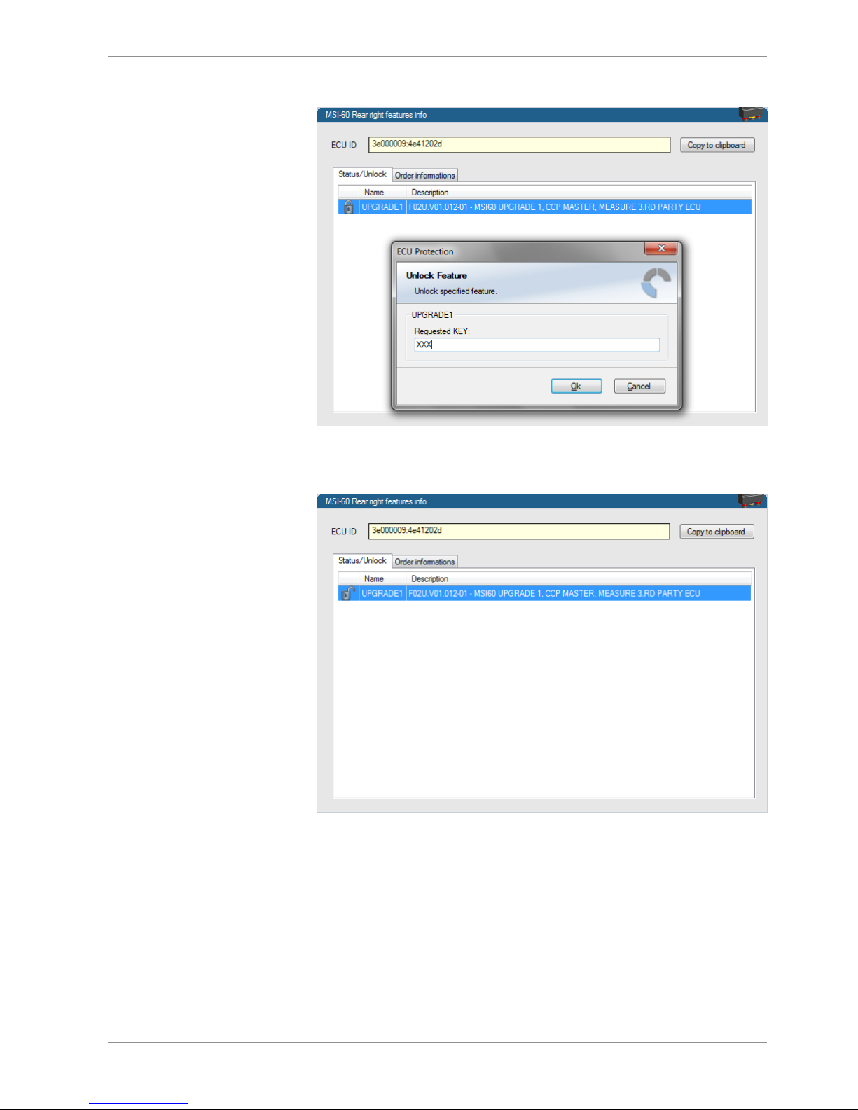
A feature unlock window appears.
3. Enter the activation key you received for this feature on this device and click ‘OK’
when done.
The feature’s status changes to ‘unlocked’.
4. Perform these steps to activate other features you purchased. Switch the car’s ignition
off and on again to cycle the power of the M 60.
8 | Math and Condition Channels
26/104 Modular Sensor Interface M 60 Bosch Motorsport
8 Math and Condition Channels
This chapter describes how to create a Math or Condition Channel.
8.1 Math Channels
Math channel
– Arithmetic and logical operations on up to 4 measurement channel(s)
– Numerical result
– Result can be used as input source for various display elements (numeric elements,
alarms, Bargraphs) and further calculations in the whole RaceCon project
Conditional function
– Arithmetic and logical operations on one or more measurement channel(s)
– If-Else structure with reset
– Numerical result
– Result can be used as input source for various display elements (numeric elements,
alarms, Bargraphs) and further calculations in the whole RaceCon project
All math channels can be used globally in the whole M 60 project.
8.1.1 Creating a new Math Channel
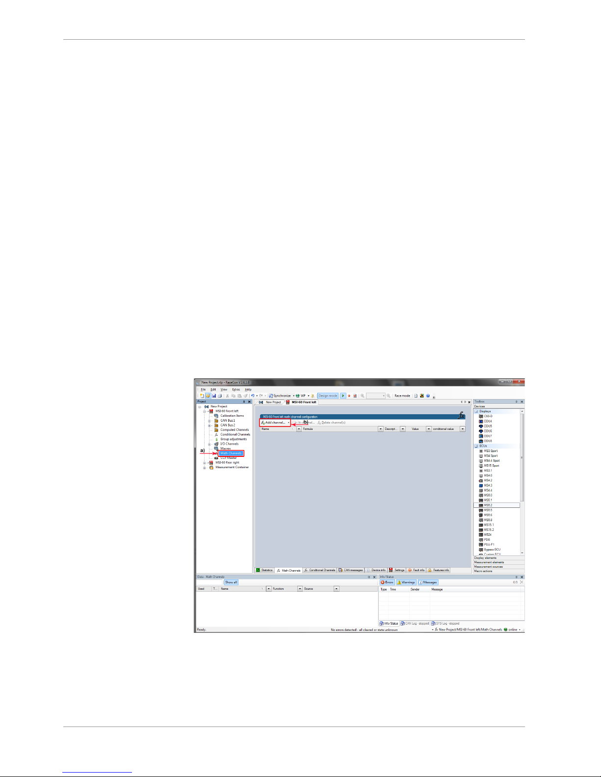
Follow the steps shown in the screenshots.
a) Double-click on ‘Math Channels’ in Project Tree.
b) Click on ‘Add channel’.
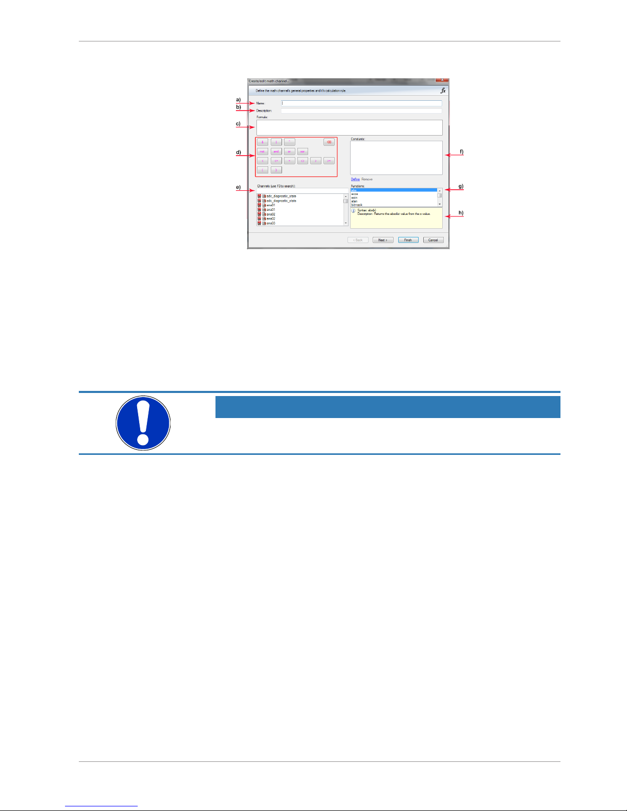
The ‘create/edit math channel’ window appears.
Math and Condition Channels | 8
Bosch Motorsport Modular Sensor Interface M 60 27/104
1. Define the math channel using the following configuration possibilities:
a) Enter the name of the math channel.
b) Enter a description of the math channel.
c) Enter the formula.
d) Select the logical operator.
e) Choose a measurement channel.
f) Define a value that can be used as a constant in the formula.
g) Choose a function.
h) Describes the function selected above.
NOTICE
To select an input channel from a specific device, put the device
name enclosed by ´#´ in front of it, e.g. #M 60 Left#time_sec
2. Click ‘Finish’ when done.
The math channel is displayed in the M 60 math channel window.
8.1.2 Creating a new Conditional Function
Follow the steps shown in the screenshots.
8 | Math and Condition Channels
28/104 Modular Sensor Interface M 60 Bosch Motorsport
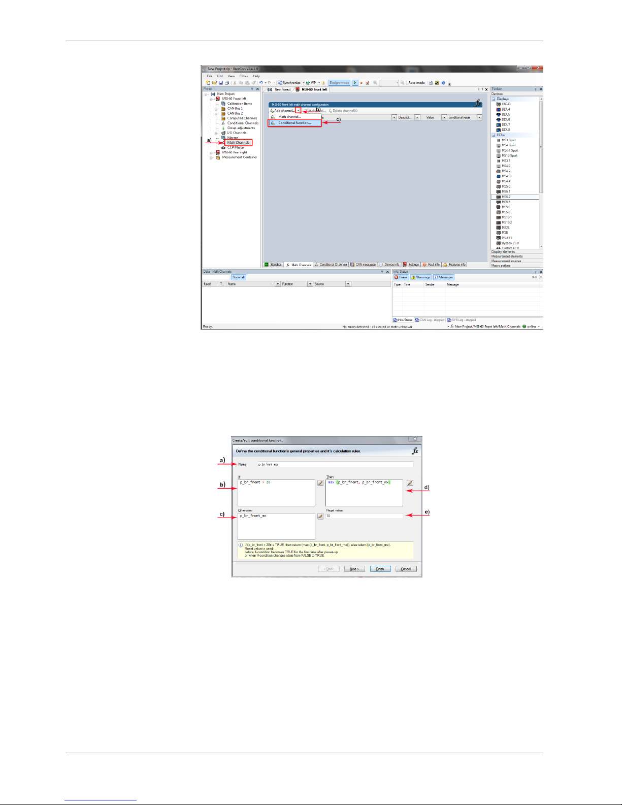
a) Double-click on ‘Math Channels’ in Project Tree.
b) Click on the dropdown arrow beside ‘Add channel’.
c) Choose ‘Conditional Function’.
The ‘create/edit conditional function’ window appears.
1. Define the conditional function using the following configuration possibilities in the
picture above.
a) Enter the name of the conditional function.
b) Enter the If-condition. Click on the pencil symbol to open an editor to enter
expressions.
c) Enter the Then-condition. Click on the pencil symbol to open an editor to
enter expressions.
d) Enter the Otherwise-condition. Click on the pencil symbol to open an editor
to enter expressions.
e) Enter the reset value (must be a number).
2. Click ‘Finish’ when done.
The conditional function is displayed in the M 60 math channel window.
Math and Condition Channels | 8
Bosch Motorsport Modular Sensor Interface M 60 29/104
NOTICE
To select an input channel from a specific device put the device
name enclosed by ´#´ in front of it. E.g. #M 60 Front Left#time_sec
The conditional function works in the following way:
The program always calculates the condition entered in the IF window and checks if the
condition is TRUE or FALSE.
If the condition entered in the IF window is TRUE, the program calculates the condition
entered in the THEN window. The returned value is the content of the new variable
(entered in ‘Name’).
If the condition entered in the IF window is FALSE, the program calculates the condition
entered in the OTHERWISE window. The returned value is the content of the new variable
(entered in ‘Name’).
The reset value is always set for the new variable (entered in ‘Name’):
– before If-condition becomes TRUE for the first time after power-up.
– when If-condition changes state from FALSE to TRUE.
An example of a condition to set up the maximum front brake pressure is given on the
next page.
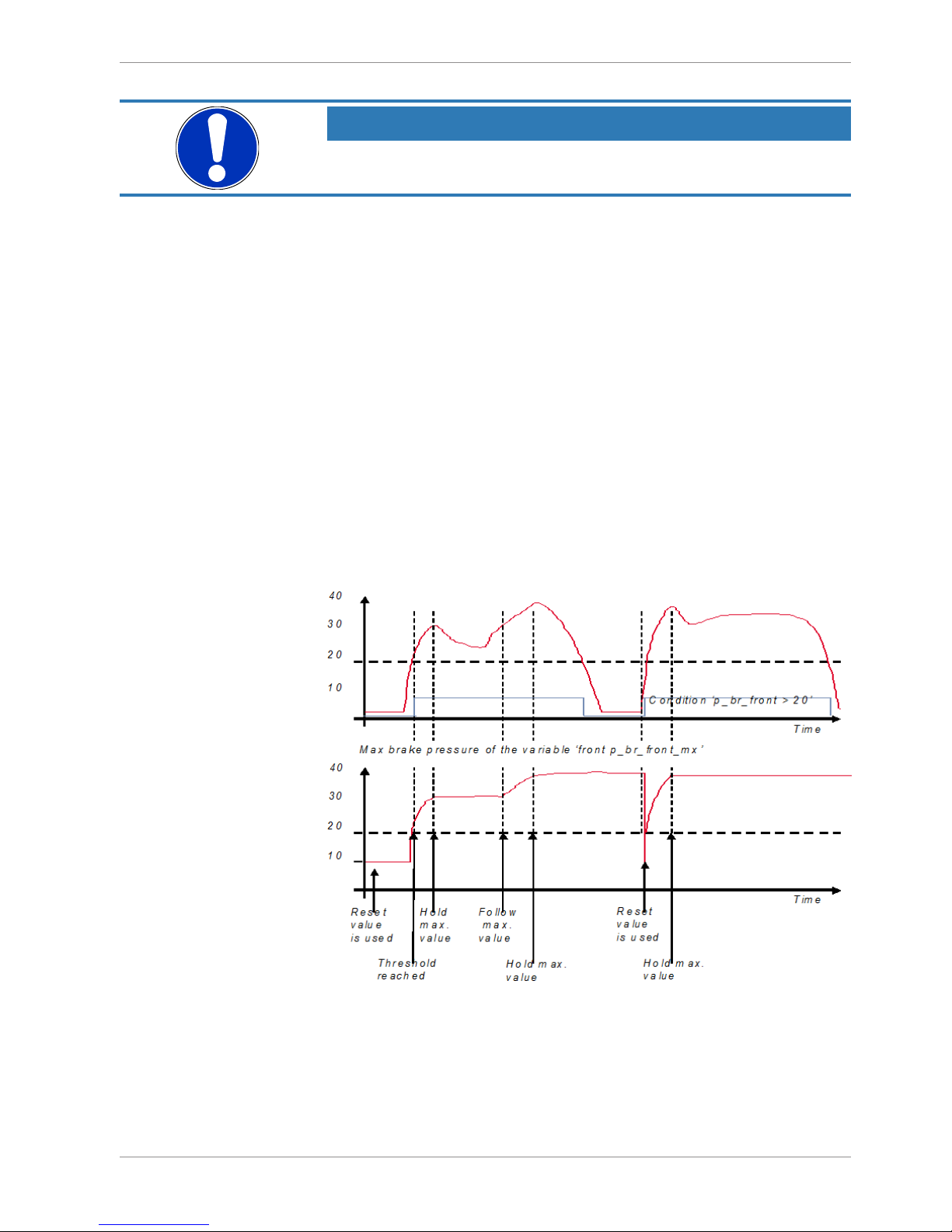
Example: Setting up a condition for maximum front brake pressure.
“Brake pressure front ‘p_br_front’”
– At power-up, the reset value (10) is used for ‘p_br_front_mx’.
– ‘p_br_front’ rises to 30. As ‘p_br_front’ is > 20 (condition is TRUE), the condition ‘max
(p_br_front, p_br_front_mx)’ in the THEN window is triggered. The condition sets the
bigger value as new value for ‘p_br_front_mx’. As ‘p_br_front’ (30) is bigger than
‘p_br_front_mx’ (10), the new value for ‘p_br_front_mx’ is set to 30.

8 | Math and Condition Channels
30/104 Modular Sensor Interface M 60 Bosch Motorsport
– Although ‘p_br_front’ falls to 25, the value of ‘p_br_front_mx’ stays 30. This is caused
by the THEN-condition, because p_br_front_mx’ (30) is still bigger than
p_br_front’ (25).
– As ‘p_br_front’ rises to 40. As ‘p_br_front’ (40) is bigger than ‘p_br_front_mx’ (30), the
new value for ‘p_br_front_mx’ is set to 40.
– As ‘p_br_front’ falls below 20, the IF-condition turns to FALSE. Now the OTHERWISE-
condition is triggered. Because the condition ‘p_br_front_mx’ sets the value of
‘p_br_front_mx’ and the value that is already set to 40 before, nothing changes.
– When ‘p_br_front’ rises to 40, the If-condition changes to TRUE again and triggers the
THEN-condition. Now the reset value (10) is used for ‘p_br_front_mx’ in the THENcondition.
– Because 40 is bigger than 10 the new value of ‘p_br_front_mx’ is 40.
 Loading...