

Page 1
LTC9412/00
Security Systems
Installation Manual
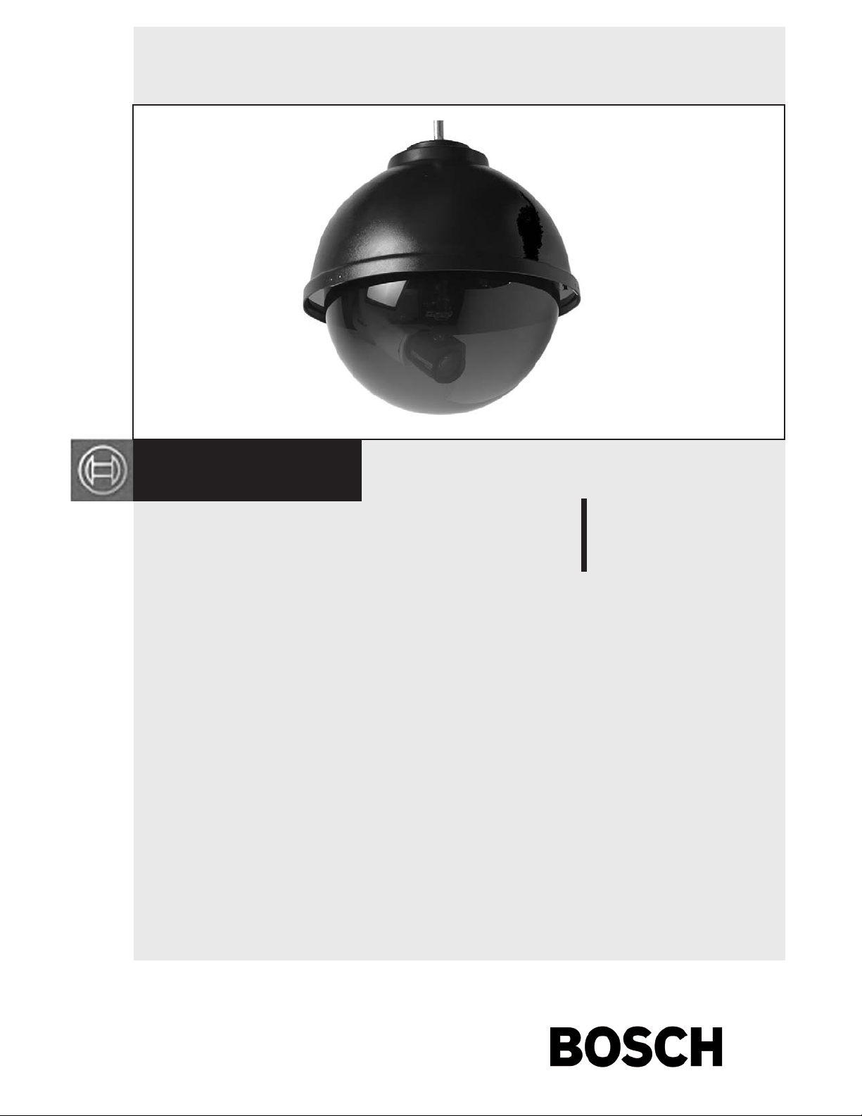
Indoor Pendant Mount Dome
EN
Page 2
LTC9412/00 Instruction Manual Introduction
Table of Contents
1 DESCRIPTION
2 UNPACKING
3 SERVICE
4 INSTALLATION
5 EXPLODED VIEW
EN
2
2
2
2
2
3
1 DESCRIPTION
The LTC9412/00 is a 12” pendant mount ceiling dome for
indoor applications. The housing top is black ABS plastic
2 UNPACKING
Unpack carefully. This is a mechanical equipment and should
be handled carefully.
Check for the following items:
• Model No. of unit
If an item appears to have been damaged in shipment, replace
it properly in its carton and notify the shipper. If any items are
missing, notify your Bosch CSS Sales Rep re sen ta tive or Customer Service.
The shipping carton is the safest container in which the unit
may be transported. Save it for possible future use.
3 SERVICE
If the unit ever needs repair service, the customer should
contact the nearest Bosch Security Systems Service Center for
authorization to return and shipping instructions.
4 INSTALLATION
This installation should be made by qualifi ed service personnel and
conform to the National Electrical Code and applicable local codes.
Please read these instructions carefully before
proceeding, and heed all cautions.
!
4.1. Remove contents from the box and check to be sure all pieces are
included.
4.2. Select the desired location for the installation. It must be a secure
mounting structure, and the completed installation must be able to
support 3 times its weight.
4.3. Determine the desired height for the unit. Measure from the
ceiling to the top of the housing (the housing is approximately 18”
tall). Add 8” for the interior of the LTC9412. Obtain 1/2” electri cal conduit and hardware to mount to the ceiling. Cut the conduit
to the measured length. Mount the conduit to the ceiling.
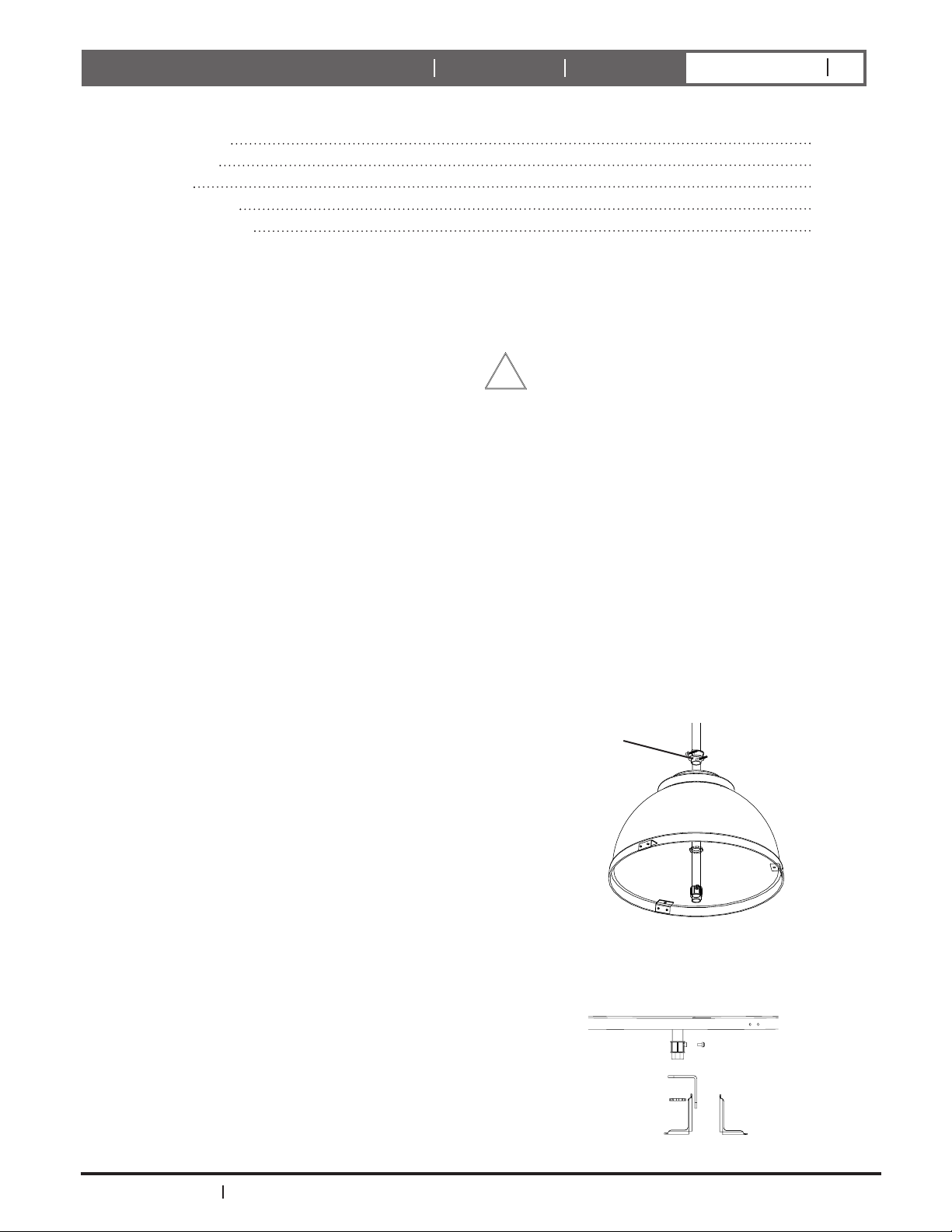
4.4. Slide the Clamp Connector and housing up the conduit so that
the end of the conduit is approximately level with the bottom of
the housing. Tighten the 2 Phillips head screws (Figure 1).
Clamp connector
with 2 Phillips head
screws
Service Centers
U.S.A.: Phone: 800-366-2283 or 408-956-3895
fax: 800-366-1329 or 408-956-3896
e-mail: NationalServiceCenter@ca.slr.com
Canada: 514-738-2434
Europe, Middle East & Asia Pacifi c Regions:
32-1-440-0711
For additional information, see www.boschsecuritysystems.com
Bosch Security Systems
14 November 2003
Figure 1 Slide housing and connector onto conduit
4.5. Completely seat the EMT con nec tor to the end of the con duit and
tighten the set screw (Figure 2).
Figure 2 Place the EMT connector on the conduit
Page 3

LTC9412/00 Instruction Manual Installation
EN
3
4.6. Remove the set screw and drill an approximately 7/32" hole
at the point where the set screw dimples the conduit. Remove
the burrs and replace the set screw.
4.7. Attach the longer arm of the camera bracket to the end of
EMT connector using the clamp nut. Tighten (Figure 3).
Figure 3 Attach bracket arm to EMT connector
4.8. Attach the other bracket arm using a carriage bolt, 5/16”
washer, lockwasher, and hex nut. The camera mounting side
may be facing either in or out (Figure 4).
5 EXPLODED VIEW
A
B
C
D
E
F
Figure 4 Attach other bracket arm
4.9. Connect the camera to the camera bracket and adjust to desired
viewing position. Tighten all connections. Complete wiring of
the camera.
4.10. Place the liner inside the dome. Hold the dome and liner up to
the housing and align the 3 Hartwell Fasteners in the dome to
the match ing holes on the housing. Ensure that the cutout in
the liner is aligned with the camera. Once it’s correctly
positioned attach the dome to the housing by pressing the
Hartwell Fasteners into the fl ange of the dome (Figure 5).
Hartwell Fasteners
Figure 5 Attach the dome to the housing
G
Description Part number Qty.
A Clamp connector 70-WPCR02 1
B 12" ABS housing (black) 21-TOP123 1
C EMT connector 70-WPCR01 1
D Camera bracket 30-VL1361 1
E 12" dome liner 20-LNOP123 1
F Hartwell fastener 95-FSPLO1(2) 3
G 12" OP clear dome RCOP123 1
A
B
C
D
E
F
G
H
I
Description Qty.
A VL1361 bracket 1
B 1/4-20 hex nut 1
C 1/4" split lockwasher 1
D 1/4" fl at washer 1
E FM2 bracket 1
F 5/16" washer 1
G 1/4-20 x 3/4" carriage bolt 1
H 1/4-20 x 1/2" hex bolt 1
Bosch Security Systems
14 November 2003
Page 4

Bosch Security Systems, Inc.
850 Greenfield Road
Lancaster, PA 17601 EE.UU.
Te l: 800-326-3270
Fax: 1-717-735-6560
www.boschsecuritysystems.com
Robert Bosch GmbH
Geschäftsbereich
Postfach 10 60 50
70049 Stuttgart
Te lefax (0711) 811-1234
Bosch Security Systems B.V.
P.O. Box 80002
5600 JB Eindhoven
The Netherlands
Te le +31 40 27 80000
© 2003 Bosch Security Systems GmbH
14 November 2003
Data subject to change without notice.3935 890 15611
 Loading...