

Page 1
Instruction Manual
EN Alarm Interface Units
Instructions d’installation
FR Alarm Interface Units
Installationsanleitungen
DE Alarm Interface Units
Instrucciones de instalación
ES Alarm Interface Units
Installatie-instructies
NL Alarm Interface Units
Istruzioni per l’installazione
IT Alarm Interface Units
LTC 8540/00 Series
Page 2

LTC 8540/00 Series | Instruction Manual | Contents
EN
|
2
Bosch Security Systems | December 13, 2007
EN Installation Instructions . . . . . . . . . . . . . . . . . . . . . . . . . . . . . . . . . . . . . . . . . . . . . . . . . . . . . . . . . . . . .2
FR Manuel d’utilisation . . . . . . . . . . . . . . . . . . . . . . . . . . . . . . . . . . . . . . . . . . . . . . . . . . . . . . . . . . . . . . .12
DE Installationshinweise . . . . . . . . . . . . . . . . . . . . . . . . . . . . . . . . . . . . . . . . . . . . . . . . . . . . . . . . . . . . . . .22
ES Instrucciones para la instalación . . . . . . . . . . . . . . . . . . . . . . . . . . . . . . . . . . . . . . . . . . . . . . . . . . . . . .30
NL Bedieningsvoorschrift . . . . . . . . . . . . . . . . . . . . . . . . . . . . . . . . . . . . . . . . . . . . . . . . . . . . . . . . . . . . . .38
IT Istruzioni per l’installazione . . . . . . . . . . . . . . . . . . . . . . . . . . . . . . . . . . . . . . . . . . . . . . . . . . . . . . . . .46
Page 3

EN|3
Bosch Security Systems | December 13, 2007
LTC 8540/00 Series | Instruction Manual | Important Safegaurds
Important Safeguards
1. Read, Follow, and Retain Instructions - All safety
and operating instructions should be read and
followed before operating the unit. Retain instructions
for future reference.
2. Heed Warnings - Adhere to all warnings on the unit
and in the operating instructions.
3. Attachments - Attachments not recommended by
the product manufacturer should not be used, as they
may cause hazards.
4. Installation Cautions - Do not place this unit on an
unstable stand, tripod, bracket, or mount. The unit
may fall, causing serious injury to a person and
serious damage to the unit. Use only manufacturerrecommended accessories, or those sold with the
product. Mount the unit per the manufacturer's
instructions. Appliance and cart combination should
be moved with care. Quick stops, excessive force, or
uneven surfaces may cause the appliance and cart
combination to overturn.
5. Cleaning - Unplug the unit from the outlet before
cleaning. Follow any instructions provided with the
unit. Generally, using a damp cloth for cleaning is
sufficient. Do not use liquid cleaners or aerosol
cleaners.
6. Servicing - Do not attempt to service this unit
yourself. Opening or removing covers may expose
you to dangerous voltage or other hazards. Refer all
servicing to qualified service personnel.
7. Damage Requiring Service - Unplug the unit from
the main AC power source and refer servicing to
qualified service personnel under the following
conditions:
• When the power supply cord or plug is damaged.
• If liquid has been spilled or an object has fallen
into the unit.
• If the unit has been exposed to water and/or
inclement weather (rain, snow, etc.).
• If the unit does not operate normally, when
following the operating instructions. Adjust only
those controls specified in the operating
instructions. Improper adjustment of other controls
may result in damage, and require extensive work
by a qualified technician to restore the unit to
normal operation.
• If the unit has been dropped or the cabinet
damaged.
• If the unit exhibits a distinct change in
performance, this indicates that service is needed.
8. Replacement Parts - When replacement parts are
required, the service technician should use
replacement parts specified by the manufacturer or
that have the same characteristics as the original part.
Unauthorized substitutions may result in fire,
electrical shock or other hazards.
9. Safety Check - Upon completion of servicing or
repairs to the unit, ask the service technician to
perform safety checks to ensure proper operating
condition.
10. Power Sources - Operate the unit only from the type
of power source indicated on the label. If unsure of
the type of power supply to use, contact your dealer
or local power company.
• For units intended to operate from battery power,
refer to the operating instructions.
• For units intended to operate with External Power
Supplies, use only the recommended approved
power supplies.
• For units intended to operate with a limited power
source, this power source must comply with
EN60950. Substitutions may damage the unit or
cause fire or shock.
• For units intended to operate at 24VAC, normal
input voltage is 24 VAC. Voltage applied to the
unit's power input should not exceed 30VAC. Usersupplied wiring, from the 24VAC supply to unit,
must be in compliance with electrical codes (Class
2 power levels). Do not ground the 24VAC supply
at the terminals or at the unit's power supply
terminals.
11. Coax Grounding - If an outside cable system is
connected to the unit, ensure that the cable system is
grounded. U.S.A. models only - Section 810 of the
National Electrical Code, ANSI/NFPA No.70,
provides information regarding proper grounding of
the mount and supporting structure, grounding of the
coax to a discharge unit, size of grounding
conductors, location of discharge unit, connection to
grounding electrodes, and requirements for the
grounding electrode.
12. Grounding or Polarization - This unit may be
equipped with a polarized alternating current line
plug (a plug with one blade wider than the other).
This safety feature allows the plug to fit into the
power outlet in only one way. If unable to insert the
plug fully into the outlet, try reversing the plug. If the
plug still fails to fit, contact an electrician to arrange
replacement of the obsolete outlet. Do not defeat the
safety purpose of the polarized plug.
Alternately, this unit may be equipped with a
3-wire grounding plug (a plug with a third pin, for
grounding). This safety feature allows the plug to fit
into a grounding power outlet only. If unable to insert
the plug into the outlet, contact an electrician to
arrange replacement of the obsolete outlet. Do not
defeat the safety purpose of the grounding plug.
13. Lightning - For added protection during a lightning
storm, or when this unit is left unattended and
unused for long periods of time, unplug the unit from
the wall outlet and disconnect the cable system. This
will prevent damage to the unit due to lightning and
power line surges.
Page 4
EN|4
Bosch Security Systems | December 13, 2007
LTC 8540/00 Series | Instruction Manual | Safety Precautions
For Indoor Product
1. Water and Moisture - Do not use this unit near
water - for example, in a wet basement, in an
unprotected outdoor installation or in any area
classified as a wet location.
2. Object and Liquid Entry - Never push objects of
any kind into this unit through openings, as they
may touch dangerous voltage points or short out
parts that could result in a fire or electrical shock.
Never spill liquid of any kind on the unit.
3. Power Cord and Power Cord Protection - For
units intended to operate with 230VAC, 50Hz,
the input and output power cord must comply
with the latest versions of IEC Publication 227 or
IEC Publication 245.
Power supply cords should be routed so they are
not likely to be walked on or pinched. Pay
particular attention to location of cords and plugs,
convenience receptacles, and the point of exit
from the appliance.
4. Overloading - Do not overload outlets and
extension cords; this can result in a risk of fire or
electrical shock.
For Outdoor Product
Power Lines - An outdoor system should not be
located in the vicinity of overhead power lines,
electric lights or power circuits, or where it may
contact such power lines or circuits. When
installing an outdoor system, extreme care should
be taken to keep from touching power lines or
circuits, as this contact might be fatal. U.S.A.
models only - refer to the National Electrical
Code Article 820 regarding installation of CATV
systems.
F
or Rack-mount Product
1. Ventilation - This unit should not be placed in a
built-in installation or rack, unless proper
ventilation is provided, or the manufacturer’s
instructions have been adhered to. The
equipment must not exceed its maximum
operating temperature requirements.
2. Mechanical Loading - Mounting of the
equipment in a rack shall be such that a
hazardous condition is not achieved due to
uneven mechanical loading.
WARNING:
Electrostatic-sensitive device. Use
proper CMOS/MOSFET handling
precautions to avoid electrostatic
discharge.
NOTE: Grounded wrist straps must be worn and proper ESD
safety precautions observed when handling the electrostaticsensitive printed circuit boards.
ATTENTION
OBSERVE PRECAUTIONS
FOR HANDLING
ELECTROSTATIC SENSITIVE
DEVICES
Safety Precautions
Attention: Installation should be performed by
qualified service personnel only in accordance
with the National Electrical Code or applicable
local codes.
Power Disconnect. Units with or without
ON-OFF switches have power supplied to the
unit whenever the power cord is inserted into the
power source; however, the unit is operational
only when the ON-OFF switch is in the ON
position. The power cord is the main power
disconnect for all units.
CAUTION: TO REDUCE THE RISK OF
ELECTRIC SHOCK, DO NOT REMOVE COVER
(OR BACK). NO USER SERVICEABLE PARTS
INSIDE. REFER SERVICING TO QUALIFIED
SERVICE PERSONNEL.
This symbol indicates the presence of
uninsulated “dangerous voltage” within the
product’s enclosure. This may constitute a
risk of electric shock.
The user should consult the operating and
maintenance (servicing) instructions in the
literature accompanying the appliance.
Page 5

EN|5
Bosch Security Systems | December 13, 2007
LTC 8540/00 Series | Instruction Manual | FCC & ICES Information
FCC & ICES INFORMATION
(U.S.A. and Canadian Models Only)
This device complies with part 15 of the FCC Rules. Operation is
subject to the following two conditions:
(1) This device may not cause harmful interference, and
(2) This device must accept any interference received,
including interference that may cause undesired
operation.
NOTE: This equipment has been tested and found to comply
with the limits for a Class B digital device, pursuant to Part 15 of
the FCC Rules and ICES-003 of Industry Canada. These limits
are designed to provide reasonable protection against harmful
interference when the equipment is operated in a residential
installation. This equipment generates, uses and can radiate radio
frequency energy, and if not installed and used in accordance
with the instructions, may cause harmful interference to radio
communications. However, there is no guarantee that interference
will not occur in a particular installation. If this equipment does
cause harmful interference to radio or television reception, which
can be determined by turning the equipment off and on, the user
is encouraged to try to correct the interference by one or
more of the following measures:
• Reorient or relocate the receiving antenna.
• Increase the separation between the equipment and receiver.
• Connect the equipment into an outlet on a circuit different
from that to which the receiver is connected.
• Consult the dealer, or an experienced radio/TV technician for
help.
Intentional or unintentional changes or modifications, not
expressly approved by the party responsible for compliance, shall
not be made. Any such changes or modifications could void the
user’s authority to operate the equipment.The user may find the
following booklet, prepared by the Federal Communications
Commission, helpful: How to Identify and Resolve Radio-TV
Interference P
roblems. This booklet is available from the U.S.
Government Printing Office, Washington, DC 20402, Stock No.
004-000-00345-4.
Page 6

EN|6
Bosch Security Systems | December 13, 2007
LTC 8540/00 Series | Instruction Manual | Table of Contents
Table of Contents
Important Safeguards . . . . . . . . . . . . . . . . . . . . . . . . . . . . . . . . . . . . . . . . . . . . . . . . . . . . . . . . . . . . . . . . . . . .3
FCC Information . . . . . . . . . . . . . . . . . . . . . . . . . . . . . . . . . . . . . . . . . . . . . . . . . . . . . . . . . . . . . . . . . . . . . . .5
1 UNPACKING . . . . . . . . . . . . . . . . . . . . . . . . . . . . . . . . . . . . . . . . . . . . . . . . . . . . . . . . . . . . . . . . . . . .7
2 SERVICE . . . . . . . . . . . . . . . . . . . . . . . . . . . . . . . . . . . . . . . . . . . . . . . . . . . . . . . . . . . . . . . . . . . . . . .7
DESCRIPTION . . . . . . . . . . . . . . . . . . . . . . . . . . . . . . . . . . . . . . . . . . . . . . . . . . . . . . . . . . . . . . . . . .7
4 INSTALLATION . . . . . . . . . . . . . . . . . . . . . . . . . . . . . . . . . . . . . . . . . . . . . . . . . . . . . . . . . . . . . . . . .7
4.1 Power/Data . . . . . . . . . . . . . . . . . . . . . . . . . . . . . . . . . . . . . . . . . . . . . . . . . . . . . . . . . . . . . . . . . . . . . .7
4.2 Mounting Options . . . . . . . . . . . . . . . . . . . . . . . . . . . . . . . . . . . . . . . . . . . . . . . . . . . . . . . . . . . . . . . . .7
4.3 Allegiant CPU Bay Connections . . . . . . . . . . . . . . . . . . . . . . . . . . . . . . . . . . . . . . . . . . . . . . . . . . . . . .8
4.4 Operational Settings . . . . . . . . . . . . . . . . . . . . . . . . . . . . . . . . . . . . . . . . . . . . . . . . . . . . . . . . . . . . . . .8
4.5 Alarm Input Connections . . . . . . . . . . . . . . . . . . . . . . . . . . . . . . . . . . . . . . . . . . . . . . . . . . . . . . . . . . .9
4.6 Alarm Output Connections . . . . . . . . . . . . . . . . . . . . . . . . . . . . . . . . . . . . . . . . . . . . . . . . . . . . . . . . . .9
4.7 Interface Port Pinouts . . . . . . . . . . . . . . . . . . . . . . . . . . . . . . . . . . . . . . . . . . . . . . . . . . . . . . . . . . . . .10
5 ILLUSTRATIONS . . . . . . . . . . . . . . . . . . . . . . . . . . . . . . . . . . . . . . . . . . . . . . . . . . . . . . . . . . . . . . .11
Page 7

EN|7
Bosch Security Systems | December 13, 2007
LTC 8540/00 Series | Instruction Manual | Unpacking
1 UNPACKING
Unpack carefully. This is electronic equipment and
should be handled with care.
Check for the following items:
• Verify the model number of the unit
• One (1) cable with 9-pin D-sub connectors
• Connector Kit, containing ten (10) pieces of a
twelve (12) pin connector
• Installation manual
If an item appears to have been damaged in shipment,
replace it properly in its carton and notify the shipper.
If any items are missing, notify your Bosch Security
Systems Sales Representative or Customer Service.
The shipping carton is the safest container in which the
unit may be transported. Save it for possible future
use.
2 SERVICE
If the unit ever needs repair service, the customer
should contact the nearest Bosch Security Systems, Inc.
Service Center for return authorization and shipping
instructions.
Service Centers
USA
Telephone: 800-366-2283 or 585-340-4162
Fax: 800-366-1329
Email: cctv.repair@us.bosch.com
Customer Service
Telephone: 800-289-0096
Fax: 585-223-9180
Email: security.sales@us.bosch.com
Technical Support
Telephone: 800-289-0096
Fax: 585-223-3508 or 717-735-6560
Email: technical.support@us.bosch.com
Repair Center
Telephone: 585-421-4220
Fax: 585-223-9180 or 717-735-6561
Email: security.repair@us.bosch.com
Canada
Telephone: 514-738-2434
Fax: 514-738-8480
Europe, Middle East & Asia Pacific Region
Telephone: 44 (0) 1495 274558
Fax: 44 (0) 1495 274280
Email: rmahelpdesk@solectron.com
3 DESCRIPTION
The LTC 8540/00 Alarm Interface Unit provides the
Allegiant® series of matrix switcher/controllers
(LTC 8500, LTC 8600, TC8700, and LTC 8800) with
the ability to automatically display video under alarm
conditions. The LTC 8540/00 accepts up to 64 contact
closures or logic level inputs from remote sensing
devices such as door contacts, PIRs, etc., and then
reports the “alarm” information to the Allegiant series
main CPU bay. Alarm inputs may be configured in
groups of 32 to accept either normally open or
normally closed contacts. The LTC 8540/00 also
provides eight relay closure outputs upon alarm
conditions
4 INSTALLATION
4.1 Power/Data
An interface cable for data/power between the
LTC 8540/00 unit and the Allegiant CPU bay is
supplied. If required, the Alarm Interface Unit may
also be installed remotely using a user supplied Listed
Class 2 or equivalent 12 VAC or 12 VDC, 8 W power
source. A minimal 3 or 5 wire RS-232 interface would
then be required for communication to the Allegiant
CPU bay. If necessary, the supplied cable can be cut
and spliced to make the appropriate connections. A
table listing the unit’s interface port pinouts can be
found at the end of this manual. Allegiant port pinouts
are listed in the QUICK REFERENCE MAIN BAY
REAR PANEL CONNECTOR PINOUTS section of
the Allegiant Series Installation and Operating
Instructions.
Caution: DO NOT connect an external
voltage source to this unit if it is already
connected directly to the Allegiant CPU bay
using the supplied cable.
4.2 Mounting Options
4.2.1 Rack Mount
The LTC 8540/00 unit is supplied from the factory in
an enclosure suitable for rack mounting. The enclosure
is one EIA standard rack width by two rack heights.
Peel off the four rubber feet located on the bottom of
the enclosure before installing into console.
Page 8
EN|8
Bosch Security Systems | December 13, 2007
LTC 8540/00 Series | Instruction Manual | Installation
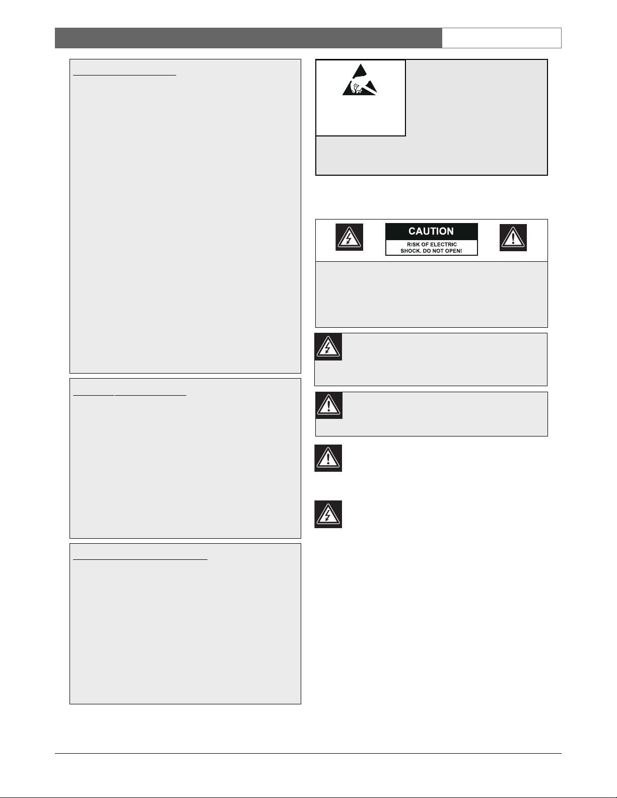
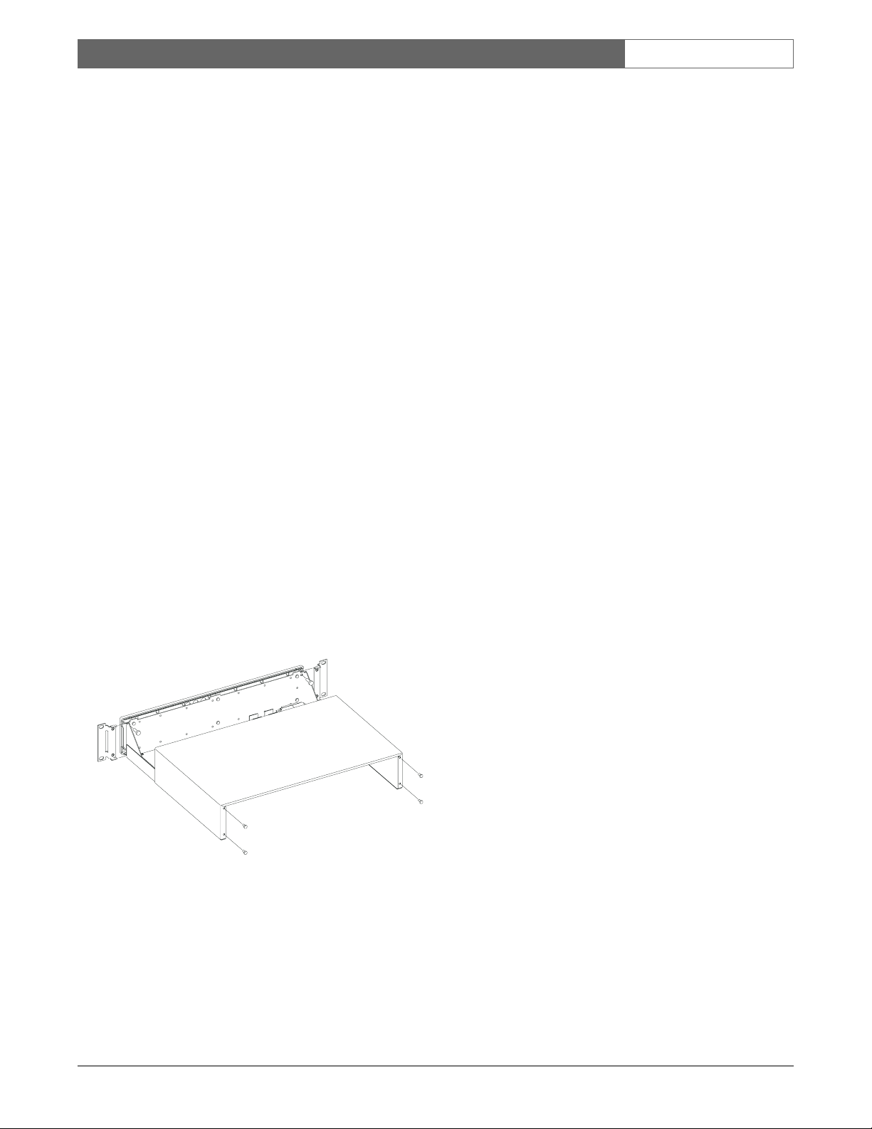
4.2.2 Desk Top Mount
If the unit is not going to be rack mounted, the
enclosure’s mounting ears should be removed. The
cover of the unit must be removed before access to the
mounting ears is possible. Removal of the cover should
only be performed by qualified service personnel. The
unit should always be disconnected from the Allegiant
CPU bay (or alternate power source if one is being
used) before removing the cover.
The top cover is fastened to the case by 4 screws
located on the rear of the unit. Once the screws have
been removed, the cover slides back and off the unit.
Remove each mounting ear by removing the screw
holding the mounting ear to the enclosure chassis.
Refer to the drawing below if needed.
Cover and Rack Ears Removal
4.3 Allegiant CPU Bay Connections
With the power turned “OFF” on the Allegiant series
main CPU bay, install the alarm interface unit in the
rack close enough to the location of the main CPU
bay to allow the supplied cable to be used.
Connect one end of the supplied 9-pin D-type cable
labeled “ALARM” to the rear of the unit and the other
end to the Allegiant main CPU bay connector marked
“ALARM”. Remember to tighten both connector
attachment screws at each connection point. The front
panel LED should light upon application of power to
the main CPU bay.
4.4 Operational Settings
The unit contains internal DIP switches which can be
used to set certain operating characteristics. The lid to
the unit must be removed as described above if the
DIP switches need to be changed from their Factory
default settings. Refer to the LTC 8540/00 table below
for DIP locations. The following tables summarize the
DIP switch settings and their associated features:
LTC 8540/00
1
Denotes Factory default settings.
The unit communicates with the Allegiant main CPU
bay using RS-232. The first three switches of DIP
switch S101 are used to select the desired baud rate.
Refer to the LTC 8540/00 layout diagram below for
locations. Follow the table if a change from the Factory
default setting is required.
Note that the Allegiant CPU bay must also be set to
the same baud rate.
LTC 8540/00
1
Denotes Factory default settings on units starting with serial
No. 1500.
2
Denotes Factory default settings on units below serial No. 1500.
S101 - DIP
Switch No. Function
4 ON for RTS/CTS enabled.
OFF to disable RTS/CTS.
1
S103 - DIP Function
Switch No.
1 ON for alarms 1 to 32 as normally open (NO).
1
OFF for alarms 1 to 32 as normally closed (NC).
2 ON for alarms 33 to 64 as normally open (NO).
1
OFF for alarms 33 to 64 as normally closed (NC).
3 ON for alarm output relays as normally open (NO).
1
OFF for alarm output relays as normally closed
(NC).
4 ON for audible buzzer enabled.
1
OFF to disable audible buzzer.
S101 - DIP Switch No. Baud
1 2 3 Rate
OFF OFF OFF 19200
1
OFF OFF ON 9600
OFF ON OFF 4800
OFFONON2400
ON OFF OFF 1200
2
ON OFF ON 600
ON ON OFF Not Used
ON ON ON Not Used
S929A39AE
Page 9

EN|9
Bosch Security Systems | December 13, 2007
LTC 8540/00 Series | Instruction Manual | Installation
4.5 Alarm Input Connections
Connect any 2 conductor wire (shielded cable not
usually required) between the alarming device (contact
closure or logic level, 0 to 5 VDC) and the appropriate
LTC 8540/00 input. The alarm input numbers are
marked on the rear panel. Note that two alarm inputs
share a common ground connection. The alarm inputs
can be configured in groups of 32 to accept either
normally open (Factory default) or normally closed
type contacts. Refer to the operational settings
information above if changes from the Factory default
settings are necessary. The total wire ‘loop resistance’
should not exceed 1000 ohms. The unit’s input #1
corresponds to camera #1 in the Factory default
setting, but this relationship can be changed during
programming with the optional Allegiant Master
Control Software package.
4.6 Alarm Output Connections
The LTC 8540/00 unit provides eight alarm relay
outputs. An alarm output is typically used to activate
the alarm input of a security type VCR or other
alerting device. A VCR is normally programmed to
change recording speeds from a slower time lapse
mode to a faster real time mode upon alarm activation.
Operation of the eight relay outputs of the
LTC 8540/00 depends upon how the Allegiant system
has been configured to respond to alarm events. The
alarm output relays activate accordingly under the
following conditions:
1. Relay 1 will activate if the base Allegiant system
is set to use the Basic alarm response mode and
an alarm occurs on any system monitor. Relay 1
will deactivate after all alarms have been
removed from the inputs. Relay 1 will also
deactivate if the Allegiant system is disarmed
(either the monitor being disarmed or the
alarm(s) being disarmed) by an operator from
the keyboard. Pressing the Acknowledge key on
the system keyboard will not deactivate Relay 1
since the alarm video follows the contact
applied to the unit in this alarm response mode.
Relays 2 through 8 are not used in this mode.
2. Relay 1 will activate if the base Allegiant system
is set to use the Sequence & Display alarm
response mode and an alarm occurs on any
system monitor. Relay 1 will deactivate after all
alarm videos have been acknowledged (pressing
the keyboard Acknowledge key) by the system
operator(s) from all system monitors. Relay 1
will also deactivate if the Allegiant system is
disarmed (either the monitor being disarmed or
the alarm(s) being disarmed) by an operator
from the keyboard. Removal of the alarm input
will not deactivate Relay 1 since the alarm
video(s) are not dependent upon the duration of
the contact applied to the unit in this alarm
response mode. Relays 2 through 8 are not used
in this mode.
3. If the base Allegiant system is set to use the
Autobuild alarm response mode and an alarm
occurs on system monitors 1 through 8, the
relay corresponding to the monitor number will
activate for the duration that the corresponding
alarm input is applied to the unit. The relay will
deactivate if the monitor associated with the
relay or if the alarm(s) being displayed on the
monitor is disarmed by an operator from the
keyboard. Pressing the Acknowledge key on the
system keyboard will not deactivate the relays
since the alarm video follows the contact
applied to the unit in this alarm response mode.
4. If the VersAlarm™ Group Table screen in the
PC based Master Control Software package
contains an alarm group where Monitors 1
through 8 are included and the ‘Monitor’ option
has been selected in the ‘Relay Action’ column,
the relay corresponding to the monitor number
will activate for the duration that the alarm
video remains on the monitor. The relay will
deactivate if the monitor associated with the
relay or if the alarm(s) being displayed on the
monitor is disarmed by an operator from the
keyboard. Pressing the Acknowledge key on the
system keyboard will not deactivate the relay
unless this feature has been selected for the
associated alarm group. If the ‘Monitor’ option
has been set to ‘1’ in the Group Table, only
Relay 1 will activate when monitors in that
alarm group become alarmed.
Page 10

EN|10
Bosch Security Systems | December 13, 2007
LTC 8540/00 Series | Instruction Manual | Installation
Typically any 2 conductor wire can be used between
the rear panel terminal block containing the unit relay
outputs and the VCR alarm input. If some other
external device is to be controlled, do not exceed the
relay ratings of 10 W, 0.75 A.
4.7 Interface Port Pinouts
Follow the table below if a cable other than the one
supplied with the LTC 8540/00 will be used.
9-Pin Function
1 Chassis Ground
2 Receive
3 Transmit
4CTS
5RTS
6 Data Ground
7 Data Ground
8 12 VAC in or 12 VDC in
9 12 VAC in or 12 VDC in
Page 11
EN|11
Bosch Security Systems | December 13, 2007
LTC 8540/00 Series | Instruction Manual | Illustrations
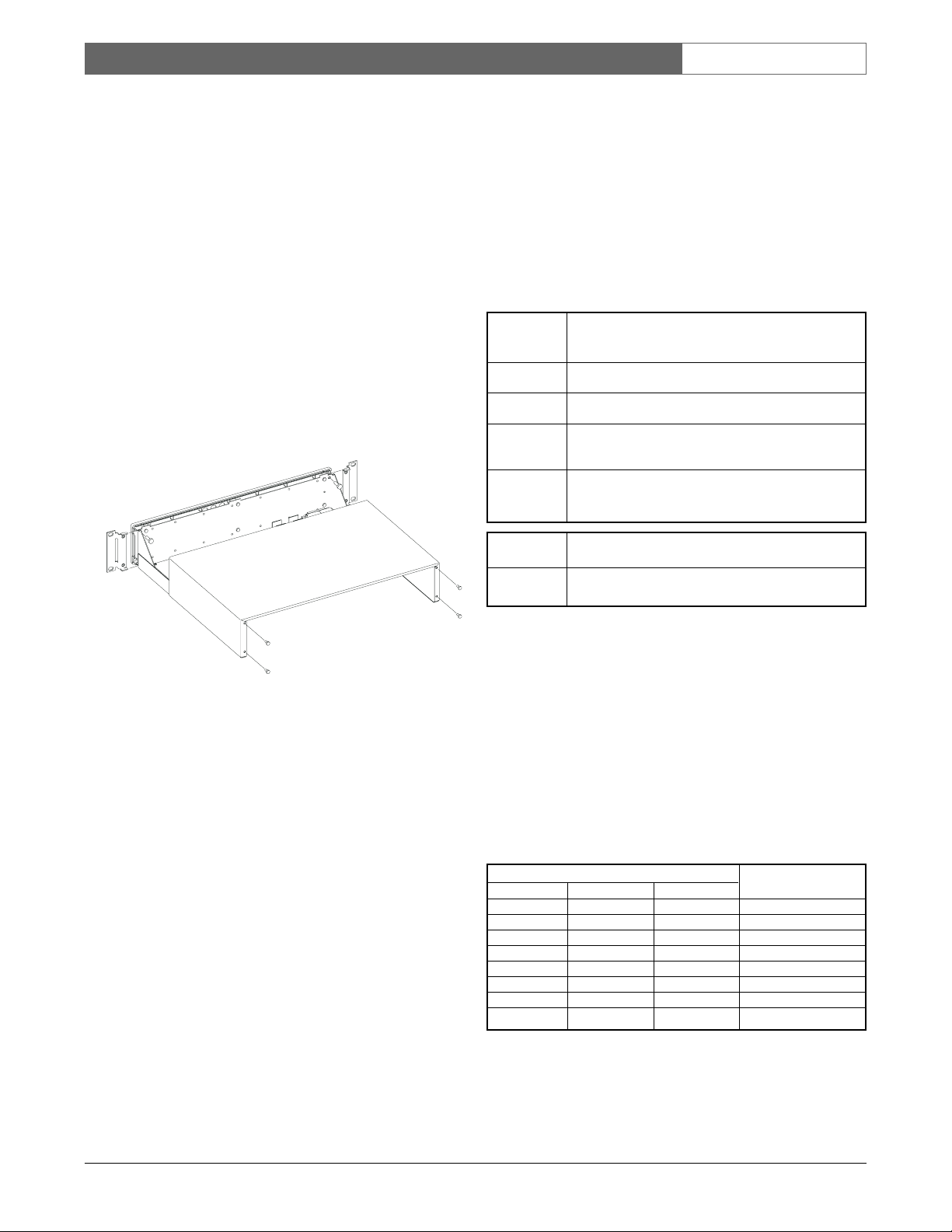
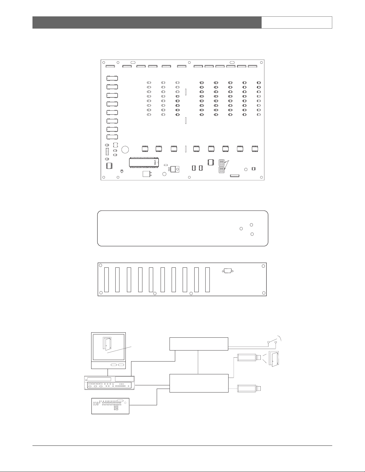
5 ILLUSTRATIONS
LTC 8540/00 Alarm Interface Unit Layout
LTC 8540/00 Front and Rear Panel
Typical LTC 8540/00 Alarm Interface Application
001 12:00:00
MAIN LOBBY DOOR 11 11 90
S103 S101
OFF
ON
DIP
12
SWITCH
3
412
3
4
A8
A16
GND
GND
A7
A15
A6
A14
GND
GND
A5
A13
A4
A12
GND
GND
A3
A11
A2
A10
GND
GND
A1
A9
A32
A24
GND
GND
A31
A23
A30
A22
GND
GND
A29
A21
A28
A20
GND
GND
A27
A19
A26
A18
GND
GND
A25
A17
System Monitor
Flashing On-Screen
Alarm Indicator
VCR
Alarm Input
ALM
001 12:00:00
MAIN LOBBY DOOR 11 11 90
VIDEO CASSETTE RECORDER
Security VCR
ALARM
POWER
Front
A40
GND
A38
A38
GND
A37
A36
GND
A35
A34
GND
A33
GND
GND
A55
A47
A54
A46
GND
GND
A53
A45
A52
A44
GND
GND
A51
A43
A50
A42
GND
GND
A49
A41
R6
GND
A63
A62
GND
A61
A60
GND
A59
A58
GND
A57
12 V
R5
R5
R4
R4
R3
R3
R8
R2
R8
R2
R7
R1
R7
R1
RS232
12 V
R6
A64
A56
A48
Rear
LTC 8540/00 Alarm
Interface Unit
Alarm
Output
Relay
Main CPU Equipment Bay
RS-232
Alarm
Data
Allegiant Series
Switcher/Controller
Door Alarm
Contact
Typical
System
Cameras
S9405014AE
System Keyboard
Page 12

LTC 8540/00 Série | Instructions d’installation | Consignes de Sécurité Importants
FR
|
12
Bosch Security Systems | December 13, 2007
Consignes de Sécurité Importantes
1. Lisez, observez et conservez les instructions
ci après - Lisez et observez scrupuleusement
l'ensemble des instructions de sécurité et d'utilisation
avant d'employer l'appareil, et conservez-les pour
référence ultérieure.
2. Respectez les avertissements - Respectez les
différents avertissements repris sur l'appareil et
dans les instructions d'utilisation.
3. Fixations - Utilisez exclusivement les fixations
recommandées par le fabricant, au risque d'exposer
les utilisateurs à des situations potentiellement
dangereuses.
4. Mises en garde relatives à l'installation - Évitez de
placer l'appareil sur un pied, un trépied, un support ou
une monture instable. L'appareil risque de tomber, de
provoquer des lésions corporelles graves et de subir
des dégâts importants. Utilisez exclusivement les
accessoires recommandés par le fabricant ou fournis
avec l'appareil. Installez l'appareil conformément aux
instructions du fabricant. Si vous utilisez un chariot
pour déplacer l'appareil, manipulez le chariot avec
précaution. Les arrêts brusques, les forces excessives
et les surfaces inégales risquent d'entraîner le
renversement du chariot et de l'appareil.
5. Nettoyage - Avant de nettoyer l'appareil, débranchezle de la prise de courant. Observez les instructions
fournies avec l'appareil. En règle générale, l'utilisation
d'un chiffon humide suffit pour nettoyer l'appareil.
Évitez l'emploi de nettoyants liquides ou aérosol.
6. Réparation - N'essayez pas de réparer vous-même
l'appareil : l'ouverture et le retrait des capots présente
un risque d'électrocution et d'autres dangers. Confiez
la réparation de l'appareil à du personnel qualifié.
7. Dégâts nécessitant réparation - Débranchez
l'appareil de la prise de courant et confiez la réparation
à du personnel qualifié dans les cas suivants :
• Détérioration du cordon ou de la fiche
d’alimentation ;
• Infiltration de liquide ou introduction d'objets
dans l'appareil ;
• Exposition de l'appareil à l'eau ou aux intempéries
(pluie, neige, etc.) ;
• Fonctionnement anormal de l'appareil, malgré
l'observation des instructions d'utilisation. Procédez
uniquement au réglage des commandes tel
qu'indiqué dans les instructions d'utilisation. Tout
autre réglage risque d'endommager l'appareil et
implique généralement d'importants travaux de
réparation par un technicien qualifié ;
• Chute de l'appareil ou dégâts au niveau du
boîtier ;
• Constatation d'une modification au niveau des
performances de l'appareil.
8. Pièces de rechange - En cas de remplacement de
pièces, veillez à ce que le technicien utilise des
pièces recommandées par le fabricant ou des pièces
présentant les mêmes caractéristiques que les pièces
d'origine. L'utilisation de pièces non homologuées
présente un risque d'incendie, d'électrocution et
d'autres dangers.
9. Contrôle de sécurité - Une fois les travaux d'entretien
ou de réparation terminés, demandez au technicien de
procéder à un contrôle de sécurité pour vérifier si
l'appareil est en parfait état de marche.
10. Alimentation - Utilisez exclusivement le type
d'alimentation indiqué sur l'étiquette. En cas de doute
sur le type d'alimentation à utiliser, consultez votre
revendeur ou votre fournisseur d'électricité local.
• Pour les modèles nécessitant une pile,
reportez-vous aux instructions d'utilisation.
• Pour les modèles nécessitant une alimentation
externe, utilisez exclusivement les sources
d'alimentation homologuées recommandées.
• Pour les modèles nécessitant une source
d'alimentation limitée, utilisez une source
d'alimentation conforme à la norme EN60950.
L'utilisation d'autres types de source d'alimentation
risque d'endommager l'appareil, voire de
provoquer un incendie ou une électrocution.
• Pour les modèles nécessitant une alimentation
24 Vca, utilisez une tension d'entrée standard de
24 Vca. La tension appliquée à l'entrée
d'alimentation de l'appareil ne peut dépasser
30 Vca. Le câblage fourni par l'utilisateur,
de l'alimentation 24 Vca vers l'appareil, doit être
conforme aux codes d'électricité en vigueur
(niveaux de puissance de classe 2). L'alimentation
24 Vca des bornes et des bornes d'alimentation de
l'appareil ne doit pas être mise à la terre.
11. Mise à la terre du câble coaxial - Si vous connectez
un système de câblage externe à l'appareil, assurez-vous
que ce système de câblage est mis à la terre. Modèles
américains uniquement : la section 810 du code
national d'électricité américain (NEC), ANSI/ NFPA
n° 70, fournit des informations sur la mise à la terre de
la monture et de la structure portante, la mise à la terre
du câble coaxial vers un dispositif de décharge, la taille
des conducteurs de terre, l'emplacement du dispositif
de décharge, la connexion aux électrodes de terre et les
exigences relatives aux électrodes de terre.
12. Mise à la terre ou polarisation - Cet appareil peut
être équipé d'une fiche polarisée de courant alternatif
(fiche présentant une broche plus large que l'autre).
Grâce à ce dispositif de sécurité, la fiche ne s'insère
dans la prise que dans un sens. Si la fiche n'entre pas
complètement dans la prise, retournez la fiche. Si le
problème persiste, demandez à un électricien de
remplacer la prise. Ne retirez en aucun cas le
dispositif de sécurité de la fiche polarisée.
Cet appareil peut également être équipé d'une fiche de
terre 3 fils (fiche présentant une troisième broche,
destinée à la mise à la terre). Grâce à ce dispositif de
sécurité, la fiche ne s'insère que dans une prise de
terre. Si la fiche n'entre pas dans la prise, demandez à
un électricien de remplacer la prise. Ne retirez en
aucun cas le dispositif de sécurité de la fiche de terre.
13. Orage - Pour davantage de protection en cas d'orage,
ou si vous n'avez pas l'intention d'utiliser l'appareil
pendant une période prolongée, débranchez l'appareil
de la prise murale et déconnectez le système de
câblage. Cette opération permet d'éviter les dégâts au
niveau de l'appareil en cas d'orage ou de surtension
des lignes électriques.
Page 13
LTC 8540/00 Série | Instructions d’installation | Consignes de Sécurité Importa
FR
|
13
Bosch Security Systems | December 13, 2007
Modèle Destiné Aux Applications
D'intérieur
1. Eau et humidité - Évitez d'utiliser l'appareil à
proximité d’un point d'eau, par exemple dans une
cave humide, dans une installation d'extérieur non
protégée ou à tout autre endroit exposé à l'humidité.
2. Infiltration de liquide ou introduction d'objets -
N'introduisez aucun objet dans les orifices de
l'appareil. Ces objets risquent d'entrer en contact
avec des points de tension dangereuse, d'entraîner
le court-circuit de certains composants et de
provoquer un incendie ou une électrocution.
Évitez de renverser des substances liquides sur
l'appareil.
3. Cordon d'alimentation et protection du
cordon d'alimentation - Pour les modèles
nécessitant une alimentation 230 Vca, 50 Hz,
utilisez un cordon d'alimentation d'entrée et de
sortie conforme aux exigences imposées par la
dernière version de la publication IEC 227 ou 245.
Acheminez les cordons d'alimentation de sorte
qu'ils ne soient ni piétinés ni comprimés. Portez
une attention particulière à l'emplacement des
cordons, des fiches, des prises de courant et du
point de sortie de l'appareil.
4.Surcharge - Pour éviter tout risque d'incendie ou
d'électrocution, ne surchargez pas les prises de
courant ni les rallonges.
Modèle Destiné Aux Applications
D'extérieur
Lignes électriques - Évitez de placer les systèmes
extérieurs à proximité de lignes électriques
aériennes, de systèmes d'éclairage électrique, de
circuits électriques, ou à un endroit où ils risquent
d'entrer en contact avec de tels dispositifs. Lors de
l'installation d'un système d'extérieur, évitez de
toucher les lignes et les circuits électriques : un tel
contact peut être fatal. Modèles américains
uniquement : consultez l’article 820 du code
national d’électricité américain (NEC) relatif à
l’installation des systèmes de câblodistribution
(CATV).
Modèle Dest
iné Au Montage En Bâti
1. Ventilation - Évitez de placer l'appareil dans un
bâti ou dans une installation intégrée, sauf si la
ventilation s'y effectue correctement ou si le
fabricant préconise une telle disposition. La
température de fonctionnement de l'appareil ne
peut dépasser la valeur maximale indiquée.
2. Chargement mécanique - Le montage de
l'appareil en bâti doit être exempt de tout risque
d'accident lié à un chargement mécanique
irrégulier.
AVERTISSEMENT :
cet appareil est sensible aux décharges
électrostatiques. Pour éviter tout risque
de décharge électrostatique, observez
les précautions de manipulation du
CMOS/MOSFET appropriées.
REMARQUE : lors de la manipulation des cartes à circuits
imprimés sensibles aux décharges électrostatiques, portez des
bracelets antistatiques mis à la terre et observez les consignes de
sécurité relatives aux décharges électrostatiques.
ATTENTION
Observez les précautions de
manipulation des appareils
sensibles aux décharges
électrostatiques.
Sécurité
Attention : l'installation doit exclusivement être réalisée par du
personnel qualifié, conformément au code national d'électricité
américain (NEC) ou au code d'électricité local en vigueur.
Coupure de l'alimentation. Qu'ils soient pourvus ou non d'un
commutateur ON/OFF, tous les appareils reçoivent de l'énergie une
fois le cordon branché sur la source d'alimentation. Toutefois,
l'appareil ne fonctionne réellement que lorsque
le commutateur est réglé sur ON. Le débranchement du cordon
d'alimentation permet de couper l'alimentation des appareils.
ATTENTION : POUR ÉVITER TOUT RISQUE D'ÉLECTROCUTION,
N'ESSAYEZ PAS DE RETIRER LE CAPOT (OU LE PANNEAU
ARRIÈRE). CET APPAREIL NE CONTIENT AUCUN COMPOSANT
SUSCEPTIBLE D'ÊTRE RÉPARÉ PAR L'UTILISATEUR. CONFIEZ
LA RÉPARATION DE L'APPAREIL À DU PERSONNEL QUALIFIÉ.
Ce symbole signale que le produit renferme une « tension
potentiellement dangereuse » non isolée susceptible de
provoquer une électrocution.
Ce symbole invite l'utilisateur à consulter les instructions
d'utilisation et d'entretien (dépannage) reprises dans la
documentation qui accompagne l'appareil.
Page 14

FR|14
Bosch Security Systems | December 13, 2007
LTC 8540/00 Série | Instructions d’installation | Informations FCC et ICES
INFORMATIONS FCC ET ICES
(modèles utilisés aux États-Unis et au Canada uniquement)
Cet appareil est conforme aux exigences imposées par la section 15
du règlement de la Commission fédérale des communications des
États-Unis (FCC). Son utilisation est soumise aux deux conditions
suivantes :
(1) Cet appareil ne doit pas provoquer
d'interférences nuisibles, et
(2) doit supporter toutes les interférences reçues, dont les
interférences susceptibles d'entraîner un fonctionnement
imprévu.
REMARQUE : suite à différents tests, cet appareil s'est révélé
conforme aux exigences imposées aux appareils numériques de
classe B, en vertu de la section 15 du règlement de la Commission
fédérale des communications des États-Unis (FCC), et en vertu de
la norme ICES-003 d'Industrie Canada. Ces exigences visent à
fournir une protection raisonnable contre les interférences nuisibles
lorsque l'appareil est utilisé dans le cadre d'une installation
résidentielle. Cet appareil génère, utilise et émet de l'énergie de
radiofréquences et peut, en cas d'installation ou d'utilisation non
conforme aux instructions, engendrer des interférences nuisibles au
niveau des radiocommunications. Toutefois, rien ne garantit
l'absence d'interférences dans une installation particulière. Il est
possible de déterminer la production d'interférences en mettant
l'appareil successivement hors et sous tension, tout en contrôlant la
réception radio ou télévision. L'utilisateur peut parvenir à éliminer
les interférences éventuelles en prenant une ou plusieurs des
mesures suivantes :
• Modifier l'orientation ou l'emplacement de
l'antenne réceptrice ;
• Éloigner l'appareil du récepteur ;
• Brancher l'appareil sur une prise située sur un circuit différent
de celui du récepteur ;
• Consulter le revendeur ou un technicien qualifié en
radio/télévision pour obtenir de l'aide.
Toute modification apportée au produit, non expressément
approuvée par la partie responsable de l'appareil, est strictement
interdite. Une telle modification est susceptible d'entraîner la
révocation du droit d'utilisation de l'appareil.
La brochure suivante, publiée par la Commission fédérale des
communications (FCC), peut s'avérer utile : « How to Identify and
Resolve Radio-TV Interference Problems ». Cette brochure est
disponible auprès du U.S. Government Printing Office,
Washington, DC 20402, États-Unis, sous la référence
n° 004-000-00345-4.
Page 15

FR|15
Bosch Security Systems | December 13, 2007
LTC 8540/00 Série | Instructions d’installation | Sommaire
SOMMAIRE
1 DEBALLAGE . . . . . . . . . . . . . . . . . . . . . . . . . . . . . . . . . . . . . . . . . . . . . . . . . . . . . . . . . . . . . . . . .16
2 SERVICE . . . . . . . . . . . . . . . . . . . . . . . . . . . . . . . . . . . . . . . . . . . . . . . . . . . . . . . . . . . . . . . . . . . .16
3 DESCRIPTION . . . . . . . . . . . . . . . . . . . . . . . . . . . . . . . . . . . . . . . . . . . . . . . . . . . . . . . . . . . . . . .16
4 INSTALLATION . . . . . . . . . . . . . . . . . . . . . . . . . . . . . . . . . . . . . . . . . . . . . . . . . . . . . . . . . . . . . .16
4.1 Alimentation/Données . . . . . . . . . . . . . . . . . . . . . . . . . . . . . . . . . . . . . . . . . . . . . . . . . . . . . . . . . .16
4.2 Options de montage . . . . . . . . . . . . . . . . . . . . . . . . . . . . . . . . . . . . . . . . . . . . . . . . . . . . . . . . . . . .17
4.3 Connexions de la baie du processeur central Allegiant . . . . . . . . . . . . . . . . . . . . . . . . . . . . . . . . . .17
4.4 Réglages opérationnels . . . . . . . . . . . . . . . . . . . . . . . . . . . . . . . . . . . . . . . . . . . . . . . . . . . . . . . . . . .17
4.5 Connexions d’entrée d’alarme . . . . . . . . . . . . . . . . . . . . . . . . . . . . . . . . . . . . . . . . . . . . . . . . . . . . .18
4.6 Connexions de sortie d’alarme . . . . . . . . . . . . . . . . . . . . . . . . . . . . . . . . . . . . . . . . . . . . . . . . . . . .18
4.7 Brochage du port d’interface . . . . . . . . . . . . . . . . . . . . . . . . . . . . . . . . . . . . . . . . . . . . . . . . . . . . . .19
5 ILLUSTRATIONS . . . . . . . . . . . . . . . . . . . . . . . . . . . . . . . . . . . . . . . . . . . . . . . . . . . . . . . . . . . . .20
Page 16

FR|16
Bosch Security Systems | December 13, 2007
LTC 8540/00 Série | Instructions d’installation | Deballage
1 DEBALLAGE
Veuillez procéder avec précaution lors du déballage.
Ce matériel est de type électronique et il doit être
manipulé avec soin.
Veuillez contrôler la présence des éléments suivants:
• Le numéro de modèle de l’appareil
• Un (1) cable avec un connecteur DB9
• Kit de connecteurs, contient 10 connecteurs
12 broches
• Manuel d'installation
Si un élément semble avoir été endommagé durant le
transport, veuillez le remettre correctement dans son
carton et en informer le transporteur. Si un ou
plusieurs éléments sont manquants, veuillez en
informer le représentant commercial ou le bureau
d’assistance à la clientèle de Bosch Security Systems.
Le carton d’emballage d’origine constitue le meilleur
moyen d’emballage pour le transport de l’appareil.
Conservez-le à des fins d’utilisation ultérieure.
2 SERVICE
Si l’appareil a besoin d’être réparé, le client est invité à
contacter le Centre Technique de Bosch Security
Systems, Inc.. le plus proche afin d’obtenir une
autorisation de retour et des instructions d’expédition.
Centres d’entretien
États-Unis
Tél. : 800-366-2283 ou 585-340-4162
Fax : 800-366-1329
Email : cctv.repair@us.bosch.com
Assistance technique
Tél. : 800-326-1450
E-mail : technical.support@us.bosch.com
Pièces de rechange vidéosurveillance
Tél. : 800-894-5215 ou 408-957-3065
Fax : 408-935-5938
E-mail : BoschCCTVparts@ca.slr.com
Canada
Tél. : 514-738-2434
Fax : +514-738-8480
Europe, Moyen-Orient et région Asie-Pacifique
Tél. : 44 (0) 1495 274558
Fax : 44 (0) 1495 274280
E-mail : rmahelpdesk@solectron.com
Pour de plus amples informations, visitez le site
www.boschsecurity.fr
3 DESCRIPTION
Le module d’interface d’alarme LTC 8540/00 permet
aux commutateurs/contrôleurs matriciels de la série
Allegiant® (LTC 8500, LTC 8600, TC8700 et
LTC 8800) d’afficher automatiquement le signal vidéo
lorsque des conditions d’alarme se produisent. Le
LTC 8540/00 accepte jusqu’à 64 fermetures de contact
ou entrées de niveau logique en provenance de
dispositifs de détection distants, comme des contacts de
porte, des détecteurs passifs à infrarouge, etc., et il
retransmet alors l’information d’alarme à la baie du
processeur central de la série Allegiant. Les entrées
d’alarme peuvent être configurées par groupes de 32
afin d’accepter des contacts soit normalement ouverts,
soit normalement fermés. Le module LTC 8540/00
dispose également de huit sorties à fermeture de relais
lorsque des conditions d’alarme se produisent.
4 INSTALLATION
4.1 Alimentation/Données
Il est fourni un câble d’interface pour alimentation et
données afin de permettre le raccordement entre le
module LTC 8540/00 et la baie du processeur central
Allegiant. Le cas échéant, l'unité d'interface d'alarmes
peut être installée à distance avec une alimentation 8
W, 12 Vca ou 12 Vcc, homologuée classe 2 ou
équivalent, fournie par l'utilisateur. Une ligne
d’interface RS-232 comportant au minimum 3 ou 5 fils
est alors nécessaire pour assurer la communication
avec la baie du processeur central Allegiant. Si
nécessaire, le câble fourni peut être coupé et raccordé
pour réaliser les connexions appropriées. Il est
proposé à la fin de ce manuel une table indiquant le
brochage du port d’interface du module. Le brochage
du port Allegiant est indiqué dans la section TABLE
DE RÉFÉRENCE RAPIDE DU BROCHAGE DES
CONNECTEURS DU PANNEAU ARRIÈRE DE
LA BAIE CENTRALE des Instructions d’installation
et d’utilisation de la série Allegiant.
Attention: Ne raccordez jamais une
alimentation électrique externe à ce module s’il
est déjà connecté à la baie du processeur central
Allegiant par l’intermédiaire du câble fourni.
Page 17
FR|17
Bosch Security Systems | December 13, 2007
LTC 8540/00 Série | Instructions d’installation | Installation
4.2 Options de montage
4.2.1 Montage en châssis
Le module LTC 8540/00 est livré d’usine dans un
boîtier adapté au montage en châssis. Le boîtier est au
format EIA, large d’une unité et haut de deux unités.
Décollez les quatre pieds en caoutchouc se trouvant
sous le boîtier avant de l’installer dans la console.
4.2.2 Montage sur dessus de bureau
Si le module n’est pas destiné à être installé en châssis,
il est nécessaire d’en retirer les pattes de montage. Le
couvercle de l’appareil doit être retiré afin de pouvoir
accéder aux pattes de montage.Le retrait du couvercle
ne doit être effectué que par un personnel technique
qualifié. Le module doit toujours être déconnecté de la
baie du processeur central Allegiant (ou de la source
électrique externe, le cas échéant) avant de procéder
au retrait du couvercle.
Le couvercle supérieur est fixé au boîtier par quatre vis
situées à l’arrière de l’appareil. Après que les vis aient
été retirées, il est possible de faire coulisser le
couvercle vers l’arrière et de le dégager. Retirez
chacune des pattes de fixation en retirant la vis
maintenant la patte de fixation au châssis du boîtier. Si
nécessaire, veuillez vous référer au schéma proposé
ci-dessous.
Retrait du couvercle et des pattes pour châssis
4.3 Connexions de la baie du
processeur central Allegiant
L’alimentation de la baie du processeur central
Allegiant étant interrompue (“OFF”), installez le
module d’interface d’alarme dans le châssis à
proximité suffisante de l’emplacement de la baie du
processeur central afin de permettre l’utilisation du
câble fourni.
Raccordez une extrémité du câble de type D à 9
broches marqué “ALARM” à l’arrière du module et
l’autre extrémité au connecteur de la baie du
processeur central Allegiant marqué “ALARM”.
Veillez à bien serrer les vis de fixation des connecteurs
à chaque point de connexion. Le témoin LED du
panneau avant doit s’allumer lorsque la baie du
processeur central est mise sous tension.
4.4 Réglages opérationnels
Le module contient des interrupteurs DIP internes qui
peuvent être utilisés pour définir certaines
caractéristiques opérationnelles. Le couvercle de
l’appareil doit être retiré de la manière décrite
ci-dessus si les réglages d’usine par défaut des
interrupteurs DIP doivent être modifiés. Veuillez vous
référer à la table LTC 8540/00 ci-dessous pour
connaître la position des interrupteurs DIP. Les tables
suivantes contiennent un récapitulatif des réglages des
interrupteurs DIP et des fonctions qui leur sont
associées:
S929A39AE
Page 18

FR|18
Bosch Security Systems | December 13, 2007
LTC 8540/00 Série | Instructions d’installation | Installation
LTC 8540/00
1
Indique le réglage d’usine par défaut.
Le module communique avec la baie du processeur
central Allegiant par l’intermédiaire d’une liaison RS-
232. Les trois premiers interrupteurs DIP de la barrette
S101 sont utilisés pour sélectionner le taux de baud
souhaité. Veuillez vous référer au schéma
d’implantation LTC 8540/00 proposé ci-dessous pour
connaître les emplacements des interrupteurs DIP.
Veuillez utiliser l’information contenue dans la table s’il
s’avère nécessaire de modifier un réglage d’usine par
défaut.
Veuillez noter qu’il faut que la baie du processeur
central Allegiant soit également configurée pour le
même taux de baud.
LTC 8540/00
1
Indique un réglage d’usine par défaut sur les appareils dont le
numéro de série est égal ou supérieur à 1500.
2
Indique un réglage d’usine par défaut sur les appareils dont le
numéro de série est inférieur à 1500.
4.5 Connexions d’entrée d’alarme
Connectez tout câble à 2 conducteurs (un câble blindé
n’est habituellement pas nécessaire) entre le dispositif
de détection (fermeture de contacts ou niveau logique,
0 à 5 Vcc) et l’entrée appropriée du module
LTC 8540/00. Les numéros d’entrée d’alarme sont
marqués sur le panneau arrière. Veuillez noter que
deux entrées d’alarme se partagent une connexion
commune de masse. Les entrées d’alarme peuvent être
configurées par groupes de 32 pour accepter des
contacts de type normalement ouvert (réglage d’usine
par défaut) ou normalement fermé. Veuillez vous
référer à l’information concernant les réglages
opérationnels proposée ci-dessus s’il s’avère nécessaire
de modifier les réglages d’usine par défaut. La
résistance totale de la “boucle” de câble ne doit pas
dépasser 1000 ohms. L’entrée #1 du module
correspond à la caméra #1 selon le réglage d’usine par
défaut, mais cette relation peut être changée durant la
programmation en utilisant le logiciel optionnel
“Master Control” de la série Allegiant.
4.6 Connexions de sortie d’alarme
Le module LTC 8540/00 comporte huit sorties de
relais d’alarme. Une telle sortie d’alarme est
habituellement utilisée pour activer l’entrée d’alarme
d’un dispositif de type magnétoscope ou avertisseur
d’alarme. Le magnétoscope est normalement
programmé de manière à changer de vitesse
d’enregistrement et passer d’un mode à prise de vue
lente à un mode plus rapide de prise de vue en temps
réel lors de l’activation de l’alarme.
Le fonctionnement des huit sorties de relais dépend de
la manière dont le système Allegiant a été configuré
pour répondre aux événements d’alarme. Les relais de
sortie d’alarme s’activent en conséquence lors des
conditions suivantes:
1. Le relais 1 s’active si le système de base
Allegiant est configuré pour utiliser le mode de
réponse d’alarme Basic et qu’une alarme se
produit sur un moniteur quelconque du
système. Le relais 1 se désactive après que
toutes les alarmes aient été retirées des entrées.
Le relais 1 se désactive également si le système
Allegiant est désarmé (soit que le moniteur ait
été désarmé, soit que la ou les alarmes aient été
désarmées) par un opérateur à partir du clavier.
L’appui de la touche “Acknowledge”
(Acquittement) du clavier du système ne
DIP S103
Interrupt. # Fonction
1 ON pour les alarmes 1 à 32 configurées
comme normalement ouvertes (NO).
1
OFF pour les alarmes 1 à 32 configurées
comme normalement fermées (NF).
2 ON pour les alarmes 33 à 64 configurées
comme normalement ouvertes (NO).
1
OFF pour les alarmes 33 à 64 configurées
comme normalement fermées (NF).
3 ON pour les relais de sortie d’alarme
configurés comme normalement ouverts (NO).
1
OFF pour les relais de sortie d’alarme
configurés comme normalement fermés (NF).
4 ON pour activer le signal sonore d’avertissement.
1
OFF pour désactiver le signal sonore
d’avertissement.
DIP S101
Interrupt. # Fonction
4 ON pour activer RTS/CTS.
OFF pour désactiver RTS/CTS.
1
DIP S101 : Interrupt. # Taux de
1 2 3 baud
OFF OFF OFF 19200
1
OFF OFF ON 9600
OFF ON OFF 4800
OFFONON2400
ON OFF OFF 1200
2
ON OFF ON 600
ON ON OFF Non utilisé
ON ON ON Non utilisé
Page 19

FR|19
Bosch Security Systems | December 13, 2007
LTC 8540/00 Série | Instructions d’installation | Installation
désactive pas le relais 1, car le signal vidéo
correspondant à l’alarme suit le contact appliqué
à l’appareil dans ce mode de réponse d’alarme.
Les relais 2 à 8 ne sont pas utilisés dans ce
mode.
2. Le relais 1 s’active si le système de base
Allegiant est configuré pour utiliser le mode de
réponse d’alarme “Sequence & Display” et
qu’une alarme se produit sur un moniteur
quelconque du système. Le relais 1 se désactive
lorsque toutes les signaux vidéo correspondant
aux alarmes ont été acquittés (en appuyant sur
la touche “Acknowledge” du clavier) par le ou
les opérateurs du système sur tous les moniteurs
du système. Le relais 1 se désactive également si
le système Allegiant est désarmé (soit que le
moniteur ait été désarmé, soit que la ou les
alarmes aient été désarmées) par un opérateur à
partir du clavier. Le retrait de l’entrée d’alarme
ne désactive pas le relais 1, car le ou les signaux
vidéo correspondant aux alarmes ne dépendent
pas de la durée du contact appliqué à l’appareil
dans ce mode de réponde d’alarme. Les relais 2
à 8 ne sont pas utilisés dans ce mode.
3. Le relais 1 s’active si le système de base
Allegiant est configuré pour utiliser le mode de
réponse d’alarme “Auto-Build” et qu’une alarme
se produit sur l’un des moniteurs 1 à 8 du
système, le relais correspondant au numéro du
moniteur étant activé tant que l’entrée d’alarme
correspondante est appliquée à l’appareil. Le
relais se désactive si le moniteur associé au
relais ou si la ou les alarmes affichées sur le
moniteur sont désarmés par un opérateur à
partir du clavier. L’appui de la touche
“Acknowledge” (Acquittement) du clavier du
système ne désactive pas les relais, car le signal
vidéo correspondant à l’alarme suit le contact
appliqué à l’appareil dans ce mode de réponse
d’alarme.
4. Si l’écran “Group Table” du mode VersAlarm™
du logiciel “Master Control” basé sur PC
contient un groupe d’alarmes dans lequel les
moniteurs 1 à 8 sont inclus et l’option
“Monitor” a été sélectionnée dans la colonne
“Relay Action”, le relais correspondant au
numéro du moniteur s’active tant que le signal
vidéo correspondant à l’alarme reste affiché sur
le moniteur. Le relais se désactive si le moniteur
associé au relais ou si la ou les alarmes affichées
sur le moniteur sont désarmés par un opérateur
à partir du clavier. L’appui de la touche
“Acknowledge” (Acquittement) du clavier du
système ne désactive pas le relais, à moins que
cette option n’ait été sélectionnée pour le
groupe d’alarmes correspondant. Si l’option
“Moniteur” a été réglée sur “1” dans le “Group
Table”, seul le moniteur 1 s’active lorsque les
moniteurs se trouvant dans ce groupe d’alarmes
reçoivent un signal d’alarme.
De manière habituelle, tout fil à deux conducteurs peut
être utilisé entre le bornier du panneau arrière
contenant les sorties des relais et l’entrée d’alarme du
magnétoscope. Si un autre dispositif externe d’alarme
doit être contrôlé, veillez à ne pas dépasser les
caractéristiques nominales du relais, qui sont de
10 W et de 0,75 A.
4.7 Brochage du port d’interface
Veuillez respecter les indications de la table ci-dessous
si vous utilisez un câble autre que celui fourni avec le
module LTC 8540/00.
9 broches Fonction
1 Masse du châssis
2Rx
3Tx
4CTS
5RTS
6 Masse des données
7 Masse des données
8 Entrée 12 Vca ou 12 Vcc
9 Entrée 12 Vca ou 12 Vcc
Page 20

FR|20
Bosch Security Systems | December 13, 2007
LTC 8540/00 Série | Instructions d’installation | Illustrations`
5 ILLUSTRATIONS
Schéma d’implantation du module d’interface d’alarme LTC 8540/00
Panneaux avant et arrière du module LTC 8540/00
Exemple type d’application de l’interface d’alarme LTC 8540/00
001 12:00:00
MAIN LOBBY DOOR 11 11 90
S103 S101
OFF
ON
DIP
12
SWITCH
3
412
3
4
A8
GND
A7
A6
GND
A5
A4
GND
A3
A2
GND
A1
A24
A16
GND
GND
A23
A15
A22
A14
GND
GND
A21
A13
A20
A12
GND
GND
A19
A11
A18
A10
GND
GND
A17
A9
A40
A32
GND
GND
A38
A31
A38
A30
GND
GND
A37
A29
A36
A28
GND
GND
A35
A27
A34
A26
GND
GND
A33
A25
System Monitor
Flashing On-Screen
ALM
001 12:00:00
MAIN LOBBY DOOR 11 11 90
VIDEO CASSETTE RECORDER
Security VCR
Alarm Indicator
VCR
Alarm Input
Front
A56
A48
GND
GND
A55
A47
A54
A46
GND
GND
A53
A45
A52
A44
GND
GND
A51
A43
A50
A42
GND
GND
A49
A41
Rear
LTC 8540/00 Alarm
Alarm
Output
Relay
Main CPU Equipment Bay
R6
A64
R6
GND
R5
A63
R5
A62
R4
GND
A61
R4
A60
R3
GND
R3
A59
R2
A58
R2
GND
R1
A57
R1
Interface Unit
RS-232
Alarm
Data
Allegiant Series
Switcher/Controller
ALARM
POWER
RS232
12 V
12 V
R8
R8
R7
R7
Door Alarm
Contact
Typical
System
Cameras
S9405014AE
System Keyboard
Page 21

LTC 8540/00 Série | Instructions d’installation |
FR
|
21
Bosch Security Systems | December 13, 2007
Page 22

LTC 8540/00 Serie |
Installationsanleitungen
| Wichtige Sicherheitshinweise
DE
|
22
Bosch Security Systems | December 13, 2007
Wichtige Sicherheitshinweise
1. Anweisungen lesen, befolgen und aufbewahren - Alle
Sicherheits- und Bedienungsanweisungen sind vor der
Inbetriebnahme des Geräts zu lesen und zu befolgen. Die
Anweisungen sind für zukünftiges Nachschlagen aufzubewahren.
2. Warnhinweise beachten - Alle Warnhinweise am Gerät und in
der Bedienungsanleitung beachten.
3. Zusatzgeräte - Verwenden Sie keine Zusatzgeräte, die nicht
vom Produkthersteller empfohlen werden, da sonst Gefahren
auftreten können.
4. Installationshinweise - Bringen Sie dieses Gerät nicht auf einer
instabilen Halterung, einem Stativ oder Ähnlichem an. Das
Gerät kann sonst zu Boden fallen und so den Benutzer
ernsthaft verletzen oder selbst beschädigt werden. Verwenden
Sie ausschließlich vom Hersteller empfohlene bzw. die im
Lieferumfang des Geräts enthaltenen Zubehörteile. Befestigen
Sie das Gerät entsprechend den Anweisungen vom Hersteller.
Das Gerät auf einem Wagen darf nur mit äußerster Sorgfalt
bewegt werden. Durch unvermitteltes Anhalten, extreme
Krafteinwirkung und unebene Oberflächen werden das Gerät
und der Wagen möglicherweise zum Umstürzen gebracht.
5. Reinigen - Ziehen Sie den Netzstecker des Geräts aus der
Steckdose, bevor Sie es reinigen. Befolgen Sie sämtliche
Anweisungen zum Gerät. Normalerweise ist das Reinigen mit
einen feuchtes Tuch ausreichend. Verwenden Sie keine
flüssigen Reiniger oder Reiniger in Sprühdosen.
6. Wartung - Versuchen Sie nicht, das Gerät selbst zu warten.
Durch Öffnen oder Entfernen von Abdeckungen können Sie
hohen elektrischen Spannungen oder anderen Gefahren
ausgesetzt sein. Lassen Sie Wartungsarbeiten nur von
qualifiziertem Wartungspersonal ausführen.
7. Im Fall von Beschädigungen, bei denen eine Wartung
erforderlich ist - Ziehen Sie den Netzstecker aus der Steckdose,
und überlassen Sie das Gerät qualifiziertem Personal zur
Wartung, wenn eine der folgenden Bedingungen eintritt:
• Das Netzkabel oder der Netzstecker ist beschädigt.
• Flüssigkeit oder Fremdkörper sind in das Gerät gelangt.
• Das Gerät ist mit Wasser in Kontakt gekommen und/oder
wurde rauen Umgebungsbedingungen (z.B. Regen,
Schnee, etc.) ausgesetzt.
• Funktioniert das Gerät nicht ordnungsgemäß, obwohl die
Betriebshinweise befolgt werden, nehmen Sie nur an jenen
Bedienelementen Änderungen vor, die in den
Betriebsanweisungen beschrieben werden. Unsachgemäße
Änderungen an anderen Bedienelementen können zu
Beschädigungen führen, die einen umfangreichen Eingriff
eines qualifizierten Servicemitarbeiters erforderlich machen.
• Das Gerät ist zu Boden gefallen oder das Gehäuse wurde
beschädigt.
• Eine auffällige Veränderung in der Leistung des Geräts ist
aufgetreten. In diesem Fall muss das Gerät gewartet werden.
8. Ersatzteile - Falls Ersatzteile erforderlich sind, hat der
Servicemitarbeiter Ersatzteile zu verwenden, die vom
Hersteller empfohlen werden bzw. den ursprünglichen Teilen
entsprechen. Die Verwendung falscher Ersatzteile kann zu
Feuer, einem elektrischen Schlag oder anderen Gefahren
führen.
9. Sicherheitstest - Bitten Sie den Servicemitarbeiter, nach
dem Abschluss einer Wartung oder Reparatur einen
Sicherheitstest auszuführen, um sicherzustellen, dass das
Gerät ordnungsgemäß funktioniert.
10. Stromquelle - Das Gerät sollte nur mit der auf dem Etikett
genannten Stromquelle betrieben werden. Wenn Sie sich nicht
sicher sind, ob Sie das Gerät mit einer bestimmten
Stromquelle betreiben können, fragen Sie den Händler, bei
dem Sie das Gerät erworben haben, oder Ihren Stromanbieter.
• Nähere Informationen zu Geräten, die mit Batterien
betrieben werden, finden Sie in der Bedienungsanleitung.
• Für Geräte, die mit externen Netzgeräten betrieben werden,
sind nur empfohlene und geprüfte Netzgeräte zu verwenden.
• Für Geräte, die mit einem Netzgerät mit eingeschränkter
Leistung betrieben werden, hat das Netzgerät der Norm
EN60950 zu entsprechen. Andere Ersatznetzgeräte
können das vorliegende Gerät beschädigen und zu
Feuer oder einem elektrischen Schlag führen.
• Für Geräte, die bei 24 V Wechselstrom betrieben werden,
beträgt die normale Eingangsspannung 24 V
Wechselstrom. Die Eingangsspannung am Gerät sollte
30 V Wechselstrom nicht überschreiten. Die vom Kunden
bereitgestellte Verdrahtung von der Stromquelle (24 V
Wechselspannung) zum Gerät hat den elektrischen Codes
(Klasse 2 Leistungsstufen) zu entsprechen. Die Stromquelle
(24 V Wechselspannung) ist nicht an den Anschlüssen bzw.
an den Stromversorgungsanschlüssen am Gerät zu erden.
11. Koax-Erdung - Wenn ein Kabelsystem für den Außengebrauch
mit dem Gerät verbunden ist, stellen Sie sicher, dass das
Kabelsystem geerdet ist. In den USA erhältliche Modelle –
Abschnitt 810 des National Electrical Code, ANSI/NFPA
No.70-1981, enthält Informationen zur ordnungsgemäßen
Erdung der Halterung, zur Koax-Erdung an einem
Entladegerät, zur Größe von Erdungsleitern, zum Standort
des Entladegeräts, zur Verbindung mit Entladungselektroden
und zu Anforderungen bezüglich der Entladungselektroden.
12. Erdung oder Polarisierung - Dieses Gerät verfügt
möglicherweise über einen polarisierten Wechselstromstecker
(ein Stecker, bei dem ein Stift breiter ist als der andere). Bei
dieser Schutzsicherung kann der Stecker nur in einer
Richtung in eine Steckdose eingesetzt werden. Wenn Sie den
Stecker nicht vollständig in die Steckdose einführen können,
drehen Sie ihn um und versuchen Sie es erneut. Wenn Sie
den Stecker nach wie vor nicht einführen können, bitten Sie
einen Elektriker, die Steckdose durch ein neueres Modell zu
ersetzen. Versuchen Sie nicht, die Schutzsicherung des
polarisierten Steckers zu umgehen.
Alternativ kann das Gerät über einen 3-phasigen
Erdungsstecker mit einem dritten (Erdungs-)Stift verfügen. Bei
dieser Schutzsicherung kann der Stecker nur in eine geerdete
Steckdose eingesetzt werden. Wenn Sie den Stecker nicht in
die Steckdose einführen können, bitten Sie einen Elektriker,
die Steckdose durch ein neueres Modell zu ersetzen.
Versuchen Sie nicht, die Schutzsicherung des geerdeten
Steckers zu umgehen.
13. Blitzeinschlag - Schützen Sie das Gerät zusätzlich während
eines Gewitters oder wenn es über einen längeren Zeitraum
nicht verwendet wird, indem Sie den Stecker aus der
Steckdose ziehen und die Verbindung zum Kabelsystem
trennen. So kann das Gerät nicht durch einen Blitzeinschlag
oder Überspannung beschädigt werden.
Page 23

DE|23
Bosch Security Systems | December 13, 2007
LTC 8540/00 Serie |
Installationsanleitungen
| Wichtige Sicherheitshinweise
Geräte Für Den Inneneinsatz
1. Wasser und Feuchtigkeit - Verwenden Sie dieses
Gerät nicht in der Nähe von Wasser (z.B. in einem
feuchten Keller) oder an feuchten Orten.
2. Eintritt von Fremdkörpern und Flüssigkeit -
Stecken Sie keinerlei Fremdkörper in die
Öffnungen des Geräts, da Sie so Teile mit hoher
Spannung berühren oder Teile kurzschließen
können, was zu Feuer oder einem elektrischen
Schlag führen kann. Verschütten Sie keinerlei
Flüssigkeit über dem Gerät.
3. Netzkabel und Netzkabelschutz - Für Geräte,
die bei 230 V Wechselstrom, 50 Hz, betrieben
werden, muss das Ein- und Ausgangsnetzkabel
den neuesten Versionen der IEC-Veröffentlichung
227 oder IEC-Veröffentlichung 245 entsprechen.
Netzkabel sollten so verlegt werden, dass
niemand darauf tritt und dass keine anderen
Gegenstände darauf gestellt oder dagegen gelehnt
werden. Schützen Sie besonders Kabel, Stecker
und Buchsen sowie deren Geräteeintritt.
4.Überlastung - Überlasten Sie Steckdosen und
Verlängerungskabel nicht, da dies zu Feuer oder
einem elektrischen Schlag führen kann.
Geräte Für Den Ausseneinsatz
Stromleitungen - Ein System für den
Außengebrauch darf nicht in der Nähe von
Überlandleitungen, elektrischen Leitungen und
Stromkreisen verwendet werden, wo es mit diesen
Leitungen oder Stromkreisen in Berührung
kommen kann. Bei der Installation eines Systems
für den Außengebrauch dürfen Sie keinesfalls mit
solchen Stromleitungen oder -kreisen in Kontakt
kommen, da dieser Kontakt tödlich sein kann. In
den USA erhältliche Modell – Folgen Sie den
Vorschriften des National Electrical Code Article
820 für die Installation von CATV-Systemen.
Geräte Für Die Rack-Montage
1. Belüftung - Dieses Gerät sollte nirgendwo
eingebaut werden, sofern nicht die
ordnungsgemäße Belüftung sichergestellt werden
kann und die Anweisungen des Herstellers befolgt
werden. Die maximale Betriebstemperatur für
dieses Gerät sollte nicht überschritten werden.
2. Mechanische Belastung - Beim Aufbau des
Geräts in einem Rack ist auf mögliche Gefahren
durch ungleiche mechanische Belastung zu achten.
WARNUNG:
Elektrostatisch empfindliches Gerät.
Um elektrostatische Entladungen zu
vermeiden, sind die CMOS/MOSFETVorsichtsmaßnahmen ordnungsgemäß
auszuführen.
HINWEIS: Bei der Handhabung elektrostatisch empfindlicher,
gedruckter Schaltungen sind geerdete Antistatik-Gelenkbänder
zu tragen und die ESD-Sicherheitsvorkehrungen
ordnungsgemäß einzuhalten.
ACHTUNG
Bei der Handhabung
elektrostatisch empfindlicher
Geräte sind
Vorsichtsmaßnahmen
einzuhalten.
Sicherheitshinweise
Achtung! Die Installation sollte nur von qualifiziertem
Kundendienstpersonal gemäß jeweils zutreffender
Elektrovorschriften ausgeführt werden.
Unterbrechung des Netzanschlusses. Geräte mit oder ohne
Netzschalter haben Spannung am Gerät anliegen, sobald der
Netzstecker in die Steckdose gesteckt wird. Das Gerät ist jedoch
nur betriebsbereit, wenn der Netzschalter (EIN/AUS) auf EIN
steht. Wenn das Netzkabel aus der Steckdose gezogen wird, ist
die Spannungszuführung zum Gerät vollkommen unterbrochen.
VORSICHT: UM EINEN ELEKTRISCHEN SCHLAG ZU
VERMEIDEN, IST DIE ABDECKUNG (ODER RÜCKSEITE) NICHT
ZU ENTFERNEN. ES BEFINDEN SICH KEINE TEILE IN DIESEM
BEREICH, DIE VOM BENUTZER GEWARTET WERDEN
KÖNNEN. LASSEN SIE WARTUNGSARBEITEN NUR VON
QUALIFIZIERTEM WARTUNGSPERSONAL AUSFÜHREN.
Das Symbol macht auf nicht isolierte „gefährliche Spannung"
im Gehäuse aufmerksam. Dies kann zu einem elektrischen
Schlag führen.
Der Benutzer sollte sich ausführlich über Anweisungen für
die Bedienung und Instandhaltung (Wartung) in den
begleitenden Unterlagen informieren.
Page 24

DE|24
Bosch Security Systems | December 13, 2007
LTC 8540/00 Serie |
Installationsanleitungen
| Inhaltsverzeichnis
INHALTSVERZEICHNIS
1 AUSPACKEN . . . . . . . . . . . . . . . . . . . . . . . . . . . . . . . . . . . . . . . . . . . . . . . . . . . . . . . . . . . . . . . . .25
2 KUNDENDIENST . . . . . . . . . . . . . . . . . . . . . . . . . . . . . . . . . . . . . . . . . . . . . . . . . . . . . . . . . . . .25
3 BESCHREIBUNG . . . . . . . . . . . . . . . . . . . . . . . . . . . . . . . . . . . . . . . . . . . . . . . . . . . . . . . . . . . . .25
4 INSTALLATION . . . . . . . . . . . . . . . . . . . . . . . . . . . . . . . . . . . . . . . . . . . . . . . . . . . . . . . . . . . . . .25
4.1 Netzstrom/Daten . . . . . . . . . . . . . . . . . . . . . . . . . . . . . . . . . . . . . . . . . . . . . . . . . . . . . . . . . . . . . . .25
4.2 Einbauoptionen . . . . . . . . . . . . . . . . . . . . . . . . . . . . . . . . . . . . . . . . . . . . . . . . . . . . . . . . . . . . . . . .26
4.3 Anschluß an das Allegiant-CPU-Hauptgerät . . . . . . . . . . . . . . . . . . . . . . . . . . . . . . . . . . . . . . . . .26
4.4 Betriebseinstellungen . . . . . . . . . . . . . . . . . . . . . . . . . . . . . . . . . . . . . . . . . . . . . . . . . . . . . . . . . . . .26
4.5 Alarmeingangsanschlüsse . . . . . . . . . . . . . . . . . . . . . . . . . . . . . . . . . . . . . . . . . . . . . . . . . . . . . . . .27
4.6 Alarmausgangsanschlüsse . . . . . . . . . . . . . . . . . . . . . . . . . . . . . . . . . . . . . . . . . . . . . . . . . . . . . . . .27
4.7 Pinbelegung des Schnittstellenports . . . . . . . . . . . . . . . . . . . . . . . . . . . . . . . . . . . . . . . . . . . . . . . . .28
5 ABBILDUNGEN . . . . . . . . . . . . . . . . . . . . . . . . . . . . . . . . . . . . . . . . . . . . . . . . . . . . . . . . . . . . . .29
Page 25

DE|25
Bosch Security Systems | December 13, 2007
LTC 8540/00 Serie |
Installationsanleitungen
| Auspacken
1AUSPACKEN
Vorsichtig auspacken. Dieses elektronische Gerät muß
vorsichtig gehandhabt werden.
Überprüfen Sie bitte folgendes:
• Prüfen Sie die Modellnummer des Geräts
• Ein (1) Kabel mit 9-poligem D-sub Stecker
• Stecker Set, bestehend aus ten (10) 12-poligen
Steckern
• Installation Handbuch
Falls ein Gerät beim Versand beschädigt wurde, legen
Sie es ordnungsgemäß in den Verpackungskarton
zurück und benachrichtigen Sie die Spedition. Bei
fehlenden Teilen machen Sie eine entsprechende
Mitteilung an Ihren Fachhändler oder an den
Kundendienst von Bosch Security Systems
Der Versandkarton ist der sicherste Transportbehälter
für dieses Gerät. Bewahren Sie ihn für den zukünftigen
Gebrauch auf.
2 KUNDENDIENST
Falls das Gerät repariert werden muß, sollte der Kunde
von seiner nächstgelegenen Kundendienstzentrale
der Bosch Security Systems, Inc. eine
Rücksendegenehmigung und Versandanweisungen
anfordern.
Kundendienstzentren
USA
Telefon: 800-366-2283 oder 585-340-4162
Fax: 800-366-1329
E-Mail: cctv.repair@us.bosch.com
Technischer Kundendienst
Telefon: 800-326-1450
E-Mail: technical.support@us.bosch.com
CCTV-Ersatzteile
Telefon: 800-894-5215 oder 408-957-3065
Fax: 408-935-5938
E-Mail: BoschCCTVparts@ca.slr.com
Kanada
Telefon: 514-738-2434
Fax: 514-738-8480
Europa, Naher Osten und Asien
Tel.: +44 (0) 1495 274558
Fax: +44 (0) 1495 274280
E-Mail: rmahelpdesk@solectron.com
Weitere Informationen finden Sie unter
www.boschsecurity.com.
3 BESCHREIBUNG
Die Alarmschnittstelleneinheit LTC 8540/00
ermöglicht den Schalt-/Steuergeräten der Serie
Allegiant® (LTC 8500, LTC 8600, TC8700 und
LTC 8800) die automatische Anzeige des Videos bei
Alarmzuständen. Das Gerät LTC 8540/00 ist für bis zu
64 Kontaktschließungen oder Logikpegeleingaben von
Fernabtastgeräten wie Türenkontakten, PIR u. ä.
ausgelegt, die “Alarminformationen” werden dann an
das CPU-Hauptgerät der Serie Allegiant gemeldet. Die
Alarmeingänge können in Gruppen von je 32 für
Arbeits- oder Ruhekontakt konfiguriert werden. Das
Gerät LTC 8540/00 bietet außerdem acht
Relaisschließungsausgänge für Alarmzustände.
4 INSTALLATION
4.1 Netzstrom/Daten
Ein Schnittstellenkabel für Netzstrom/Daten zwischen
dem LTC 8540/00 und dem Allegiant-CPUHauptgerät ist im Lieferumfang enthalten. Bei Bedarf
kann die Alarmschnittstelle auch mit Hilfe einer vom
Kunden bereitgestellten Stromversorgung (12 VAC/
12 VDC, 8 W) der Klasse 2 ferninstalliert werden. In
dem Falle wäre eine RS232-Schnittstelle mit
mindestens 3 oder 5 Leitern für die Kommunikation
mit dem Allegiant-CPU-Hauptgerät erforderlich. Ggf.
kann das mitgelieferte Kabel zugeschnitten und
gespleißt werden, um die erforderlichen Anschlüsse
vorzunehmen. Am Ende dieser Betriebsanleitung
finden Sie eine Tabelle mit der Pinbelegung des
Schnittstellenports der Einheit. Die Pinbelegung des
Allegiant-Ports ist im Abschnitt PINBELEGUNG
DER ANSCHLÜSSE AN DER RÜCKSEITE DES
HAUPTGERÄTS in der BETRIEBSANLEITUNG
DER ALLEGIANT-SERIE zu finden.
Achtung: Mit diesem Gerät KEINE externe
Spannungsquelle verbinden, wenn es bereits
direkt mit dem gelieferten Kabel an das
Allegiant-CPU-Hauptgerät angeschlossen ist.
Page 26

DE|26
Bosch Security Systems | December 13, 2007
LTC 8540/00 Serie |
Installationsanleitungen
| Installation
4.2 Einbauoptionen
4.2.1 Gestelleinbau
Das Gerät LTC 8540/00 wird ab Werk in einem
Gehäuse geliefert, das sich für den Gestelleinbau
eignet. Die Abmessungen des Gehäuses sind eine
Normgestellbreite und zwei Normgestellhöhen. Vor
dem Einbau in die Konsole die Gummifüße von der
Unterseite des Gehäuses abziehen.
4.2.2 Aufstellung als Tischgerät
Wenn das Gerät nicht in ein Gestell eingebaut wird,
sollten die Befestigungsklammern entfernt werden.
Die Gehäuseabdeckung muß entfernt werden, bevor
Zugang zu den Befestigungs-klammern möglich ist.
Die Abdeckung darf nur von qualifiziertem Personal
entfernt werden. Das Gerät sollte immer vom
Allegiant-CPU-Hauptgerät (oder von einer evtl.
verwendeten alternativen Spannungsquelle) getrennt
werden, bevor man die Abdeckung entfernt.
Die obere Abdeckung ist mit 4 Schrauben an der
Rückseite der Einheit befestigt. Wenn die Schrauben
entfernt worden sind, kann die Abdeckung
zurückgeschoben und von der Einheit abgenommen
werden. Die Schraube entfernen, die jede
Befestigungsklammer am Gehäuserahmen sichert,
und dann die Befestigungsklammer entfernen. Ggf.
die untere Abbildung zu Rate ziehen.
Entfernen der Abdeckung und der
Gestellbefestigungsklammern
4.3 Anschluß an das Allegiant-CPUHauptgerät
Die Spannungsversorgung an das Allegiant-CPUHauptgerät auf “AUS” stellen und die
Alarmschnittstelleneinheit so nahe bei dem
CPU-Hauptgerät in das Gestell einbauen, daß das
mitgelieferte Kabel verwendet werden kann.
Das mit “ALARM” bezeichnete Ende des
mitgelieferten 9poligen D-Kabels an der
Geräterückseite anschließen, das andere Ende mit dem
mit “ALARM” bezeichneten Anschluß an der
Rückseite des CPU-Hauptgeräts verbinden. Die
Sicherungsschrauben an beiden Steckverbindungen fest
anziehen. Die LED an der Vorderseite muß
aufleuchten, wenn die Stromversorgung zum CPUHauptgerät eingeschaltet wird.
4.4 Betriebseinstellungen
Das Gerät weist interne DIP-Schalter auf, mit denen
bestimmte Betriebseigenschaften eingestellt werden
können. Die obere Geräteabdeckung muß, wie oben
beschrieben, entfernt werden, wenn die im Werk
erfolgten Standardeinstellungen der DIP-Schalter
geändert werden sollen. Die Anordnung der DIPSchalter ist der unteren LTC 8540/00 Tabelle zu
entnehmen. Die folgende Tabelle listet die
Einstellungen der DIP-Schalter mit ihren zugehörigen
Funktionen auf:
S929A39AE
Page 27

DE|27
Bosch Security Systems | December 13, 2007
LTC 8540/00 Serie |
Installationsanleitungen
| Installation
LTC 8540/00
1
Standardeinstellung ab Werk.
Das Gerät kommuniziert mit dem Allegiant-CPUHauptgerät über den RS232-Standard. Mit den ersten
drei Schaltern von DIP-Schalter S101 wird die
gewünschte Baud-Rate ausgewählt. Die Positionen
sind dem unteren Anordnungsdiagramm für das
LTC 8540/00 zu entnehmen. Richten Sie sich bitte
nach der Tabelle, wenn eine Änderung der
Standardeinstellungen ab Werk erforderlich ist.
Bitte beachten Sie, daß das Allegiant-CPU-Hauptgerät
auf die gleiche Baud-Rate eingestellt werden muß.
LTC 8540/00
1
Standardeinstellung ab Werk für Geräte ab Serien-Nr. 1500.
2
Standardeinstellung ab Werk für Geräte unter Serien-Nr. 1500.
4.5 Alarmeingangsanschlüsse
Ein beliebiges Zweileiterkabel (abgeschirmtes Kabel ist
nicht unbedingt erforderlich) zwischen Alarmgerät
(Kontaktschließung oder Logikpegel, 0 bis 5 V DC)
und dem entsprechenden Eingang des LTC 8540/00
anschließen. Die Alarmeingangsnummern sind an der
Rückwand markiert. Bitte beachten Sie, daß jeweils
zwei Alarmeingänge einen Masseanschluß gemeinsam
haben. Die Alarmeingänge können in Gruppen von je
32 für Arbeitskontakte (Standardeinstellung ab Werk)
oder Ruhekontakte konfiguriert werden. Wenn die
Standardeinstellungen ab Werk geändert werden
müssen, finden Sie entsprechende Angaben in den
obigen Betriebseinstellungen. Der gesamte
“Schleifenwiderstand” darf 1000 Ohm nicht
überschreiten. Eingang Nr. 1 entspricht in der
Standardeinstellung der Kamera Nr. 1, diese
Zuordnung kann jedoch bei der Programmierung mit
dem optionalen Softwarepaket Master Control
Software geändert werden.
4.6 Alarmausgangsanschlüsse
Das LTC 8540/00 bietet acht Alarmrelaisausgänge.
Normalerweise wird ein Alarmausgang für die
Aktivierung des Alarmeingangs eines ÜberwachungsVCR oder anderen Meldegerätes verwendet. VCRs
sind für gewöhnlich so programmiert, daß die
Aufnahmegeschwindigkeit bei Alarmaktivierung vom
langsamen Zeitraffermodus in den schnelleren
Echtzeitmodus geschaltet wird.
Die Funktion der acht Relaisausgänge hängt davon ab,
wie das Allegiant-System hinsichtlich der Reaktion auf
Alarmereignisse konfiguriert ist. Die
Alarmausgangsrelais sprechen dementsprechend unter
folgenden Bedingungen an:
1. Relais 1 spricht an, wenn das AllegiantGrundsystem auf den Basismodus eingestellt
wurde und an einem Systemmonitor ein Alarm
vorliegt. Relais 1 deaktiviert, nachdem alle
Alarme von den Eingängen genommen worden
sind. Relais 1 deaktiviert außerdem, wenn das
Allegiant-System durch einen Bediener mit der
Tastatur entschärft wird (entweder der Monitor
oder der/die Alarm/e werden entschärft). Durch
Drücken der Quittiertaste an der Systemtastatur
wird Relais 1 nicht deaktiviert, da das
Alarmvideo in diesem Modus dem an das Gerät
angelegten Kontakt folgt. Relais 2 bis 8 werden
in diesem Modus nicht verwendet.
S103 - DIPSchalter-Nr. Funktion
1 EIN für Alarme 1 bis 32 als Arbeitskontakte (NO).
1
AUS für Alarme 1 bis 32 als Ruhekontakte (NC).
2 EIN für Alarme 33 bis 64 als
Arbeitskontakte b(NO).
1
AUS für Alarme 33 bis 64 als Ruhekontakte (NC).
3 EIN für Alarmausgangsrelais als
Arbeitskontakte (NO).
1
AUS für Alarmausgangsrelais als
Ruhekontakte (NC).
4 EIN für Signalton aktiviert.
1
AUS für Signalton deaktiviert.
S101 - DIPSchalter-Nr. Funktion
4 EIN für RTS/CTS aktiviert.
AUS für RTS/CTS deaktiviert.1
S101 - DIP-Schalter-Nr. Baud1 2 3 Rate
AUS AUS AUS 19200
1
AUS AUS EIN 9600
AUS EIN AUS 4800
AUS EIN EIN 2400
EIN AUS AUS 1200
2
EIN AUS EIN 600
EIN EIN AUS Nicht verwendet
EIN EIN EIN Nicht verwendet
Page 28

DE|28
Bosch Security Systems | December 13, 2007
LTC 8540/00 Serie |
Installationsanleitungen
| Installation
2. Relais 1 spricht an, wenn das AllegiantGrundsystem auf den Alarmansprechmodus
Sequenz & Anzeige eingestellt wurde und an
einem Systemmonitor ein Alarm vorliegt. Relais
1 deaktiviert, nachdem alle Alarmvideos an
allen Systemmonitoren vom Systembediener
quittiert worden sind (durch Drücken der
Quittiertaste an der Tastatur). Relais 1
deaktiviert außerdem, wenn das AllegiantSystem durch einen Bediener mit der Tastatur
entschärft wird (entweder der Monitor oder
der/die Alarm/e werden entschärft). Durch
Entfernen der Alarmeingabe wird Relais 1 nicht
deaktiviert, da die Alarmvideos in diesem
Alarmmodus nicht von der Kontaktdauer am
Gerät abhängig sind. Relais 2 bis 8 werden in
diesem Modus nicht verwendet.
3. Wenn das Allegiant-Grundsystem auf den
Alarmansprechmodus Auto-Aufbau eingestellt
wurde und an den Systemmonitoren 1 bis 8 ein
Alarm vorliegt, spricht das der Monitornummer
entsprechende Relais für die Zeitdauer der
entsprechenden Alarmeingabe in das Gerät an.
Das Relais deaktiviert, wenn der zum Relais
gehörige Monitor oder der am Monitor
angezeigte Alarm vom Bediener mit der
Tastatur entschärft wird. Durch Drücken der
Quittiertaste an der Tastatur werden die Relais
nicht deaktiviert, da das Alarmvideo in diesem
Alarmansprechmodus dem an das Gerät
angelegten Kontakt folgt.
4. Wenn die Gruppentabelle von VersAlarm™ (im
PC-Softwarepaket Master Control) eine
Alarmgruppe enthält, in der die Monitore 1 bis
8 enthalten sind, und wenn in der Spalte
‘Relais-Aktion’ die Option ‘Monitor’ ausgewählt
wurde, spricht das der Monitornummer
zugeordnete Relais für die Zeitdauer an,
während der das Alarmvideo am Monitor
anliegt. Das Relais deaktiviert, wenn der
zugehörige Monitor oder der am Monitor
angezeigte Alarm vom Bediener mit der
Tastatur entschärft wird. Durch Drücken der
Quittiertaste an der Tastatur wird das Relais
nicht deaktiviert, es sei denn, diese Funktion
wurde in der zugehörigen Alarmgruppe
ausgewählt. Wenn die Option ‘Monitor’ in der
Gruppentabelle auf ‘1’ gestellt wurde, spricht
nur Relais 1 an, wenn an den Monitoren dieser
Alarmgruppe ein Alarm vorliegt.
Normalerweise kann ein Zweileiterkabel zwischen dem
Anschlußklemmenblock (mit den Relaiseingängen) an
der Geräterückseite und dem VCR-Alarmeingang
verwendet werden. Wenn weitere externe Geräte
gesteuert werden sollen, dürfen die Nennwerte der
Relais (10 W, 0,75 A) nicht überschritten werden
4.7 Pinbelegung des Schnittstellenports
Wenn Sie anstelle des mit dem LTC 8540/00
gelieferten Kabels ein anderes verwenden wollen,
richten Sie sich bitte nach der folgenden Tabelle.
9-Pin Funktion
1 Gehäuse Erde
2 Empfangen
3 Senden
4CTS
5RTS
6 Daten Erde
7 Daten Erde
8 12 V AC Eingang oder 12 V DC Eingang
9 12 V AC Eingang oder 12 V DC Eingang
Page 29

DE|29
LTC 8540/00 Serie |
Installationsanleitungen
| Abbildungen
5 ABBILDUNGEN
Anordnung der LTC 8540/00 Alarmschnittstelleneinheit
LTC 8540/00 Vorder- und Rückseite
Typische Anwendung der LTC 8540/00 Alarmschnittstelle
001 12:00:00
MAIN LOBBY DOOR 11 11 90
Bosch Security Systems | December 13, 2007
S103 S101
OFF
ON
DIP
12
SWITCH
3
412
3
4
A8
A16
GND
GND
A7
A15
A6
A14
GND
GND
A5
A13
A4
A12
GND
GND
A3
A11
A2
A10
GND
GND
A1
A9
System Monitor
ALM
001 12:00:00
MAIN LOBBY DOOR 11 11 90
VIDEO CASSETTE RECORDER
Security VCR
A24
GND
A23
A22
GND
A21
A20
GND
A19
A18
GND
A17
Flashing On-Screen
Alarm Indicator
VCR
Alarm Input
GND
GND
A38
A31
A38
A30
GND
GND
A37
A29
A36
A28
GND
GND
A35
A27
A34
A26
GND
GND
A33
A25
A40
A32
Front
A56
A48
GND
GND
A55
A47
A54
A46
GND
GND
A53
A45
A52
A44
GND
GND
A51
A43
A50
A42
GND
GND
A49
A41
Rear
LTC 8540/00 Alarm
Alarm
Output
Relay
Main CPU Equipment Bay
R6
A64
R6
GND
R5
A63
R5
A62
R4
GND
A61
R4
A60
R3
GND
R3
A59
R2
A58
R2
GND
R1
A57
R1
Interface Unit
RS-232
Alarm
Data
Allegiant Series
Switcher/Controller
ALARM
POWER
RS232
12 V
12 V
R8
R8
R7
R7
Door Alarm
Contact
Typical
System
Cameras
S9405014AE
System Keyboard
Page 30

Serie LTC 8540/00 |
Instrucciones de instalación
| Medidas Importantes
ES
|
30
Bosch Security Systems | December 13, 2007
Medidas Importantes
1. Lea, siga y guarde las instrucciones: debe leer y seguir
todas las instrucciones de seguridad y funcionamiento
antes de manipular esta unidad. Guarde las
instrucciones para poder consultarlas en un futuro.
2. Preste atención a las advertencias: respete todas las
advertencias de la unidad y de las instrucciones de
funcionamiento.
3. Conexiones: no realice conexiones no recomendadas
por el fabricante del producto, ya que podrían ser
peligrosas.
4. Precauciones de instalación: no coloque esta unidad en
ningún soporte, trípode o montaje inestable. La unidad
podría caer causando heridas graves a alguien y daños
considerables a la unidad. Utilice sólo los accesorios
recomendados por el fabricante o los que se
proporcionan con el producto. Monte la unidad
según las instrucciones del fabricante. Tenga cuidado
al desplazar el conjunto de unidad y soporte. Si realiza
una parada repentina, aplica un exceso de fuerza o lo
coloca sobre una superficie inestable, el conjunto de
unidad y soporte se puede volcar.
5. Limpieza: desconecte la unidad de la toma de
corriente antes de limpiarla. Siga las instrucciones
proporcionadas con la unidad. En general, un paño
húmedo es suficiente para la limpieza. No utilice
detergentes líquidos ni en aerosol.
6. Reparaciones: no intente reparar la unidad por sí
mismo. Al abrir o retirar las cubiertas puede quedar
expuesto a puntos de tensión peligrosos y otros riesgos.
Todas las reparaciones deben remitirse a un técnico
cualificado.
7. Daños que requieren reparación: desconecte la unidad
de la fuente de alimentación de CA principal y remita
las reparaciones a un técnico cualificado si:
• El cable de alimentación o el enchufe están dañados.
• Se ha derramado líquido o un objeto ha caído en el
interior de la unidad.
• La unidad ha quedado expuesta al agua y/o
condiciones meteorológicas adversas (lluvia, nieve,
etc.).
• La unidad no funciona con normalidad al seguir
las instrucciones. Ajuste sólo los controles
especificados en las instrucciones de
funcionamiento. El ajuste incorrecto de otros
controles puede provocar daños y requerir horas
de trabajo de un técnico cualificado para restaurar
el funcionamiento normal de la unidad.
• La unidad se ha caído o se ha dañado el mueble.
• El funcionamiento de la unidad presenta cambios
notables, lo que indica la necesidad de llevar a
cabo reparaciones.
8. Piezas de repuesto: si es necesario utilizar piezas de
repuesto, asegúrese de que el técnico utilice las piezas
especificadas por el fabricante u otras que tengan las
mismas características que las originales. La sustitución
de piezas no autorizada puede provocar un incendio,
una descarga eléctrica u otros peligros.
9. Comprobación de seguridad: una vez realizadas las
reparaciones u operaciones de mantenimiento, pídale
al técnico que realice comprobaciones de seguridad
para garantizar que la unidad esté en condiciones
óptimas de funcionamiento.
10. Tomas de corriente: utilice la unidad únicamente con
el tipo de tomas de corriente indicado en la etiqueta.
Si no está seguro del tipo de fuente de alimentación
que debe utilizar, póngase en contacto con el
distribuidor o con la compañía eléctrica local.
• Para unidades que se vayan a utilizar con batería,
consulte las instrucciones de funcionamiento.
• Para unidades que se vayan a utilizar con fuentes
de alimentación externas, utilice sólo las fuentes de
alimentación recomendadas y aprobadas.
• Para unidades que se vayan a utilizar con una
fuente de alimentación limitada, la fuente de
alimentación debe cumplir las directivas de
EN60950. La sustitución de piezas puede dañar la
unidad o provocar un incendio o una descarga
eléctrica.
• Para unidades que se vayan a utilizar a 24 VCA, la
tensión normal de entrada es 24 VCA. La tensión
aplicada a la entrada de alimentación de la unidad
no debe superar los 30 VCA. El cableado utilizado
por el usuario desde la fuente de 24 VCA a la
unidad debe cumplir las normativas de electricidad
(Clase 2 de niveles de alimentación). No conecte a
tierra la fuente de 24 VCA en los terminales o en los
terminales de alimentación eléctrica de la unidad.
11. Conexión a tierra coaxial: si hay sistema de cables
externo conectado a la unidad, asegúrese de que éste
tiene conexión a tierra. Solamente en modelos para
EE.UU.: la sección 810 del National Electrical Code,
ANSI/NFPA No.70, proporciona instrucciones para
realizar una conexión a tierra adecuada de la
estructura de montaje y soporte, del coaxial a una
unidad de descarga, así como información sobre el
tamaño de los conductores de tierra, la ubicación de
la unidad de descarga, la conexión a electrodos de
tierra y los requisitos de la toma de tierra.
12. Conexión a tierra o polarización: esta unidad puede
disponer de un enchufe de línea corriente alternativa
polarizado (un enchufe con una patilla más ancha que
la otra). Esta característica de seguridad hace que el
enchufe sólo encaje dentro de la toma de corriente de
una única forma. Si no puede insertar el enchufe
completamente en la toma, gire el enchufe. Si aún
así el enchufe no encaja, póngase en contacto con
un electricista para que cambie la toma de corriente
antigua. No contravenga el objetivo de seguridad del
enchufe polarizado.
Además, esta unidad puede disponer de un enchufe
de tres cables con conexión a tierra (un enchufe con
una tercera patilla, para conexión a tierra). Esta
característica de seguridad permite que el enchufe sólo
encaje en una toma de corriente con conexión a tierra.
Si no puede insertar el enchufe en la toma, póngase en
contacto con un electricista para que cambie la toma
de corriente antigua. No contravenga el objetivo de
seguridad del enchufe provisto de conexión a tierra.
13. Tormenta eléctrica: para una mayor protección durante
tormentas eléctricas o cuando la unidad no se utiliza o
no se supervisa durante un período prolongado,
desconecte la unidad de la toma de corriente y
desconecte el cable del sistema. De esta forma
evitará que se produzcan daños en la unidad debidos
a tormentas eléctricas o subidas de tensión.
Page 31

ES |31
Bosch Security Systems | December 13, 2007
Serie LTC 8540/00 |
Instrucciones de instalación
| Medidas Importantes
Para Productos Instalados En El Interior
1. Agua y humedad - no instale esta unidad cerca del
agua, como, por ejemplo, en un sótano húmedo, en
un exterior sin protección o en cualquier zona
clasificada como húmeda.
2. Objetos y líquidos - no introduzca objetos de
ningún tipo en la unidad a través de los orificios ya
que pueden entrar en contacto con puntos de
tensión peligrosos o desencadenar cortocircuitos en
las piezas y provocar incendios o descargas
eléctricas. No derrame ningún tipo de líquido sobre
la unidad.
3. Cable de alimentación y protección del mismo -
para unidades que se van a utilizar a 230 VCA,
50 Hz, el cable de alimentación de entrada y salida
debe cumplir con la última versión de la IEC
Publication 227 ó 245.
Los cables de alimentación deberán colocarse de
forma que no se pisen ni los pillen otros objetos.
Debe prestarse especial atención a los cables y
enchufes, a las tomas de corriente y al punto en
que salen de la unidad.
4. Sobrecarga - no sobrecargue las tomas de corriente
ni los alargadores pues pueden provocar incendios
o descargas eléctricas.
Para Productos Inst
alados En El
Exterior
Líneas eléctricas - los sistemas exteriores no
deben ubicarse en las proximidades de líneas
eléctricas ni otros circuitos de alimentación o luz
eléctricos ni en lugares en los que puedan entrar
en contacto con estas líneas o circuitos. Al instalar
un sistema en el exterior, tenga especial cuidado en
no tocar las líneas o circuitos de corriente eléctrica,
ya que el contacto podría resultar fatal. Solamente
en modelos para EE.UU.: consulte el National
Electrical Code Article 820 correspondiente a la
instalación de sistemas CATV.
Para Productos De Montaje En Soporte
1. Ventilación - esta unidad no se debe instalar
incorporada en un soporte, a no ser que éste
disponga de la ventilación adecuada o que se
hayan seguido las instrucciones del fabricante. El
equipo no debe exceder la temperatura máxima
de funcionamiento.
2. Carga mecánica - el montaje del equipo en un
soporte se debe realizar de tal manera que no se
cree una situación de peligro debido a una carga
mecánica inestable.
ADVERTENCIA: dispositivo
sensible a la electricidad estática. Siga
las precauciones de manipulación de
componentes CMOS/MOSFET
adecuadas para evitar descargas de
electricidad estática.
NOTA: se deben llevar muñequeras de protección de conexión
a tierra y se deben seguir las precauciones de seguridad ESD
correspondientes al manipular tarjetas de circuitos impresos
sensibles a la electricidad estática.
ATENCIÓN
Siga las precauciones para la
manipulación de dispositivos
sensibles a la electricidad
estática.
Precauciones de Seguridad
Atención: la instalación la debe realizar únicamente personal
cualificado de conformidad con el National Electric Code o las
normas aplicables en su país.
Desconexión de la alimentación. Las unidades con o sin
interruptores de encendido/apagado reciben alimentación
eléctrica siempre que el cable de alimentación esté conectado a
la fuente de alimentación. Sin embargo, la unidad sólo funciona
cuando el interruptor está en la posición de encendido. El cable
de alimentación es la principal fuente de desconexión de todas
las unidades.
PRECAUCIÓN: PARA DISMINUIR EL RIESGO DE DESCARGA
ELÉCTRICA, NO RETIRE LA CUBIERTA (NI LA PARTE
POSTERIOR). NO EXISTEN PIEZAS DE RECAMBIO EN EL
INTERIOR DEL EQUIPO. EL PERSONAL DE SERVICIO
CUALIFICADO SE ENCARGA DE REALIZAR LAS
REPARACIONES.
Este símbolo indica que existen puntos de tensión peligrosos
sin aislamiento dentro de la cubierta de la unidad. Estos
puntos pueden constituir un riesgo de descarga eléctrica.
El usuario debe consultar las instrucciones de funcionamiento y
mantenimiento (reparación) en la documentación que se
suministra con el aparato.
Page 32

Bosch Security Systems | December 13, 2007
ÍNDICE
1 DESEMBALAJE . . . . . . . . . . . . . . . . . . . . . . . . . . . . . . . . . . . . . . . . . . . . . . . . . . . . . . . . . . . . . . .33
2 SERVICIO . . . . . . . . . . . . . . . . . . . . . . . . . . . . . . . . . . . . . . . . . . . . . . . . . . . . . . . . . . . . . . . . . . .33
3 DESCRIPCIÓN . . . . . . . . . . . . . . . . . . . . . . . . . . . . . . . . . . . . . . . . . . . . . . . . . . . . . . . . . . . . . . .33
4 INSTALACIÓN . . . . . . . . . . . . . . . . . . . . . . . . . . . . . . . . . . . . . . . . . . . . . . . . . . . . . . . . . . . . . . .33
4.1 Corriente/Datos . . . . . . . . . . . . . . . . . . . . . . . . . . . . . . . . . . . . . . . . . . . . . . . . . . . . . . . . . . . . . . . .33
4.2 Opciones de montaje . . . . . . . . . . . . . . . . . . . . . . . . . . . . . . . . . . . . . . . . . . . . . . . . . . . . . . . . . . .34
4.3 Conexiones de bastidor de conexiones de la unidad
central de procesamiento (UCP) del Allegiant . . . . . . . . . . . . . . . . . . . . . . . . . . . . . . . . . . . . . . . .34
4.4 Ajustes de funcionamiento . . . . . . . . . . . . . . . . . . . . . . . . . . . . . . . . . . . . . . . . . . . . . . . . . . . . . . .34
4.5 Conexiones de entrada de alarma . . . . . . . . . . . . . . . . . . . . . . . . . . . . . . . . . . . . . . . . . . . . . . . . .35
4.6 Conexiones de salida de alarma . . . . . . . . . . . . . . . . . . . . . . . . . . . . . . . . . . . . . . . . . . . . . . . . . . .35
4.7 Configuraciones de patillas de conexión de puerto de interfaz . . . . . . . . . . . . . . . . . . . . . . . . . . .36
5 ILUSTRACIONES . . . . . . . . . . . . . . . . . . . . . . . . . . . . . . . . . . . . . . . . . . . . . . . . . . . . . . . . . . . . .37
Serie LTC 8540/00 |
Instrucciones de instalación
| Índice
ES
|
32
Page 33

Bosch Security Systems | December 13, 2007
1 DESEMBALAJE
Realice el desembalaje con cuidado. Esto es equipo
electromecánico y debe manipularse con mucho
cuidado.
Compruebe que se incluyen los siguientes artículos:
• El número de modelo de la unidad
• Un (1) cable con conectores D-sub de 9 patillas
• Kit de conectores, con diez (10) piezas de un
conector de doce (11) patillas
• Manual de la instalación
Si parece que un artículo ha sido dañado durante el
envío, vuelva a colocarlo correctamente en su caja y
notifique al transportista. Si falta algún artículo,
notifique a su representante de ventas o al Servicio al
Cliente de Bosch Security Systems, Inc.
La caja de cartón de envío es el contenedor más
seguro en que puede transportarse la unidad. Guárdela
para posible uso futuro.
2 SERVICIO
Si la unidad necesita que se le preste servicio de
reparación, el cliente debe ponerse en contacto con el
Centro de Servicio de Bosch Security Systems, Inc.
más cercano para solicitar autorización para enviar el
aparato y recibir las instrucciones de envío
correspondientes.
Centros de servicio
EE.UU.
Teléfono: 800-366-2283 ó 585-340-4162
Fax: 800-366-1329
Correo electrónico: cctv.repair@us.bosch.com
Asistencia técnica
Teléfono: 800-326-1450
Correo electrónico: technical.support@us.bosch.com
Piezas de repuesto de CCTV
Teléfono: 800-894-5215 ó 408-957-3065
Fax: 408-935-5938
Correo electrónico: BoschCCTVparts@ca.slr.com
Canadá
Teléfono: 514-738-2434
Fax: 514-738-8480
Europa, Oriente Medio y la región Asia Pacífico
Teléfono: 44 (0) 1495 274558
Fax: 44 (0) 1495 274280
Correo electrónico: rmahelpdesk@solectron.com
Para obtener información adicional, visite
www.boschsecurity.com.
3 DESCRIPCIÓN
La unidad de interfaz de alarma LTC 8540/00
proporciona a los conmutadores/controladores de
matriz Serie Allegiant® (LTC 8500, LTC 8600,
TC8700 y LTC 8800) la capacidad de mostrar vídeo
automáticamente bajo condiciones de alarma. La
unidad LTC 8540/00 acepta hasta 64 entradas de
cierres de contacto o nivel de lógica procedentes de
dispositivos sensores remotos como contactos de
puerta,, PIRs, etc., y después transmite la información
de “alarma” al bastidor de conexiones principal de la
unidad central de proceso (UCP) de la serie Allegiant.
Las entradas de alarma pueden configurarse en grupos
de 32 para que acepten contactos normalmente
abiertos o normalmente cerrados. La unidad
LTC 8540/00 también provee ocho salidas de cierre
de relé para cuando ocurren condiciones de alarma.
4 INSTALACIÓN
4.1 Corriente/Datos
Se suministra un cable de interfaz para la conducción
de datos/corriente entre la unidad LTC 8540/00 y el
bastidor de conexiones de la unidad central de proceso
(UCP) del Allegiant. En caso de que sea necesario, es
posible que la unidad de interfaz de alarmas se instale
de forma remota a través de una fuente de
alimentación Clase 2 suministrada o una equivalente
de 12 VCA o 12 VCC y 8 W. En este caso se requiere
un interfaz RS-232 de 3 ó 5 hilos como mínimo para
comunicar con el bastidor de conexiones de la UCP
del Allegiant. Si es necesario, el cable suministrado se
puede cortar y empalmar para realizar las conexiones
apropiadas. Al final de este manual se encuentra una
tabla que detalla las configuraciones de patillas de
conexión de los puertos de interfaz de la unidad. Las
configuraciones de patillas de conexión de los puertos
del sistema Allegiant se detallan en la sección sobre las
CONFIGURACIONES DE PATILLAS DE
CONEXIÓN DE PANEL POSTERIOR DEL
BASTIDOR DE CONEXIONES PRINCIPALES DE
CONSULTA RÁPIDA, en las instrucciones de
instalación y utilización de la Serie Allegiant.
Precaución: NO conecte una fuente de
tensión externa a esta unidad si ya está
conectada directamente al bastidor de
conexiones de la UCP con el cable
suministrado.
Serie LTC 8540/00 |
Instrucciones de instalación
| Desembalaje
ES
|
33
Page 34

ES|34
Bosch Security Systems | December 13, 2007
Serie LTC 8540/00 |
Instrucciones de instalación
| Instalación
4.2 Opciones de montaje
4.2.1 Montaje de estantería
La unidad LTC 8540/00 se suministra desde la fábrica
en una caja adecuada para montarse en estantería. La
caja es de tipo estantería y de una anchura equivalente
a la de una estantería EIA estándar y de una altura
equivalente al doble de una estantería EIA estándar.
Retire las cuatro patas de goma situadas en el fondo de
la caja antes instalarla en la consola.
4.2.2 Montaje sobre mesa
Si la unidad no va a montarse en estantería, las
orejetas de montaje de la caja deben retirarse. Para
lograr acceso a las orejetas de montaje, la cubierta de
la unidad debe retirarse. La cubierta puede ser retirada
solamente por personal de servicio capacitado. Antes
de retirar la cubierta, la unidad debe desconectarse
siempre del bastidor de conexiones de la UCP del
Allegiant (o fuente de alimentación alternativa, si se
está usando una).
La cubierta superior está sujeta a la caja por 4 tornillos
situados en la parte posterior de la unidad. Cuando se
han quitado los tornillos, la cubierta se puede deslizar
hacia atrás y retirarse de la unidad.. Retire cada orejeta
de montaje sacando el tornillo que la sujeta a la caja.
Si es necesario, consulte el dibujo siguiente.
Desmontaje de la cubierta y las orejetas de estantería
4.3 Conexiones del bastidor de
conexiones de la unidad central de
proceso (UCP) del Allegiant
Después de desconectar la corriente del bastidor de
conexiones principal de la UCP del Allegiant, instale
la unidad de interface de alarma en la estantería, lo
suficientemente cerca del bastidor de conexiones
principal de la UCP como para que pueda usarse el
cable suministrado.
Conecte el extremo marcado “ALARM” del cable tipo
D de 9 patillas a la parte posterior de la unidad y el
otro extremo al conector marcado “ALARM” del
bastidor de conexiones principal de la UCP del
Allegiant. Recuerde apretar los tornillos de sujeción de
ambos conectores en cada punto de conexión. El LED
del panel delantero debe encenderse cuando se
conecta la corriente al bastidor de conexiones principal
de la UCP.
4.4 Ajustes de funcionamiento
La unidad contiene interruptores DIP (interruptores de
doble hilera de conexiones) internos que pueden
usarse para definir ciertas características de
funcionamiento. Si se necesita cambiar los ajustes de
fábrica de los interruptores DIP, la tapa de la unidad
se debe retirar de la forma descrita. Para ver las
ubicaciones de los interruptores DIP consulte la tabla
de la unidad LTC 8540/00 mostrada a continuación.
Las tablas siguientes resumen los ajustes de los
interruptores DIP y sus funciones asociadas:
S929A39AE
Page 35

ES |35
Bosch Security Systems | December 13, 2007
Serie LTC 8540/00 |
Instrucciones de instalación
| Instalación
LTC 8540/00
1
NO = Normally Open (Normalmente abierto) indica los ajustes
de fábrica por defecto.
La unidad se comunica con el bastidor de conexiones
principal de la UCP del Allegiant usando el interfaz
RS-232. Los tres primeros interruptores del interruptor
DIP S101 se usan para seleccionar la velocidad en
baudios deseada. Consulte el diagrama de
configuración de la LTC 8540/00 para ver las
ubicaciones pertinentes. Si requiere cambiar los ajustes
de fábrica consulte esta tabla.
Observe que el bastidor de conexiones de la UCP del
Allegiant también se debe poner a la misma velocidad
en baudios.
LTC 8540/00
1
Indica los ajustes por defecto en unidades a partir del número de
serie 1500.
2
Indica los ajustes por defecto en unidades con un número de
serie menor de 1500.
4.5 Conexiones de entrada de alarma
Conecte un cable de hilo de 2 conductores cualquiera
(normalmente no se requiere cable blindado) entre el
dispositivo de alarma (cierre de contacto o nivel de
lógica, 0 a 5 VCC) y la entrada apropiada de la
LTC 8540/00. Los números de entrada de alarma
están indicados en el panel posterior. Observe que dos
entradas de alarma comparten una conexión de tierra
común. Las entradas de alarma pueden configurarse en
grupos de 32 para que acepten contactos normalmente
abiertos (ajustes de fábrica) o normalmente cerrados.
Si se necesita cambiar los ajustes de fábrica, consulte la
información sobre ajustes anterior. La “resistencia de
bucle” total del hilo no debe exceder 1000 ohmios. La
entrada #1 corresponde a la cámara #1 en los ajustes
de fábrica por defecto, pero esta relación puede
cambiarse durante la programación con el paquete de
software opcional Master Control del sistema
Allegiant.
4.6 Conexiones de salida de alarma
La Serie LTC 8540/00 provee ocho salidas de relé de
alarma aisladas. Una salida de alarma se usa
típicamente para activar la entrada de alarma de un
VCR de tipo de seguridad u otro dispositivo de alerta.
Un VCR normalmente se programa para que cambie
velocidades de registro desde un lapso de tiempo lento
a un modo de tiempo real más rápido cuando se activa
una alarma.
El funcionamiento de las ocho salidas de relé de la Serie
LTC 8540/00 depende de cómo el sistema Allegiant ha
sido configurado para responder a eventos de alarma.
Los relés de salida de alarma se activan de la forma
correspondiente bajo las condiciones siguientes:
1. El relé 1 se activará si el sistema Allegiant
básico se configura para que use el modo de
respuesta de alarma Básico (Basic) cuando se
produzca una alarma en cualquier monitor del
sistema. El relé 1 se desactivará después de que
todas las alarmas se hayan retirado de las
salidas. El relé 1 también se desactivará si el
sistema Allegiant se desarma (tanto si se
desarma el monitor como la alarma(s)) o si las
alarmas son desarmadas por un operario
utilizando el teclado. Al pulsarse la tecla de
reconocimiento ( Acknowledge) en el teclado
del sistema no se desactivará el relé 1 ya que el
vídeo de alarma sigue el contacto aplicado a la
unidad en este modo de respuesta de alarma.
Los relés 2-8 no se usan en este modo.
S103 - N° de
Interruptor DIP Función
1 ON para alarmas 1 a 32, normalmente
abierto (NO).
1
OFF para alarmas 1 a 32, normalmente
cerrado (NC).
2 ON para alarmas 33 a 64, normalmente
abierto (NO).
1
OFF para alarmas 33 a 64, normalmente
cerrado (NC).
3 ON para relés de salida de alarma,
normalmente abierto (NO).
1
OFF para relés de salida de alarma,
normalmente cerrado (NC).
4 ON, para activación de timbre.
1
OFF, para desactivación de timbre.
S101 - N° de
Interruptor DIP Función
4 ON para activación de RTS/CTS.
OFF para desactivación de RTS/CTS.
1
S101 - N° de interruptor DIP. Baudios
1 2 3 Velocidad
OFF OFF OFF 19200
1
OFF OFF ON 9600
OFF ON OFF 4800
OFFONON2400
ON OFF OFF 1200
2
ON OFF ON 600
ON ON OFF No usado
ON ON ON No usado
Page 36

ES|36
Bosch Security Systems | December 13, 2007
Serie LTC 8540/00 |
Instrucciones de instalación
| Instalación
2. El relé 1 se activará si el sistema básico
Allegiant se configura para que use el modo de
respuesta de alarma Secuencia y Muestra
(Sequence & Display) cuando se produzca una
alarma en cualquier monitor del sistema. El relé
1 se desactivará después de que todos los vídeos
de alarma hayan sido reconocidos (pulsando la
tecla Acknowledge (Reconocimiento) del
teclado) por el operador u operadores del
sistema desde todos los monitores del sistema.
El relé 1 también se desactivará si el sistema
Allegiant se desarma (se desarma el monitor o
la alarma o alarmas) desde el teclado por un
operador. Al eliminar la entrada de alarma no
se desactiva el relé 1 ya que el vídeo de la
alarma no depende de la duración del contacto
aplicado a la unidad en este modo de respuesta
de alarma. Los relés 2-8 no se usan en este
modo
3. Si se configura el sistema básico Allegiant para
usar el modo de respuesta de alarma Autobuild
(Acumulación automática) y ocurre una alarma
en los monitores 1-8 del sistema, el relé
correspondiente al número de monitor se
activará durante la aplicación a la unidad de la
entrada de alarma correspondiente. El relé se
desactivará si el monitor asociado con el relé o
la alarma o alarmas mostradas en el monitor es
desarmado por un operador usando el teclado..
Al pulsarse la tecla Acknowledge
(Reconocimiento) en el teclado del sistema no
se desactivarán los relés ya que el vídeo de
alarma sigue al contacto aplicado a la unidad en
este modo de respuesta de alarma.
4. Si la pantalla Tabla de grupo VersAlarm™
(VersAlarm Group Table) del paquete de
software Master Control basado en PC contiene
un grupo de alarmas en las que se incluyen los
monitores 1-8 y se ha seleccionado la opción
‘Monitor’ en la columna
‘Acción de relé’ (‘Relay Action’), el relé
correspondiente al número de monitor se activará
durante el tiempo en que el vídeo de alarma
permanece en el monitor. El relé se desactivará si el
monitor asociado con el relé o la alarma, o las alarmas
mostradas en el monitor, es desarmado por un
operador usando el teclado. Al pulsarse la tecla
Acknowledge (Reconocimiento) en el teclado no se
desactivará el relé a menos que esta función se haya
seleccionado para el grupo de alarma asociado. Si la
opción ‘Monitor’ se ha puesto a ‘1’ en la Tabla de
Grupo, solamente el relé 1 se activa cuando se
conectan alarmas a los monitores de ese grupo de
alarmas.
Normalmente puede usarse cualquier hilo de 2
conductores entre el bloque terminal del panel
posterior que contiene las salidas de relé y la entrada
de alarma del VCR. Si debe controlarse otro
dispositivo externo, no exceda el nominal de relé de
10 W, 0,75 A.
4.7 Configuraciones de patillas de
conexión de puerto de interfaz
Si va a usar un cable distinto del suministrado con la
LTC 8540/00 consulte la tabla siguiente.
9-patillas Funciones
1 Tierra de la caja
2 Recepción
3 Transmisión
4CTS
5RTS
6 Tierra de datos
7 Tierra de datos
8 entrada de 12 VCA o entrada de 12 VCC
9 entrada de 12 VCA o entrada de 12 VCC
Page 37

ES |37
Bosch Security Systems | December 13, 2007
Serie LTC 8540/00 |
Instrucciones de instalación
| Ilustraciones
5 ILUSTRACIONES
Configuración de unidad de interfaz de alarma LTC 8540/00
Panel delantero y posterior de la LTC 8540/00
Aplicación de interfaz de alarma de LTC 8540/00 típica
001 12:00:00
MAIN LOBBY DOOR 11 11 90
S103 S101
OFF
ON
DIP
12
SWITCH
3
412
3
4
A8
A16
GND
GND
A7
A15
A6
A14
GND
GND
A5
A13
A4
A12
GND
GND
A3
A11
A2
A10
GND
GND
A1
A9
A32
A24
GND
GND
A31
A23
A30
A22
GND
GND
A29
A21
A28
A20
GND
GND
A27
A19
A26
A18
GND
GND
A25
A17
System Monitor
Flashing On-Screen
ALM
001 12:00:00
MAIN LOBBY DOOR 11 11 90
VIDEO CASSETTE RECORDER
Security VCR
Alarm Indicator
VCR
Alarm Input
ALARM
POWER
Front
A40
GND
A38
A38
GND
A37
A36
GND
A35
A34
GND
A33
GND
GND
A55
A47
A54
A46
GND
GND
A53
A45
A52
A44
GND
GND
A51
A43
A50
A42
GND
GND
A49
A41
R6
GND
A63
A62
GND
A61
A60
GND
A59
A58
GND
A57
12 V
R5
R5
R4
R4
R3
R3
R8
R2
R8
R2
R7
R1
R7
R1
RS232
12 V
R6
A64
A56
A48
Rear
LTC 8540/00 Alarm
Interface Unit
Alarm
Output
Relay
Main CPU Equipment Bay
RS-232
Alarm
Data
Allegiant Series
Switcher/Controller
Door Alarm
Contact
Typical
System
Cameras
S9405014AE
System Keyboard
Page 38

LTC 8540/00 Series |
Installatie-instructies
| Belangrijke Veiligheidsvoorschriften
NL
|
38
Bosch Security Systems | December 13, 2007
Belangrijke Veiligheidsvoorschriften
1. Lees, volg en bewaar de voorschriften - Lees en volg
alle veiligheids- en bedieningsvoorschriften voordat u het
apparaat in gebruik neemt. Bewaar de voorschriften voor
latere raadpleging.
2. Neem waarschuwingen in acht – Neem alle
waarschuwingen op het apparaat en in de
bedieningsvoorschriften in acht.
3. Opzetstukken - U mag geen opzetstukken gebruiken die
niet door de productfabrikant worden aanbevolen, omdat
deze gevaar kunnen opleveren.
4. Installatievoorschriften - Plaats het apparaat niet op een
onstabiel oppervlak, statief, beugel of tafel. Het apparaat
kan vallen en schade oplopen of ernstig lichamelijk letsel
veroorzaken. Gebruik alleen accessoires die door de
productfabrikant worden aanbevolen of bij het product
worden geleverd. Monteer het apparaat volgens de
voorschriften van de fabrikant. Als een apparaat op een
wagentje staat, moet deze combinatie zeer voorzichtig
worden verplaatst. Door abrupt te stoppen, te hard te
duwen of het over een ongelijke ondergrond te
verschuiven, kan het wagentje kantelen.
5. Reinigen - Haal het netsnoer van het apparaat uit het
stopcontact voordat u het apparaat reinigt. Volg alle
voorschriften die bij het apparaat worden geleverd. Reinig
het apparaat met een vochtige doek. Gebruik geen
vloeibare schoonmaakproducten of spuitbussen.
6. Onderhoud - Voer zelf geen onderhoud aan dit apparaat
uit. Als u de behuizing van het apparaat opent, stelt u zich
mogelijk bloot aan hoge spanning of andere gevaren.
Laat service en onderhoud alleen door bevoegd personeel
uitvoeren.
7. Reparatie - Haal het netsnoer uit het stopcontact en neem
contact op met een gekwalificeerde onderhoudstechnicus
wanneer zich een van de volgende situaties voordoet:
• Het netsnoer of de stekker is beschadigd.
• Er is vloeistof in het apparaat gelekt of er is iets in het
apparaat gevallen.
• Het apparaat is blootgesteld aan water en/of vochtig
weer (regen, sneeuw, etc.)
• Het apparaat functioneert niet normaal, hoewel u
de bedieningsvoorschriften nauwgezet volgt. Maak
alleen aanpassingen aan het apparaat die in de
bedieningsvoorschriften aan bod komen. Verkeerde
aanpassingen kunnen het apparaat beschadigen en
aanleiding geven tot aanzienlijke reparatiewerken
door een gekwalificeerd technicus.
• Het apparaat is gevallen of de behuizing is beschadigd.
• De prestaties van het apparaat nemen merkbaar af. Dit
wijst erop dat het apparaat aan een onderhoudsbeurt
toe is.
8. Onderdelen vervangen - Als vervangende onderdelen
vereist zijn, dient de onderhoudstechnicus gebruik te
maken van door de fabrikant aanbevolen onderdelen, of
onderdelen die dezelfde eigenschappen hebben als het
oorspronkelijke onderdeel. Niet erkende onderdelen
kunnen aanleiding geven tot brand, elektrische schokken
of andere gevaren.
9. Veiligheidscontrole - Vraag de onderhoudstechnicus na
een onderhoudsbeurt of een reparatie veiligheidscontroles
uit te voeren om na te gaan of het apparaat correct
functioneert.
10. Voeding - Sluit het apparaat alleen aan op een lichtnet met
het voltage vermeld op het etiket op het apparaat. Neem
als u niet zeker bent van het te gebruiken type
stroomvoorziening contact op met uw dealer of
plaatselijke elektriciteitsbedrijf.
• Raadpleeg de bedieningsvoorschriften als u het
apparaat wilt gebruiken met batterijen.
• Gebruik alleen de aanbevolen goedgekeurde
voedingeensheden als u het apparaat wilt gebruiken
met externe voedingseenheden.
• Als u het apparaat wilt gebruiken met een
stroombegrenzer, moet deze begrenzer voldoen aan
EN60950. Andere voedingseenheden kunnen de
apparatuur schade toebrengen of brand of een
elektrische schok veroorzaken.
• Als het apparaat op 24 V-wisselspanning werkt, is de
normale ingangsspanning 24 V. Er mag niet meer dan
30 V-wisselspanning worden toegepast op de netingang
van het apparaat. De meegeleverde bedrading tussen de
24 V-wisselspanningsbron en het apparaat moet voldoen
aan de richtlijnen voor elektronica (voedingsniveau
klasse 2). Aard de 24 V-wisselspanningsbron niet bij de
aansluitklemmen van de voedingsbron of van het
apparaat zelf.
11. Aarding - Als het kabelsysteem dat op het apparaat is
aangesloten van buiten komt, moet het kabelsysteem
geaard zijn. Uitsluitend voor modellen in de V.S. -- Sectie
810 van de National Electrical Code, ANSI/NFPA No.70,
bevat informatie over het correct aarden van het
montagestatief en het montagehulpstuk, het aarden van de
coaxkabel aan een ontladingseenheid, de grootte van de
aardingsconductoren, de plaats van de ontladingseenheid,
de aansluiting op aardingselektrodes en vereisten voor de
aardingselektrode.
12. Aarding en polarisatie - Het apparaat is mogelijk uitgerust
met een gepolariseerde stekker (deze heeft twee stiften
waarvan de ene breder is dan de andere). Deze
veiligheidsfunctie zorgt ervoor dat de stekker slechts op één
manier in het stopcontact kan worden gestopt. Draai de
stekker om en probeer het nogmaals als deze niet helemaal
in het stopcontact gaat. Neem contact op met een
elektricien als u de stekker nog steeds niet in het
stopcontact kunt stoppen en laat het verouderde
stopcontact vervangen. Probeer nooit de beveiliging op de
gepolariseerde stekker te veranderen.
Het apparaat kan ook uitgerust zijn met een driedradige
aardingsstekker (een stekker met een derde aardingspen).
Deze veiligheidsfunctie zorgt ervoor dat de stekker alleen in
een aardingsstopcontact kan worden gestopt. Als u de
stekker nog steeds niet in het stopcontact kunt stoppen,
neemt u contact op met een elektricien om het verouderde
stopcontact te vervangen. Probeer nooit de beveiliging op
de aardingsstekker te veranderen.
13. Onweer - Het wordt aanbevolen als extra beveiliging tegen
onweer of als u het apparaat langere tijd niet gebruikt, het
netsnoer uit het stopcontact te halen en alle overige kabels
los te koppelen. Zo voorkomt u bliksemschade en schade
veroorzaakt door stroomstoten.
Page 39

NL |39
Bosch Security Systems | December 13, 2007
LTC 8540/00 Series |
Installatie-instructies
| Belangrijke Veiligheidsvoorschriften
Voor Product
en Die Binnenshuis
Worden Gebruikt
1. Water en vocht - Gebruik het apparaat niet in de
buurt van water, bijvoorbeeld in een vochtige kelder,
buiten op een onbeschutte plaats of op een plaats
waarvan bekend is dat er veel vocht aanwezig is.
2. Binnendringen van voorwerpen en vloeistoffen -
Duw geen voorwerpen door de openingen van het
apparaat. Dit kan kortsluitingen veroorzaken en
aanleiding geven tot brand of elektrische schokken.
Mors geen vloeistof op het apparaat.
3. Netsnoer en -bescherming - Als het apparaat op
230 V wisselspanning, 50 Hz, werkt, moeten de
ingaande en uitgaande netsnoeren voldoen aan de
laatste versie van IEC-publicatie 227 of IECpublicatie 245.
Houd netsnoeren uit de buurt van looppaden en
plaats ze zodanig dat ze niet bekneld raken. Let
hierbij vooral op snoeren en stekkers, stopcontacten
en het punt waar de kabel het apparaat verlaat.
4. Overbelasting - Overbelast stopcontacten of
verlengsnoeren niet, omdat dit aanleiding kan
geven tot brand of elektrische schokken.
V
oor Producten Die Buitenshuis
Worden Gebruikt
Stroomkabels - Plaats een buitensysteem niet in
de buurt van bovenhoofdse kabels, licht- of
stroomcircuits of licht- of stroomcircuits waarmee
het apparaat in aanraking kan komen. Ga tijdens
de installatie van een buitensysteem zeer
voorzichtig te werk. Contact met bovenhoofdse
kabels of circuits kan dodelijk zijn. Alleen voor
VS modellen - raadpleeg de National Electrical
Code Article 820 in verband met de installatie
van CATV-systemen.
Voor Product
en Die In Een Rek Worden
Gemonteerd
1. Ventilatie - Plaats dit apparaat niet in een
ingebouwd systeem of rek, tenzij er voldoende
ventilatie is en de voorschriften van de fabrikant
worden nageleefd. De apparatuur mag de
maximale vereisten voor de bedrijfstemperatuur
niet overschrijden.
2. Mechanische belasting - Wanneer de apparatuur
in een rek wordt geplaatst, moet de mechanische
belasting gelijk worden verdeeld om gevaarlijke
situaties te vermijden.
WAARSCHUWING:
apparaat is gevoelig voor statische
elektriciteit. Volg de juiste
voorzorgsmaatregelen voor
CMOS/MOSFET om elektrostatische
ontlading te vermijden.
OPMERKING: draag geaarde polsriemen en volg de juiste
ESD-veiligheidsvoorschriften wanneer u in aanraking komt met
de printplaten die gevoelig zijn voor statische elektriciteit.
LET OP
Houd u aan de
voorzorgsmaatregelen voor
apparaten die gevoelig zijn voor
statische elektriciteit
Veiligheidsmaatregelen
Attentie: het apparaat mag alleen door gekwalificeerd personeel
worden geïnstalleerd. De installatie dient in overeenstemming
met de nationale elektrische richtlijnen of de van toepassing
zijnde lokale richtlijnen te worden uitgevoerd.
Spanning uitschakelen. Apparatuur met of zonder
aan-uitschakelaar staat onder spanning zolang de stekker is
aangesloten op de wandcontactdoos. De apparatuur is uitsluitend
in werking als de aan-uitschakelaar aan staat. Het netsnoer is de
"hoofdschakelaar" voor alle apparatuur.
VOORZICHTIG: OPEN DE BEHUIZING OF DE ACHTERKANT
VAN HET APPARAAT NIET. ZO VERMINDERT U HET RISICO
OP ELEKTRISCHE SCHOKKEN. IN HET APPARAAT
BEVINDEN ZICH GEEN ONDERDELEN DIE U ZELF KUNT
REPAREREN. LAAT SERVICE EN ONDERHOUD UITVOEREN
DOOR GEKWALIFICEERD PERSONEEL.
Dit symbool geeft aan dat er binnen in het apparaat
ongeïsoleerde, gevaarlijke spanning aanwezig is die mogelijk
elektrische schokken kan veroorzaken.
De gebruiker dient de bedienings- en onderhoudsvoorschriften
te raadplegen in de documentatie die werd meegeleverd met
het apparaat.
Page 40

NL|40
Bosch Security Systems | December 13, 2007
LTC 8540/00 Series |
Installatie-instructies
| Inhoudsopgave
INHOUDSOPGAVE
1 UITPAKKEN . . . . . . . . . . . . . . . . . . . . . . . . . . . . . . . . . . . . . . . . . . . . . . . . . . . . . . . . . . . . . . . . .41
2 SERVICE . . . . . . . . . . . . . . . . . . . . . . . . . . . . . . . . . . . . . . . . . . . . . . . . . . . . . . . . . . . . . . . . . . . .41
3 BESCHRIJVING . . . . . . . . . . . . . . . . . . . . . . . . . . . . . . . . . . . . . . . . . . . . . . . . . . . . . . . . . . . . . .41
4 INSTALLATIE . . . . . . . . . . . . . . . . . . . . . . . . . . . . . . . . . . . . . . . . . . . . . . . . . . . . . . . . . . . . . . . .41
4.1 Power/Data . . . . . . . . . . . . . . . . . . . . . . . . . . . . . . . . . . . . . . . . . . . . . . . . . . . . . . . . . . . . . . . . . . .41
4.2 Montage-opties . . . . . . . . . . . . . . . . . . . . . . . . . . . . . . . . . . . . . . . . . . . . . . . . . . . . . . . . . . . . . . . .41
4.3 Allegiant CPU bay verbindingen . . . . . . . . . . . . . . . . . . . . . . . . . . . . . . . . . . . . . . . . . . . . . . . . . .42
4.4 Operationale instellingen . . . . . . . . . . . . . . . . . . . . . . . . . . . . . . . . . . . . . . . . . . . . . . . . . . . . . . . .42
4.5 Alarm inputverbindingen . . . . . . . . . . . . . . . . . . . . . . . . . . . . . . . . . . . . . . . . . . . . . . . . . . . . . . . .43
4.6 Alarm outputverbindingen . . . . . . . . . . . . . . . . . . . . . . . . . . . . . . . . . . . . . . . . . . . . . . . . . . . . . . .43
4.7 Interface poort pinouts . . . . . . . . . . . . . . . . . . . . . . . . . . . . . . . . . . . . . . . . . . . . . . . . . . . . . . . . . .44
5 ILLUSTRATIES . . . . . . . . . . . . . . . . . . . . . . . . . . . . . . . . . . . . . . . . . . . . . . . . . . . . . . . . . . . . . . .45
Page 41

NL |41
Bosch Security Systems | December 13, 2007
LTC 8540/00 Series |
Installatie-instructies
| Uitpakken
1 UITPAKKEN
Pak alles voorzichtig uit. Dit is electro-mechanische
apparatuur en moet voorzichtig behandeld worden.
Controleer het volgende:
• Het modelnummer van de unit
• Één (1) kabel met 9-pin D-sub connectors
• Connector Kit, bestaande uit tien (10) stuks twaalf
(12) pins connectors
• Het handboek van de installatie
Als een onderdeel beschadigd is tijdens vervoer, doe
het dan weer in zijn doos terug en bericht de
vervoerder. Als onderdelen ontbreken, neem dan
contact op met de verkoopafdeling of klantenservice
van Bosch Security Systems, Inc.
De transportdoos is de veiligste container waarin de
unit vervoerd kan worden. Bewaar hem voor
toekomstig gebruik.
2 SERVICE
Als de unit ooit gerepareerd moet worden, dient de
klant contact op te nemen met het dichtstbijzijnde
Service Center van Bosch Security Systems, Inc. voor
toestemming om het terug te zenden en voor
vervoersaanwijzingen.
Servicecentra
V. S .
Telefoon: 800-366-2283 of 585-340-4162
Fax: 800-366-1329
E-mail: cctv.repair@us.bosch.com
Technische Ondersteuning
Telefoon: 800-326-1450
E-mail: technical.support@us.bosch.com
Reserveonderdelen CCTV
Telefoon: 800-894-5215 of 408-957-3065
Fax: 408-935-5938
E-mail: BoschCCTVparts@ca.slr.com
Canada
Telefoon: 514-738-2434
Fax: 514-738-8480
Europa, Midden-Oosten, en Azië/Oceanië
Telefoon: +44 (0) 1495 274558
Fax: +44 (0) 1495 274280
E-mail: rmahelpdesk@solectron.com
Bezoek voor meer informatie: www.boschsecurity.com
3 BESCHRIJVING
De LTC 8540/00 alarm interface unit levert de
Allegiant® serie matrix switcher/controllers
(LTC 8500, LTC 8600, TC8700, en LTC 8800) met de
mogelijkheid om automatisch videobeelden te tonen
onder alarmom-standigheden. De LTC 8540/00 kan
maximaal 64 contact closures of logische niveau inputs
aan remote sensing devices zoals deurcontacten, PIR’s,
etc. zenden, en rapporteert dan de “alarm” informatie
aan de Allegiant serie hoofd CPU bay. Alarminputs
kunnen geconfigureerd worden in groepen van 32 om
normaal open of normaal dichte contacten te
accepteren. De LTC 8540/00 levert ook acht relais
closure outputs bij alarmomstandigheden.
4INSTALLATIE
4.1 Power/Data
Er wordt een interfacekabel voor data/power tussen de
LTC 8540/00 unit en de Allegiant CPU bay geleverd.
Naar wens kan de Alarminterface ook op afstand
worden geïnstalleerd met een eigen, goedkeurde
voeding van klasse 2 of gelijkwaardige spanningsbron
van 12 VAC of 12 VDC en 8 W. Er is dan minimaal
een 3- of 5-draads RS-232 interface nodig voor
communicatie met de Allegiant CPU bay. Indien
nodig kan de meegeleverde kabel afgesneden worden
en gespleten om de juiste verbindingen te maken. Een
tabel met de interface port pinouts van de unit staat
aan het eind van de handleiding. Allegiant poort
pinouts staan in het gedeelte QUICK REFERENCE
HOOFDBAY ACHTERPANEEL CONNECTORPINOUTS van de Allegiant serie installatie- en
bedieningsaanwijzingen.
Let op: Verbind GEEN externe voltagebron
met deze unit als hij al direct verbonden is
met de Allegiant CPU bay via de
meegeleverde kabel.
4.2 Montage-opties
4.2.1 Montage op rek
De LTC 8540/00 unit wordt af fabriek geleverd in een
behuizing die geschikt is om op een rek te monteren.
Deze behuizing is één EIA standaard rekbreedte bij
twee rekhoogtes. Haal de vier rubberen voetjes aan de
onderkant van het behuizing er af voor het apparaat
op een console te plaatsen.
Page 42

NL|42
Bosch Security Systems | December 13, 2007
LTC 8540/00 Series |
Installatie-instructies
| Installatie
4.2.2 Montage op bureau
Als het apparaat niet op een rek gemonteerd moet
worden, moeten de montage-ogen van de behuizing
verwijderd worden. De deksel van de unit moet
verwijderd worden voordat toegang tot de montageogen mogelijk is. De deksel mag alleen door
gekwalificeerd personeel verwijderd worden. De unit
moet altijd van de Allegiant CPU bay (of alternatieve
krachtbron als er één wordt gebruikt) afgekoppeld
worden voordat de behuizing wordt verwijderd.
De bovenkap zit op de kast met 4 schroeven vast aan
het eind van de unit. Als de schroeven zijn verwijderd,
kan de kap er afgeschoven en van de unit afgehaald
worden. Haal de montage-ogen er af door de schroef
te verwijderen waarmee het montage-oog vastzit aan
het behuizingschassis. Zie de tekening hieronder.
Verwijderen deksel en rek-ogen
4.3 Allegiant CPU bay-verbindingen
Zet de power op “OFF” op de Allegiant hoofd-CPU
bay en installeer de alarm interface unit op het rek zo
dicht bij de plaats van de hoofd CPU bay dat de
meegele-verde kabel gebruikt kan worden.
Bevestig één eind van de meegeleverde 9-pins D-type
kabels met label “ALARM” aan de achterkant van de
unit en het andere eind aan de hoofd-CPU bay
connector gemarkeerd “ALARM ”. Vergeet niet beide
connector-bevestigingsschroeven aan elk
bevestigingspunt vast te maken. De LED op het
frontpaneel moet gaan branden als stroom staat op de
hoofd CPU bay.
4.4 Operationele instellingen
De unit bevat interne DIP-schakelaars die gebruikt
kunnen worden om bepaalde
bedieningskarakteristieken in te stellen. De deksel van
de unit moet er afgehaald worden zoals hiervoor
beschreven als de DIP-schakelaars van hun standaard
fabrieksinstellingen afgehaald moeten worden. Zie de
LTC 8540/00 tabel hieronder voor DIP-locaties. De
volgende tabellen geven een samenvatting van de DIPschakelaar-instellingen en de daarbij behorende
mogelijkheden:
LTC 8540/00
1
Geeft standaard fabrieksinstellingen aan.
De unit communiceert met de Allegiant hoofd CPU
bay door middel van RS-232. De eerste drie
schakelaars van DIP-schakelaar S101 worden gebruikt
om de gewenste baud rate te kiezen. Zie het
LTC 8540/00 layout diagram hieronder voor de
locaties. Volg de tabel als de standaard
fabrieksinstellingen gewijzigd moeten worden.
Let op: de Allegiant CPU bay moet ook op dezelfde
baud rate gezet worden.
S103 - DIPschakelaar nr. Functie
1 ON voor alarmen 1 tot 32 zoals normaal open (NO).
1
OFF voor alarmen 1 tot 32 zoals normaal gesloten
(NC).
2 ON voor alarmen 33 tot 64 zoals normaal open
(NO).
1
OFF voor alarmen 33 tot 64 zoals normaal gesloten
(NC).
3 ON voor alarm output relais zoals normaal open
(NO).
1
OFF voor alarm output relais zoals normaal gesloten
(NC).
4 ON voor hoorbare zoemer aan.
1
OFF om hoorbare zoemer uit te zetten.
S101 - DIPschakelaarnr. Functie
4 ON voor RTS/CTS aan.
OFF om RTS/CTS uit te zetten.
1
S929A39AE
Page 43

NL |43
Bosch Security Systems | December 13, 2007
LTC 8540/00 Series |
Installatie-instructies
| Installatie
LTC 8540/00
1
Geeft standaard fabrieksinstellingen aan op units beginnend met
het serienummer 1500.
1
Geeft standaard fabrieksinstellingen aan op units beginnend met
het serienummer 1500.
4.5 Alarm inputverbindingen
Verbind 2 conductordraden (ontstoorde kabel
gewoonlijk niet vereist) tussen het alarmapparaat
(contact closure of logisch niveau, 0 tot 5 VDC) en de
juiste LTC 8540/00 ingang. De alarm input nummers
staan op het achterpaneel. Twee alarmingangen delen
een gemeenschappelijke aardingsverbinding. De
alarmingangen kunnen geconfigureerd worden in
groepen van 32 om normaal open (fabrieksstandaard)
of normaal gesloten type contacten te accepteren. Zie
de informatie over operationele instellingen hiervoor
als de standaard fabrieksinstellingen gewijzigd moeten
worden. De totale bedradings ‘loop resistance’ mag
niet meer bedragen dan 1000 ohm. Input nr. 1 van de
unit correspondeert met camera nr. 1 in de standaard
fabrieksinstelling, maar deze verhouding kan gewijzigd
worden tijdens het programmeren met het optionele
Allegiant Master Control softwarepakket.
4.6 Alarm outputverbindingen
De LTC 8540/00 unit heeft acht alarm relais
uitgangen. Een alarmuitgang wordt typisch gebruikt
om de alarm input te activeren van een
beveiligingstype videorecorder of ander alarmapparaat.
Een videorecorder wordt normaal geprogrammeerd
om opnamesnelheden te wijzigen van een langzame
time lapse modus in een snellere real time modus als
het alarm geactiveerd wordt.
Bediening van de acht relais uitgangen van de
LTC 8540/00 hangt af van hoe het Allegiant systeem
geconfigureerd is om te reageren op alarmgebeurtenissen. De alarm output relais activeren ook onder
de volgende omstandigheden:
1. Relais 1 activeert als het basis Allegiant systeem
ingesteld is om de Basic alarm response modus
te gebruiken en een alarm vindt plaats op een
systeemmonitor. Relais 1 wordt gedeactiveerd
nadat alle alarmen verwijderd zijn van de
ingangen. Relais 1 wordt ook gedeactiveerd als
het Allegiant systeem gedeactiveerd is (of de
monitor is gedeactiveerd of de alarm(en)) door
een operator vanaf het toetsenbord. Door op de
Acknowledge toets te drukken op het
systeemtoetsenbord wordt relais 1 niet
gedeactiveerd, omdat de alarm video het
contact volgt toegepast op de unit in deze alarm
response modus. Relais 2 tot en met 8 worden
in deze modus niet gebruikt.
2. Relais 1 wordt geactiveerd als het basis
Allegiant systeem ingesteld wordt om de
Sequence & Display alarm response modus te
gebruiken en er vindt een alarm plaats op een
systeemmonitor. Relais 1 wordt gedeactiveerd
nadat alle alarm video’s bevestigd zijn (drukken
op de Acknowledge toets op het toetsenbord)
door de systeem-operator(s) vanuit alle
systeemmonitoren. Relais 1 wordt ook
gedeactiveerd als het Allegiant systeem
gedeactiveerd wordt (hetzij de monitor wordt
gedeactiveerd of de alarm(en)) door een
operator vanaf het toetsenbord. Het verwijderen
van de alarm input deactiveert relais 1 niet
omdat de alarm video(s) niet afhangen van de
duur van het contact toegepast op de unit in
deze alarm response modus. Relais 2 tot en met
8 worden in deze modus niet gebruikt.
3. Indien het basis Allegiant systeem ingesteld is
om de Autobuild alarm response modus te
gebruiken en een alarm vindt plaats op
systeemmonitoren 1 tot en met 8, wordt het
relais corresponderend met het monitornummer
geactiveerd voor de tijd dat de
corresponderende alarm input wordt toegepast
op de unit. Het relais wordt gedeactiveerd als
de monitor behorende bij het relais of als de
alarm(en) getoond op de monitor gedeactiveerd
worden door een operator vanaf het
toetsenbord. Door op de Acknowledge toets te
drukken op het systeemtoetsenbord wordt relais
1 niet gedeactiveerd omdat de alarm video het
contact volgt toegepast op de unit in deze alarm
response modus.
S101 - DIP-schakelaar nr. Baud
1 2 3 Rate
OFF OFF OFF 19200
1
OFF OFF ON 9600
OFF ON OFF 4800
OFFONON2400
ON OFF OFF 1200
2
ON OFF ON 600
ON ON OFF Niet gebruikt
ON ON ON Niet gebruikt
Page 44

NL|44
Bosch Security Systems | December 13, 2007
LTC 8540/00 Series |
Installatie-instructies
| Installatie
4. Indien het VersAlarm™ groepstabelscherm in
het op de PC gebaseerde Master Control
softwarepakket een alarmgroep bevat waarin
monitoren 1 tot en met 8 zitten en de ‘monitor’
optie is geselecteerd in de ‘Relais Actie’ kolom,
wordt het relais correspon-derend met het
monitornummer geactiveerd zolang de
alarmvideo op de monitor blijft staan. Het relais
wordt gedeactiveerd als de monitor geassocieerd
met het relais of als de alarm(en) te zien op de
monitor gedeactiveerd wordt/worden door een
operator vanaf het toetsenbord. Door op de
Acknowledge toets te drukken op het
systeemtoet-senbord wordt het relais niet
gedeactiveerd, tenzij deze mogelijkheid
geselecteerd is voor de bijbe-horende
alarmgroep. Als de ‘Monitor’ optie ingesteld is
op ‘1’ in de groepstabel, wordt alleen relais 1
geactiveerd als monitoren in die alarmgroep
alarm doorkrijgen.
Elke 2-conductor-draad kan gebruikt worden tussen
het bedradingsblok op het achterpaneel met de unit
relais uitgangen en de alarminput van de
videorecorder. Indien een ander extern apparaat
bediend moet worden, mogen niet de relais ratings
van 10 W, 0.75 A overschreden worden.
4.7 Interface poort pinouts
Volg de tabel hieronder als een andere kabel dan
degene meegeleverd met de LTC 8540/00 gebruikt
gaat worden.
9-Pin Functie
1 Chassis aarding
2 Ontvangen
3 Zenden
4CTS
5RTS
6 Data aarding
7 Data aarding
8 12 VAC in of 12 VDC in
9 12 VAC in of 12 VDC in
Page 45

NL |45
Bosch Security Systems | December 13, 2007
LTC 8540/00 Series |
Installatie-instructies
| Ilustraciones
5 ILLUSTRATIES
LTC 8540/00 Layout alarm interface unit
LTC 8540/00 Voor- en achterpaneel
Typische LTC 8540/00 alarm interface toepassing
001 12:00:00
MAIN LOBBY DOOR 11 11 90
S103 S101
OFF
ON
DIP
12
SWITCH
3
412
3
4
A8
A16
GND
GND
A7
A15
A6
A14
GND
GND
A5
A13
A4
A12
GND
GND
A3
A11
A2
A10
GND
GND
A1
A9
System Monitor
ALM
001 12:00:00
MAIN LOBBY DOOR 11 11 90
VIDEO CASSETTE RECORDER
Security VCR
A24
GND
A23
A22
GND
A21
A20
GND
A19
A18
GND
A17
Flashing On-Screen
Alarm Indicator
VCR
Alarm Input
GND
GND
A38
A31
A38
A30
GND
GND
A37
A29
A36
A28
GND
GND
A35
A27
A34
A26
GND
GND
A33
A25
A40
A32
Front
A56
A48
GND
GND
A55
A47
A54
A46
GND
GND
A53
A45
A52
A44
GND
GND
A51
A43
A50
A42
GND
GND
A49
A41
Rear
LTC 8540/00 Alarm
Alarm
Output
Relay
Main CPU Equipment Bay
R6
A64
R6
GND
R5
A63
R5
A62
R4
GND
A61
R4
A60
R3
GND
R3
A59
R2
A58
R2
GND
R1
A57
R1
Interface Unit
RS-232
Alarm
Data
Allegiant Series
Switcher/Controller
ALARM
POWER
RS232
12 V
12 V
R8
R8
R7
R7
Door Alarm
Contact
Typical
System
Cameras
S9405014AE
System Keyboard
Page 46

Serie LTC 8540/00 |
Istruzioni per l’installazione
| Precauzioni importanti
IT
|
46
Bosch Security Systems | December 13, 2007
Precauzioni importanti
1. Leggere, seguire e conservare le istruzioni - Si consiglia
di leggere e seguire tutte le istruzioni relative al
funzionamento e alla sicurezza prima di utilizzare l'unità.
Conservare le istruzioni per poterle consultare in seguito.
2. Rispettare le avvertenze – Attenersi a tutte le
avvertenze riportate sull'unità e nelle istruzioni
operative.
3. Accessori - Non utilizzare accessori non raccomandati
dal produttore del dispositivo poiché potrebbero
risultare pericolosi.
4. Precauzioni di installazione - Non collocare l'unità su
un supporto, un cavalletto, una mensola o uno scaffale
non stabile poiché potrebbe cadere, causando lesioni
gravi e riportando danni rilevanti. Utilizzare solo gli
accessori raccomandati dal produttore o venduti
insieme al prodotto. Montare l'unità attenendosi alle
istruzioni del produttore. Spostare con cautela il
gruppo costituito da dispositivo e carrello. Arresti
bruschi, forza eccessiva o superfici irregolari possono
causare il ribaltamento di dispositivo e carrello.
5. Pulizia - Scollegare l'unità dalla presa prima di eseguire
le operazioni di pulizia. Attenersi a tutte le istruzioni
fornite con l'unità. In genere, è sufficiente utilizzare
un panno umido per pulire l'unità. Non utilizzare
detergenti liquidi o spray.
6. Interventi tecnici - Non tentare di riparare l'unità
personalmente. L'apertura o la rimozione delle
coperture può esporre a tensioni pericolose o ad altri
rischi. Per qualsiasi intervento, rivolgersi a personale
tecnico qualificato.
7. Danni che richiedono un intervento tecnico Scollegare l'unità dalla fonte di alimentazione CA
principale e richiedere l'intervento di personale tecnico
qualificato nei casi indicati di seguito:
• Danni al cavo di alimentazione o alla spina.
• Versamento di liquidi o caduta di oggetti all'interno
dell'unità.
• Esposizione dell'unità all'acqua e/o alle intemperie
(pioggia, neve, ecc.).
• Errato funzionamento dell'unità durante
l'esecuzione delle istruzioni operative. Regolare
solo i controlli specificati nelle istruzioni operative.
Una regolazione errata di altri controlli può causare
danni e richiedere un intervento esteso da parte
di un tecnico qualificato al fine di ripristinare il
normale funzionamento dell'unità.
• Caduta dell'unità o danni al cabinet.
• Sostanziale modifica delle prestazioni dell'unità che
segnalano la necessità di un intervento da parte di
un tecnico.
8. Componenti di ricambio - Quando sono richiesti
componenti di ricambio, è necessario che il tecnico
utilizzi i componenti di ricambio specificati dal
produttore o aventi le stesse caratteristiche dei
componenti originali. Le sostituzioni improprie
possono causare incendi, scosse elettriche o altri rischi.
9. Controlli di sicurezza - Al termine dell'intervento di
manutenzione o riparazione dell'unità, chiedere al
tecnico di effettuare dei controlli relativi alla sicurezza
per accertare il corretto funzionamento dell'unità.
10. Fonti di alimentazione - Utilizzare l'unità solo con il
tipo di fonte di alimentazione indicato sulla targhetta.
Se non si è certi del tipo di alimentatore da utilizzare,
contattare il proprio rivenditore o l'azienda elettrica
locale.
• Per le unità funzionanti con alimentazione a
batteria, consultare le istruzioni operative.
• Per le unità funzionanti con fonti di alimentazione
esterne, utilizzare solo gli alimentatori approvati
consigliati.
• Per le unità funzionanti con un alimentatore a
corrente limitata, è necessario che tale alimentatore
sia conforme alla normativa EN60950. Le
sostituzioni improprie possono danneggiare
l'unità o causare incendi o scosse elettriche.
• Per le unità funzionanti con alimentazione a 24 V
CA, la normale tensione in ingresso è di 24 V CA.
La tensione applicata all'ingresso dell'alimentazione
dell'unità non deve essere superiore a 30 V CA. Il
cablaggio fornito dall'utente, dall'alimentazione da
24 V CA all'unità, deve essere conforme ai codici
elettrici (livelli di alimentazione di Classe 2). Non
effettuare la messa a terra dell'alimentazione da
24 V CA in corrispondenza della morsettiera o dei
terminali di alimentazione dell'unità.
11. Messa a terra del cavo coassiale - Se si collega un
sistema di cavi esterno all'unità, accertarsi che esso sia
dotato di messa a terra. Solo per i modelli USA: la
sezione 810 del National Electrical Code (ANSI/NFPA
n. 70) fornisce informazioni relative all'adeguata messa
a terra della struttura di montaggio e sostegno, alla
messa a terra del cavo coassiale tramite collegamento
a un'unità di scarica, alle dimensioni dei conduttori di
messa a terra, all'ubicazione dell'unità di scarica, al
collegamento degli elettrodi di messa a terra e ai
requisiti per l'elettrodo di messa a terra.
12. Messa a terra o polarizzazione - Questa unità può
essere dotata di una spina della linea a corrente
alternata polarizzata (una spina con una lama piatta
più larga rispetto all'altra). Tale caratteristica di
sicurezza consente di inserire la spina nella presa
elettrica solo nel modo corretto. Se non si riesce a
inserire completamente la spina nella presa, tentare
di inserirla capovolgendola. Se non è ancora possibile
inserire la spina, contattare un elettricista per sostituire
la presa obsoleta. Non compromettere la funzione di
sicurezza della spina polarizzata.
In alternativa, è possibile dotare l'unità di una spina di
messa a terra a tre fili (una spina con un terzo spinotto
per la messa a terra). Tale caratteristica di sicurezza
consente di inserire la spina solo in una presa elettrica
con messa a terra. Se non si riesce a inserire la spina
nella presa, contattare un elettricista per sostituire la
presa obsoleta. Non compromettere la funzione di
sicurezza della spina dotata di messa a terra.
13. Fulmini - Per una maggiore protezione durante un
temporale o quando l'unità viene lasciata incustodita e
inutilizzata per lunghi periodi di tempo, scollegare
l'unità dalla presa a muro e il sistema di cavi. Ciò
consente di prevenire eventuali danni all'unità dovuti
a fulmini e sovratensioni della linea elettrica.
Page 47

IT |47
Bosch Security Systems | December 13, 2007
Serie LTC 8540/00 |
Istruzioni per l’installazione
| Precauzioni importanti
Prodotto P
er Interni
1. Acqua e umidità - Non utilizzare l'unità in
prossimità di acqua, ad esempio in uno scantinato
umido, in un'installazione esterna non protetta o in
qualsiasi area classificata come ambiente umido.
2. Introduzione di oggetti e liquidi - Non introdurre
mai oggetti di alcun tipo nell'unità attraverso le
aperture, poiché possono entrare in contatto con
punti di tensione pericolosi o causare il cortocircuito
dei componenti con il rischio di incendi o scosse
elettriche. Non versare mai liquidi di alcun tipo
sull'unità.
3. Cavo di alimentazione e protezione del cavo di
alimentazione - Per le unità funzionanti con
alimentazione a 230 V CA, 50Hz, il cavo di
alimentazione di ingresso e uscita deve essere
conforme alle ultime versioni della pubblicazione
IEC 227 o 245.
Sistemare i cavi di alimentazione in modo da evitare
che vengano calpestati o compressi. Prestare
particolare attenzione alla posizione di cavi, spine,
prese multiple e al punto in cui fuoriescono dal
dispositivo.
4. Sovraccarico - Non sovraccaricare le prese e le
prolunghe poiché ciò potrebbe comportare il rischio
di incendi o scosse elettriche.
Prodotto Per Esterni
Linee elettriche - Non collocare un sistema per
esterni nelle vicinanze di linee elettriche aeree, luci
elettriche, circuiti di alimentazione oppure in
luoghi in cui potrebbe entrare in contatto con tali
linee o circuiti. Durante l'installazione di un
sistema per esterni, è necessario prestare la
massima attenzione al fine di evitare il contatto con
tali linee o circuiti elettrici poiché esso potrebbe
avere conseguenze letali. Solo per i modelli USA:
fare riferimento all'articolo 820 del National
Electrical Code relativo all'installazione di sistemi
CATV.
Prodotto Per Montaggio In Rack
1. Ventilazione - Non collocare l'unità in
un'installazione incorporata o in un rack tranne
quando sia disponibile una ventilazione adeguata
o siano state seguite le istruzioni del produttore.
L'apparecchiatura non deve superare i propri
requisiti massimi relativi alla temperatura di
esercizio.
2. Carico meccanico - Il montaggio
dell'apparecchiatura in un rack deve essere
effettuato in modo tale da impedire che si venga a
creare una condizione di rischio dovuta a una
distribuzione non uniforme del carico meccanico.
AVVERTENZA:
dispositivo sensibile alla scariche
elettrostatiche. Osservare le
precauzioni CMOS/MOSFET per
evitare scariche elettrostatiche.
NOTA: è necessario indossare fascette
da polso dotate di messa a terra e attenersi alle precauzioni di
sicurezza ESD appropriate quando si manipolano le schede a
circuiti stampati sensibili alle scariche elettrostatiche.
ATTENZIONE
Attenersi alle precauzioni
relative alla manipolazione dei
dispositivi sensibili alle scariche
elettrostatiche.
Sicurezza
Attenzione: l'installazione deve essere effettuata esclusivamente
da personale tecnico qualificato in conformità con il National
Electrical Code o con le normative locali vigenti.
Scollegamento dell'alimentazione. Le unità dotate o sprovviste di
interruttori ON-OFF vengono alimentate quando si inserisce il
cavo nella presa dell'alimentazione. L'unità è tuttavia in funzione
solo quando l'interruttore ON-OFF si trova nella posizione ON. Il
cavo di alimentazione costituisce il dispositivo di scollegamento
dell'alimentazione principale per tutte le unità.
ATTENZIONE: PER RIDURRE IL RISCHIO DI SCOSSE
ELETTRICHE NON RIMUOVERE LA COPERTURA (O IL
PANNELLO POSTERIORE). L'UNITÀ NON CONTIENE
COMPONENTI INTERNI RIPARABILI DALL'UTENTE. PER
QUALSIASI INTERVENTO, RIVOLGERSI A PERSONALE
TECNICO QUALIFICATO.
Questo simbolo indica la presenza di "tensione pericolosa" non
isolata all'interno del contenitore del prodotto. Ciò comporta un
potenziale rischio di scosse elettriche.
Si consiglia di consultare le istruzioni operative e di
manutenzione (interventi tecnici) contenute nella
documentazione fornita con il dispositivo.
Page 48

IT|48
Bosch Security Systems | December 13, 2007
Serie LTC 8540/00 |
Istruzioni per l’installazione
| Indice
INDICE
1 DISIMBALLO . . . . . . . . . . . . . . . . . . . . . . . . . . . . . . . . . . . . . . . . . . . . . . . . . . . . . . . . . . . . . . . .49
2 ASSISTENZA . . . . . . . . . . . . . . . . . . . . . . . . . . . . . . . . . . . . . . . . . . . . . . . . . . . . . . . . . . . . . . . . .49
3 DESCRIZIONE . . . . . . . . . . . . . . . . . . . . . . . . . . . . . . . . . . . . . . . . . . . . . . . . . . . . . . . . . . . . . . .49
4 INSTALLAZIONE . . . . . . . . . . . . . . . . . . . . . . . . . . . . . . . . . . . . . . . . . . . . . . . . . . . . . . . . . . . . .49
4.1 Corrente/Dati . . . . . . . . . . . . . . . . . . . . . . . . . . . . . . . . . . . . . . . . . . . . . . . . . . . . . . . . . . . . . . . . .49
4.2 Opzioni di montaggio . . . . . . . . . . . . . . . . . . . . . . . . . . . . . . . . . . . . . . . . . . . . . . . . . . . . . . . . . . .50
4.3 Collegamenti vano CPU Allegiant . . . . . . . . . . . . . . . . . . . . . . . . . . . . . . . . . . . . . . . . . . . . . . . . .50
4.4 Configurazione operativa . . . . . . . . . . . . . . . . . . . . . . . . . . . . . . . . . . . . . . . . . . . . . . . . . . . . . . . .50
4.5 Collegamenti di ingresso degli allarmi . . . . . . . . . . . . . . . . . . . . . . . . . . . . . . . . . . . . . . . . . . . . . .51
4.6 Collegamenti di uscita degli allarmi . . . . . . . . . . . . . . . . . . . . . . . . . . . . . . . . . . . . . . . . . . . . . . . .51
4.7 Funzioni circuitali piedini porta interfaccia . . . . . . . . . . . . . . . . . . . . . . . . . . . . . . . . . . . . . . . . . . .52
5 ILLUSTRAZIONI . . . . . . . . . . . . . . . . . . . . . . . . . . . . . . . . . . . . . . . . . . . . . . . . . . . . . . . . . . . . .53
Page 49

IT |49
Bosch Security Systems | December 13, 2007
Serie LTC 8540/00 |
Istruzioni per l’installazione
| Disimballo
1 DISIMBALLO
Disimballare con cura. Questa è un’apparecchiatura
elettronica e deve essere maneggiata con attenzione.
Eseguire i seguenti controlli:
• Verificare il numero di modello dell’unità
• Un (1) cavo con connettori 9-pin D-sub
• Kit di connettori, contiene dieci (10) connettori a
dodici (12) pin
• Manuale dell'installazione
Se sembra che un componente sia stato danneggiato
durante il trasporto, rimetterlo opportunamente nella
sua confezione ed avvisare il trasportatore. Se
mancano dei componenti, avvisare il Rappresentante
Bosch Security Systems, Inc. o il Servizio Assistenza.
La confezione d’imballo è il contenitore più sicuro per
il trasporto dell’apparecchio ed è quindi bene
conservarlo per un eventuale utilizzo futuro.
2 ASSISTENZA
Se l’apparecchio dovesse mai aver bisogno di un
intervento di riparazione, il cliente deve contattare il
Centro Assistenza Bosch Security Systems, Inc. più
vicino per ottenere l’autorizzazione per la restituzione
e le indicazioni per il trasporto.
Centri Assistenza
Stati Uniti
Telefono: 800-366-2283 o 585-340-4162
Fax: 800-366-1329
E-mail: cctv.repair@us.bosch.com
Supporto tecnico
Telefono: 800-326-1450
E-mail: technical.support@us.bosch.com
Componenti TVCC di ricambio
Telefono: 800-894-5215 o 408-957-3065
Fax: 408-935-5938
E-mail: BoschCCTVparts@ca.slr.com
Canada
Telefono: 514-738-2434
Fax: 514-738-8480
Europa, Medio Oriente, Asia e Pacifico
Telefono: +44 (0) 1495 274558
Fax: 44 (0) 1495 274280
E-mail: rmahelpdesk@solectron.com
Per ulteriori informazioni, visitare il sito
www.boschsecuritysystems.com
3 DESCRIZIONE
L’unità d’interfaccia allarmi LTC 8540/00 consente alla
serie Allegiant® di commutatori/regolatori (LTC 8500,
LTC 8600, TC8700, e LTC 8800) di visualizzare
automaticamente su video le condizioni di allarme.
LTC 8540/00 accetta sino a 64 chiusure di contatto o
ingressi di livello logico da dispositivi remoti di
rilevamento come contatti porta, PIR, ecc., e poi
segnala l’informazione di “allarme” all’unità principale
di elaborazione della serie Allegiant. Gli ingressi di
allarme possono essere configurati in gruppi di 32 per
accettare contatti normalmene aperti o normalmente
chiusi. LTC 8540/00 fornisce anche otto uscite di
chiusura di relé in condizioni di allarme.
4 INSTALLAZIONE
4.1 Corrente/Dati
Viene fornito in dotazione un cavo d’interfaccia per
dati e/o corrente tra l’apparecchio LTC 8540/00 e la
CPU Allegiant. Se necessario, è possibile installare
l'unità di interfaccia allarmi in remoto utilizzando
l'alimentazione da 8 W di classe 2 o equivalente
12 VAC o 12 VDC. In questo caso occorre come
minimo un’interfaccia RS-232 a 3 o 5 fili per
comunicare con la CPU Allegiant. Se necessario, il
cavo fornito può essere tagliato e giuntato per operare
gli opportuni collegamenti. Alla fine di questo manuale
si trova una tabella con l’elenco delle funzioni circuitali
dei piedini della porta d’interfaccia dell’apparecchio.
Le funzioni circuitali dei piedini della porta Allegiant
sono elencate nel capitolo CONSULTAZIONE
RAPIDA DELLE FUNZIONI CIRCUITALI DEI
PIEDINI DEL CONNETTORE SUL PANNELLO
POSTERIORE DEL VANO PRINCIPALE delle
Norme d’installazione e d’Uso della Serie Allegiant.
Attenzione: NON collegare a questo
apparecchio una sorgente esterna di tensione
se è già collegato direttamente alla CPU
Allegiant tramite il cavo fornito in dotazione.
Page 50

IT|50
Bosch Security Systems | December 13, 2007
Serie LTC 8540/00 |
Istruzioni per l’installazione
| Installazione
4.2 Opzioni di montaggio
4.2.1 Montaggio su rack
L’apparecchio LTC 8540/00 è fornito dalla fabbrica in
un contenitore idoneo al montaggio su rack. La
larghezza e l’altezza del contenitore sono pari
rispettivamente ad uno e due rack EIA standard.
Prima di installarlo nella console, staccare i quattro
piedini di gomma situati al fondo del contenitore.
4.2.2 Montaggio su tavolo
Se l’apparecchio non deve venire montato su rack,
occorre rimuovere le alette di sostegno del contenitore.
Per poter accedere alle alette di sostegno occorre
prima di tutto togliere il coperchio dell’apparecchio. La
rimozione del coperchio deve essere eseguita solo da
personale di assistenza qualificato. Prima di togliere il
coperchio l’apparecchio deve sempre essere scollegato
dalla CPU Allegiant (o, se del caso, dall’alimentazione
fornita in alternativa).
Il coperchio superiore è fissato al corpo
dell’apparecchio da 4 viti situate sulla parte posteriore.
Una volta tolte le viti, il coperchio scivola all’indietro e
si può allontanare dall’apparecchio. Rimuovere
ciascuna aletta di sostegno togliendo la vite che fissa
l’aletta stessa al telaio del contenitore. All’occorrenza
consultare il disegno riportato qui sotto.
Rimozione del coperchio e delle alette del rack
4.3 Collegamenti della CPU Allegiant
Dopo aver tolto corrente alla CPU Allegiant, installare
sul rack l’unità d’interfaccia allarmi sufficientemente
vicino alla CPU da consentire l’utilizzo del cavo
fornito in dotazione.
Collegare sul retro dell’apparecchio l’estremità,
contrassegnata “ALARM”, del cavo tipo D a 9 piedini
fornito in dotazione e l’altra estremità al connettore
della CPU Allegiant contrassegnato “ALARM”.
Ricordare di stringere entrambe le viti di fissaggio del
connettore su ciascun punto di collegamento. Nel
momento in cui viene data corrente alla CPU
dovrebbe accendersi il LED del pannello frontale.
4.4 Configurazione operativa
L’apparecchio contiene diversi DIP switch interni che
possono essere usati per impostare certe caratteristiche
operative. Se occorre modificare i valori di default dei
DIP switch impostati in fabbrica, si deve togliere il
coperchio dell’apparecchio come descritto più sopra.
Per la collocazione dei DIP switch fare riferimento alla
tabella LTC 8540/00 sottostante. Le tabelle che
seguono danno un riepilogo delle impostazioni dei
DIP switch e delle relative caratteristiche:
LTC 8540/00
1
Denota i valori di default impostati in fabbrica.
S103 - DIP
Switch N. Funzione
1 ON per gli allarmi da 1 a 32 normalmente aperti
(NA).
1
OFF per gli allarmi da 1 a 32 normalmente chiusi
(NC).
2 ON per gli allarmi da 33 a 64 normalm. aperti
(NA).
1
OFF per gli allarmi da 33 a 64 normalm. chiusi
(NC).
3 ON per i relé di uscita allarmi normalm. aperti
(NA).
1
OFF per i relé di uscita allarmi normalm. chiusi
(NC).
4 ON per abilitare il cicalino acustico.1
OFF per disabilitare il cicalino acustico.
S101 - DIP
Switch N. Funzione
4 ON per abilitare RTS/CTS.
OFF per disabilitare RTS/CTS.1
S929A39AE
Page 51

IT |51
Bosch Security Systems | December 13, 2007
Serie LTC 8540/00 |
Istruzioni per l’installazione
| Installazione
L’apparecchio comunica con la CPU Allegiant tramite
RS-232. I primi tre commutatori del DIP switch S101
vengono usati per selezionare il baud rate desiderato.
Per la collocazione fare riferimento al diagramma di
layout LTC 8540/00 sottostante. Seguire la tabella se si
desiderano cambiare i valori di default impostati in
fabbrica.
Da notare che la CPU Allegiant deve essere impostata
sulla stessa velocità di trasmissione.
LTC 8540/00
1
Denota i valori di default impostati in fabbrica sugli apparecchi il
cui numero di matricola inizia con 1500.
2
Denota i valori di default impostati in fabbrica sugli apparecchi il
cui numero di matricola è inferiore a 1500.
4.5 Collegamenti d’ingresso degli
allarmi
Collegare qualsiasi filo a 2 conduttori (in genere non è
necessario un cavo schermato) tra il dispositivo
d’allarme (chiusura del contatto o livello logico, da 0 a
5 V c.c.) e il relativo ingresso LTC 8540/00. Il numero
degli ingressi degli allarmi è segnato sul pannello
posteriore. Da notare che due ingressi d’allarme
condividono lo stesso collegamento a terra. Gli ingressi
d’allarme possono essere configurati in gruppi di 32
per accettare contatti di tipo normalmente aperto
(default di fabbrica) o normalmente chiusi. Se è
necessario cambiare i valori di default impostati in
fabbrica vedere le informazioni riportate più sopra
sulla configurazione operativa. La ‘resistenza di loop’
totale del filo non deve superare i 1000 ohm.
L’ingresso n. 1 dell’apparecchio corrisponde alla
telecamera n. 1 nell’impostazione di default eseguita in
fabbrica, ma questo rapporto può essere cambiato
durante la programmazione usando il pacchetto
opzionale di software Allegiant Master Control.
4.6 Collegamenti d’uscita degli allarmi
L’apparecchio LTC 8540/00 fornisce otto uscite di relè
d’allarme. Un’uscita d’allarme viene normalmente
usata per attivare l’ingresso d’allarme di un
videoregistratore (VCR) di sicurezza od altri dispositivi
d’allarme. Un VCR è normalmente programmato per
cambiare velocità di registrazione, al momento
dell’attivazione dell’allarme, da un valore più basso ad
uno più elevato in tempo reale.
L’attivazione delle otto uscite di relè dell’LTC 8540/00
dipende da come il sistema Allegiant è stato
configurato per rispondere alle situazioni d’allarme. I
relé d’uscita degli allarmi si attivano di conseguenza
secondo le seguenti condizioni:
1. Il relé 1 si attiva se il sistema Allegiant di base è
impostato per usare la modalità di risposta Base
e su qualsiasi monitor del sistema si registra un
allarme. Il relé 1 si disattiva dopo che dagli
ingressi sono stati rimossi tutti gli allarmi. Il relé
1 si disattiva anche se un operatore disattiva
dalla tastiera il sistema Allegiant (o disattiva il
monitor o disattiva l’allarme (o allarmi)).
Premendo il tasto “Acknowledge” (Ricevuto)
sulla tastiera del sistema il relé 1 non si
disattiva, in quanto in questa modalità di
risposta il video d’allarme segue il contatto
applicato all’apparecchio. In questa modalità i
relé da 2 a 8 non vengono usati.
2. Il relé 1 si attiva se il sistema Allegiant di base è
impostato per usare la modalità di risposta
Sequenza e Display e su qualsiasi monitor del
sistema si registra un allarme. Il relé 1 si
disattiva dopo che che l’operatore del sistema
ha preso atto di tutti gli allarmi (premendo il
tasto “Acknowledge” (Ricevuto) sulla tastiera) da
tutti i monitor del sistema. Il relé 1 si disattiva
anche se un operatore disattiva dalla tastiera il
sistema Allegiant (o disattiva il monitor o
disattiva l’allarme (o allarmi)). La rimozione
dell’ingresso d’allarme non disattiva il relé 1, in
quanto in questa modalità di risposta i video
d’allarme non dipendono dalla durata del
contatto applicato all’apparecchio. In questa
modalità i relé da 2 a 8 non vengono usati.
S101 - DIP Switch N. Baud
1 2 3 Rate
OFF OFF OFF 192001
OFF OFF ON 9600
OFF ON OFF 4800
OFFONON2400
ON OFF OFF 12002
ON OFF ON 600
ON ON OFF Non utilizzato
ON ON ON Non utilizzato
Page 52

IT|52
Bosch Security Systems | December 13, 2007
Serie LTC 8540/00 |
Istruzioni per l’installazione
| Installazione
3. Se il sistema Allegiant di base è impostato per
usare la modalità di risposta d’allarme
Autobuild e sui monitor di sistema da 1 a 8 si
registra un allarme, il relé corrispondente al
numero del monitor si attiva per un periodo
pari a quello in cui all’apparecchio viene
applicato l’input d’allarme corrispondente. Il
relé 1 si disattiva anche se un operatore disattiva
dalla tastiera il monitor corrispondente al relé
oppure disattiva l’allarme (o gli allarmi)
visualizzati sul monitor. Premendo il tasto
“Acknowledge” (Ricevuto) sulla tastiera del
sistema i relé non si disattivano, in quanto in
questa modalità di risposta il video d’allarme
segue il contatto applicato all’apparecchio.
4. Se lo schermo della Tabella del Gruppo
VersAlarm™ nel pacchetto software Master
Control su PC contiene un gruppo d’allarme
dove sono compresi i monitor da 1 a 8 e nella
colonna ‘Azione Relé’ è stata selezionata
l’opzione ‘Monitor’, il relé corrispondente al
numero del monitor si attiva per un periodo
pari a quello in cui sul monitor viene
visualizzato l’allarme. Il relé si disattiva se un
operatore disattiva dalla tastiera il monitor
corrispondente al relé oppure disattiva l’allarme
(o gli allarmi) visualizzati sul monitor. Premendo
il tasto “Acknowledge” sulla tastiera del sistema i
relé non si disattivano, a meno che per il gruppo di
allarmi corrispondente non sia stata selezionata questa
funzione. Se nella Tabella del Gruppo l’opzione
‘Monitor’ è stata impostata su ‘1’, quando i monitor di
quel gruppo segnalano un allarme, si attiverà solo il
Relé 1.
In genere, tra la morsettiera del pannello posteriore
che contiene le uscite dei relé dell’apparecchio e
l’ingresso degli allarmi del VCR, si può usare qualsiasi
filo a 2 conduttori. Se si deve controllare qualche altro
dispositivo esterno, non superare i valori di taratura
dei relé, vale a dire 10 W, 0,75 A.
4.7 Schema delle funzioni circuitali dei
piedini della porta d’interfaccia
Seguire la seguente tabella se si usa un cavo diverso da
quello fornito con l’apparecchio LTC 8540/00.
9 piedini Funzione
1 Terra telaio
2 Ricezione
3 Trasmissione
4CTS
5RTS
6 Terra dati
7 Terra dati
8 Ingresso a 12 V c.a. o 12 V c.c.
9 Ingresso a 12 V c.a. o 12 V c.c.
Page 53

IT |53
Bosch Security Systems | December 13, 2007
Serie LTC 8540/00 |
Istruzioni per l’installazione
| Ilustrazioni
5 ILLUSTRAZIONI
Disposizione dell’interfaccia allarmi LTC 8540/00
Applicazione tipica dell’interfaccia allarmi LTC 8540/00
Pannello anteriore e posteriore LTC 8540/00
001 12:00:00
MAIN LOBBY DOOR 11 11 90
S103 S101
OFF
ON
DIP
12
SWITCH
3
412
3
4
A8
A16
GND
GND
A7
A15
A6
A14
GND
GND
A5
A13
A4
A12
GND
GND
A3
A11
A2
A10
GND
GND
A1
A9
A32
A24
GND
GND
A31
A23
A30
A22
GND
GND
A29
A21
A28
A20
GND
GND
A27
A19
A26
A18
GND
GND
A25
A17
A48
A40
GND
GND
A47
A38
A46
A38
GND
GND
A45
A37
A44
A36
GND
GND
A43
A35
A42
A34
GND
GND
A41
A33
System Monitor
Flashing On-Screen
ALM
001 12:00:00
MAIN LOBBY DOOR 11 11 90
VIDEO CASSETTE RECORDER
Security VCR
Alarm Indicator
VCR
Alarm Input
Front
A56
GND
A55
A54
GND
A53
A52
GND
A51
A50
GND
A49
R6
GND
R5
A63
R5
A62
R4
GND
A61
R4
A60
R3
GND
R3
A59
R2
A58
R2
GND
R1
A57
R1
R6
A64
Rear
LTC 8540/00 Alarm
Interface Unit
Alarm
Output
Relay
Main CPU Equipment Bay
RS-232
Alarm
Data
Allegiant Series
Switcher/Controller
ALARM
POWER
RS232
12 V
12 V
R8
R8
R7
R7
Door Alarm
Contact
Typical
System
Cameras
S9405014AE
System Keyboard
Page 54

Serie LTC 8540/00 |
Istruzioni per l’installazione
|
IT
|
54
Bosch Security Systems | December 13, 2007
Page 55

Serie LTC 8540/00 |
Istruzioni per l’installazione
|
IT
|
55
Bosch Security Systems | December 13, 2007
Page 56

© 2007 Bosch Security Systems, Inc.
F01U078186 07-51 | December 13, 2007 | Data subject to change without notice.
Bosch Security Systems, Inc.
850 Greenfield Road
Lancaster, PA 17601 USA
Tel: 800-326-3270
Fax: 1-717-735-6560
www.boschsecuritysystems.com
Bosch Security Systems B.V.
P.O. Box 80002
5600 JB Eindhoven
The Netherlands
Tele +31 4027 80000
Bosch Security Systems Pte Ltd.
38C Jalan Pemimpin
Singapore 577180
Republic of Singapore
Tel: 65 (6) 319 3486
 Loading...