

Page 1
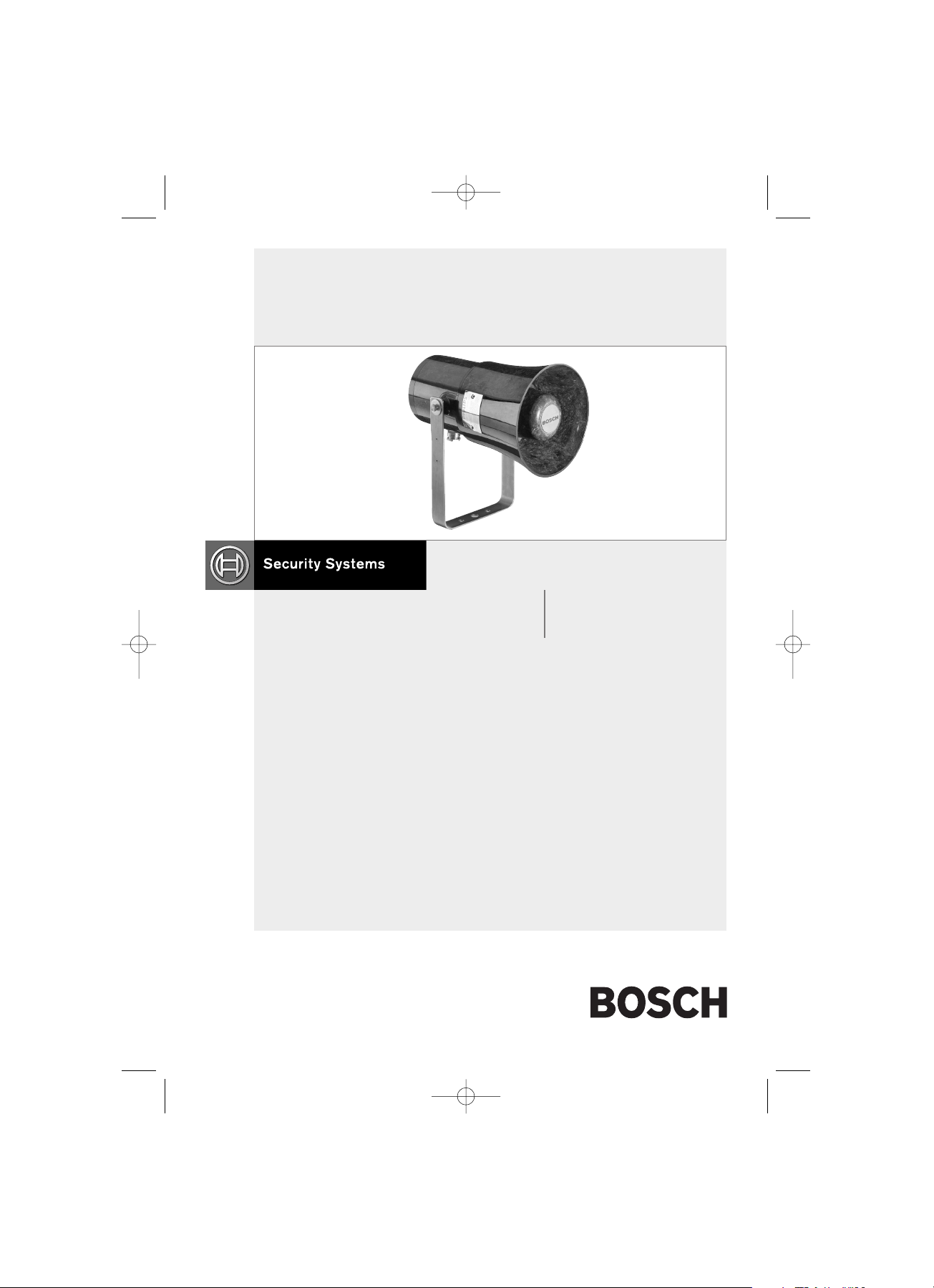
Horn Loudspeaker
Installation Manual
EN LBC 3437/00
LBC 3438/00
LBC3437/LBC3438_instal.manual 05-09-2003 10:18 Page 1
Page 2
1.0 Installation
1.1 General
When installing and operating explosionprotected electrical equipment,
requirements for selection, installation
and operation (e.g. IEC 60079-14) must
be observed.
Cable termination should be in
accordance with specifications applying
to the application.
Bosch recommend that all cables and
cores should be fully identified.
Ensure that only the correct certified
glands are used and that the assembly is
shrouded and correctly earthed. A
sealing washer must be fitted to maintain
the IP rating. Ensure that all nuts, bolts
and fixings are secure.
1.2 Mounting the Unit
The unit mounts via a ‘u’ shaped strap.
This strap is supplied loose and is
attached to the speaker with the 2 off M6
x 20mm screws and washers provided.
The fixing centres of the strap are
indicated on the attached drawing
(see Figure 2). When fixed in position,
the unit’s alignment can be adjusted by
loosening the two M6 screws. The
speaker can then be adjusted to the
required position and the screws
tightened. The speaker should be
positioned such that dust, debris or water
cannot settle in the re-entrant horn.
LBC 3437/00, LBC 3438/00 | Installation Manual
EN
|
2
1.3 To Remove End Cover
Remove the 6 off M5 Cover screws.
1.4 To Fit Gland
To fit the gland supplied refer to the
fitting instructions (see figure 1).
2.0 Operation & Wiring
The speaker is available in 2 standard
wattage ratings (15W and 25W).
Different sound levels can be obtained
by selecting the transformer tappings in
the unit (see figure 3).
3.0 Maintenance
During the working life of the unit, it
should require little or no maintenance.
However, if abnormal or unusual
environmental conditions occur due to
plant damage or accident etc, then visual
inspection is recommended.
If a unit fault should occur, then the unit
should be returned to Bosch for
repair/replacement.
4.0 Certification
Certification to:- EN50014:1997,
EN50018:1994
15W: EExd IICT5
25W: EExd IICT4
ATEX Certification No:
BAS00ATEX2097X
Bosch Security Systems | July 2003
LBC3437/LBC3438_instal.manual 05-09-2003 10:18 Page 2
Page 3

The ATEX certificate and the product
label carry the ATEX group and
category marking: II 2 G D
Where:
signifies compliance with ATEX
II signifies suitability for use in
surface industries
2 signifies suitability for use in
Zone1
G signifies suitability for use in the
presence of gases
LBC 3437/00, LBC 3438/00 | Installation Manual
EN
|
3
5.0 Gland Fitting Instructions
D signifies suitability for use in the
presence of dust
The product label also carries the
following mark:
This signifies unit compliance to the
relevant European directives, in this case
94/9/EC, along with the number of the
notified body issuing the EC type
examination certificate.
• Fit sealing washer to gland.
• Secure gland into the speaker.
• Ensure that item 2 (outer seal) is in its
relaxed state by unscrewing item 4
until there is no compression on the seal.
• Pass the cable through the gland to the
desired length. Then tighten item 4
into item 1 by hand until heavy
resistance is felt then using a spanner
rotate item 4 one turn.
• This completes the termination.
Figure 1
Bosch Security Systems | July 2003
LBC3437/LBC3438_instal.manual 05-09-2003 10:18 Page 3
Page 4

LBC 3437/00, LBC 3438/00 | Installation Manual
EN
|
4
www.boschsecuritysystems.com
9498 974 31013 en Printed in the UK
Updated August 2003
Data subject to change without notice.
6.0 Specifications and Wiring Diagram
1. TYPE LBC3437/00 & LBC3438/00
2. CERTIFICATION No. BAS 00ATEX2097X EExd IIC T4
3. WEIGHT – 5.0 ± 0.3 KG
4. MATERIAL – ENCLOSURE, COVER & HORN – GRP
5. OPTIONAL DUTY LABEL, LETTER SIZE 5 MAX.
6. OPTIONAL TAG LABEL, LETTER SIZE 5 MAX.
7. TERMINALS SUITABLE FOR UP TO 2.5mm2 CABLE
Figure 2 Figure 3
LBC3437/LBC3438_instal.manual 05-09-2003 10:18 Page 4
 Loading...