

Page 1
TCB4 Upgrade Kit for LBB 3500/00, /10 and /30
LBB 3500/00 and LBB 3500/10
LBB 3500/30
Security Systems
Security Systems
Installation Instruction
LBB 3519/20 en
Page 2

Page 3
en
Digital Congress Network | TCB 4 Upgrade Kit LBB 3519/20 | Chapter 1. Upgrade Kit LBB 3519/20
Chapter 1. Upgrade Kit LBB 3519/20
Introduction
The upgrade kit LBB 3519/20 is intended for upgrading of the following DCN Central
Control Units:
• LBB 3500/00 (D)
• LBB 3500/10 (D)
• LBB 3500/30 (D)
The upgrade kit LBB 3519/20 (Trunk Communication Board (TCB 4)) once installed
in the Central Control Units provides the CCUs’ with a high speed serial RS 232
port. This port can be used for either ‘DIRECT’ connection to a DCN control PC,
camera control, test/diagnostic purposes or for remote control.
The TCB4 has two Ports, Port 1 and Port 2. Both Ports can be used if a second hole is
made at the rear of the CCU housing to accommodate the second 9-pole D-type
connector.
If a second port is required, then an additional interconnection cable is
NOTE:
also required. This cable is ordered separately under Code No. 3922 156
24090, through your local Bosch supplier.
REMARKS:
1. Using the ‘DIRECT’ connection method the PC-Network card LBB 3510/00 is
NO longer required.
2. If a ‘DIR ECT’ connection is made between the Control PC and the CCU, the PC
operator has no connection to the PC for headphone or intercom handset. Additional
DCN hardware is required for the operator if these functions are required. Use can be
made of DCN table-top or flush-mounted hardware depending on the requirements.
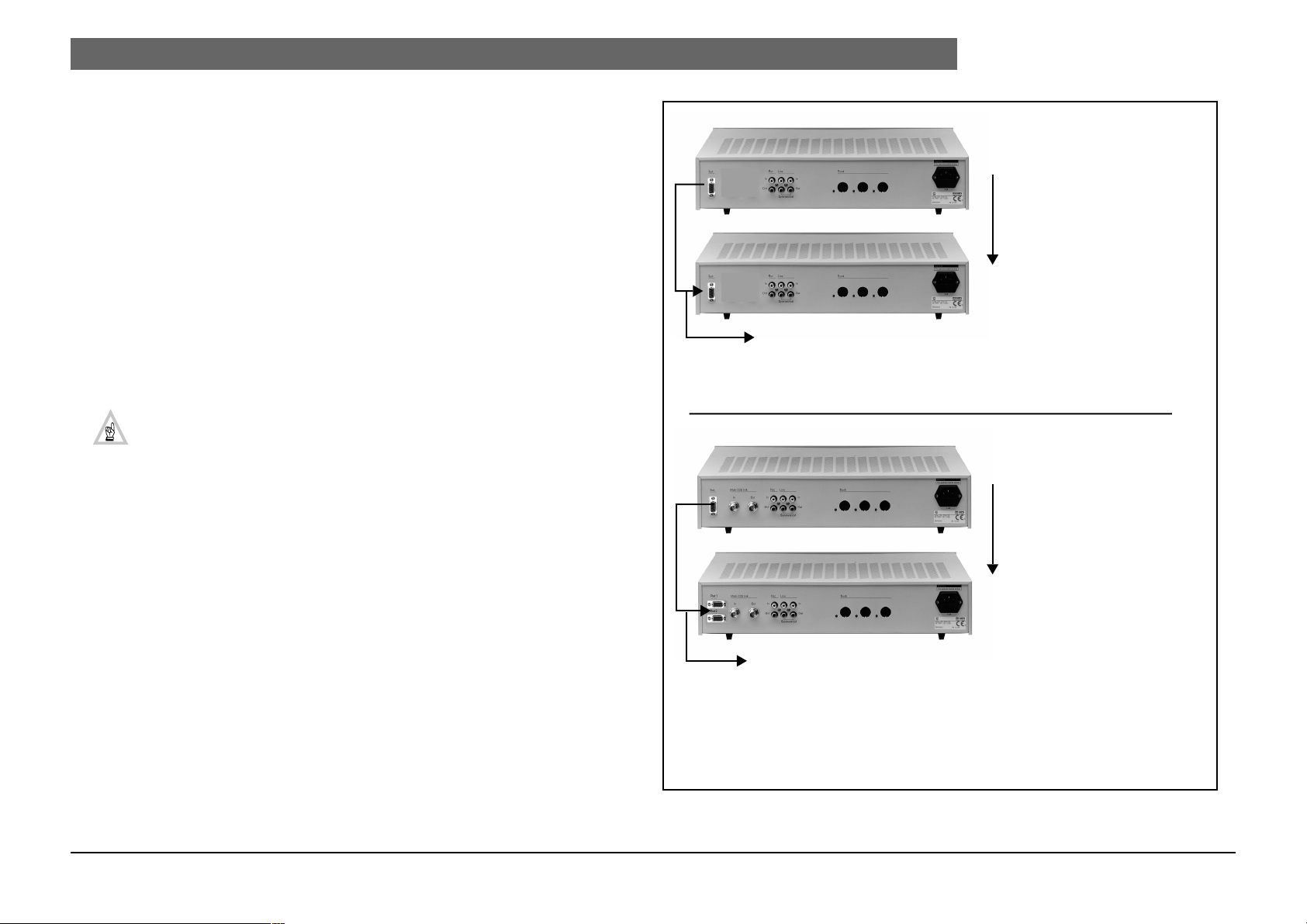
LBB 3500/xx
LBB 3500/xx (with upgrade)
LBB 3500/xx (also applicable for LBB 3500/10)
LBB 3500/xx (with upgrade)
| 3
TCB 2 or 3
TCB 4
Single port only (Port 1)
NOTE: The default settings for Port 1 can be changed to suit
your requirements (see Chapter 3).
TCB 2 or 3
TCB 4
Bosch Security Systems | April 03 | 3922 988 97112 en
Two ports
Port 1 - ‘DIRECT’ connection to DCN control PC (default) (see Note)
Port 2 - Automatic camera control (default) (see Note )
NOTE: The default settings for Port 1 and 2 can be changed to
suit your requirements (see Chapter 3.).
FIGURE 1-1 CCU upgrade kit LBB 3519/20
Page 4

en
1.
Digital Congress Network | TCB 4 Upgrade Kit LBB 3519/20 | Chapter 1. Upgrade Kit LBB 3519/20
1.1 Before you Begin
WARNING:
Before performing any of the procedures described in this
document that require you to remove the top-cover of the CCU,
Installation procedure
2. Locate the TCB (version 2 or 3). For location of the TCB see Fig 1-1.
1. Before removing the top cover of the CCU, disconnect the mains supply and
remove the mains cable from its source and from the rear of the CCU.
2. Disconnect any peripherals connected to the CCU
3. The TCB4 upgrade interface card is shipped in antistatic packaging for protection
3. Remove all interconnection cables from the TCB.
4. Remove the 6 screws securing the TCB,
5. Remove the TCB.
from electrostatic damage.
Once the TCB 2 or 3 is removed proceed as follows:
CAUTION:
touching any unpainted metal surface on the Central Control Unit. This procedure discharges static electricity that might harm the interface card.
Before unwrapping the antistatic packaging, ground yourself by
Minor modifications, (i.e. widening the holes to accommodate the 9-pole D-type
connector(s)) are required at the rear of the CCU. If the upgrade includes two Ports,
then an additional hole is required to accommodate Port 2.
Digital Congress Network
Installation and Operating Manual
REFERENCE:
edition of the DCN Installation and Operating Manual .
(Code No. 3922 988 433xx).
If available refer also to Chapter 4 of the latest
1. Remove the TCB from its packaging (see 1.1 Before you Begin)
2. Position the TCB4 in place and secure using its 6 securing screws.
3. Position and secure the 9-pole D-type connector(s) in their modified hole(s).
4. With reference to FIGURE 1-1 and FIGURE 2-1 connect Port 1 and if applicable Port
1.2 INSTALLING the TCB4 Interface card
2.
5. Connect the TCB4 to both 1/O control boards.
1. Your upgrade kit includes:
- 1 x TCB4 interface card
- Interconnection (ribbon) cable terminated with a 9-pole D-type connector at one end
and a Micromatch connector at the other end.
NOTE:
If two ports are required, then an additional interconnection cable is also
required. This cable is ordered separately under Code no. 3922 156 24090,
through your local Bosch supplier.
6. Double check connections according to FIGURE 1-1 and FIGURE 2-1.
1.3 SET-UP of the TCB4 Interface card
To ensure correct operation of the TCB4, the following settings are required:
1. DIP-switch S14 must be set, to configure the communication protocol and baud
rate used on Port 1 and Port 2 (see Chapter 3 ).
2. DIP-switch S9 must be set to configure the boards functionality (see Chapter 2.1 ).
3. Jumpers X13 and X14 must be set (see Chapter 2.2).
| 4
Remove the top-cover from the CCU.
NOTE: For Multi-CCUs type LBB 3500/30 carefully remove the ‘Multi-CCU’
card from the TCB card. The TCB is located under the ‘Multi-CCU’ card.
Bosch Security Systems | April 03 | 3922 988 97112 en
NOTE:
Once the TCB4 has been successfully installed in the CCU, replace the
top-cover and connect the mains supply to the CCU. Check the CCU for correct operation. If the CCU functions correctly, the CCU should be switched ON
for at least 24 hours to charge the back-up battery located on the TCB4.
Page 5

en
Digital Congress Network | TCB 4 Upgrade Kit LBB 3519/20 | Chapter 1. Upgrade Kit LBB 3519/20
Connection to I/O board
| 5
9-pole D-type connector(s)
Ribbon cabling
Port 1
Port 2
FIGURE 1-2 Internal view of CCU after upgrade
Bosch Security Systems | April 03 | 3922 988 97112 en
6 x securing screws
Trunk Communication Board TCB4
DIP-switch S14
DIP-switch S9
Connection to I/O board
Page 6

en
Digital Congress Network | TCB 4 Upgrade Kit LBB 3519/20 | Chapter 2. Trunk Communication Board (TCB4)
Chapter 2. Trunk Communication Board (TCB4)
Key to symbols
(fig.2-1) :
TCB 4
location Fig. 1-2
X14
1 Jumper X14 (see Table 2.2)
2 S14 DIP-switches 1 - 8 (see Chapter 3) )
3 S10 Push-button switch to reset the Central Control Unit during servicing.
4 Three LEDs (left to right) green/yellow/red. Normally the green/yellow LEDs flash in
sequence, indicating the software is running. Red LED illuminates during system
reset.
5 S9 DIP-switches 1 - 8 (see Chapter 2.1)
6 Yellow LED indicates Digital Signal Processing (DSP) software is running.
7 Connector for multi-trunk board (used only in the multi-CCU)
8 Sockets for inserting flash EPROM (even)
15
Port 2
14
Port 1
13
X41
X40
1
9 Sockets for inserting flash EPROM (odd)
10 SRAM back-up battery 3.6 V (life-time 5 years min.)
11 Jumper X13 (see Table 2.2)
12 Fuse 3.15 amp (delayed)
13 Connector for multi-trunk board (used only in the multi-CCU LBB 3500/30)
14 Serial RS232 Port 1
15 Serial RS232 Port 2
132
87654321
S14
X14
1
81
IC1
X10
21
ON
X17a X17b
IC04
OFF
ON
IC9
IC12
S9
S10
IC11
DIP-switch S14
87654321
S14
See Table 3.1 and 3-2
3
4
ON
12345678
5
6
ON
S10
Reset Switch
DIP-switch S9
ON
12345678
S9
See Table 2.1
| 6
Bosch Security Systems | April 03 | 3922 988 97112 en
12
IC8
X11
X13
123
11
FUSE
BATTERY
X13
10
IC4 IC3
X1
IC6
FIGURE 2-1 Layout ‘Trunk Communication Board (TCB 4)
7
89
Page 7

en
Digital Congress Network | TCB 4 Upgrade Kit LBB 3519/20 | Chapter 2. Trunk Communication Board (TCB4)
S9 DIP-Switch settings
2.4
See fig. 2-1 for location, and Table 2.1 for functionality of the DIP-switches.
Table 2.1 : S9 DIP-switch settings
TCB4
SW 1
SW 2 ON
SW 3
SW 4
SW 5 OFF Reserved (IMPORTANT: must not be changed)
SW 6 ON
ON*
OFF
OFF*
ON
OFF*
OFF Reserved (IMPORTANT: must not be changed)
Chairman priority tone ON (default).
Chairman priority tone OFF
Audio ‘Mix-Minus’ mode activated in combination with SW3 =
OFF
Normal Operation (default).
Audio ‘Insertion’ mode activated in combination with SW2 =
OFF
Normal Operation (default).
Active microphones and request will be permanently switched
off if the priority function of the chairman unit is used.
2.5 Jumper settings
See fig. 2-1 for location, and Table 2-2 for functionality of the jumpers.
Table 2.2 : Jumper settings
TCB4 Default Function
X13
X14 1 & 2 Watchdog active
1 & 2 Jumpered to provide SRAM Battery back-up
| 7
Open when removing back-up battery. (Position 2 & 3)
Open for service purposes. (Position 2 & 3)
OFF*
SW 7
SW 8 ON
* = default setting
DIP switch S9 (default settings)
OFF Reserved (IMPORTANT: must not be changed)
OFF*
S9
12345678
Active microphones will be switched off temporarily if the priority function of the chairman unit is used (default).
Switching on the CCU will activate the BOOT software, this
makes a new download possible. All memory settings will be
erased and returns to the default settings. The unit addresses
will not be erased.
Normal operation (default).
ON
switches 4, 5 and 7 are ‘RESERVED’
Must NOT be changed
For location
see fig.. 2-1.
Bosch Security Systems | April 03 | 3922 988 97112 en
Page 8

en
Digital Congress Network | TCB 4 Upgrade Kit LBB 3519/20 | Chapter 3. CCU Protocol and Serial Port settings
Chapter 3. CCU Protocol and Serial Port settings
For location of DIP-switches see fig. 2-1
3.1 LBB 3500/xx (TCB 4) - Port 1 : DCN Control PC
Port 2 : Camera Control
In a single (stand-alone) CCU systems two serial COM-ports (Port 1 and Port 2) are
available. Both ports can be individually configured. Default settings are;
• 8 data bits
• No parity check
• 1 Stop bit
Table 3.1 : LBB 3500/xx Protocol settings
DIP-switch S14
Simple (Open interface) OFF OFF OFF OFF
Terminal OFF ON OFF ON
Full ON* OFF* ON OFF
Camera control ON ON ON* ON*
* default settings
Port 1 Port 2
Switch Switch Switch Switch
DP-1 DP-2 DP-5 DP-6
NOTE: It is possible to select ‘Full’ protocol on both Port 1 and Port 2. However this is NOT
recommended due to processing power and memory limitations.
| 8
Table 3.2 : LBB 3500/xx Baud rate settings
DIP-switch S14
9.6 K OFF OFF OFF OFF
19.2 K OFF ON OFF* ON*
57.6 K ON OFF ON OFF
115.2 K ON* ON* ON ON
* default settings
DIP-switch S14 (default settings)
87654321
ONS14
Port 1 default
Bosch Security Systems | April 03 | 3922 988 97112 en
Port 1 Port 2
Switch Switch Switch Switch
DP-3 DP-4 DP-7 DP-8
87654321
ONS14
Port 2 default
Page 9

en
Digital Congress Network | TCB 4 Upgrade Kit LBB 3519/20 | Chapter 3. CCU Protocol and Serial Port settings
| 9
Bosch Security Systems | April 03 | 3922 988 97112 en
Page 10

For more information please visit www.boschsecuritysystems.com
© 2003 Bosch Security Systems B.V.
Data subject to change without notice
April 03 | 3922 988 97112 en
 Loading...