

Bosch Integra 500 Installation Manual
Integra 500
INDOOR MODEL
Temperature Modulated with Electronic Ignition
Suitable for heating potable water - Not approved for space heating purposes
(Intended for variable flow applications)
Integra 500 - Natural Gas
Integra 500 - Liquefied Petroleum (LP) Gas
6 720 680 226 (2009/03) US
Warning: If the information in this manual is not
followed exactly, a fire or explosion may result
causing property damage, personal injury or death.
Do not store or use gasoline or other flammable
vapors and liquids in the vicinity of this or any other
appliance.
Improper installation, adjustment, alteration,
service or maintenance can cause injury or
property damage. Refer to this manual. For
assistance or additional information consult a
qualified installer, service agency or the gas
supplier.
In the Commonwealth of Massachusetts this
product must be installed by a licensed plumber or
gas fitter.
Upon completion of the installation, these
instructions should be handed to the user of the
appliance for future reference.
What to do if you smell gas
• Close gas valve. Open windows.
• Do not try to light any appliance.
• Do not touch any electrical switch; do not use any
phone in your building.
• Immediately call your gas supplier from a neighbor’s
phone. Follow the gas supplier’s instructions.
• If you cannot reach your gas supplier, call the fire
department.
• Installation and service must be performed by a
qualified installer, service agency or the gas supplier.

6 720 680 226
2
Index
Index
1 Warning 3
2 Appliance details 4
2.1 Features 4
2.2 Specifications (Technical data) 5
2.3 Unpacking the heater 6
2.4 General rules to follow for safe operation 7
2.5 Dimensions and minimum
installation clearances 8
3 Installation instructions 9
3.1 Specialized tools 9
3.2 Introduction 9
3.3 Venting 9
3.4 Combustion air requirements 20
3.5 Proper location for installing your heater 21
3.6 Heater placement and clearances 21
3.7 Mounting installation 21
3.8 Gas piping & connections 22
3.9 Water connections 25
3.10 Water quality 25
3.11 Domestic hot water recirculation 26
3.12 Filling the condensate trap 27
3.13 Measuring gas pressure 28
4 Electrical connections 29
4.1 Electrical power supply 29
4.2 Position of the fuses in control unit 29
5 Operation instructions 30
5.1 Description LCD Display 30
5.2 For your safety read before operating
your water heater 31
5.3 Power 31
5.4 Temperature selection 31
5.5 Use of optional remote control accessory
(part no. TSTAT2) 32
5.6 Operation 32
5.7 Reset button 32
5.8 Program button 32
5.9 Locked condition 33
6 Maintenance and service 34
6.1 Annual maintenance 34
6.2 Winterizing for seasonal use 34
6.3 Mineral scale build-up 35
6.4 Condensing heat exchanger unit 35
6.5 Adjusting CO2 (carbon dioxide) 36
6.6 Program values 38
6.7 Control board diagnostics 39
7 Troubleshooting 40
7.1 Introduction 40
7.2 Burner does not ignite when
hot water is turned ON 40
7.3 Water is too hot 40
7.4 Water is not hot enough 40
7.5 Low water flow/pressure 41
7.6 Hot water temperature fluctuates at tap 41
7.7 Noisy burner/heater during operation 41
8 Problem solving 43
8.1 Error code diagnostics 43
9 Electrical diagram 47
10 Sensor resistance charts 48
11 Integra 500 Functional scheme 50
12 Interior components diagram
and parts list 51
12.1 Interior components 51
12.2 Components diagram 53
13 Protecting the environment 60
14 Limited Warranty 61
6 720 680 226
Warning
3
1 Warning
For your safety
Do not store or use gasoline or other flammable,
combustible or corrosive vapors and liquids in the
vicinity of this or any other appliance.
Warning: Carefully plan where you
install the heater. Correct combustion
air supply and flue pipe installation are
very important. If a gas appliance is not
installed correctly, fatal accidents can
result such as, carbon monoxide
poisoning or fire.
Warning: Exhaust gas must be vented
to outside using approved vent material
See table 2, page 10 (For Canada use
only ULCS636 approved material).
Vent and combustion air connector
piping must be sealed gas-tight to
prevent possibility of flue gas spillage,
carbon monoxide emissions and risk of
fire, resulting in severe personal injury
or death. Approved vent terminators
must be used when penetrating to the
outside.
Warning: Place the heater in a location
where water leaks will do NO DAMAGE
to adjacent areas or lower floors.
Warning: Field wiring connections and
electrical grounding must comply with
local codes, or in the absence of local
codes, with the latest edition of the
National Electric Code, ANSI/NFPA 70,
or in Canada, all electrical wiring must
comply with the local codes and the
Canadian Electrical Code, CSA C22.1
Part 1.
Warning: Shock hazard: line voltage is
present. Before servicing the water
heater, unplug power supply cord from
outlet. Failure to do so could result in
severe personal injury or death.
Warning: The heater must be
disconnected from the gas supply
piping system during any pressure
testing of that system at test pressures
equal to or more than 0.5 psig.
Warning: The appliance should be
located in an area where leakage of the
heater or connections will not result in
damage to the area adjacent to the
appliance or to lower floors of the
structure. When such locations cannot
be avoided, it is recommended that a
suitable drain pan, adequately drained,
be installed under the appliance. The
pan must not restrict combustion air
flow.
Warning: The maximum inlet gas
pressure must not exceed the value
specified by the manufacturer and that
the minimum value listed is for the
purposes of input adjustment.
Warning: If a water heater is installed in
a closed water supply system, such as
one having a backflow preventer in the
cold water supply line, means shall be
provided to control thermal expansion.
Contact the water supplier or local
plumbing inspector on how to control
this situation.
Warning: Keeping appliance area clear
and free from combustible materials,
gasoline and other flammable vapors
and liquids.
Warning: Do not obstruct the flow of
combustion and ventilation air.
Warning: Precautions must be taken
prior to manually operating the relief
valve to avoid contact with hot water
coming out of the relief valve and to
prevent water damage.
Caution: Label all wires prior to
disconnection when servicing controls.
Wiring errors can use improper and
dangerous operation.
Verify proper operation after servicing.
6 720 680 226
4
Appliance details
FCC:
This device complies with Part 15 of the FCC rules.
Operation is subject to the following two conditions: (1)
This device may not cause harmful interference, and (2)
this device must accept any interference received,
including interference that may cause undesired operation.
Fig. 1
2 Appliance details
2.1 Features
Parts
• Key Pad interface control
• High power pre-mix compact burner with low NOx
emissions
• Modulating Gas Valve with constant gas:air ratio
control
• Modulating water valve for improved comfort and
temperature control.
High quality materials for long working life
• Copper heat exchanger
• High efficiency Ceramat Burner
• Compact space saver: mounts on a wall with a
supplied bracket.
Features
• Easily removable one-piece cover
• LCD Display with backlight
• On/Off and Temperature control switches
• Reset button
• Program button (Selectable temperature default)
• Failure codes for easy diagnostics and repair
• Real-time diagnostics for troubleshooting/informa-
tional purposes.
Accessories (Bosch part #)
• Optional wireless remote control to operate with the
appliance (TSTAT2)
• Cascading kit (TLINK)
• Outdoor kit (BSHTOK)
• External water filter (part # 8 703 305 356)
• Concentric termination kit (196016)
• Freeze prevention kit (7709003665)
1)
• Exhaust/Intake bird screen (L2594)
• Condensate drain tee (196061) [included with Con-
centric termination kit].
Warning: If a relief valve discharges periodically, this may be due to thermal expansion in a closed water supply
system. Contact the water supplier or
local plumbing inspector on how to correct this situation. Do not plug the relief
valve.
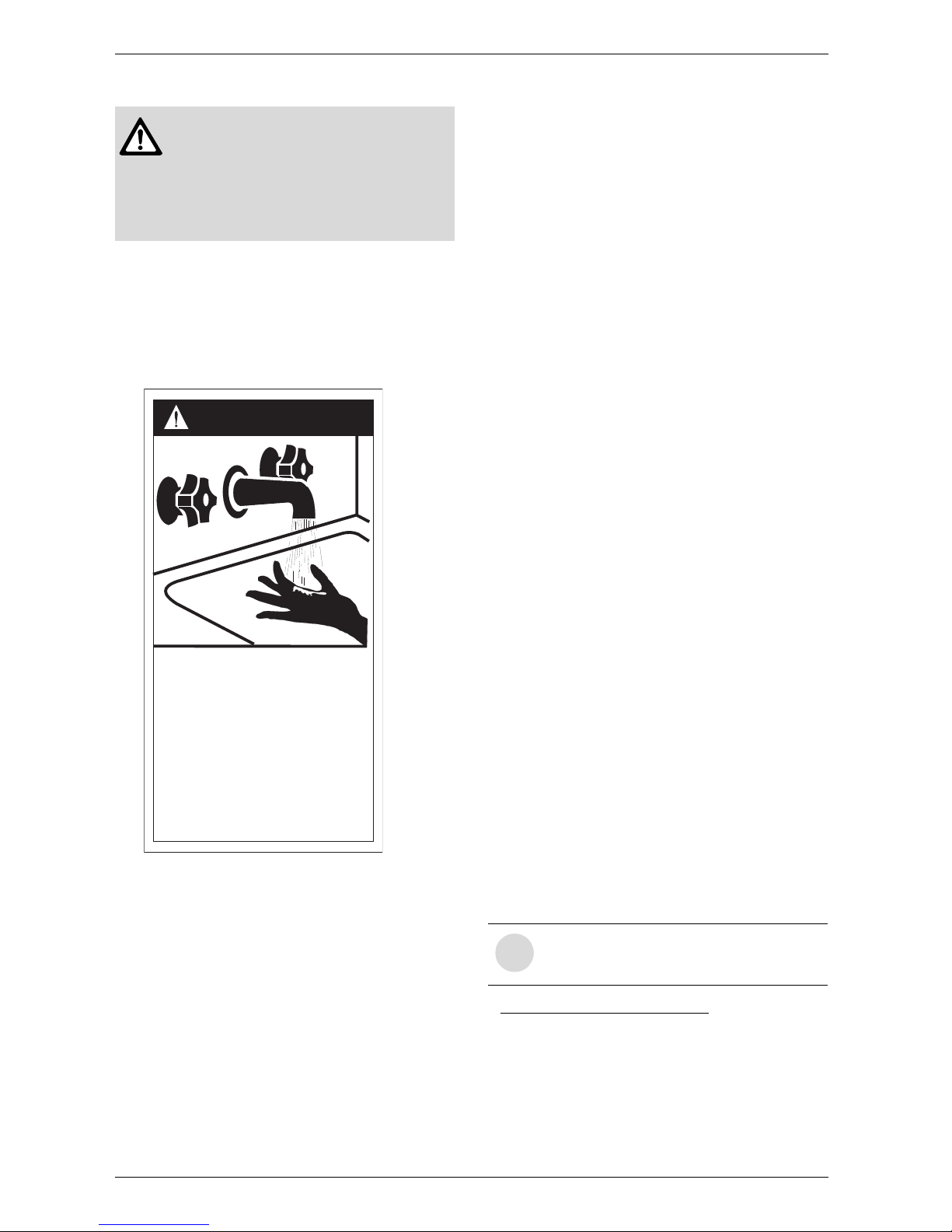
HOT
BURN
D A N G E R
Watertemperatureover125°Fcan
causesevereburnsinstantlyor
deathfromscalds.
Children,disabledandelderlyare
athighestriskofbeingscalded.
Seeinstructionmanualbefore
settingtemperatureatwater
heater.
Feelwaterbeforebathingor
showering.
6720608643-16.1AL
1) The freeze prevention kit is designed to provide
protection for the water heater down to approximately
5°F for short term conditions only. It will not protect the
appliance in areas where the temperature is routinely
expected to be below freezing.
- The freeze prevention kit will not protect plumbing
outside the appliance from freezing. Precautions should
be taken.
i
BOSCH is constantly improving its
products, therefore specifications are
subject to change without prior notice.

6 720 680 226
Appliance details
5
2.2 Specifications (Technical data)
Approved in US/Canada
Capacity
Maximum flow rate: 8.0 GPM (30 l/min) at a 45°F
(25°C) rise.
Maximum output
179,300 Btu/h (52.5 kW)
Maximum input
195,000 Btu/h (57.1 kW)
Efficiency in %
Thermal efficiency > 92%
Minimum Input
19,900 Btu/h (5.8 kW)
Temperature Control
Selection range: 100°F (38°C) - 140°F (60°C)
Default temperature: 122°F (50°C)
Stability: +/- 2°F (+/- 1°C)
Gas Requirement
Gas connection (inches) - ¾”
Inlet gas pressure under operation (with a high hot
water flow rate)*
• Propane: 8” - 13” water column
• Natural Gas: 3.5” - 10.5” water column.
* To measure Gas Pressure, see Measuring Gas
Pressure, chapter 3.13, page 28.
Water
• Hot water connection (inches) - ¾”
• Cold water connection (inches) - ¾”
• Water valve material: Polymer (PPS) (Polypropylene
Sulfid)
• Minimum water flow: 0.65 gallon/minute (2.5 l/m)
Note: Activation varies with inlet water temperatures
from 0.65 - 1.6 gallon/minute (2.5 - 6.1 l/m).
• Minimum recommended water pressure: 30 PSI
(2.07 bar)
• Minimum well pressure 40 psi, see page 25.
• Connections:
– Bottom of heater
Combustion
• NOx ≤ 14 Ng/J
(Nanograms of NOx (calculated as NO2) per
Joule of heat output).
• CO ≤ 290 ppm (measured)
• CO
2
level set from factory, see chapter 6.5, page 36.
Dimensions
• Depth (in): 11¼” (286 mm)
• Width (in): 17
7
/
8
” (452 mm)
• Height (in): 30½” (775 mm)
• Weight: 74 pounds (33.5 kg).
Gas types
Natural Gas.
LP Gas.
Voltage
120 V AC (60 Hz) nominal
Amperage
Idle - 40 mA
Operation - ≤ 2.5 A
Noise
45 - 65 db (A)
Safety devices
• Flame failure device (ionization flame rod sensor)
• Pressure relief valve (supplied with heater)
• Over heat prevention (temperature limiter)
• Inlet temperature sensor
• Outlet temperature sensor
• Back flow temperature sensor
• Exhaust gas temperature sensor.
Water protection
IP X4 (protection against water drops)
i
If appliance is installed at elevations above
2000ft, refer to Section 3.3.6 Fan speed
adjustment.
6 720 680 226
6
Appliance details
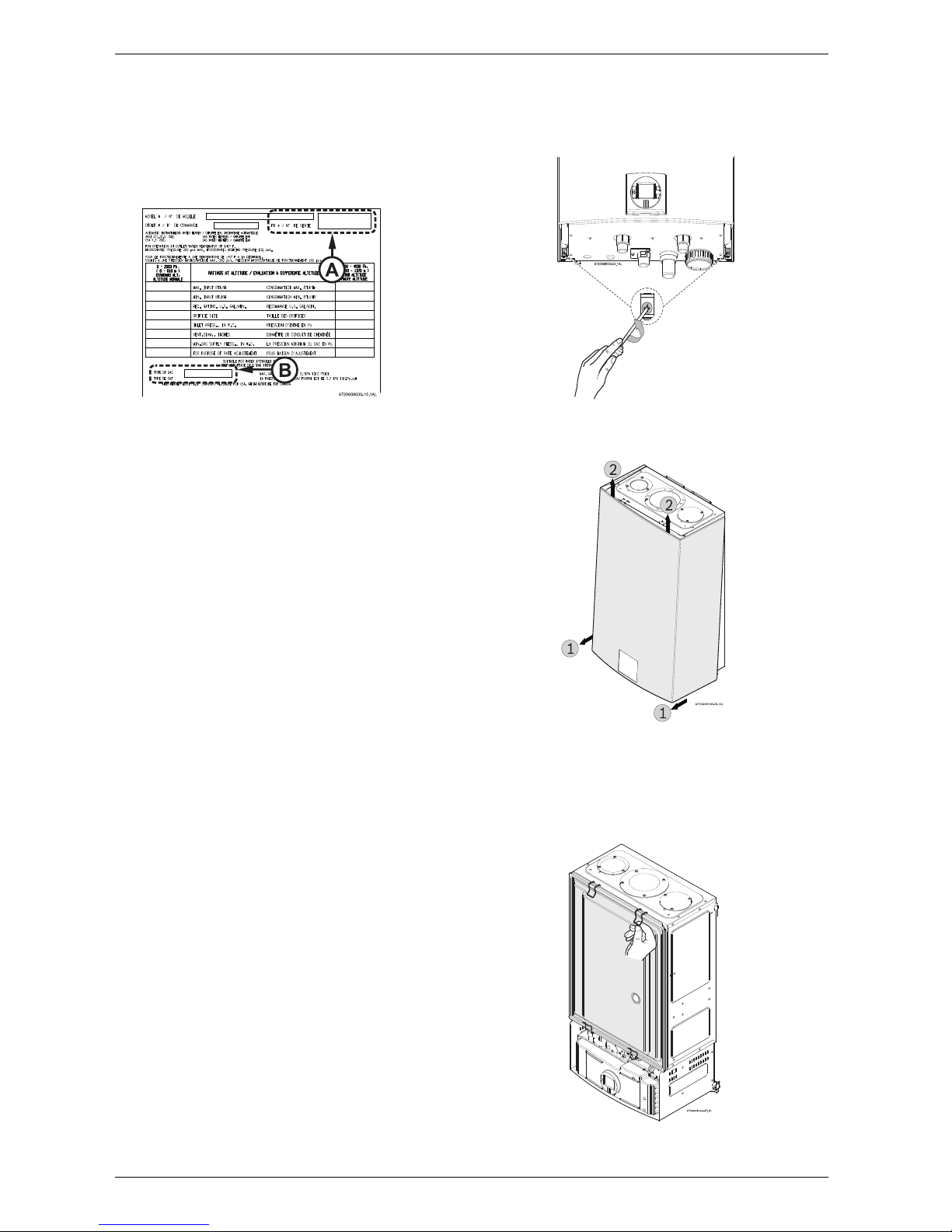
2.3 Unpacking the heater
Before installing the unit, be certain you have the
correct heater for your type of Gas - Propane or
Natural Gas. Identification labels are found on the
shipping box, and on the rating plate which is located on
the right side panel of the cover.
Fig. 2 Rating plate
A Serial number
B Type of gas
The box includes:
• Integra 500
• Pressure relief valve (150 psi / 200,000 Btu rating)
• Bracket for wall hanging the heater
• Exhaust vent adaptor (with 4 screws and gasket
provided)
• Combustion air inlet adaptor (with 3 screws and gasket provided)
• Installation manual (manual can be downloaded at
www.boschpro.com)
• Product registration card
• Energy Guide label.
Please complete and return the enclosed product
registration card.
The water heater is not approved or designed for:
• Manufactured (mobile) homes, boats or any
mobile installation. (Modular homes are
acceptable for installation).
• Use above 8000 ft A.S.L. altitude (see page 18).
• Outdoor installation without installation of
Outdoor kit (PTOK).
• Applications where inlet water temperature is
higher than 140°F (60°C). A 3-way valve or
mixing valve must be installed before the
appliance if inlet water temperature exceeds
this limit.
• Space heating purposes.
To remove front cover
B Loosen the two Philips head screws located on
bottom rear of cover (see Fig. 3).
Fig. 3 Loosen the two screws
B Lift front cover panel upward and remove.
Fig. 4 Remove the front cover
To remove combustion cover (service only)
B Open the four clips and remove the combustion
cover (see Fig. 5).
Fig. 5 Remove the combustion cover

6 720 680 226
Appliance details
7
2.4 General rules to follow for safe
operation
B 1. You must follow these instructions when you
install your heater. In the United States: The
installation must conform with local codes or, in the
absence of local codes, the National Fuel Gas Code
ANSI Z223.1/NFPA 54.
In Canada: The Installation must conform with CSA
B149.(1,2) INSTALLATION CODES and /or local
installation codes.
B 2. Carefully plan where you install the heater. Correct
combustion air supply and vent pipe installation are
very important. If not installed correctly, fatal
accidents can occur, such as carbon monoxide
poisoning or fire.
B 3. When the unit is installed indoors and ROOM
SEALED (twin pipe) it is permitted to be located in
bathrooms, bedrooms and occupied rooms that are
normally kept closed. See chapter 3.3 (page 9). If the
unit will be installed indoors and use indoor
combustion air, the place where you install the heater
must have enough ventilation. The National Fuel
Gas Codes do not allow UNSEALED gas fired
water heater installations in bathrooms,
bedrooms or any occupied rooms normally
kept closed. See chapter 3.4 (page 20).
B 4. You must correctly vent your heater. See
chapter 3.3 (page 9) on VENTING.
B 5. The appliance and its gas connection must be leak
tested before placing the appliance in operation.
The appliance must be isolated from the gas supply
piping system by closing its individual manual gas
shutoff valve (not supplied with heater) during any
pressure testing at pressures in excess of ½ Psig
(3.5 kPa).
B 6. Keep water heater area clear and free from
combustibles and flammable liquids. Do not locate
the heater over any material which might burn.
B 7. Correct gas pressure is critical for the proper
operation of this heater. Gas piping must be sized to
provide the required pressure at the maximum output
of the heater, while all the other gas appliances are in
operation. Check with your local gas supplier, and
see the section on connecting the gas supply. See
chapter 3.8 (page 22).
B 8. Should overheating occur or the gas supply fail to
shut off, turn off the gas supply at the manual gas
shut off valve, on the gas line. Note: manual gas
shutoff valve is not supplied with the heater but must
be field installed.
B 9. Do not use this appliance if any part has been
underwater. Immediately call a qualified service
technician to inspect the appliance and to replace
any part of the control system and any gas control
which has been underwater.
B 10. Failure to install heater correctly may lead to
unsafe operation and void the warranty.
6 720 680 226
8
Appliance details
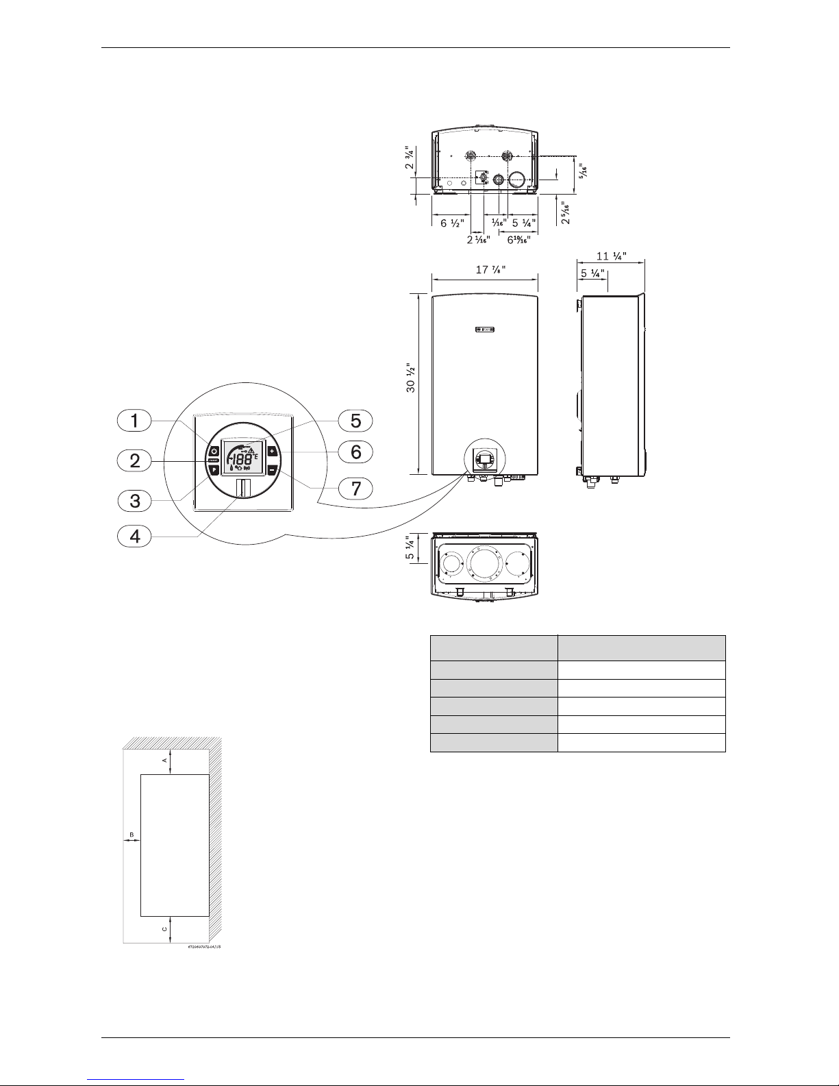
2.5 Dimensions and minimum installation clearances
Fig. 6 Dimensions
1 On/Off button
2 Reset button
3 Program key
4 Power ON or stand-by LED
5 LCD display
6 Up button
7 Down button
Fig. 7 Minimum clearances
Note: For servicing access, a 2ft clearance is
recommended to the front cover.
6720608000-03.2AL
6
4
Model Integra 500
TOP (A) 12”
FRONT (B) 1”
BACK 0”
SIDES 1”
FLOOR (C) 12”
Table 1 Minimum clearances
6 720 680 226
Installation instructions
9
3 Installation instructions
3.1 Specialized tools
The following specialized tools may be required for
installation:
• Manometer
• Multi-meter
• Combustion Gas Analyzer.
3.2 Introduction
Please follow these instructions. Failure to follow
instructions may result in:
B Damage or injury.
B Improper operation.
B Loss of warranty.
3.3 Venting
Warning: The water heater must be
installed by a qualified installer in
accordance with these instructions. If
improperly installed, a hazardous condition
such as explosion or carbon monoxide
poisoning could result. Bosch
Thermotechnology Corp. is not
responsible for improperly installed
appliances.
i
Common installation practice is to
first determine the venting/
combustion air point of termination,
then design the piping layout back to
the heater.
Warning:
B Do not reduce the exhaust or
combustion air vent pipe sizes.
B Do not common vent with any other
vented appliance or stove.
B Do not use Type-B vent as the actual
exhuast vent system for the appliance.
Warning: Failure to vent the exhaust
gases to the outside (see Table 2 for
proper material) may result in
dangerous flue gases filling the
structure in which it is installed.
Warning: In areas where outside
temperatures routinely come close to
freezing, sealed combustion operation
is required. Concentric termination or
separate terminations for combustion
and vent, must be installed on the same
wall or roof surface; however, never
facing the direction of prevailing winds.
Failure to do so may result in heat
exchanger freezing and bursting. This
failure is not covered under the
manufacturer's warranty.
Warning: Protect the exhaust and inlet
from leaves and debris by installing a
screen on the end of the terminator.
¼" mesh minimum opening
recommended on screen.
6 720 680 226
10
Installation instructions
3.3.1 Vent material
All combustion air and vent pipe materials and fittings
must comply with the following:
For specific questions concerning vent material,
specifications, usage or installation, please
contact the vent manufacturer directly.
All vent connections must be glued, except for the
exhaust accessory (see section 3.3.4) which is
screwed into place on the top of the appliance. Slide
the vent pipe into the exhaust accessory. The exhaust
pipe must be properly supported and must be pitched
a minimum of a ¼ inch per foot back to the appliance.
This allows the condensate to drain properly.
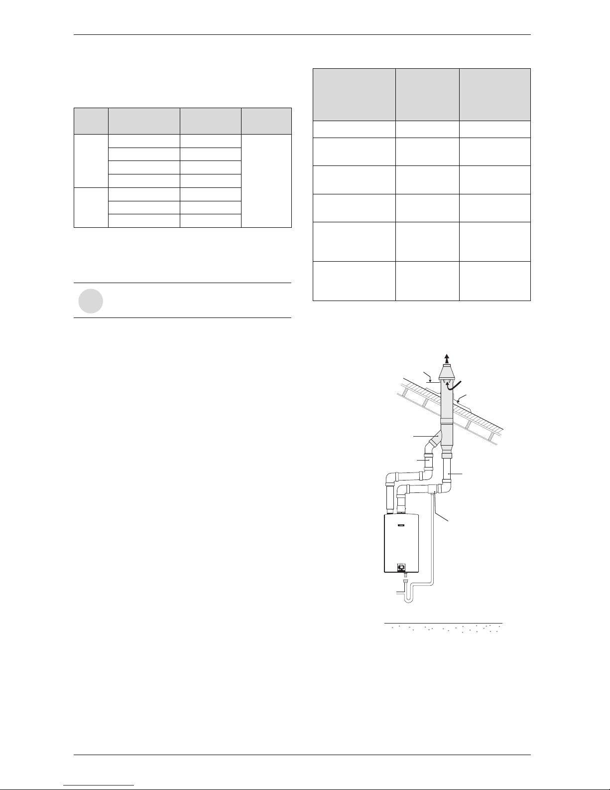
An optional concentric vent/air intake termination can
be used for the installation of a vertical or horizontal
venting system. (see Fig. 8).
The concentric vent/air intake body can be ordered
from your local wholesaler. (Part# 196016).
The appliance can also be installed with separate air
intake and exhaust piping (see Fig. 11, Fig. 17 and Fig.
18, page 16).
Fig. 8 Concentric vent kit example
Item Material United States Canada
Vent or
air pipe
and
fitting
PVC schedule 40 ANSI/ASTM D1785
CSA or ULC
certified only
(ULC-S636)
PVC-DWV ANSI/ASTM D2665
CPVC schedule 40 ANSI/ASTM F441
ABS-DWV schedule 40 ANSI/ASTM D2661
Pipe
cement /
primer
PVC ANSI/ASTM D2564
CPVC ANSI/ASTM F493
ABS ANSI/ASTM D2235
Table 2 Approved vent material
i
Do not use cellular foam core pipe.
Description Length
Kit part no.
and quantity
196016
3- In. Rain Cap N/A 1
4- In. Diameter
SDR-26 Pipe
24 In. long 1
3- In. Y
Concentric Fitting
N/A 1
2- ½ In. Diameter
SDR-26 Pipe
37-1/8 in. long 1
3- In. Termination
Tee (part #
196061)
N/A 1
3x3x1.5- In Condensate drain bushing (part# 196278)
N/A 1
Table 3 Concentric vent part breakdown
6720608836-27.1Av
3 (76mm)"
3 (76mm)"
INTAKE
EXHAUST
COMBUSTION
AIR
MAINTAIN 12 IN. (18 IN. FOR CANADA)
MINIMUM CLEARANCE ABOVE
HIGHEST ANTICIPATED SNOW LEVEL.
MAXIMUM OF 24 IN. ABOVE ROOF.
EXHAUST
ROOF BOOT/
FLASHING (FIELD
SUPPLIED
DRAIN TEE
(196278)
CONCENTRIC
VENT KIT
(196016)
6 720 680 226
Installation instructions
11
3.3.2 Vent specifications
Establish vent clearances that comply with the vent
manufacturer's specifications and all applicable
national/local codes.
Venting specifications
Condensate drain requirements
An external condensate drain (not supplied with the
heater) must be installed under the following
conditions:
• All vertical terminating vent installations.
• Horizontal terminating vent installations where the
total linear vent length is greater than 6 feet (1.8 m).
• Vent installations where any section of the exhaust
vent pipe passes through an unconditioned space.
Minimum combustion air and exhaust pipe
length
The minimum exhaust pipe length is 3 feet (1m) of
straight vent pipe. The minimum combustion air pipe
length is one 90° elbow.
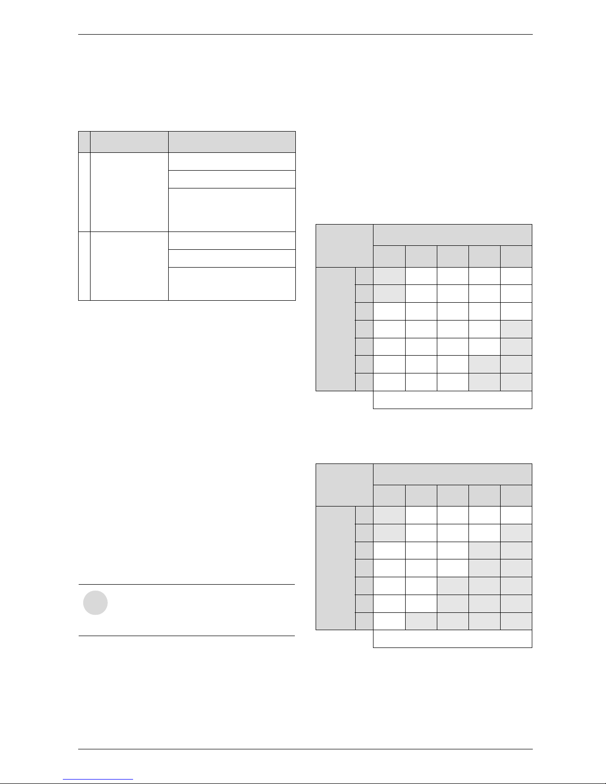
Maximum combustion air and exhaust pipe
length
The following tables (Tables 5 & 6) display the
maximum allowable straight pipe lengths for
combustion air and exhaust piping with consideration to
the number of elbows used.
Step 1: If using the twin pipe penetration system, refer
to table 5. If using the concentric vent kit
system, refer to table 6.
Step 2: Total the number of 90° elbows and 45°
elbows used on the exhaust piping.
Step 3: Use this value in the appropriate table to
determine the maximum straight exhaust pipe
length allowed.
Step 4: Total the number of 90° elbows and 45°
elbows used on the combustion air piping.
Step 5: Use this value in the appropriate table to
determine the maximum straight combustion
air pipe length allowed.
* Not allowed. At least one 90º elbow required.
** Not allowed. Minimum of 3 feet (1m) of straight pipe required.
* Not allowed. At least one 90º elbow required.
** Not allowed. Minimum of 3 feet (1m) of straight pipe required.
Note: Include pipe length that is part of the concentric terminal.
Diam. Aproved terminals
E
x
h
a
u
s
t
3 or 4 inches
“T” terminal
90° elbow
Concentric
(196016)
I
n
t
a
k
e
3 or 4 inches
“T” terminal
90° elbow
Concentric
(196016)
Table 4 Venting specifications for intake and exhaust
i
Note: 90° elbows used for
terminations should not be counted
in the exhaust and combustion air
piping.
Twin Pipe
System
# of 90° elbows
0 1 2 3 4
# of 45°
elbows
0 N/A* 26 21 16 11
1 N/A* 23 18 13 8
2 23 20 15 10 5
3 20 17 12 7 N/A**
4 17 14 9 4 N/A**
5 14 11 6 N/A** N/A**
6 11 8 3 N/A** N/A**
Maximum allowable straight pipe length (ft)
Table 5 Maximum allowable straight pipe length (twin
pipe)
Concentric
pipe System
# of 90° elbows
0 1 2 3 4
# of 45°
elbows
0 N/A* 18 13 8 3
1 N/A* 15 10 5 N/A**
2 15 12 7 N/A** N/A**
3 12 9 4 N/A** N/A**
4 9 6 N/A** N/A** N/A**
5 6 3 N/A** N/A** N/A**
6 3 N/A** N/A** N/A** N/A**
Maximum allowable straight pipe length (ft)
Table 6 Maximum straight pipe length (concentric ter-
minal)
6 720 680 226
12
Installation instructions
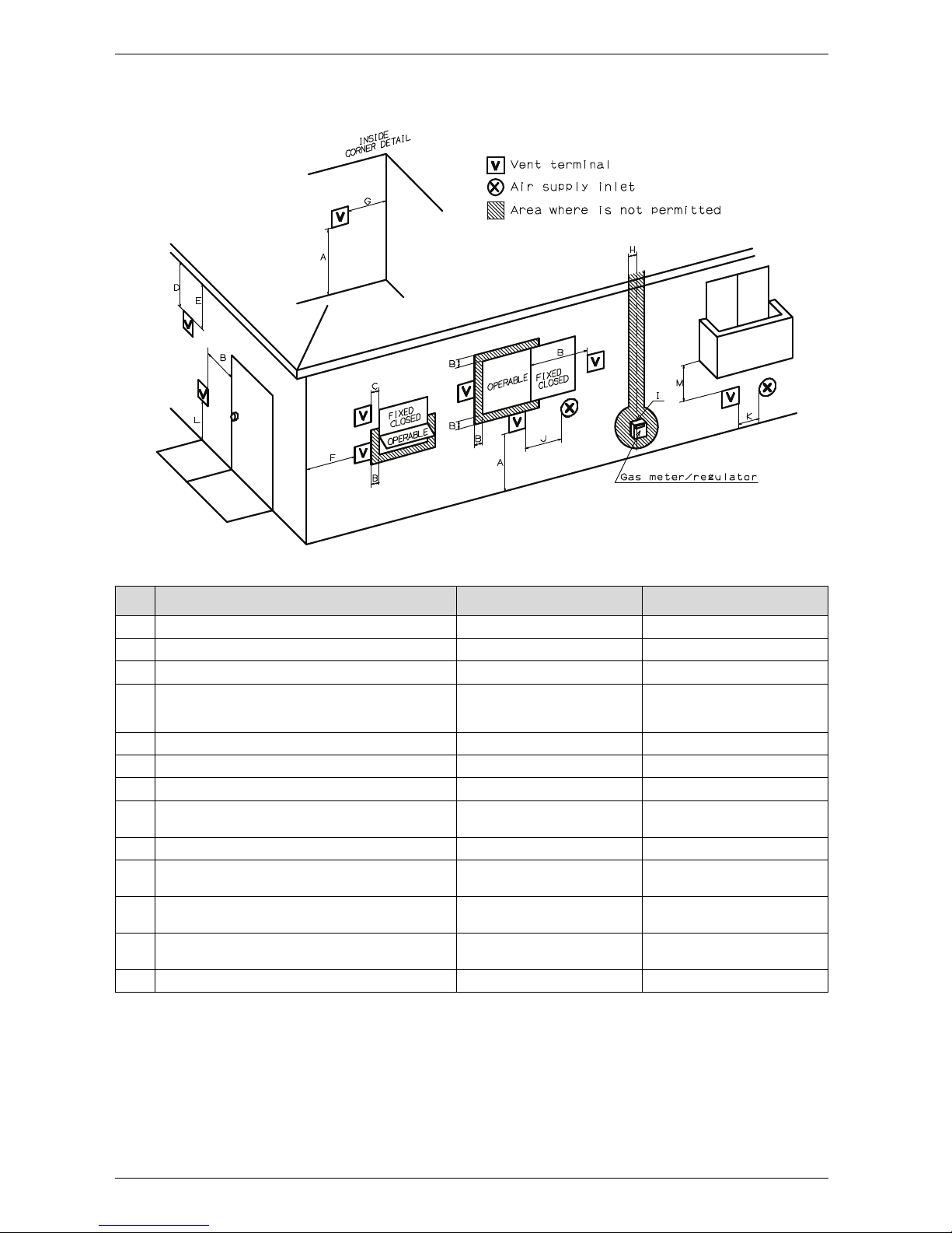
Required direct vent terminal clearances (twin pipe / concentric penetration)
Fig. 9
* For clearances not specified in ANSI Z223.1 / NFPA 54 or CSA-B149.1, one of the following shall be indicated:
a) A minimum clearance value determined by testing in accordance with section 2.20, or;
b) A reference to the following footnote:
“Clearance in accordance with local installation codes and the requirements of the gas supplier.”
6720608836-23.1Av
Canadian installations
1)
U.S. installations
2)
A Clearance above grade, veranda, porch, deck or balcony 12 in. 12 in.
B Clearance to window or door that may be opened 36 in. 12 in.
C Clearance to permanently closed window * *
D Vertical clearance to ventilated soffit located above the vent
terminator within a horizontal distance of 2 feet (61cm) from the
center line of the terminator
* *
E Clearance to unventilated soffit * *
F Clearance to outside corner * *
G Clearance to inside corner * *
H Clearance to each side of center line extended above meter/
regulator assembly
36 in. within a height 15 feet above
meter/ regulator assembly
*
I Clearance to service regulator vent outlet 36 in. *
J Clearance to non-mechanical air supply inlet to building or the
combustion air inlet to any other application
36 in. 12 in.
K Clearance to mechanical air supply inlet 72 in. 36 in. above if within 10 feet
horizontally
L Clearance above paved sidewalk or paved driveway located on
public property
84 in.
3)
*
M Clearance under veranda, porch deck or balcony 12 in.
4)
*
Table 7
1) In accordance with the current CSA B149.1 Natural Gas and Propane Installation Code
2) In accordance with the current ANSI Z223.1 / NFPA 54 National Fuel Gas Code
3) A vent shall not terminate directly above a sidewalk or paved driveway that is located between two single family dwellings and serves both dwellings.
4) Permitted only if veranda, porch, deck or balcony is fully open on a minimum of two sides beneath the floor.
6 720 680 226
Installation instructions
13
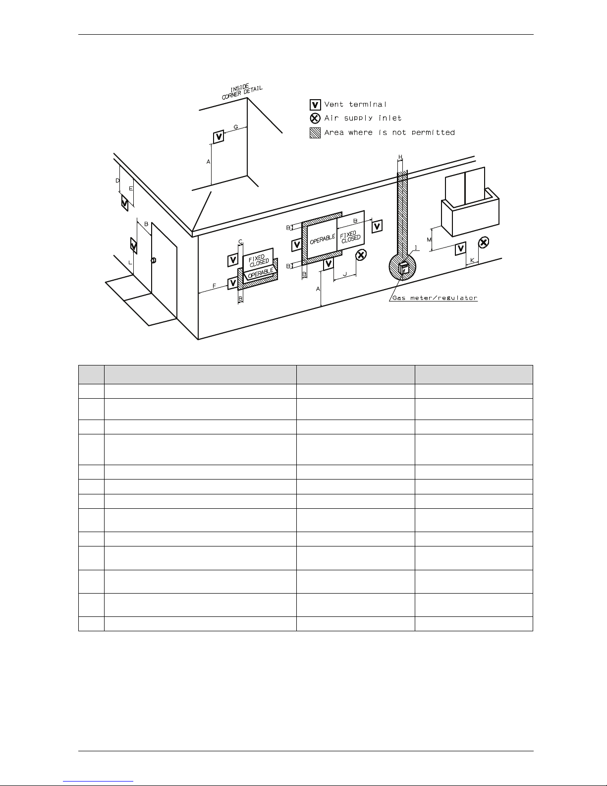
Required other than direct vent terminal clearances (single pipe penetration)
Fig. 10
* For clearances not specified in ANSI Z223.1 / NFPA 54 or CSA-B149.1, one of the following shall be indicated:
a) A minimum clearance value determined by testing in accordance with section 2.20, or;
b) A reference to the following footnote:
“Clearance in accordance with local installation codes and the requirements of the gas supplier.”
6720608836-23.1Av
Canadian installations
1)
U.S. installations
2)
A Clearance above grade, veranda, porch, deck or balcony 12 in. 12 in.
B Clearance to window or door that may be opened 36 in. 4 feet below or to side of opening;
1 foot above opening
C Clearance to permanently closed window * *
D Vertical clearance to ventilated soffit located above the vent
terminator within a horizontal distance of 2 feet (61cm) from the
center line of the terminator
* *
E Clearance to unventilated soffit * *
F Clearance to outside corner * *
G Clearance to inside corner * *
H Clearance to each side of center line extended above meter/
regulator assembly
36 in. within a height 15 feet above
meter/ regulator assembly
*
I Clearance to service regulator vent outlet 36 in. *
J Clearance to non-mechanical air supply inlet to building or the
combustion air inlet to any other application
36 in. 4 feet below or to side of opening;
1 foot above opening
K Clearance to mechanical air supply inlet 72 in. 36 in. above if within 10 feet
horizontally
L Clearance above paved sidewalk or paved driveway located on
public property
84 in.
3)
84 in.
M Clearance under veranda, porch deck or balcony 12 in.
4)
*
Table 8
1) In accordance with the current CSA B149.1 Natural Gas and Propane Installation Code
2) In accordance with the current ANSI Z223.1 / NFPA 54 National Fuel Gas Code
3) A vent shall not terminate directly above a sidewalk or paved driveway that is located between two single family dwellings and serves both dwellings.
4) Permitted only if veranda, porch, deck or balcony is fully open on a minimum of two sides beneath the floor.
6 720 680 226
14
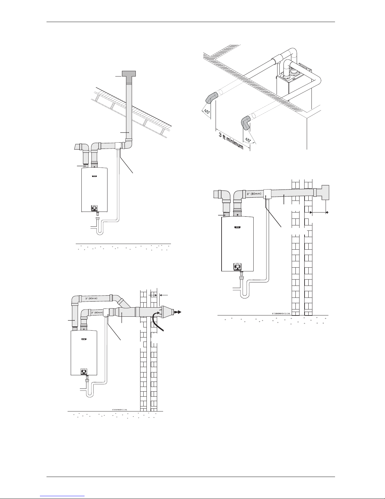
Installation instructions
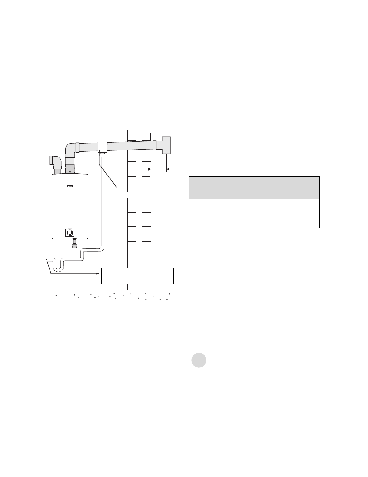
3.3.3 Vent configuration examples
Below are approved examples of vertical and horizontal
venting installations.
Fig. 11 Vertical venting system (single pipe penetra-
tion*)
* Warning: For non-freezing climates only!
Fig. 12 Horizontal venting system (concentric vent)
Fig. 13 Horizontal parallel venting system (twin pipe
direct vent)
Fig. 14 Horizontal venting system (single pipe pene-
tration*)
*Warning: For non-freezing climates only!
6720608836-24.1Av
3" (80mm)
INTAKE
EXHAUST
MAINTAIN 12 IN. (18 IN. FOR CANADA)
MINIMUM CLEARANCE ABOVE
HIGHEST ANTICIPATED SNOW LEVEL.
MAXIMUM OF 24 IN. ABOVE ROOF.
DRAIN TEE
INTAKE
EXHAUST
MINIMUM
1”
EXHAUST
COMBUSTION
AIR
DRAIN TEE
6720608836-25.1Av
INTAKE
EXHAUST
4” Min.
DRAIN TEE
6 720 680 226
Installation instructions
15
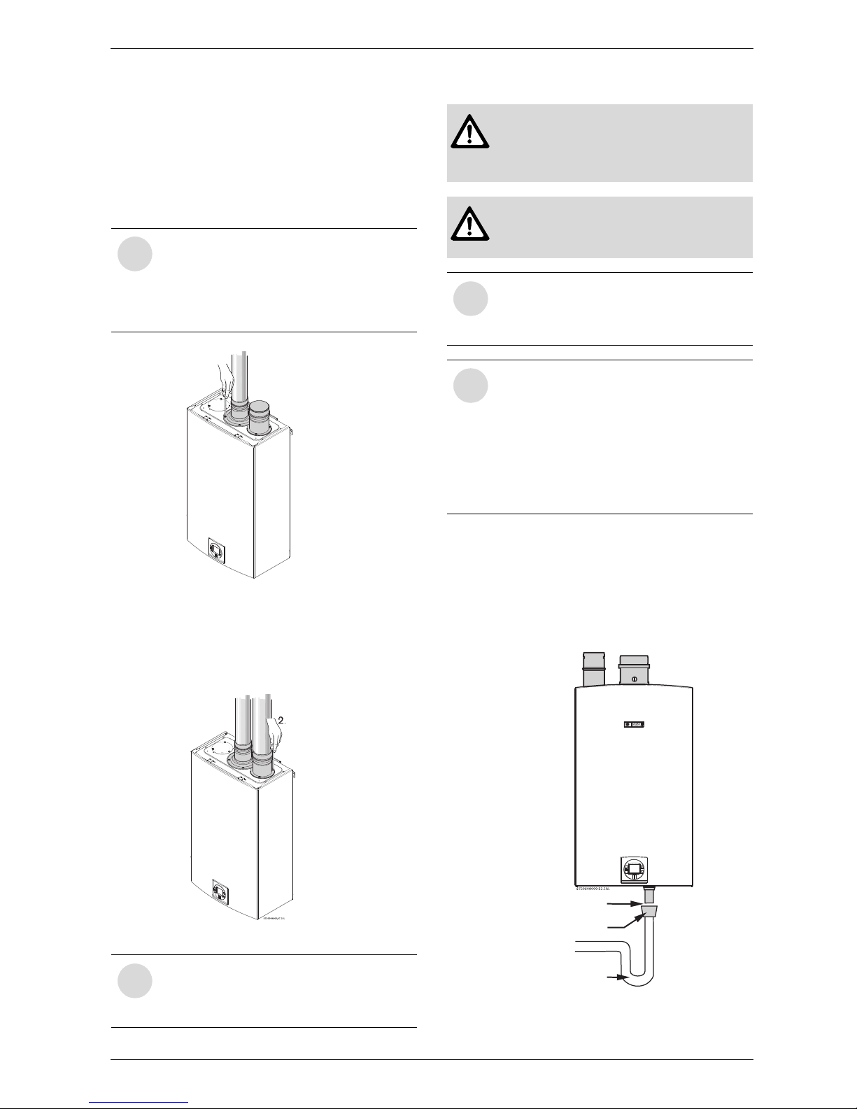
3.3.4 Vent connections
Attaching the exhaust and air inlet connection
adaptors to the top of the heater
B Attach the flue gas exhaust accessory to the top of
the unit Fig. 13 (position 1) using the 4 screws and
gasket provided, and fully insert vent pipe into the
accessory.
Fig. 15 Exhaust connection
B Attach the combustion air inlet accessory to the top
of the unit Fig. 14 (position 2) using the 3 screws and
gasket provided, and install 3" air intake pipe over the
accessory.
Fig. 16 Inlet connection
3.3.5 Connecting the condensate water drain
Appliance condensate drain installation
The appliance comes equipped with an internal
condensate drain and siphon. This drains condensation
formed in the secondary heat exchanger. Piping must
be installed under the condensate drain outlet on the
water heater and piped for disposal in accordance with
local codes.
Fig. 17 Appliance drain installation
i
NOTE: Vent pipe must be completely
vertical when inserting or blue gasket
inside exhaust accessory can become
displaced. Exhaust accessory can be
removed with vent pipe attached to check
gasket position.
i
NOTE: The combustion air accessory can
be installed on the top right or on the top
left side of the heater. The combustion air
inlet that is not used must be kept sealed.
6720608836-26.1Av
1.
Warning:
B Failure to properly install condensate
drain can damage the appliance and will
void the warranty.
Warning:
B Do not install condensate drain tubing in
areas where it may freeze.
i
The condensate must be disposed of in
accordance with local codes.
See chapter 3.12 “Filling the condensate
trap”.
i
Use materials approved by the authority
having jurisdiction. In the absence of other
authority, PVC, and CPVC pipe must
comply with ASTM D1785, F441 or
D2665. Cement and primer must comply
with ASTM D2564 or F493. For Canada,
use CSA or ULC certied PVC or CPVC
pipe, ttings and cement, see table 2.
Leave min. ¼" air gap
1 ½" x ½" PVC Reducer
Trap required
6 720 680 226
16
Installation instructions
External condensate drain installation
If an external condensate drain (installer supplied) must
be installed (Section 3.3.2), the following is
recommended:
• 1. Install condensate drain on a horizontal section of
the exhaust pipe as close to the heater as possible.
• 2. The condensate must be disposed of according to
local codes.
• 3. To install condensate drain in vent system, use
PVC 3" X 3" X 1.5" tee (part# 196278) and reduce
for drain connection.
Fig. 18 External condensate drain installation
3.3.6 Fan speed adjustment
! IMPORTANT INFORMATION:
Natural gas heaters with installation altitudes
below 2,000 ft above sea level disregard this
section.
Installation adjustment:
After installing the tankless water heater, the fan speed
values for minimum power (P2) and maximum power
(P1) may need adjustment due to variations in altitude
and vent pipe length. Failure to make necessary
adjustments to fan speed values may result in improper
operation of the appliance.
First calculate the total equivalent vent length. Use this
value to determine the appropriate fan speed values
found in table 12 and make any necessary adjustments.
After changing fan speed values, proceed to section
6.5
to confirm CO2 values are within specifed ranges.
Total vent length calculation
Note: See table 5 for maximum vent lengths.
B Determine the total length of all straight sections of
vent pipe and enter in table 10, line 1.
B Count the number of 90° elbows used, multiply by 5,
and enter that value in line 2. (Do not count 90°
elbows used as terminations on intake and
exhaust piping.)
B Count the number of 45° elbows used, multiply by 3,
and enter that value in line 3.
B Repeat steps 1 through 3 for air intake pipe and enter
those values in the intake section of table 10.
B Add line 4 from Exhaust to line 4 of Intake and enter
result in line 5.
This is the total equivalent vent length.
6720608836-09.2AL
Dispose of condensate in
accordance with local codes
4” Min.
Condensate drain
Fittings or Piping Equivalent
feet m
45 degree elbow 3 0.91
90 degree elbow 5 1.52
plastic pipe per foot 1 0.30
Table 9 Friction Loss Equivalent in piping and fittings
i
Note: If using concentric terminal include
pipe length that is part of the concentric
terminal.
6 720 680 226
Installation instructions
17
Concentric Pipe Example
Exhaust
• 3 - 3’ straight sections
• 1 - 2’ straight section
– Total length 11'
• 1 - 90° elbow.
Intake
• 2 - 3’ straight sections
• 1 - 2’ straight sections
– Total length 8'
• 3 - 45° elbow.
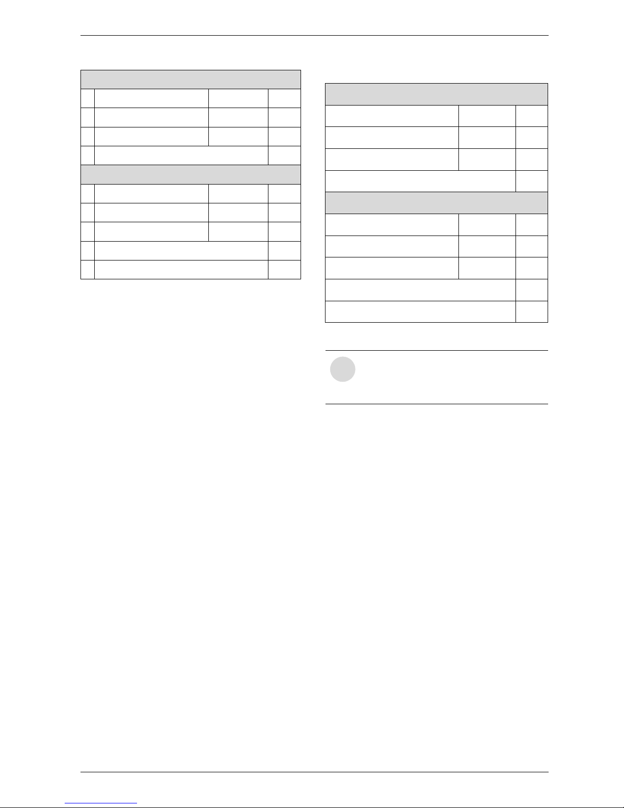
Summary
Exhaust
1
Straight section length __ =
____
2
90° elbows (qty) __ x 5 =
____
3
45° elbows (qty) __ x 3 =
____
4 Total:
____
Intake
1
Straight section length __ x 1 =
____
2
90° elbows (qty) __ x 5 =
____
3
45° elbows (qty) __ x 3 =
____
4
Total:
____
5
Total equivalent vent length =
____
Table 10Determining vent length combination (see
example in Table 11)
Exhaust
Straight section length (feet) 11 x 1 = 11
90° elbows (qty) 0 x 5 = 0
45° elbows (qty) 0 x 3 = 0
Total: 11
Intake
Straight section length (feet) 8 x 1 = 8
90° elbows (qty) 0 x 5 = 0
45° elbows (qty) 1 x 3 = 3
Total: 11
Total equivalent vent length = 22
Table 11 Determining vent length combination
example for concentric terminal
i
Total equivalent length must not exceed
62 ft for separate pipes.
Total equivalent length must not exceed
46 ft for concentric terminal.
6 720 680 226
18
Installation instructions
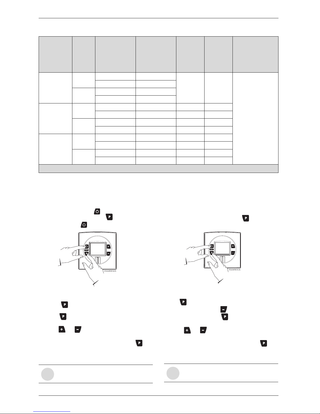
Adjusting minimum power fan speed (P2)
To select fan speed:
B Press ON/OFF button into OFF.
B Press and hold "Program" button and press
ON/OFF button to turn appliance ON.
Fig. 19
B As soon as '188' is displayed, release "Program"
button , and the display reads P2.
B Press to enter P2 adjustment. The current set-
ting will appear on the
display (factory default: 12).
B Press or to choose the fan speed suitable
with your installation, see table 12.
B Press and hold (± 5 sec.) “Program” button until
the display flashes, then the selected value is
memorized.
Adjusting maximum power fan speed (P1)
To select fan speed:
B Press ON/OFF button into OFF.
B Press and hold "Program" button and press
ON/OFF button to turn appliance ON.
Fig. 20
B As soon as '188' is displayed, release "Program" but-
ton , and the display reads P2.
B Press the minus button to display P1.
B Press “Program” button to enter P1 adjustment.
The current setting will appear on the display.
B Press or to choose the fan speed suitable
with your installation, see Table 12.
B Press and hold (± 5 sec.) “Program” button until
the display flashes, then the selected value is memorized.
Natural
Gas
Liquid
propane
Altitude
(above sea
level)
Vent
terminal
Total equivalent
vent length
1)
Minimum power
fan speed (P2)
Maximum
power fan
speed (P1)
Maximum
power fan
speed (P1)
0 - 2000 ft
(0 - 610 m)
Concentric
8 - 25 ft 12
No
modification
required
No
modification
required
For operation at eleva-
tions above 2,000 ft
(610 m) the equip-
ment ratings shall be
reduced at the rate of
4% for each 1,000 ft
(305 m) above sea
level
26 - 46 ft 13
Twin
system
8 - 37 ft 12
38 - 62 ft 13
2000 - 4500 ft
(610 - 1372 m)
Concentric
8 - 25 ft 14* 52* 52*
26 - 46 ft 14* 53* 53*
Twin
system
8 - 37 ft 13* 52* 52*
38 - 62 ft 14* 53* 53*
4500 - 8000 ft
(1372 - 2439 m)
Concentric
8 - 25 ft 14* 53* 53*
26 - 46 ft 16* 53* 53*
Twin
system
8 - 37 ft 14* 53* 53*
38 - 62 ft 15* 53* 53*
* Above 2000 ft, CO2 levels must be checked with a combustion gas analyzer, see section
6.5
for instructions.
Table 12 Fan speed adjustment
1) Full equivalent length (inlet + outlet piping + fittings)
i
Do set P2 to greather then 16.
i
Proceed directly to Section 6.5 to confirm
CO2 values are within range.

6 720 680 226
Installation instructions
19
Attention residents of the Commonwealth of Massachusetts:
In the Commonwealth of Massachusetts the following
regulation went into effect on 12/30/2005:
(a)For all side wall horizontally vented gas fueled
equipment installed in every dwelling, building or
structure used in whole or in part for residential
purposes, including those owned or operated by the
Commonwealth and where the side wall exhaust vent
termination is less than seven (7) feet above finished
grade in the area of the venting, including but not limited
to decks and porches, the following requirements shall
be satisfied:
1. INSTALLATION OF CARBON MONOXIDE
DETECTORS. At the time of installation of the side wall
horizontal vented gas fueled equipment, the installing
plumber or gasfitter shall observe that a hard wired
carbon monoxide detector with an alarm and battery
back-up is installed on the floor level where the gas
equipment is to be installed. In addition, the installing
plumber or gasfitter shall observe that a battery
operated or hard wired carbon monoxide detector with
an alarm is installed on each additional level of the
dwelling, building or structure served by the side wall
horizontal vented gas fueled equipment. It shall be the
responsibility of the property owner to secure the
services of qualified licensed professionals for the
installation of hard wired carbon monoxide detectors.
a.In the event that the side wall horizontally vented gas
fueled equipment is installed in a crawl space or an at
tic, the hard wired carbon monoxide detector with alarm
and battery back-up may be installed on the next
adjacent floor level.
b. In the event that the requirements of this subdivision
can not be met at the time of completion of installation,
the owner shall have a period of thirty (30) days to
comply with the above requirements; provided,
however, that during said thirty (30) day period, a
battery operated carbon monoxide detector with an
alarm shall be installed.
2.APPROVED CARBON MONOXIDE DETECTORS.
Each carbon monoxide detector as required in
accordance with the above provisions shall comply with
NFPA 720 and be ANSI/UL 2034 listed and IAS
certified.
3. SIGNAGE. A metal or plastic identification plate shall
be permanently mounted to the exterior of the building
at a minimum height of eight (8) feet above grade
directly in line with the exhaust vent terminal for the
horizontally vented gas fueled heating appliance or
equipment. The sign shall read, in print size no less than
one half (1/2) inch in size, "GAS VENT DIRECTLY
BELOW. KEEP CLEAR OF ALL OBSTRUCTIONS".
4. INSPECTION. The state or local gas inspector of the
side wall horizontally vented gas fueled equipment shall
not approve the installation unless, upon inspection, the
inspector observes carbon monoxide detectors and
signage installed in accordance with the provisions of
248 CMR 5.08(2)(a)1 through 4.
(b)EXEMPTIONS: The following equipment is exempt
from 248 CMR 5.08(2)(a)1 through 4:
1. The equipment listed in Chapter 10 entitled
"Equipment Not Required To Be Vented" in the most
current edition of NFPA 54 as adopted by the Board;
and
2. Product approved side wall horizontally vented gas
fueled equipment installed in a room or structure
separate from the dwelling, building or structure used in
whole or in part for residential purposes.
(c) MANUFACTURERS REQUIREMENTS - GAS
EQUIPMENT VENTING SYSTEM REQUIRED. When
the manufacturer of Product Approved side wall
horizontally mounted gas equipment provides a venting
system design or venting system components with the
equipment, the instructions provided by the
manufacturer for the installation of the equipment and
the venting shall include:
1. Detailed instructions for the installation of the venting
system or the venting system components: and
2. A complete parts list for the venting system design or
venting system.
(d)MANUFACTURER REQUIREMENTS - GAS
EQUIPMENT VENTING SYSTEM NOT PROVIDED.
When the manufacturer of a product approved side wall
horizontally vented gas fueled equipment does not
provide the parts for the venting of flue gases, but
identifies "special venting systems," the following
requirements shall be satisfied by the manufacturer:
1. The referenced "special venting system" instructions
shall be included with the appliance or equipment
installation instructions; and
2. The "special venting systems" shall be product
approved by the Board, and the instructions for that
system shall include a parts list and detailed installation
instructions.
(e) A copy of all installation instructions for all products
approved side wall horizontally vented gas fueled
equipment, all venting instructions, all parts lists for
venting instructions, and/or all venting design
instructions shall remain with the appliance or
equipment at the completion of the installation.
6 720 680 226
20
Installation instructions
3.4 Combustion air requirements
Twin pipe and Concentric pipe
The water heater is designed as a sealed combustion
appliance. It is recommended that the combustion air
be provided by a dedicated 3” or 4” pipe from the
outside (twin pipe) or by connecting to the Concentric
vent kit (see Fig. 8). The combustion air pipe may be
PVC or any other rigid sealed 3" or 4" pipe. The
combustion air piping must pitch down 1/4 inch per
foot towards termination to prevent rain water from
entering the appliance. In twin pipe penetrations,
combustion air inlet, whether terminating vertically or
horizontally, must be located in such a manner as
to provide a minimum 3 foot clearance from the
exhaust vent terminator. See Fig. 9 and 10 Letter I,
page 12.
For the maximum length of the combustion air
pipe, see Tables 5 & 6.
Single pipe
Note: This appliance requires 9950 cubic feet of
available combustion air, or a minimum of 1243
square feet of space with an 8 foot ceiling to
operate. If the large amount of air space, which
equates to about half of most average sized
homes, is not available, the appliance must pull
air from the outside (see twin pipe above).
Although it is permissible to draw combustion air from
the inside, it is not the manufacturer’s recommended
installation method. Always install a 3 inch 90° elbow on
the top of the combustion air inlet adaptor to prevent
foreign objects from falling into the unit.
If a single pipe installation is utilized, follow guidelines
below for providing adequate combustion air for the
water heater as well as any other appliances that may
consume air in the same space. Always follow local
codes if they are more stringent and regulations.
• Appliances located in unconfined spaces:
– a) An unconfined space is one whose volume is
greater than 50 cubic feet (1.42 cubic meter) per
1000 Btu per hour (292.81 Watts) of the
combined rating of all appliances installed in the
space. That would be 9950 cubic feet (281.8
cubic meters) for the water heater alone.
– b) In unconfined spaces in buildings of
conventional frame, masonry, or metal
construction, infiltration air is normally adequate to
provide air for combustion.
• Appliances located in confined spaces:
The confined space must be provided with two permanent openings, one commencing within 12 inches
(304.8mm) of the top and one commencing within
12 inches (304.8mm) of the bottom of the enclosure.
Each opening must have a minimum free area of one
square inch per:
– 1000 Btu/hr (292.81 Watts) if all air is taken from
inside the building
– 2000 Btu/hr (585.62 Watts) if all air is taken from
the outside by horizontal ducts
– 4000 Btu/hr (1171.24 Watts)if all air is taken from
the outside by direct openings or vertical ducts
Or the confined space must be provided with one
permanent opening or duct that is within 12 inches
(304.8mm) of the ceiling of the enclosure. This opening
must have a minimum free area of one square inch per:
– 3000 Btu/hr (878.43 Watts) if all air is taken from
the outside by a direct opening or vertical duct.
Louvers, grills and screens have a blocking effect, when
used, increase the sizes of your openings by 300% for
wood louvers (as wood type will reduce the free air by
75%) and 43% for metal louvers (as metal will reduce
the free air by 30%). Refer to the National Fuel Gas
Code for complete information. In buildings of tight
construction all air should be taken from outside.
Warning: In areas where outside
temperatures routinely come close to
freezing, sealed combustion operation
is required. Use a concentric
termination or separate terminations for
combustion and vent, which must be
installed on the same wall or roof
surface, however never facing the
direction of prevailing winds. Failure to
do so may result in heat exchanger
freezing up and bursting. This failure is
not covered under the manufacturer's
warranty.
Warning: When installed in an
environment where corrosive chemicals
or dirty air (e.g. hair salons, car washes)
are present the twin pipe system is
required.
Warning: Terminations must prevent
rain and debris from entering the
combustion air and exhaust vent piping.
 Loading...