

BOSCH HMV3022U, HMV3052U, HMV3062U Installation Manual
Microwave
Installation Manual
300 SERIES
HMV3052U HMV3062U HMV3022U
Table of Contents
Installation instructions
Safety Definitions .......................................................... 2
IMPORTANT SAFETY INSTRUCTIONS ........................ 3
Appliance Handling Safety ................................................. 3
Safety Codes and Standards ............................................. 3
State of California Proposition 65 Warnings ................... 3
Electric Safety ....................................................................... 3
Microwave Safety ................................................................. 3
Related Equipment Safety .................................................. 4
Checklist for Installation ............................................... 5
Before You Begin ........................................................... 5
Removing Packaging .......................................................... 5
Tools and Parts Needed ..................................................... 5
Parts Included ....................................................................... 6
Location requirements ......................................................... 6
Power Requirements ........................................................... 7
Electrical Installation ..................................................... 7
4XHVWLRQV"
Install Appliance ............................................................ 8
Removing the mounting plate ........................................... 8
Finding the wall studs ......................................................... 8
Possible wall stud configurations ..................................... 8
Attaching the mounting plate to the wall ......................... 9
Adapting microwave blower ........................................... 10
Preparing cabinet .............................................................. 12
Mounting the microwave oven ....................................... 13
Hood exhaust ..................................................................... 14
Testing Operation ........................................................ 15
®
Bosch
Before Calling Service ...................................................... 16
Data Plate ........................................................................... 16
Service ................................................................................ 16
Parts and Accessories ..................................................... 16
Support ........................................................... 16
ZZZERVFKKRPHFRP
0DLQ6WUHHW6XLWH
,UYLQH&$
:HORRNIRUZDUGWRKHDULQJIURP\RX
Safety Definitions
9 WARNING
This indicates that death or serious injuries may
occur as a result of non-observance of this warning.
9 CAUTION
This indicates that minor or moderate injuries may
occur as a result of non-observance of this warning.
NOTICE: This indicates that damage to the appliance or property may occur as a result of non-compliance with this advisory.
Note: This alerts you to important information and/or tips.
2

9 IMPORTANT SAFETY INSTRUCTIONS
READ AND SAVE THESE INSTRUCTIONS
IMPORTANT SAFETY INS READ AND SAVE THESE INSTRUCTIONS
INSTALLER: LEAVE THESE INSTRUCTIONS WITH THE
APPLIANCE AFTER INSTALLATION IS COMPLETE.
IMPORTANT: SAVE THESE INSTRUCTIONS FOR THE
LOCAL ELECTRICAL INSPECTOR'S USE.
WARNING
Electric Safety
WARNING
Before you plug in an electrical cord or turn on power
supply, make sure all controls are in the OFF position.
If the information in this manual is not followed exactly,
fire or shock may result causing property damage or
personal injury.
WARNING
Do not repair, replace or remove any part of the
appliance unless specifically recommended in the
manuals. Improper installation, service or maintenance
can cause injury or property damage. Refer to this
manual for guidance. All other servicing should be done
by a qualified technician.
Appliance Handling Safety
Unit is heavy and requires at least two people or proper
equipment to move.
Do not lift appliance by door handle.
Hidden surfaces may have sharp edges. Use caution
when reaching behind or under appliance.
Safety Codes and Standards
This appliance complies with the latest version of one or
more of the following standards:
▯ CAN/CSA C22.2 No. 61 - Household Cooking Ranges
▯ UL 858 - Household Electric Ranges
▯ CAN/CSA C22.2 No. 150 - Microwave Ovens
▯ UL 923 - Microwave Cooking Appliances
▯ UL 507 - Electric Fans
▯ CAN/CSA C22.2 No. 113 - Fans and Ventilators
▯ CSA C22.2 No. 64 - Household Cooking and Liquid-
Heating Appliances
▯ UL 1026 - Electric Household Cooking and Food
Serving Appliances
It is the responsibility of the owner and the installer to
determine if additional requirements and/or standards
apply to specific installations.
State of California Proposition 65 Warnings
WARNING
This product contains chemicals known to the State of
California to cause cancer, birth defects or other
reproductive harm.
For appliances equipped with a cord and plug, do not
cut or remove the ground prong. It must be plugged into
a matching grounding type receptacle to avoid electrical
shock. If there is any doubt as to whether the wall
receptacle is properly grounded, the customer should
have it checked by a qualified electrician.
If required by the National Electrical Code (or Canadian
Electrical Code), this appliance must be installed on a
separate branch circuit.
Installer – show the owner the location of the circuit
breaker or fuse. Mark it for easy reference.
Before installing, turn power OFF at the service panel.
Lock service panel to prevent power from being turned
ON accidentally.
Be sure your appliance is properly installed and
grounded by a qualified technician. Installation, electrical
connections and grounding must comply with all
applicable codes.
Microwave Safety
PRECAUTIONS TO BE OBSERVED BEFORE AND
DURING SERVICING TO AVOID POSSIBLE EXPOSURE
TO EXCESSIVE MICROWAVE ENERGY
▯ Do not operate or allow the oven to be operated with
the door open.
▯ Make the following safety checks on all ovens to be
serviced before activating the magnetron or other
microwave source, and make repairs as necessary:
1.
Interlock operation
2.
Proper door closing
3.
Seal and sealing surfaces (arcing, wear, and other damage)
4.
Damage to or loosening of hinges and latches
5.
Evidence of dropping or abuse
▯ Before turning on microwave power for any service
test or inspection within the microwave generating
compartments, check the magnetron, wave guide or
transmission line, and cavity for proper alignment,
integrity, and connection.
▯ Any defective or misadjusted components in the
interlock, monitor, door seal, and microwave
generation and transmission systems shall be
repaired, replaced, or adjusted by procedures
described in this manual before the oven is released
to the owner.
▯ A microwave leakage check to verify compliance with
the Federal Performance Standard should be
performed on each oven prior to release to the owner.
3

9 IMPORTANT SAFETY INSTRUCTIONS
READ AND SAVE THESE INSTRUCTIONS
GROUNDING INSTRUCTIONS
This appliance must be grounded. Grounding reduces
the risk of electric shock by providing a safe pathway for
electric current in the event of a short circuit.
This appliance is equipped with a cord having a
grounding wire with a grounding plug. The plug must be
plugged into an outlet that is properly installed and
grounded.
WARNING
Improper grounding can result in a risk of electric shock.
Consult a qualified electrician if the grounding
instructions are not completely understood, or if doubt
exists as to whether the appliance is properly grounded.
Do not use an extension cord. If the power supply cord is
too short, have a qualified electrician install an outlet
near the appliance.
Related Equipment Safety
Remove all tape and packaging before using the
appliance. Destroy the packaging after unpacking the
appliance. Never allow children to play with packaging
material.
Never modify or alter the construction of the appliance.
For example, do not remove leveling legs, panels, wire
covers or anti-tip brackets/screws.
WARNING
To reduce the risk of fire, use only metal ductwork.
CAUTION
For general ventilating use only. Do not use to exhaust
hazardous or explosive materials and vapors.
4
Checklist for Installation
Use this checklist to verify that you have completed each
step of the installation process. This can help you avoid
common mistakes.
Refer to detailed instructions for each step in the
sections following this checklist.
1.
Before installing the appliance, be sure to verify the
cabinet dimensions are correct for your appliance and
that the required electrical connections are present.
Make sure the electrical cord provided on the
appliance is able to reach to the point of connection.
Sections: Location requirements, Electrical installation
2.
Move the appliance into place in front of the cabinet opening.
Section: Removing Packaging
3.
Remove packaging materials, leaving the bottom packaging on the appliance to avoid damage to the floor.
Section: Removing Packaging
4.
Remove the mounting plate from the rear of the appliance.
Section: Install Appliance - Removing the mounting
plate
5.
Find wall studs.
Section: Install Appliance - Finding the wall studs
6.
Attach the mounting plate to the wall.
Section: Install Appliance - Attaching the mounting
plate to the wall
7.
Adapt the microwave blower.
Section: Install Appliance - Adapting the microwave
blower
8.
Prepare the cabinet for mounting.
Section: Install Appliance - Preparing cabinet
9.
At least two persons are needed to lift the appliance; tilt and hook the appliance to the holding plate.
Section: Install Appliance - Mounting the microwave
oven
10.
Push the appliance all the way into place and fasten
the holding screws through top cabinet holes.
Section: Install Appliance - Mounting the microwave
oven
11.
Use correct hood exhaust.
Section: Install Appliance - Hood exhaust
12.
Test the microwave oven for proper functioning.
Section: Testing operation
Always read and follow the complete installation
instructions contained in this manual.
Before You Begin
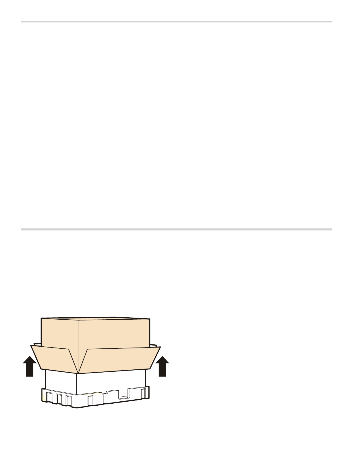
Removing Packaging
1.
Remove filter, accessories and hardware. Do not remove the Styrofoam protecting the front of the oven.
2.
Fold back all four carton flaps fully against carton sides. Then carefully roll the oven and carton over onto the top side. The oven should be resting in the Styrofoam.
3.
Pull the carton up and off the oven.
Tools and Parts Needed
▯ Philips head screwdriver
▯ Pencil
▯ Ruler or tape measure and straight edge
▯ Drill
▯ Drill bits: 3/16”, 1/2”, 5/8”
▯ Gloves
▯ Saw (saber, hole or keyhole)
▯ Stud finder or hammer
▯ Safety goggles
▯ Level
▯ Duct and masking tape
Optional tools
▯ Carpenter square
▯ Tin snips (to cut damper and to remove knockouts)
▯ Scissors (to cut cabinet template)
▯ Filler blocks or scrap wood pieces (for recessed
bottom cabinet installations)
4.
Cut the middle of the outer protective plastic bag to remove the mounting plate.
5
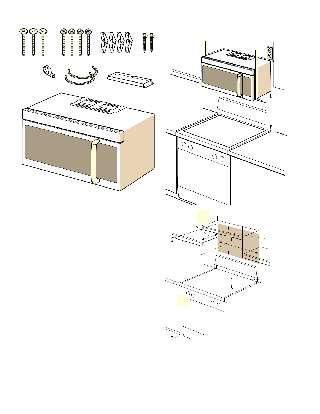
Parts Included
Location requirements
Installation dimensions
$%&
'
()*
You will find the installation hardware contained in packet
with the unit. Check to make sure you have all these
parts:
A Top mounting bolts:
Self-aligning machine screws
]”-28x3]”
ë
PP
PLQ
PLQPP
PD[PP
B Toggle bolts - 3/16”x3”
C Wall mounting hardware:
Toggle wings
D Wood screws ]”x2”
E Power chord strap
F Nylon grommet (for metal cabinets)
G Exhaust adaptor
Not shown:
▯ Top cabinet template
▯ Mounting plate (attached to the back of the microwave
oven)
▯ Aluminum grease filters
▯ Charcoal filter (factory-fitted in the microwave oven)
PLQ
PP
FDELQHW
RSHQLQJ
ZLGWK
PLQ
PP
PLQ
PP
PLQ
PP
)RURSWLPDOSHUIRUPDQFHDQG
UHOLDELOLW\WKHPDQXIDFWXUHU
UHFRPPHQGV²FOHDUDQFH
DOWKRXJKWKHPLQLPXPDOORZDEOH
FOHDUDQFHLVQRWHG
6
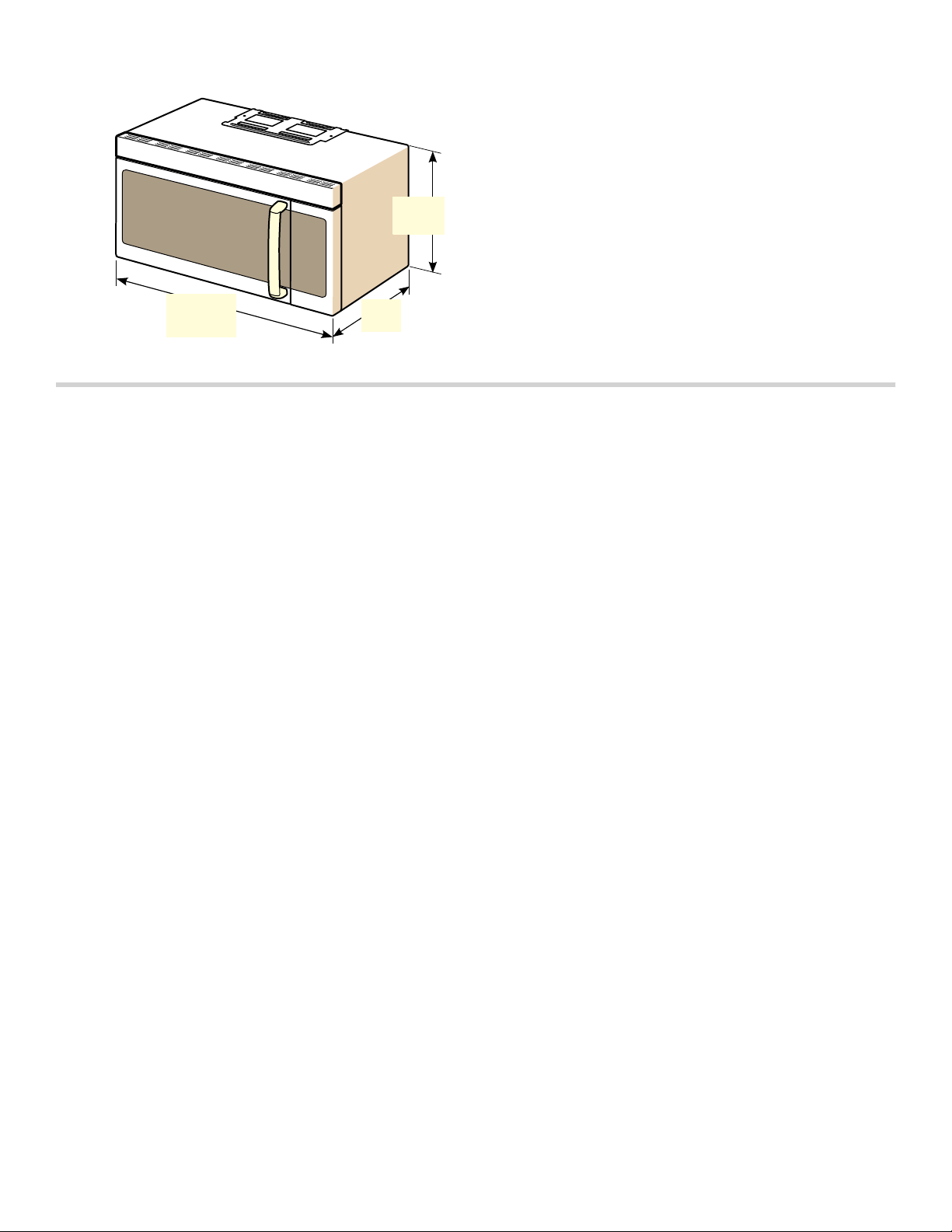
Appliance dimensions
PP
Power Requirements
The outlet must be properly grounded in accordance with
all applicable codes.
It can be installed inside the cabinet above the
appliance.
PP
PP
Electrical Installation
Electrical Requirements:
▯ a three prong grounded outlet
▯ 120 V, 60 Hz, AC only
▯ 20 Amp electrical supply with a fuse or a circuit
breaker
This product must be connected to a supply circuit of the
proper voltage and frequency. Wire size must conform to
the requirements of the National Electric Code or the
prevailing local code for this rating. The power supply
cord and plug should be brought to a separate 20-amp
branch circuit single grounded outlet. The outlet box
should be located inside the cabinet above the appliance
(see section Location Requirements). The outlet box and
supply circuit should be installed by a qualified
electrician and conform to the National Electrical Code or
the prevailing local code.
The voltage used must be the same as specified on this
microwave oven. Using a higher voltage is dangerous
and may result in a fire or oven damage. Using a lower
voltage will cause slow cooking. The dealer is not
responsible for any damages resulting from the use of
the oven with any voltage other than specified.
7
Install Appliance
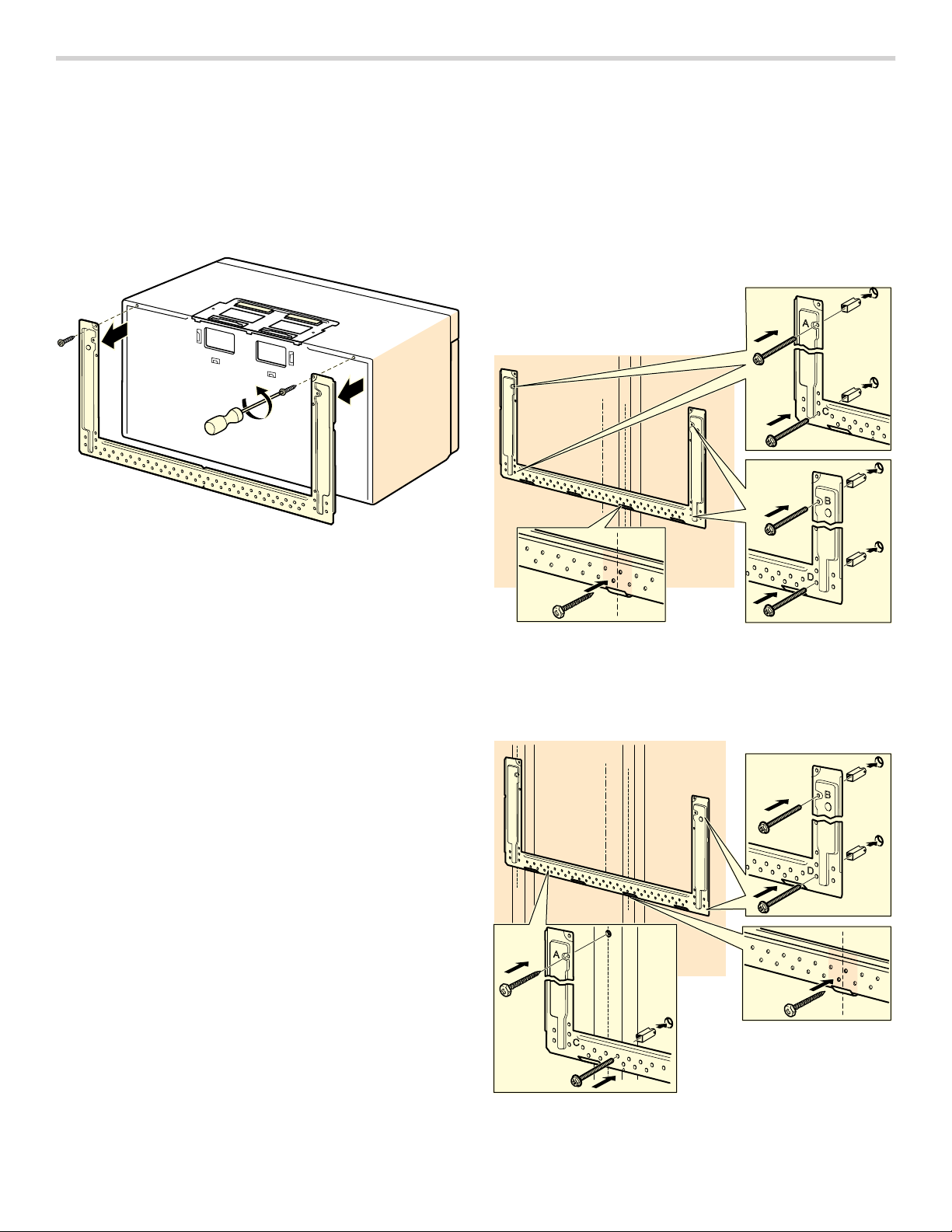
Removing the mounting plate
Note: To avoid possible damage to the work surface or
to the bottom of the appliance, cover the work surface.
1.
Remove any remaining contents from the microwave oven cavity.
2.
Remove the screws from the mounting plate.
The mounting plate will be used as the rear wall
template and for mounting.
3.
Reinstall the screws into the holes where they were removed.
Note: To avoid damage to the microwave oven, do not grip or use the door or door handle while the microwave oven is being handled.
Finding the wall studs
Note: The microwave must be connected to at least one
wall stud. If no wall studs exist within the cabinet
opening, do not install the microwave oven.
1.
Locate the edges of the wall studs within the cabinet opening by using:
- a stud finder or
- a hammer (tapping lightly across the mounting
surface to find a solid sound).
2.
Place a mark halfway between the edges and draw a line down the center of the studs (See possible wall studs configuration).
Possible wall stud configurations
These depictions show examples of preferred installation
configurations with the mounting plate.
Note: Care must be taken when drilling holes. Electrical wires may be concealed behind the wall covering and contact with them could result in electrical shock.
No wall studs at corner holes
If wall stud is within 6¼" (159 mm) of the vertical
centerline, only Room Venting (recirculation) or Roof
Venting installations can be done.
Wall stud at one corner hole
8
Wall studs at both corner holes
Attaching the mounting plate to the wall
Aligning the mounting plate
9 CAUTION
Wear gloves to avoid cutting fingers on sharp
edges.
Note: Make sure the cabinet bottom is level.
1.
Draw a vertical line on the wall at the center of the cabinet space.
2.
Use the mounting plate as a template and place it on the wall, making sure that the tabs are touching the bottom of the cabinet or the level line.
$ %
'&
3.
Line up the notch and centerline of the mounting plate to the centerline on the wall.
4.
While holding the mounting plate, draw circles on the wall at holes A, B, C and D.
Note: If neither A, B, C nor D is in a stud, find a stud somewhere in the bottom area of the mounting plate and draw a fifth circle to line up with the stud.
It is important to use at least one wood screw mounted
firmly in a stud to support the weight of the microwave.
5.
Set the mounting plate aside.
6.
Drill holes on the circles:
▯ 3/16” (5 mm) holes for wood screws (stud)
▯ 5/8” (16 mm) holes for toggle bolts (no stud)
Attaching the mounting plate (no wall studs at corner holes)
1.
Insert the bolts into the mounting plate through the holes designated.
$ %
'&
9
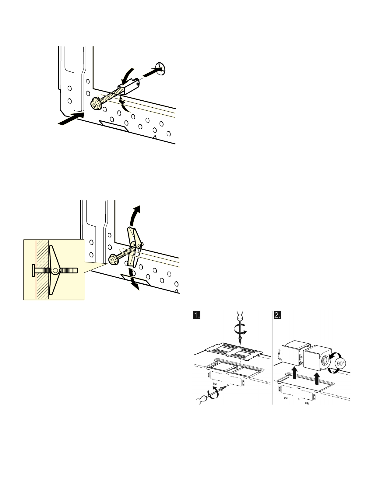
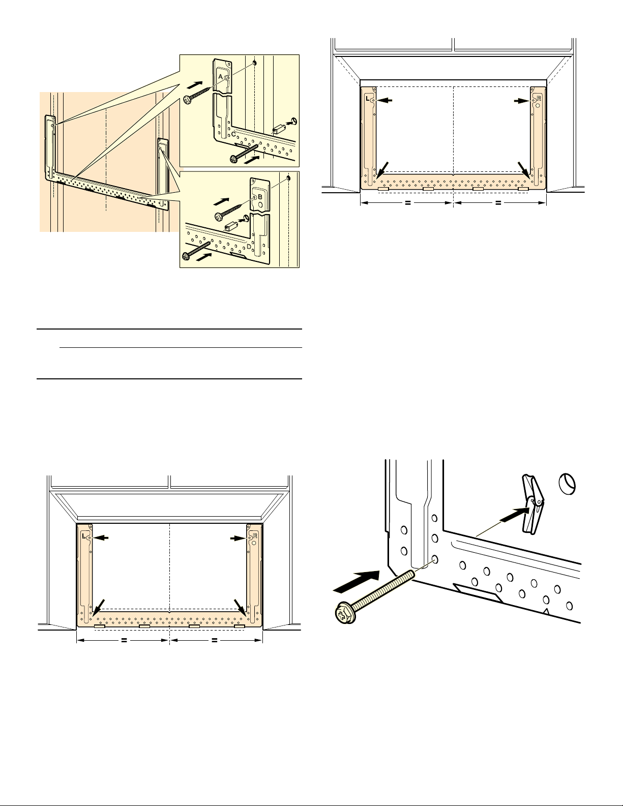
2.
Attach toggle wings from the back of the mounting plate onto each bolt. Leave enough space for toggle wings to go through the wall and to open.
3.
Place the mounting plate against the wall and make sure tabs are touching the bottom of the cabinet or the level line (see "Aligning the mounting plate").
4.
Push the bolts through the drywall and finger tighten the bolts to make sure toggle wings have opened against drywall.
Attaching the mounting plate (wall stud at one corner hole)
1.
Insert the bolts and the wood screws into the mounting plate through the holes designated.
2.
Attach toggle wings from the back of the mounting plate onto each bolt. Leave enough space for toggle wings to go through the wall and to open.
3.
Place the mounting plate against the wall and make sure tabs are touching the bottom of the cabinet or the level line (see "Aligning the mounting plate").
4.
Push the bolts through the drywall and finger tighten the bolts to make sure toggle wings have opened against drywall.
5.
Confirm that the plate is properly centered and level.
6.
Securely tighten all screws and bolts.
Attaching the mounting plate (wall studs at both corner holes)
1.
Insert the wood screws into the mounting plate through the holes designated.
2.
Place the mounting plate against the wall and make sure tabs are touching the bottom of the cabinet or the level line (see "Aligning the mounting plate").
3.
Confirm that the plate is properly centered and level.
4.
Securely tighten all screws.
5.
Confirm that the plate is properly centered and level.
6.
Securely tighten all screws, including the fifth wood screw in the bottom area of the mounting plate.
Adapting microwave blower
This microwave is shipped assembled for Room Venting
Installation. The blower unit is already in place and must
not to be adapted.
Adapting microwave blower for roof venting
1.
Remove and save the screws holding the blower motor and the blower plate. Lift up the blower plate and put it aside.
2.
Carefully pull out the blower unit and rotate 90º so that fan blade openings are facing out the top of the microwave.
10
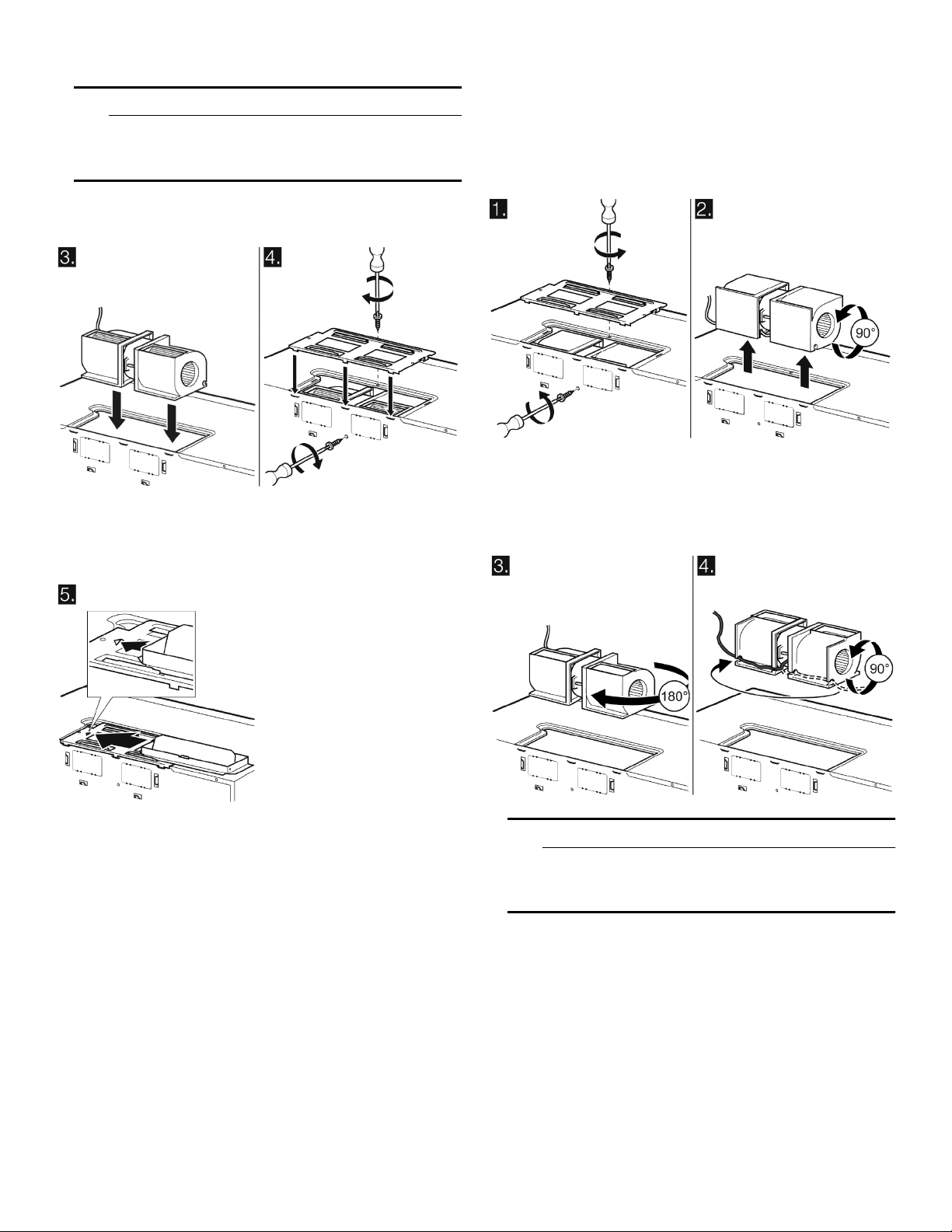
3.
Place the blower unit back into the opening.
9 CAUTION
Do not pull or stretch the blower unit wiring. Make
sure the wires are not pinched, and that they are
properly secured.
4.
Replace the blower plate and secure with the screws removed in step 1.
5.
Attach the exhaust adapter to the top of the blower plate by sliding it into the guides. Push in securely until it is in the locking tabs. Make sure the damper hinge swings freely.
Adapting microwave blower for wall venting
1.
Remove and save the screws holding the blower motor and the blower plate. Lift up the blower plate and put it aside.
2.
Carefully pull out the blower unit and rotate 90º so that fan blade openings are facing out the top of the microwave.
3.
Rotate the blower unit counterclockwise 180º.
4.
Gently remove the wires from the grooves. Reroute the wires through the grooves on other side of the blower unit. Rotate blower unit 90º so that fan blade openings are facing out the back of the microwave.
9 CAUTION
Do not pull or stretch the blower unit wiring. Make
sure the wires are not pinched, and that they are
properly secured.
5.
Place the blower unit back into the opening.
6.
Replace the blower plate and secure with the screws removed in Step 1.
7.
Use tin snips to cut and remove knockouts from the rear plate of the microwave oven. Discard knockouts. Be careful not to distort the plate.
11
 Loading...