

Bosch Heatronic 4000 Installation & Operating Instructions Manual
Features
•
Control and monitor up to 4 boilers, condensing,
non-condensing, or a mix
• BACnet
• Programmable Scheduling
• DHW priority
• Outdoor Temperature Reset
•
• Compatible with NG, LPG & Oil Burners
• Programmed boiler default parameters
®
IP or Modbus® Compatible
Compatible with modulating, singe stage, two stage
and dual fuel burners
The Heatronic 4000 is designed to operate up to four boilers to
accurately maintain a target water temperature. The Heatronic
4000 operates both condensing & non-condensing boilers that
are either modulating, single stage two stage or dual fuel to
provide a flexible, cost effective mixed boiler plant solution
with better system performance.
The target water temperature is based on outdoor temperature
reset or a fixed setpoint for space or process heating applications.
Additional loads supplied by the Heatronic 4000 include
domestic hot water heating. Boiler equal run-time rotation,
stand-by primary pump operation & pump exercising all
increase boiler plant reliability.
The Heatronic 4000 communicates with a Building Automation
System (BAS) using BACnet® IP or Modbus® for remote
monitoring & adjustment capability.
4 boiler control, DHW, BACnet and Modbus
Heatronic 4000
IO Heatronic 4000 2014/04 en-us
Installation/Operating instructions (IO)
To avoid serious personal injury or property damage:
•
Read Manual and all product labels BEFORE using this product and follow all safety and
use information. Failure to do so could result in personal injury or property damage.
•
Do not use unless you know the safe and proper operation of equipment required for
installation.
•
It is the installers responsibility to ensure that this product is safely installed according
to all applicable codes and standards.
Table of Contents
Sequence of Operation ...........................................................................3
Boiler Setup ..............................................................................................3
System Setup ...........................................................................................6
Boiler Plant Operation .........................................................................8
Dual Fuel Operation ...........................................................................10
Outdoor Temperature Reset Operation .....................................10
Setpoint Operation .............................................................................12
Energy Management System (EMS) Operation .......................12
Indirect Domestic Hot Water (IDHW) Operation .....................13
Dedicated Domestic Hot Water (DDHW) Operation .............16
Building Automation System (BAS) Operation ........................16
Pump Operation ..................................................................................17
Combustion Air Damper & DHW Recirculation .......................19
Setting the Schedule ..........................................................................19
Time Clock ..............................................................................................20
Installation ................................................................................................. 21
Installation Location ...........................................................................21
Control Wiring .......................................................................................22
Sensor Installation & Wiring ............................................................25
EMS, Modbus
®
& BACnet® Connections .......................................28
Testing the Sensor Wiring ................................................................29
Testing the Control Wiring ............................................... 30
Control Settings .......................................................................................31
Access Level ...........................................................................................31
DIP Switch Settings .............................................................................31
User Interface ............................................................................................32
Display & Symbols ...............................................................................32
Navigating the Display ......................................................................33
View Menu ............................................................................................33
Setup Menu ..........................................................................................35
Source # Menu ......................................................................................41
BAS Menu ...............................................................................................43
Monitor # Menu ....................................................................................45
Monitor Menu ......................................................................................46
Time Menu ...........................................................................................48
Schedule Menu ....................................................................................49
Toolbox Menu ......................................................................................50
Manual Override .................................................................................52
Troubleshooting ......................................................................................54
Error Messages .....................................................................................54
Technical Data ....................................................................................57
Limited Warranty .....................................................................................57
Appendix: Bosch / Buderus Boiler Model Default Table ................... 58
Understanding Safety Information
This is a safety-alert symbol. The safety alert
symbol is shown alone or used with a signal word
(WARNING or CAUTION), a pictorial and/or a safety
message to identify hazards.
When you see this symbol alone or with a signal
word on your equipment or in this Manual, be alert to
the potential for death or serious personal injury.
This pictorial alerts you to electricity,
electrocution, and shock hazards.
To avoid serious personal injury or property damage:
•
Read Manual and all product labels BEFORE using this product and follow all safety and use
information. Failure to do so could result in personal injury or property damage.
• Do not use unless you know the safe and proper operation of equipment required for installation.
•
It is the installers responsibility to ensure that this product is safely installed according to all
applicable codes and standards.
Radio Frequency Interference
The installer must ensure that this control & its wiring are
isolated &/or shielded from strong sources of electromagnetic
noise. Conversely, this Class B digital apparatus complies
with Part 15 of the FCC Rules & meets all requirements of
the Canadian Interference-Causing Equipment Regulations.
However, if this control does cause harmful interference to
This symbol identifies hazards which,
if not avoided, could result in death or
serious injury.
This symbol identifies hazards which,
if not avoided, could result in minor or
moderate injury.
This symbol identifies practices, actions, or
failure to act which could result in property
damage or damage to the equipment.
radio or television reception, which is determined by turning
the control off & on, the user is encouraged to try to correct
the interference by re-orientating or relocating the receiving
antenna, relocating the receiver with respect to this control,
&/or connecting the control to a different circuit from that to
which the receiver is connected.
Heatronic 4000
2 of 60
BTC461503101C | 6720810369 (2018/03)

Sequence of Operation
-------------------------------------------
-------------------------------------------
----------------------------------
---------------------------
------------------------------
---------------------------------------------
--------------------------------------------
----------------------------------------
----------------------------------------------
Boiler (Source (#) Menu) Setup & Operation
The Heatronic 4000 is able to operate up to four boilers as a
heat source. Each boiler is independently configured allowing
for maximum plant flexibility.
Boiler Enable
This setting selects whether the boiler is operational or not.
OFF
The boiler is disabled & will not be included in the plant
operation.
AUTO
The boiler is enabled & will be included in the plant
operation.
Copy Boiler 1
Many boiler installations will have multiple identical boilers.
To reduce the number of settings required, certain settings
of boiler 1 are copied to boiler 2 by setting the Boiler 2 Copy
setting to Boil1. Copy settings are also available for boiler 3
& boiler 4.
OFF
The settings from boiler 1 are not copied. This allows for
individual boiler settings.
Boil
The settings from boiler 1 are copied.
-------------------------------------------
-------------------------------------------
Bosch / Buderus Boiler
This setting selects whether the boiler is one of the pre-defined
Bosch / Buderus boiler models.
YES
The boiler is one of the available Bosch / Buderus models. The
Bosch / Buderus Model setting allows for selection of one of
the pre-defined Bosch / Buderus models.
NO
The boiler is not one of the pre-defined Bosch / Buderus
models.
Bosch / Buderus Boiler Model
When a Bosch / Buderus boiler model is selected, the control
loads default values for the majority of the boiler settings. Some
of the defaults can be adjusted while others are hard-coded.
Refer to the Appendix on page 58 in this manual for a listing of
the different Bosch / Buderus boiler models with their respective
pre-defined default values.
Bosch / Buderus Fuel Type
Some of the Bosch / Buderus boiler models support multiple
fuel options.This setting selects what fuel(s) the applicable
Bosch / Buderus boiler model is to use. As with single fuel type
Bosch / Buderus boiler models, the control loads defaults for
the majority of the boiler settings.
GAS
The boiler fuel is gas.
OIL
The boiler fuel is oil.
DUAL
The boiler includes both gas and oil as a fuel type.
----------------------------------
---------------------------
------------------------------
Boiler Type
The Heatronic 4000 has four different boiler types to choose from.
Use the Boil TYPE setting to select one of the following:
MOD
The modulating output operates a modulating boiler by controlling
the burner firing rate. The Stage 1 relay is also used to give
a boiler enable to allow the modulating boiler to go through
ignition sequence. The Stage 1 relay may not be required on
all modulating boilers.
STG
The Stage 1 relay operates a single, stage boiler by cycling
the burner stage on & off.
STG
The Stage 1 & Stage 2 relays operate a single, two stage boiler
by cycling the burner stages on & off.
EMS
The modulating output operates a boiler that interprets an analog
input signal as a target temperature. The EMS Temperature
Minimum, EMS Temperature Maximum and, if applicable, Vdc
Signal Minimum define the analog signal and temperature
rails. The Stage 1 relay is also used to give a boiler enable
to allow the EMS temperature boiler to go through ignition
sequence. The Stage 1 relay may not be required on all EMS
temperature boilers.
Condensing
This setting selects whether the boiler is condensing or noncondensing & defines what boiler group it is part of.
NO
The boiler is non-condensing & is part of the non-condensing
boiler group.
YES
The boiler is condensing & is part of the condensing boiler
group.
Modulating Type
The MOD TYPE setting selects the analog output signal used
for modulating (MOD) and temperature (EMS) boiler types.
The modulating output is 0-10 V (dc).
The modulating output is 4-20 mA.
The 4-20 mA output can be converted to a 0 - 135 Ω output
using a 0 - 135 Ω Converter 005. Refer to the Modulating Boiler
Wiring section of the Control Wiring section.
Fire Delay
The Fire Delay sets the time it takes for the boiler to
generate flame from the time the boiler turns on.
---------------------------------------------
--------------------------------------------
----------------------------------------
----------------------------------------------
Boiler Con tact Closed
Fire Delay
Burner On
Time
BTC461503101C | 6720810369 (2018/03)
3 of 60
Heatronic 4000

Modulation Delay
---------------------------------------
---------------------------------------------
-----------------------
-------------------------------------------
---------------------------------------
-----------------------------------------------------
---------------------------------------
The MOD DELAY is the time that the boiler burner must hold
the modulation of the boiler at a minimum before allowing it to
modulate any further.
Boiler Mass
---------------------------------------------
The Boil MASS setting selects the thermal mass characteristics
of each boiler. Operation of the boiler can become unstable if the
incorrect Boiler Mass setting is chosen. A key sign of unstable
boiler operation is that the flame will continue to increase & then
decrease in short periods of time. By choosing a lower boiler
mass setting, the boiler response will become more stable.
LOW GB Series
The LO setting is selected if the boiler that is used has a low
thermal mass. This means that the boiler has very small water
content & has very little metal in the heat exchanger. A boiler that
has a low thermal mass comes up to temperature quite rapidly
when fired. This is typical of many copper fin-tube boilers.
The Low mass setting (LO) provides a fast response to the
heating system.
MED
The MED setting is selected if the boiler that is used has a
medium thermal mass. This means that the boiler either has
a large water content & a low metal content or a low water
content & a high metal content. This is typical of many modern
residential cast iron boilers or steel tube boilers.
The Med mass setting provides a moderate response to the
heating system.
HI SB and G Series
The HI setting is selected if the boiler that is used has a high
thermal mass. This means that the boiler has both large water
content & a large metal content. A boiler that has a high thermal
mass is relatively slow in coming up to temperature. This is
typical of many commercial cast iron & steel tube boilers.
The Hi mass setting provides a slow response to the heating
system.
Low Fire & High Fire Boiler Output
-----------------------
In order to accommodate different boiler capacities in the
same system, a low fire & high fire boiler output for each boiler
can be set. This allows the control to properly operate the
boilers using either sequential or parallel modulation. Each
boiler typically has a rating plate that specifies the minimum
& maximum output. This information is also available in the
boiler manual.
The minimum & maximum boiler output is expressed in MBtu/h.
1 MBtu/h = 1,000 Btu / hour. The range is from 10 MBtu/h to
9,990 MBtu/h.
For example, if a boiler has a maximum output of 100,000
Btu / hr & a minimum output of 20,000 Btu / hr (turn down
ratio of 5):
Maximum Boiler Output = 100,000 = 100 MBtu/h
1,000
Minimum Boiler Output = 20,000 = 20 MBtu/h
1,000
Motor Speed
-------------------------------------------
The MOTOR SPD is the amount of time the boiler requires to
go from 0% modulation to 100% modulation.
Gas valve actuating motors have a design time from fully
closed to fully opened which can be found in the manufacturer’s
manual. The Motor Speed should be set to this time.
The Motor Speed setting for a Variable Frequency Drive (VFD)
is the amount of time required to go from a stopped position
to 100% fan speed. Since a VFD has a very quick response
rate, it may be necessary to increase the Motor Speed setting
in order to increase the stability of the boiler modulation.
OR
Start Modulation
---------------------------------------
The START MOD setting is the lowest modulation output required
to obtain proper ignition. Whenever boiler operation is required,
the control outputs an analog signal corresponding to the Start
Modulation setting & closes the boiler contact to turn on the
burner. After the Fire Delay has elapsed & the burner is ignited,
the control modulates the firing rate between the Minimum
Modulation setting & the Maximum Modulation setting.
Minimum Modulation
-----------------------------------------------------
The MIN MOD is the lowest signal the control can send to
modulate the boiler. This operates the boiler at low fire. Use the
MIN MOD setting in the Adjust Menu to select an appropriate
boiler minimum modulation.
•
Refer to the boiler manufacturer’s literature to determine
the minimum output voltage V (dc) or current (mA) that the
boiler will successfully operate at.
For 0 to 10 V (dc):
Minimum Modulation =
Boiler’s Minimum Input Signal
x 100%
10 V (dc)
For 4 to 20 mA:
Minimum Modulation =
Boiler’s Minimum Input Signal - 4mA
x 100%
16 mA
Example:
A boiler requires a 1.8 V (dc) signal to fire the boiler at low fire.
The boiler can be modulated to 10 V (dc) where it reaches
high fire.
Minimum Modulation =
1.8 V x 100% = 18%
10 V
10 V (dc)
Control’s
Minimum
Modulation
Output
Signal
Range
0 V (dc)
100%
88%
18%
0%
10 V (dc)
Boiler’s
Input
Signal
Range
1.8 V (dc)
Boiler’s
Minimum
Input
Signal
Heatronic 4000
4 of 60
BTC461503101C | 6720810369 (2018/03)
Maximum Modulation
-------------------------------------------------------
-----------------------------------
-----------------------------
----------------------------
---------------------------------
-------------------------------------------------
-------------------------------------------------------
The Maximum Modulation is the highest signal the control
can send to modulate the boiler. For boilers with electronic
operators, the boiler’s input signal range may not match the
output signal range of the Heatronic 4000. Use the MAX MOD
setting in the Source (#) Menu to select an appropriate boiler
maximum modulation.
For 0 to 10 V (dc):
Maximum Modulation =
Boiler’s Maximum Input Signal
x 100%
10 V (dc)
For 4 to 20 mA:
Maximum Modulation =
Boiler’s Maximum Input Signal - 4mA
x 100%
16 mA
Example:
A boiler’s input signal range is 0 to 9 V (dc). The Heatronic
4000 control has an output signal range of 0 to 10 V (dc).
Maximum Modulation =
9 V x 100% = 90%
10 V
10 V (dc)
Maximum
Modulation
Control’s
Output
Signal
Range
100%
90%
9 V (dc)
Boiler’s
Input
Signal
Range
Boiler’s
Maximum
Input
Signal
EMS Temperature Maximum
----------------------------
The EMS Temperature Maximum is applicable for EMS
temperature type boilers that interpret an analog value as
a temperature. This setting is to be set to the appropriate
temperature that is defined by the boiler’s ignition control. For
a 0-10 Vdc EMS boiler, this temperature value corresponds
to 10 Vdc. For a 4-20 mA EMS boiler, this temperature value
corresponds to 20 mA.
Maximum Boiler Outlet
---------------------------------
The control has the capability for each boiler outlet temperature to be monitored & limited. The MAX OUT setting sets
the maximum boiler outlet temperature. If the boiler outlet
temperature reaches the boiler outlet maximum, the boiler
is turned off. In order for the boiler to be able to be turned
on again, the boiler outlet temperature must drop 10°F (6°C)
below the boiler outlet maximum.
If MAX OUT is set to OFF, the control only monitors the boiler
outlet temperature.
Boiler Pump Post Purge
-------------------------------------------------
This setting sets the amount of time the control operates the
boiler pump after the boiler is turned off. This will purge heat out
of the boiler, reducing stand-by losses, & also aid in reducing
“kettling”. The amount of time for the boiler pump post purge
is adjustable between 10 seconds & 20:00 minutes. Auto is
also available in which the control automatically determines
the amount of time based on the boiler mass.
EMS Signal Minimum
0%
-----------------------------------
0 V (dc)0 V (dc)
The EMS Signal Minimum is applicable for EMS temperature
type boilers that operate based on a 0-10 Vdc analog input
signal. This setting is to be set to the appropriate signal that
is defined by the boiler’s ignition control. This analog value
corresponds to the temperature value set with the EMS
Temperature Minimum setting.
EMS Temperature Minimum
-----------------------------
The EMS Temperature Minimum is applicable for EMS temperature
type boilers that interpret an analog value as a temperature.
This setting is to be set to the appropriate temperature that
is defined by the boiler’s ignition control. For a 0-10 Vdc EMS
boiler, this temperature value corresponds to the value set with
the Vdc Signal Minimum setting. For a 4-20 mA EMS boiler,
this temperature value corresponds to 4 mA.
BTC461503101C | 6720810369 (2018/03)
5 of 60
Heatronic 4000
System Setup & Operation
---------------------------------------
-----------------------------------------
B
o
i
l
W
a
t
e
r
T
e
m
p
e
r
a
t
u
r
e
----------------------------------------
C
B
o
i
l
W
a
t
e
r
T
e
m
p
e
r
a
t
u
r
e
---------------------------------------
r
r
t
----------------------------------------------
---------------------------------------------------
Application Mode
---------------------------------------
There are five possible application modes that the Heatronic
4000 can be configured for including:
• Outdoor Temperature Reset (RSET)
• Fixed Setpoint (SETP)
• Dedicated Domestic Hot Water (DDHW)
• Energy Management System (EMS)
• Building Automation System (BAS)
Refer to the appropriate section of this brochure for a description
of the each of the application modes.
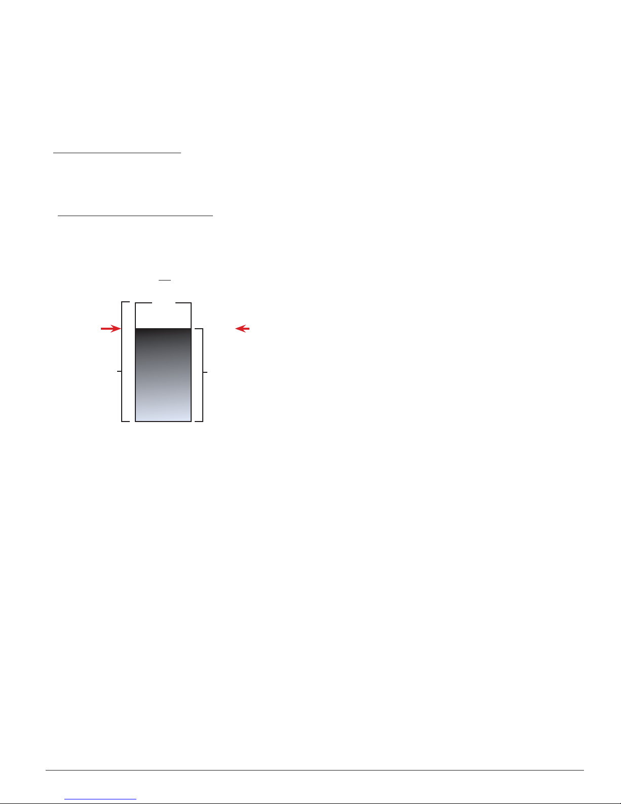
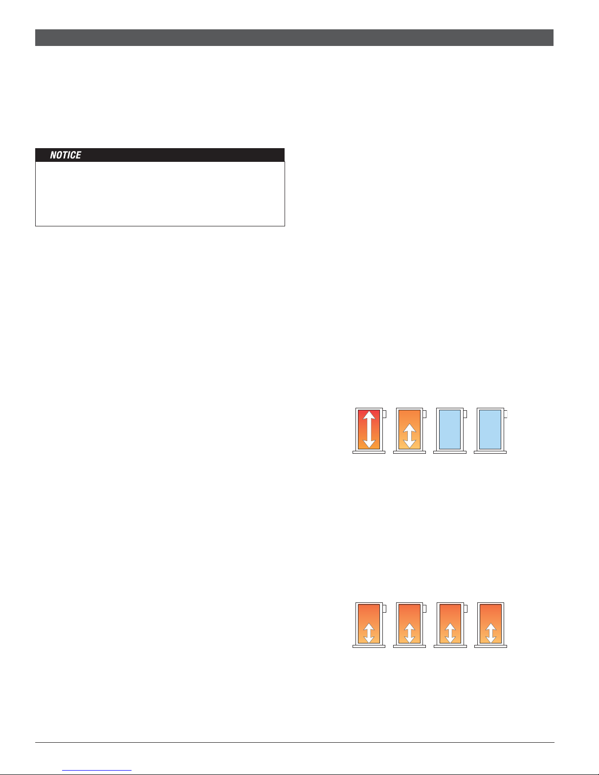
Boiler Minimum
-----------------------------------------
The Boil MIN is the lowest temperature that the control is allowed
to use as a boiler target temperature. During mild conditions, if
the control calculates a boiler target temperature that is below
the boiler minimum setting, the boiler target temperature is
adjusted to at least the boiler minimum setting. MIN is displayed
in the status field while viewing the boiler supply or target &
when the boiler target is boiler minimum & the boiler supply
is less than boiler minimum plus 5°F (2.5°C). Set the Boiler
Minimum setting to the boiler manufacturer’s recommended
temperature.
Requirements
: The Boil MIN is only applicable when at least
one of the boilers is configured for non-condensing.
Boil MIN + 5°F (2.5°C)
Boiler Dierential
e
e
r
B
B
o
o
i
i
l
l
W
W
MIN segment on
Boiler Maximum
a
a
e
e
T
T
t
t
e
e
r
r
----------------------------------------
r
u
u
t
t
a
a
r
r
e
e
p
p
m
m
The Boil MAX is the highest temperature that the control is
allowed to use as a boiler target temperature. MAX is displayed
in the status field viewing the boiler supply or target & when the
boiler target is boiler maximum & the boiler supply is greater
than boiler maximum minus 5°F (2.5°C). Set the boiler maximum
setting below the boiler operator or aquastat temperature.
B
B
o
o
i
i
l
l
W
W
MAX
segme nt
on
Boiler Differential
a
a
e
e
T
T
t
t
r
r
e
e
---------------------------------------
r
r
e
e
p
p
m
m
segme nt
u
u
t
t
a
a
MAX
r
r
on
e
e
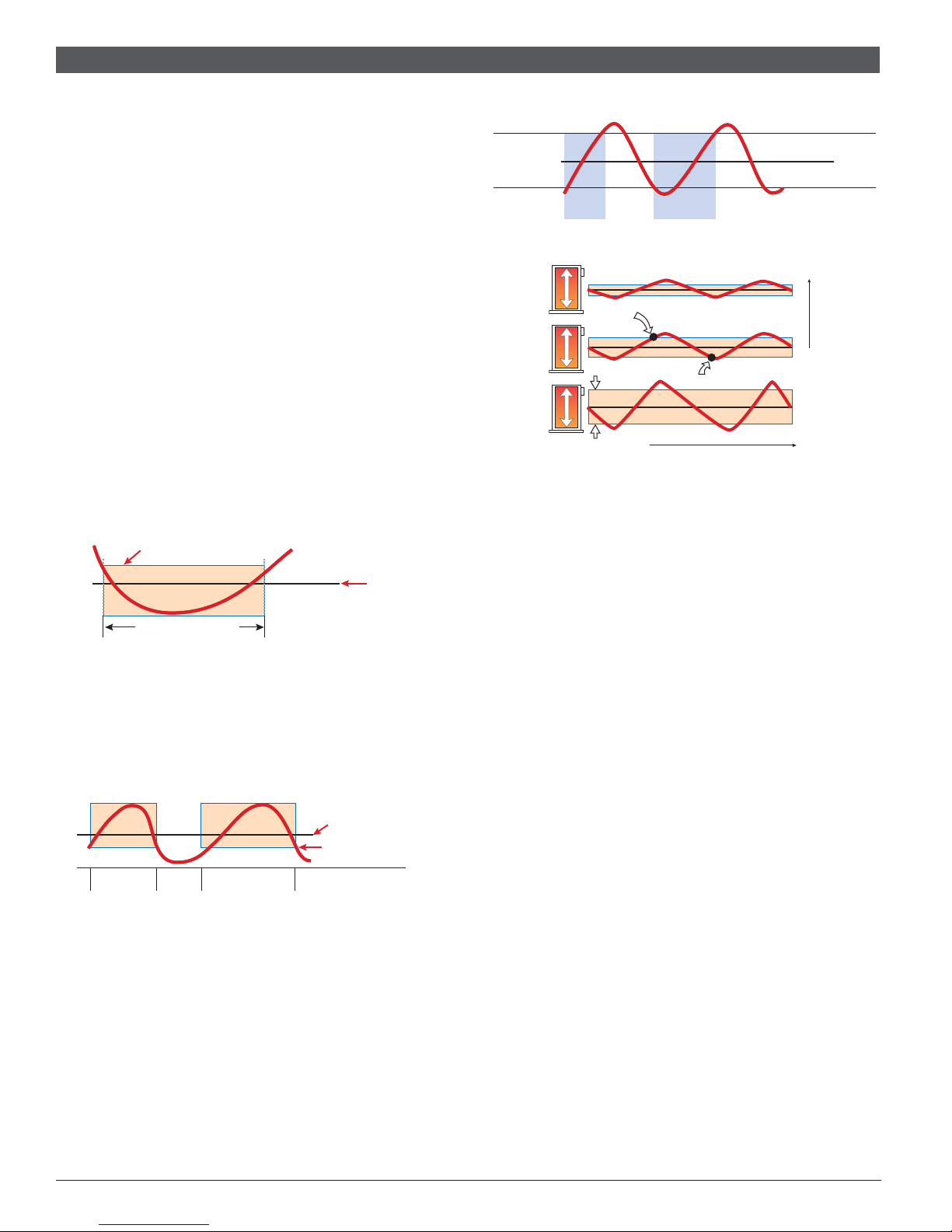
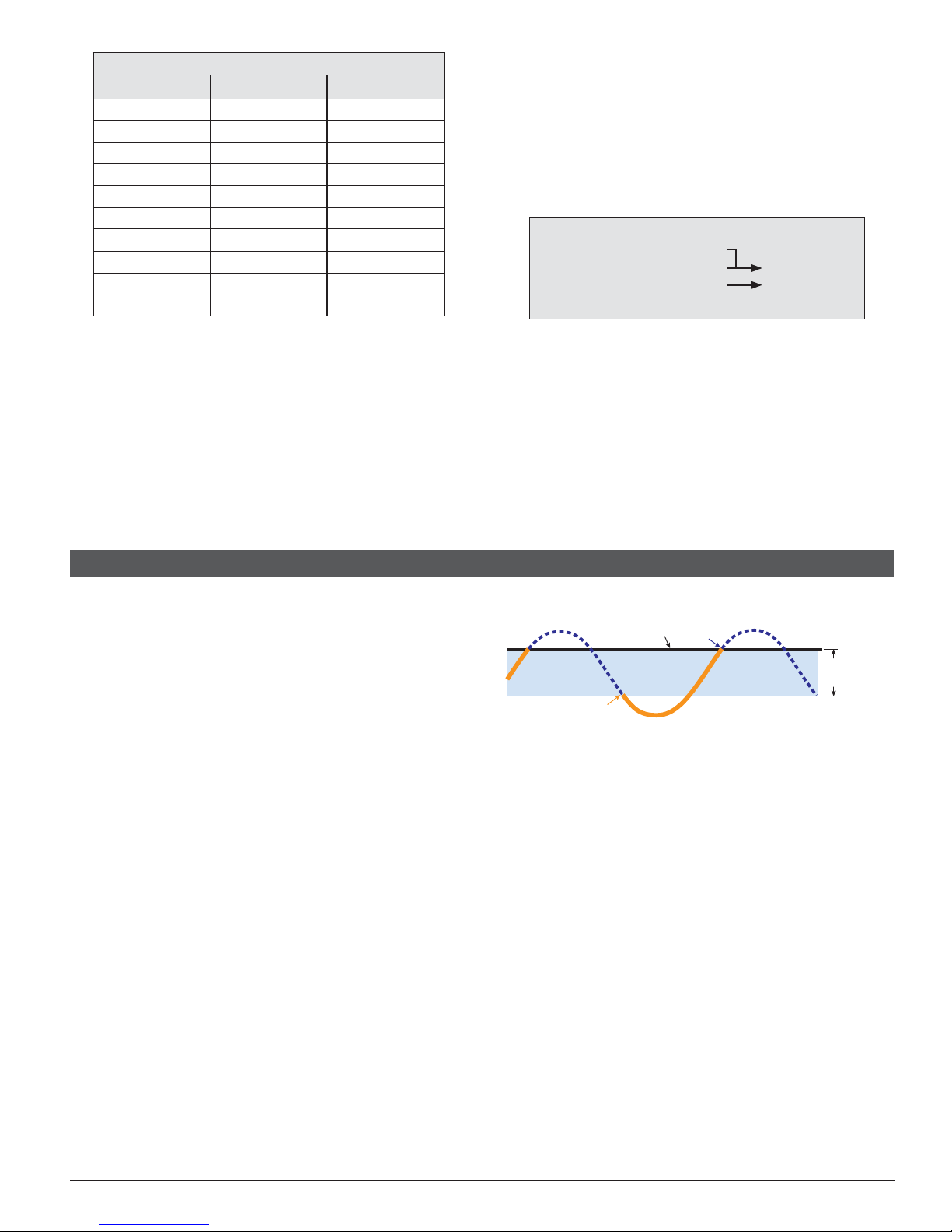
Both on/off (single stage & two stage) & modulating boilers are
operated with a differential. In some cases, a modulating boiler
must be operated with a differential at low fire. This indicates
the load is smaller than the minimum modulation of the boiler.
For modulating boilers, the differential no longer applies once
operating the boiler above low fire.
The differential operates by turning on the boiler when the
boiler supply water temperature is 1/2 of the differential below
the boiler target temperature. As the boiler supply water
temperature reaches 1/2 of the differential above the boiler
target temperature, the boiler is shut off.
Heatronic 4000
Boil MIN
Boil MAX
Boil MAX – 5°F (2.5°
Boiler Dierential
Manual Differential
Di erential = 10°F (6°C)
165°F (74°C)
160°F (71°C)
155°F (68°C)
Boiler
On
Boiler
On
Target + 1/2 Di e
Target – 1/2 Di e
Automatic Differential
Off
Exercising
Differential
Time
----------------------------------------------
On
The control will exercise all pumps for 10 seconds every three
days of inactivity to prevent seizure. To enable exercising, switch
the Exercise / Off DIP to the Exercise position.
Boost
---------------------------------------------------
When the control changes from the UnOccupied mode to the
Occupied mode, it enters into a boosting mode. In this mode,
the supply water temperature to the system is raised above its
normal values for a period of time to provide a faster recovery
from the setback temperature of the building. The maximum
length of the boost is selected using the BOOST setting in
the Setup menu.
Typical settings for the boost function vary between 30 minutes
& two hours for buildings that have a fast responding heating
system. For buildings that have a slow responding heating
system, a setting between four hours & eight hours is typical.
After a boost time is selected, the setback timer must be
adjusted to come out of setback some time in advance of the
desired occupied time. This time in advance is normally the
same as the BOOST setting.
If the building is not up to temperature at the correct time, the
BOOST setting should be lengthened & the setback timer should
be adjusted accordingly. If the building is up to temperature before
the required time, the BOOST setting should be shortened &
the setback timer should be adjusted accordingly. If the system
is operating near its design conditions or if the supply water
temperature is being limited by settings made in the control,
the time required to bring the building up to temperature may
be longer than expected.
6 of 60
BTC461503101C | 6720810369 (2018/03)
Targe
Heating Load

Flow Monitoring
----------------------------------------
-----------------------------------------
----------------------------------------
--------------------------------------
------------------------------------
----------------
------------------------------------------
The control has the capability to monitor flow through the connection of a 4-20 mA style analog flow sensor. Use the Flow Sensor
setting in the Setup menu to enable flow monitoring. The Flow
Rate 4 mA and Flow Rate 20 mA settings are then used to set
the minimum and maximum flow rates for the specific flow sensor
being used. Flow is measured in either gallons per minute (gpm)
or meters cubed per hour (m3/h). The units are adjustable through
the FLOW UNIT setting in the Toolbox menu.
In addition to flow monitoring, the flow sensor can also be
used to prove primary pump flow. Refer to the Pump Operation
section of this brochure for additional details.
Flow Rate 4 mA
The Flow Rate 4 mA is applicable for flow monitoring and is
based on the flow sensor being used. This setting sets the flow
rate at 4 mA.
Flow Rate 20 mA
The Flow Rate 20 mA is applicable for flow monitoring and is
based on the flow sensor being used. This setting sets the flow
rate at 20 mA.
Energy Monitoring
The control has the capability to monitor Energy. The control
requires the boiler supply, boiler return sensor & the flow sensor
in order to calculate & display energy in either Therms (THRM)
or Gigajoules (GJ). The units are adjustable through the TEMP
UNIT setting in the Toolbox menu.
Pressure Monitoring
The control has the capability to monitor system pressure
through the connection of a specific style of Vdc pressure
transducer.
to enable pressure monitoring.
psi or kPa. The units are adjustable through the PRESSURE
UNIT setting in the Toolbox menu.
Flue Temperature Monitoring & Limiting
The control has the capability to measure & limit the common
flue temperature. The FLUE MAX setting defines the operation
of the common flue sensor. If the common flue temperature
exceeds the FLUE MAX, the boiler plant is shut down. The boiler
plan will not be allowed to operate until the vent temperature
drops 10°F (6°C) below the FLUE MAX. If OFF is selected,
the common flue temperature is only monitored.
----------------------------------------
-----------------------------------------
----------------------------------------
--------------------------------------
------------------------------------
Use the Pressure Sensor setting in the Setup menu
Pressure is measured in either
----------------
Alert Dry Relay
The control has an Alert Dry relay that closes whenever a
control or sensor error is detected, or when a warning or limiting
condition is detected. When the alert dry contact closes, refer
to the Error Messages section of this brochure to determine
the cause of the alert & how to clear the error.
Boiler Alert
If no temperature increase is detected at the boiler supply sensor
within this delay period, the Alert relay will close & the control
will display the NO HEAT error message. To clear the error,
press the CLEAR button while viewing the error message.
------------------------------------------
BTC461503101C | 6720810369 (2018/03)
7 of 60
Heatronic 4000
Boiler Plant Operation
----------------------------------------
-------------------------------
---------------------------------------------
--------------------------------------
------------------------------------
The Heatronic 4000 is able to operate up to four boilers to
maintain a boiler target temperature. Proportional, Integral &
Derivative (PID) logic is used in order to satisfy the boiler target
temperature for all plant configurations with the exception of
Dedicated Domestic Hot Water (DDHW). Proportional (P) logic
is used for DDHW. For proper operation of the boilers, the
Heatronic 4000 must be the only control that determines
when a boiler is to fire.
The boiler operator, or aquastat, remains in the burner circuit
& acts as a secondary upper limit on the boiler temperature.
The boiler aquastat temperature setting must be adjusted
above the Heatronic 4000’s boiler maximum setting in order
to prevent short cycling of the burner.
Boiler Operation
Single Stage On⁄Off Boiler
Once a boiler is required to operate, the control turns on the
Stage 1 relay. Once the control turns on the Stage 1 relay, it will
display the “Boiler” icon & “100%” under the respective boiler
output status in the display.
Two Stage On⁄Off Boiler
Once a boiler is required to operate, the control turns on the
Stage 1 relay. Once the Fire Delay time plus the Stage Delay
time has expired, the control can turn on the Stage 2 relay if it
is required. Once the control turns on the Stage 1 relay, it will
display the “Boiler” icon & “50%” under the respective boiler
output status in the display. Once the control turns on the Stage
2 relay, it will display “100%”.
Modulating Boiler
Once a boiler is required to operate, the control outputs an
analog signal corresponding to the Start Modulation setting
& then turns on the Stage 1 relay. Once the Fire Delay time
has expired, the modulating output is adjusted to the Minimum
Modulation setting. The control then holds the modulating output
at the Minimum Modulation until the Minimum Modulation Delay
time has elapsed. The control can then adjust the modulating
output from the Minimum Modulation as required. Once the
control turns on the Stage 1 relay, it will display the “Boiler”
under the respective boiler output status in the display. The
current firing rate is also displayed in the boiler output field.
EMS Boiler
Once a boiler is required to operate, the control outputs an
appropriate analog signal corresponding to the boiler target
temperature & then turns on the Stage 1 relay. Once the control
turns on the Stage 1 relay, it will display the “Boiler” under the
respective boiler output status in the display. The target water
temperature is also displayed in the boiler output field.
Boiler Target Temperature
The Boil TARG temperature is determined by the application
mode & the type of call received. The control displays the
temperature that it is currently trying to maintain at the boiler
supply sensor in the View menu. If the control does not presently
have a requirement for heat, it does not show a boiler target
temperature. Instead, “---” is displayed in the LCD.
----------------------------------------
-------------------------------
Stage Delay
The STG DELAY is the minimum time delay between the firing
of each boiler or boiler stage. After this delay has expired the
control can fire the next boiler or boiler stage if it is required. This
setting can be adjusted manually or set to an automatic setting.
When the automatic setting is used, the control determines the
best stage delay based on the operation of the system.
Modulation Mode
When using multiple modulating boilers, a selection must be
made regarding the sequencing of the boilers. Two modulation
mode settings are provided considering condensing & noncondensing boiler groups.
Modulation Mode is not available when the Application Mode
is configured for Dedicated Domestic Hot Water (DDHW).
•
MOD COND (Modulation Mode - Modulating, Condensing
Boiler Group)
This setting is applicable for a group at least two modulating,
condensing boilers.
•
MOD NC (Modulation Mode - Modulating, Non-Condensing
Boiler Group)
This setting is applicable for a group of at least two modulating,
non-condensing boilers.
Sequential Modulation SEQ
With Sequential Modulation, the control will turn on the fewest
boilers possible to meet the load. The control will bring a
boiler from its Minimum Modulation setting up to its Maximum
Modulation setting before bringing on another boiler. When
another boiler is turned on, the previous boiler will keep its
output at full fire.
Parallel Modulation PAR
With Parallel Modulation, the control will turn on the most
boilers possible to meet the load. The control will bring on the
first boiler at Minimum Modulation and does not increase its
modulation. If more boiler output is required, the second boiler
will turn on at Minimum Modulation and does not increase its
modulation. Additional boilers are turned on at their Minimum
Modulation setting until all boilers are on. If still more boiler
output is required, all boilers are modulated up in parallel until
they reach their Maximum Modulation settings.
Staging Mode Setup
When using multiple two-stage boilers, a selection must be
made regarding the staging order of the boilers. Two staging
modes are provided considering condensing & non-condensing
boiler groups.
---------------------------------------------
--------------------------------------
100% 60% Off Off
40% 40% 40% 40%
------------------------------------
Heatronic 4000
8 of 60
BTC461503101C | 6720810369 (2018/03)

•
-----------------------------------
-----------------------------
----------------------------------------------
-----------------------------------------------
-----------
STG COND (Staging Mode - Two-Stage, Condensing Boiler
Group)
This setting is applicable for a group of at least two, two-stage
condensing boilers.
•
STG NC (Staging Mode - Two-Stage Non-Condensing
Boiler Group)
This setting is applicable for a group of at least two, two-stage
non-condensing boilers.
Lo⁄ Hi
If the Lo/Hi staging option is selected the control stages in
sequence all of the stages in a single boiler. Once all of the
stages are turned on, the control then stages in sequence all
of the stages of the next boiler in the rotation sequence.
Lo⁄ Lo
If the Lo/Lo staging option is selected, the control stages all of the
Lo stage outputs in all of the boilers first. Once all of the boilers
are operating on their Lo stages, the control then operates the
second stage in each boiler in the same order.
Boiler Group Rotation
The control has two rotation settings including one for the
condensing boiler group & another for the non-condensing
boiler group.
• ROT COND (Rotation - Condensing Boiler Group)
This setting is applicable for a group of at least two, two-stage
condensing boilers.
• ROT NC (Rotation - Non-Condensing Boiler Group)
This setting is applicable for a group of at least two, two-stage
non-condensing boilers.
The Rotate feature changes the firing order of the boilers
whenever one boiler accumulates 48 hours more run time than
any other boiler. Rotation will be forced if any boiler accumulates
60 hours more run time. After each rotation, the boiler with the
least running hours is the first to fire & the boiler with the most
running hours is the last to fire. This function ensures that all of
the boilers receive equal amounts of use. When the Rotation
setting is set to Off, the firing sequence always begins with
lowest boiler to the highest boiler.
1 2
720 hours
To reset the rotation sequence, clear the Burner Run Time in
the Monitor (#) Menu.
Boiler Run Time Monitoring
The running time of each boiler is logged in its respective Monitor
(#) menu. To reset the running time, select the appropriate
BURNER item in the Monitor (#) menu & select CLEAR until
“0” is displayed.
Fixed Lead
When the boiler plant includes only one boiler group, either a
condensing or a non-condensing group, a selection must be
made regarding operation of the lead boiler.
ON
In some applications, it may be desirable to have the first boiler
fire first at all times while the firing sequence of the remaining boilers is changed using Equal Run Time Rotation. This
configuration is typical of installations where the boiler plant
----------------------------------------------
-----------------------------------
2 1
672 hours
672 hours
-----------------------------
720 hours
includes similar boilers but the first boiler is required to be
the first to fire in order to establish sufficient draft for venting.
With a fixed lead rotation, the lead boiler is always turned on
first & turned off first. The Fixed Lead is always applied to the
boiler 1 output.
OFF
The lead boiler is not fixed to operate first in the firing sequence.
It is included in the rotation sequence with the other boilers.
Fixed Last
When the boiler plant includes only one boiler group, either a
condensing or a non-condensing group, a selection must be
made regarding operation of the last boiler.
ON
In some applications, it may be desirable to have the last
boiler fire last at all times while the firing sequence of the
remaining boilers is changed using Equal Run Time Rotation.
This configuration is typical of installations where the boiler
plant includes higher efficient boilers & a single lesser efficient
boiler. The lesser efficient boiler is only desired to be operated
when all other boilers in the plant are on & the load cannot be
satisfied. With a fixed last rotation, the last boiler is the last to
turn on & the first to turn off. The Fixed Last is always applied
to the boiler 4 output.
OFF
The last boiler is not fixed to operate last in the firing sequence.
It is included in the rotation sequence with the other boilers.
Condensing & Non-Condensing Boiler Groups
Operating a boiler plant that contains both condensing (high
initial cost) & non-condensing (lower initial cost) boilers allows
the boiler plant to achieve nearly the same operating efficiencies as operating all condensing boilers but at a much lower
installed cost to the building owner. High system efficiency can
be achieved as long as the condensing boilers are the first to
operate in the firing sequence. During mild weather, the lead
condensing boilers operate at lower boiler temperatures &
achieve their peak boiler efficiencies while the non-condensing
boilers are rarely operated. During very cold weather, the boiler
target temperature is often above the boiler’s condensation
point & the condensing & non-condensing boilers operate
together at roughly the same efficiency level.
When a condensing boiler is operating, it is desirable to operate
the boilers without a boiler minimum temperature being applied
to the boiler target. This allows the condensing boiler to operate
at its maximum efficiency. When a non-condensing boiler is
operating, a boiler minimum temperature should be applied to the
boiler target to prevent damage to the non-condensing boiler’s
heat exchanger from sustained flue gas condensation.
The Heatronic 4000 supports operation of a condensing & a
non-condensing boiler group. A condensing boiler group is
created when at least one boiler is selected to be condensing
& a non-condensing boiler group is created when at least
one boiler is selected to be non-condensing. The condensing
boiler group is always sequenced on first, followed by the
non-condensing boiler group.
-----------------------------------------------
-----------
BTC461503101C | 6720810369 (2018/03)
9 of 60
Heatronic 4000
-----------------------------------
----------------------------
-------------------------------------------
Dual Fuel Boiler Operation
---------------------------------------------
The Heatronic 4000 supports the operation of dual fuel
boilers. Dual fuel boiler functionality is only available with
applicable Bosch / Buderus boiler models. The control allows
for up to two dual fuel boilers with selection capability for
Boiler 1 and Boiler 3.
If a dual fuel boiler is selected for boiler 1, the boiler 1 output
is used to control the gas burner and the boiler 2 output is
used to control the oil burner. Also, the boiler pump and,
if applicable, boiler outlet sensor, are to be connected to
boiler 1.
If a dual fuel boiler is selected for boiler 3, the boiler 3 output
is used to control the gas burner and the boiler 4 output is
used to control the oil burner. Also, the boiler pump and,
Outdoor Temperature Reset Operation
if applicable, boiler outlet sensor, are to be connected to
boiler 3.
Fuel Switch
---------------------------------------------
A fuel switch is required in order for the control to switch
burner operation from gas to oil.
Once the control registers
a fuel switch, it will display FL SW in the status field. A
fuel switch is provided by a dry contact or 24 V (ac) signal
applied across the fuel switch terminals 9 & 10. The device
that provides a fuel switch is typically a manual switch
located on the boiler which selects what burner (gas or oil)
becomes active.
If the fuel switch is not present, the gas burner is active and
the oil burner is inactive. If the fuel switch is present, the oil
burner is active and the gas burner is inactive.
Outdoor Temperature Reset is available by setting the
Application Mode in the Setup Menu to RSET.
In a heating system, the rate of heat supplied to the building
must equal the rate at which heat is lost. If the two rates are
not equal, the building will either cool off or over heat.
The rate of building heat loss depends mostly on the outdoor
temperature. Outdoor Reset allows a hot water heating
system to increase the water temperature, adding heat to the
building, as the outdoor temperature drops. The rate at which
the water temperature is changed as a function of outdoor
temperature is defined by the characterized heating curve.
Indirect Domestic Hot Water (IDHW) operation is available
during outdoor temperature reset operation.
Central Heat (CH) Call
-----------------------------------
A CH Call is required in order for the control to provide target
water temperature for the space heating system. Once the
control registers a CH Call, it will display the “Heat” icon
under the Calls in the display. A heat call can be provided
in two ways:
Contact Closure
A dry contact or 24 V (ac) signal is applied across the CH
Call terminals 5 & 6.
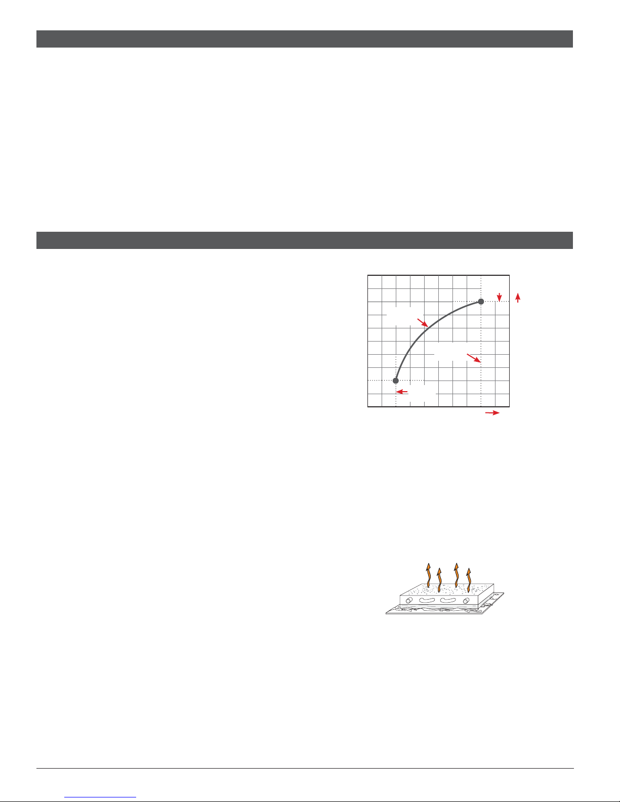
Characterized Heating Curve
----------------------------
A characterized heating curve determines the amount the
target water temperature is raised for every 1° drop in outdoor
air temperature.
The characterized heating curve takes into account the
type of terminal unit that the system is using. Since different
types of heating terminal units transfer heat to a space using
different proportions of radiation, convection & conduction,
the supply water temperature must be controlled differently.
The control uses the terminal unit setting to vary the supply
water temperature to suit the terminal unit being used. This
improves the control of the air temperature in the building.
Boiler Characterized Heating Curve
Boiler
Design
Terminal
Unit
Outdoor
Design
Boiler
Terminal Unit
Indoor
Decreasing Outdoor Temperatures
-------------------------------------------
Increasing Water Temperatures
Select the appropriate terminal unit in the Setup Menu. This
will change the shape of the characterized heating curve
to better match the heat transfer properties of that specific
terminal unit.
Hydronic Radiant Floor HRF
A heavy or high mass, hydronic radiant floor system. This type
of a hydronic radiant floor is embedded in either a thick concrete
or gypsum pour. This heating system has a large thermal mass
& is slow acting.
Heatronic 4000
10 of 60
BTC461503101C | 6720810369 (2018/03)
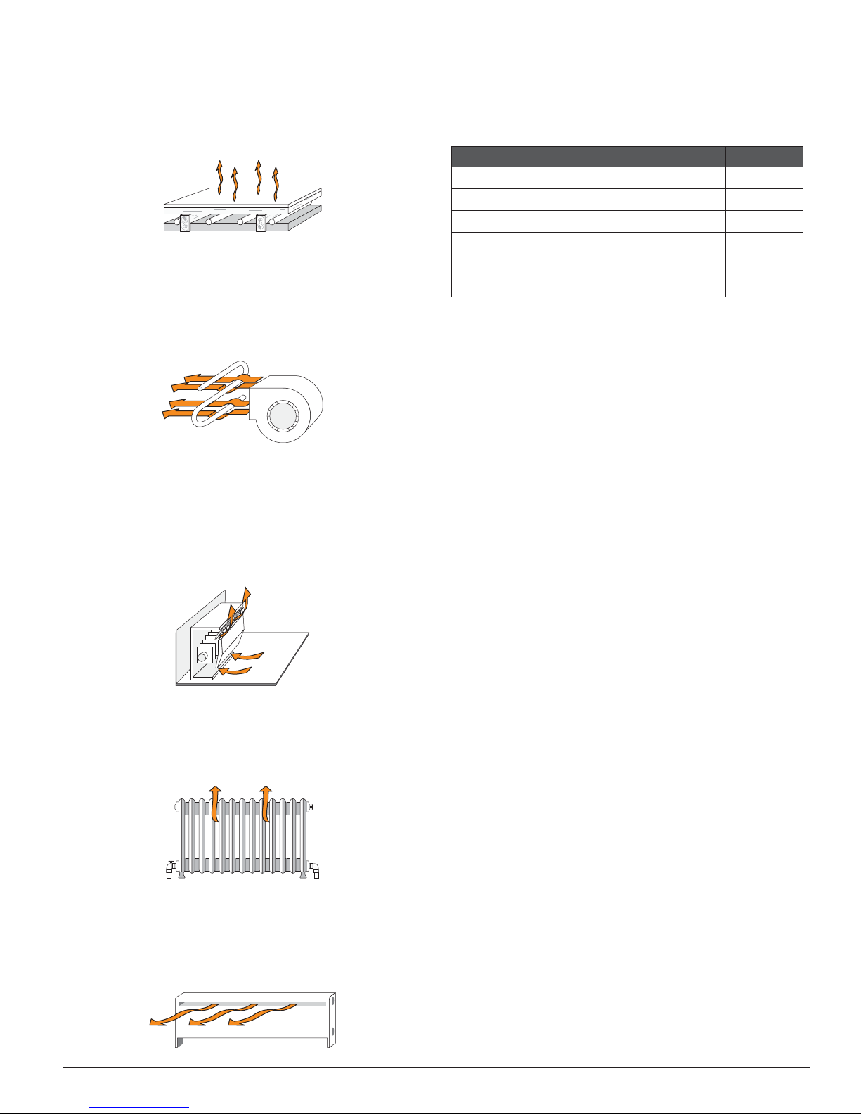
Hydronic Radiant Floor HRF
---------------------------------------------------
----------------------------------------
--------------------------------------------
-------------------------------------------
---------------------
A light or low mass, hydronic radiant floor system. Most
commonly, this type of radiant heating system is attached to
the bottom of a wood sub floor, suspended in the joist space,
or sandwiched between the subfloor & the surface. This type
of radiant system has a relatively low thermal mass & responds
faster than a high mass system.
Fancoil COIL
A fancoil terminal unit or air handling unit (AHU) consisting of
a hydronic heating coil & either a fan or blower. Air is forced
across the coil at a constant velocity by the fan or blower & is
then delivered into the building space.
Fin–tube Convector CONV
A convector terminal unit is made up of a heating element
with fins on it. This type of terminal unit relies on the natural
convection of air across the heating element to deliver heated air
into the space. The amount of natural convection is dependant
on the supply water temperature to the heating element & the
room air temperature.
Radiator RAD
A radiator terminal unit has a large heated surface that is
exposed to the room. A radiator provides heat to the room
through radiant heat transfer & natural convection.
Baseboard BASE
A baseboard terminal unit is similar to a radiator, but has a low
profile & is installed at the base of the wall. The proportion of
heat transferred by radiation from a baseboard is greater than
that from a fin-tube convector.
Boiler Terminal Unit Defaults
When a terminal unit is selected for boiler zones, the control
loads default values for the boiler design, boiler maximum
supply, & boiler minimum supply temperatures. The factory
defaults can be changed to better match the installed system.
Locate the Terminal Unit setting in the Setup menu.
Terminal Unit Boil DSGN Boil MAX *Boil MIN
High Mass Radiant
Low Mass Radiant
Fancoil
Fin-Tube Convector
Radiator
Baseboard
Requirements
set to non-condensing. If all available boilers are set to condensing, Boil MIN is not available & is hard-coded to OFF.
Room
The Room setting is the desired room air temperature, according
to the outdoor reset heating curve. The Room setting parallel
shifts the heating curve up or down to change the target water
temperature. Adjust the Room setting to increase or decrease
the amount of heat available to the building. Once the heating
curve has been set up properly, the Room setting is the only
setting that needs to be adjusted. The default Room setting
is 70°F (21°C), & it can be adjusted for both the occupied &
unoccupied periods.
: Boil MIN is only available if at least one boiler is
---------------------------------------------------
Outdoor Design
The outdoor design temperature is typically the coldest outdoor
air temperature of the year. This temperature is used when
doing the heat loss calculations for the building & is used to
size the heating system equipment. If a cold outdoor design
temperature is selected, the supply water temperature rises
gradually as the outdoor temperature drops. If a warm outdoor
design temperature is selected, the supply water temperature
rises rapidly as the outdoor temperature drops.
Boiler Indoor
The boiler indoor design temperature is the indoor temperature
the heating designer chose while calculating the heat loss for
the boiler water heated zones. This temperature is typically
70°F (21.0°C). This setting establishes the beginning of the
boiler characterized heating curve.
Boiler Design
The boiler design supply temperature is the boiler water
temperature required to heat the zones at the outdoor design
temperature, or on the typical coldest day of the year.
(Default automatically changes based on terminal unit
setting)
--------------------------------------------
-------------------------------------------
Warm Weather Shut Down (WWSD)
Warm Weather Shut Down disables the heating system when the
outdoor air temperature rises above this programmable setting.
When the control enters into WWSD, WWSD is indicated in
the status field. WWSD is only available when the Application
Mode is set to RSET.
While in WWSD, the control will still operate to provide
Indirect Domestic Hot Water or Setpoint operation.
120°F (49°C) 140°F (60°C) 140°F (60°C)
140°F (60°C) 160°F (71°C) 140°F (60°C)
190°F (88°C) 210°F (99°C) 140°F (60°C)
180°F (82°C) 200°F (93°C) 140°F (60°C)
160°F (71°C) 180°F (82°C) 140°F (60°C)
150°F (76°C) 170°F (77°C) 140°F (60°C)
----------------------------------------
---------------------
BTC461503101C | 6720810369 (2018/03)
11 of 60
Heatronic 4000

-----------------------------------
---------------
Setpoint Operation
------------------------------------------------
----------------------------------------------
If the Application Mode is configured for Setpoint (SETP), the
control provides heat for the setpoint load.
Indirect Domestic Hot Water (IDHW) operation is available
during setpoint operation.
Central Heat (CH) Call
A CH Call is required in order for the control to provide heat to
a setpoint load, such as a spa, pool or snowmelt load. Once
the control registers a CH Call, it will display the “Heat” icon
under the Calls in the display. A CH Call can be provided in
two ways:
Contact Closure
A dry contact or 24 V (ac) signal is applied across the CH Call
terminals 9 & 10.
Boiler Target Temperature During a Setpoint Call
When a CH Call is present, a boiler target is determined.
•
When using a Contact Closure, the boiler target is set to the
SETP Setpoint setting.
-----------------------------------
---------------
Energy Management System (EMS) Operation
The control can accept an external DC signal from an Energy
Management System (EMS). The control converts the DC
signal into the appropriate boiler target temperature for the
space heating system.
EMS is available by setting the APP MODE in the Setup Menu
to EMS.
Indirect Domestic Hot Water (IDHW) is available during
EMS operation.
Heat Call
A Heat Call is required in order for the control to provide a
target water temperature for the space heating system. Once
the control registers a Heat Call, it will display the “Heat” icon
under the Calls in the display.
A Heat Call is provided by:
Input Signal
An external signal is generated by applying a voltage between
0 V (dc) & 10 V (dc) across the EMS (+) In & Com (-) terminals
(16 & 19). Voltages that exceed 10 V (dc) will still be considered
a 10 V (dc) signal.
If the EMS signal goes below the minimum voltage, the “Heat”
icon under the Calls in the display is turned off. The boiler target
temperature is displayed as “– – –” to indicate that there is no
longer a call for heating.
External Central Heat (CH) Call terminals are not
operational.
EMS Signal
The control can accept either a 0-10 V (dc) signal or a 2-10 V
(dc) signal. The EMS SGNL setting must be set to the proper
setting based on the signal that is being sent to the control.
V dc or mA
When the 0-10 V (dc) signal is selected, an input voltage of 1 V
(dc) corresponds to a boiler target temperature of 50°F (10°C).
An input voltage of 10 V (dc) corresponds to a boiler target
temperature of 210°F (99°C). As the voltage varies between 1
V (dc) & 10 V (dc) the boiler target temperature varies linearly
between 50°F (10°C) & 210°F (99°C).
------------------------------------------------
----------------------------------------------
•
When using a tekmarNet® Setpoint Control, the boiler target
is set to the devices Exchange Supply setting.
If there are multiple devices calling for heat, the boiler target
is set to the highest temperature requirement.
Setpoint During UnOccupied
When using a Contact Closure, a second SETP Setpoint setting
is available for the Unoccupied periods.
DIP Switch must be set to Setback to view UnOccupied
items.
Setpoint operation is not provided during the Away
Scene.
If a voltage below 0.5 V (dc) is received the boiler target
temperature is displayed as “– – –” indicating that there is no
longer a call for heating.
A 0 - 20 mA signal can be converted to a 0 - 10 V (dc) signal
by installing a 500 resistor between the EMS (+) In & Com
(-) terminals (16 & 19).
V dc or mA
When the 2 - 10 V (dc) signal is selected, an input voltage of 2 V
(dc) corresponds to a boiler target temperature of 50°F (10°C).
An input voltage of 10 V (dc) corresponds to a boiler target
temperature of 210°F (99°C). As the voltage varies between 2
V (dc) & 10 V (dc) the boiler target temperature varies linearly
between 50°F (10°C) & 210°F (99°C). If a voltage below 1.5
V (dc) is received the boiler target temperature is displayed as
“– – –” indicating that there is no longer a call for heating.
A 4 - 20 mA signal can be converted to a 2 - 10 V (dc) signal
by installing a 500 resistor between the EMS (+) In & Com
(-) terminals (16 & 19).
CONVERSION TABLE 0 - 10
0 - 20 mA* 0 - 10 V (dc) Boiler Target
0 0 – – – (OFF)
2 1 50°F (10°C)
4 2 68°F (20°C)
6 3 86°F (30°C)
8 4 103°F (39°C)
10 5 121°F (49°C)
12 6 139°F (59°C)
14 7 157°F (69°C)
16 8 174°F (79°C)
18 9 192°F (89°C)
20 10 210°F (99°C)
*Requires 500 Resistor in Parallel
Heatronic 4000
12 of 60
BTC461503101C | 6720810369 (2018/03)
CONVERSION TABLE 2 - 10
-----------------------------------------------
----------------------------------------
l
--------------
------------------------------
4 - 20 mA* 2 - 10 V (dc) Boiler Target
0 0 – – – (OFF)
4 2 50°F (10°C)
6 3 70°F (21°C)
8 4 90°F (32°C)
10 5 110°F (43°C)
12 6 130°F (54°C)
14 7 150°F (66°C)
16 8 170°F (77°C)
18 9 190°F (88°C)
20 10 210°F (99°C)
*Requires 500 Resistor in Parallel
EMS Offset
For external input operation, the boiler target (determined
from the external input signal) may be fine tuned. The EMS
OFFST setting is used to provide the fine tuning. The setting
may be adjusted ±10°F (±5.5°C). When set to 0°F (0.0°C), if
the temperature determined from the external signal is 140°F
(60.0°C), the boiler target will be 140°F (60.0°C). When set
to +5°F (+3.0°C) & with the same external signal represents
140°F (60.0°C), the boiler target will be 145°F (63.0°C).
Example
Range = 0 - 10 V (dc)
Input = 7 V (dc) 157°F (69°C)
Offset = +5°F (3°C) + 5°F (3°C)
Boiler Target = 162°F (72°C)
The minimum & maximum settings also apply for external input
operation. For example, if a boiler minimum of 140°F (60.0°C) is
set & the external signal received represents 80°F (27.0°C), the
boiler target will be 140°F (60.0°C). MIN will also be displayed
in the status field to indicate that a limiting condition is in effect.
This also applies for the MAX limit.
Indirect Domestic Hot Water (DHW) Operation
IDHW operation is applicable during the following application
modes: outdoor temperature reset, fixed setpoint & EMS.
DHW Call
A DHW Call is required in order for the control to provide heat
to an indirect DHW tank. Once the control registers a DHW
Call, it will display the “DHW” icon under Calls in the display.
A DHW Call can be provided in three ways:
DHW Tank Aquastat
If a DHW Tank Aquastat (mechanical switch) is used to apply
a DHW Call, the tank is heated to the aquastat temperature
setting. A dry contact or 24 V (ac) signal is applied across the
DHW Tank Call terminals 7 & 8.
Requirements
DHW Sensor
A DHW Tank Sensor provides superior temperature control of
the tank compared to an aquastat. The control can register a
DHW Call when a DHW Sensor is wired to terminals 21 & 22.
Once the DHW Sensor temperature drops 1/2 of the IDHW
Differential setting below the IDHW Setpoint, the control
registers a DHW Call.
Requirements
cannot be an external IDHW Call when using a DHW sensor.
DHW Differential
Due to large differences between the heating load & the DHW
load, a separate DHW differential should be used whenever a
DHW Call is present. This will improve staging & boiler cycling.
When using a DHW Sensor, a DHW Call is registered when the
temperature at the DHW sensor drops the IDHW DIFF setting
below the IDHW Setpoint setting. The DHW Call is satisfied
-----------------------------------------------
: IDHW Sensor must be set to Off.
: The IDHW Sensor must be set to On. There
----------------------------------------
once the temperature at the DHW Sensor rises to the IDHW
Setpoint setting.
DHW Target
ON
Boiler Target Temperature during a DHW Call
OFF
IDHW
Differentia
--------------
When a DHW Call is present, a boiler target is determined.
•
When using a DHW Tank Aquastat, the boiler target is set
to the IDHW Exchange setting.
When using a DHW Tank Sensor, the boiler target is fixed
•
at the IDHW Setpoint setting plus 40°F (22.0°C).
When using a tekmarNet® Setpoint Control, the boiler target
•
is set to the devices Exchange Supply setting.
If there are multiple devices calling for heat, the boiler target
is set to the highest temperature requirement.
IDHW During UnOccupied
------------------------------
When using a DHW Tank Aquastat, a second IDHW Exchange
setting is available for the UnOccupied or Sleep period.
When using a DHW Sensor, a second IDHW Setpoint setting
is available for the UnOccupied or Sleep period.
DIP Switch must be set to Setback to view UnOccupied items.
During the Away Scene, DHW Calls are ignored.
BTC461503101C | 6720810369 (2018/03)
13 of 60
Heatronic 4000
IDHW Mode
--------------------------------------------
------------------------------------------
--------------------------------------------------
-------------------------------------------
--------------------------------------------
The control has a IDHW MODE setting that selects whether
or not indirect DHW operation is active.
OFF
IDHW operation is inactive. All DHW Calls are ignored. If this
mode is selected while DHW operation is underway, all DHW
operation ceases.
ON
IDHW operation is active. All DHW Calls are responded to.
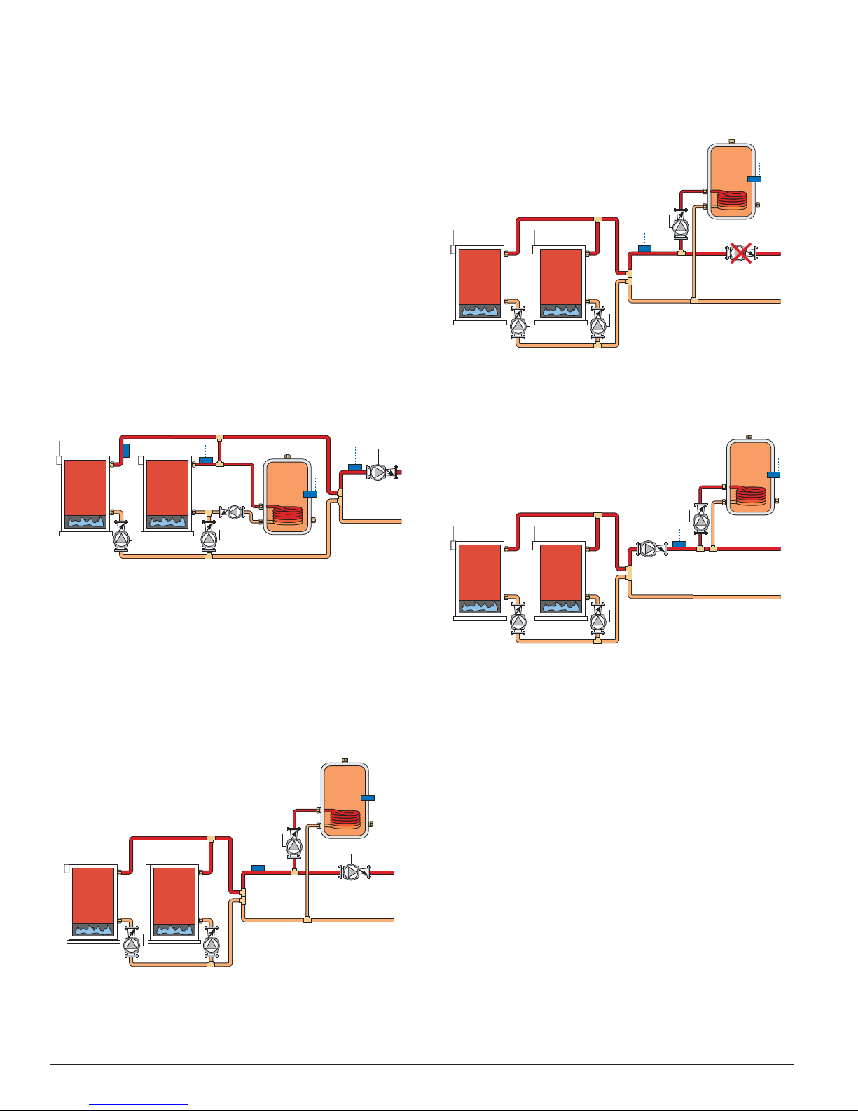
IDHW Location
------------------------------------------
The control has a IDHW Location setting that selects where
the indirect DHW tank is located in the system. This setting
determines the operating sensor & affects pump operation.
NEAR
The indirect DHW tank is piped in parallel within the near boiler
piping of boiler 4. When a valid DHW Call is present, the IDHW
Pump relay turns on & boiler pump 4 turns off. The control uses
the boiler 4 outlet sensor as the operating sensor in order to
measure the boiler supply temperature supplied to the indirect
DHW tank. There are two boiler target temperatures. One for
the space heating system (Boil TARG) & one for the indirect
DHW system (IDHW TARG).
OFF
The primary pump does not turn on during indirect DHW operation. This would be typical of an indirect DHW tank piped in
parallel in the boiler system loop. It is assumed that the DHW
pump will provide adequate flow through the indirect DHW
heat exchanger & the boiler system loop.
DHW
Pump
ON
Primary
Pump OFF
ON
The primary pump turns on during indirect DHW operation.
This would be typical of an indirect DHW tank piped in
primary/secondary in the boiler system loop.
Near Boiler
• All boilers are used for space heating requirements.
Boiler 4 is used for indirect DHW when there is a DHW
•
Call.
The dedicated indirect DHW boiler is always boiler 4, even
•
if there are less than four boilers.
• If boiler 4 is disabled & NEAR is selected for the IDHW Location,
the dedicated indirect DHW boiler 4 will not operate.
PRIM
The indirect DHW tank is piped in the boiler system loop. When
a valid DHW Call is present, the IDHW Pump relay turns on.
Piped off
boiler
system loop
DHW
Pump
ON
Primary
Pump ON
IDHW Priority
-------------------------------------------
The control has a IDHW Priority setting that selects whether or
not priority of indirect DHW is required over the space heating
system. Indirect DHW priority stops or limits the delivery of
heat to the space heating system while the indirect DHW tank
calls for heat. This allows for quick recovery of the indirect
DHW tank.
OFF
IDHW priority is not provided. The primary pump can operate
when a Heat Call is present. Heating zones are unaffected by
indirect DHW operation.
ON
IDHW priority is provided. The primary pump shuts off for a
period of time to provide priority.
Primary Pump During IDHW
--------------------------------------------------
The control has a Primary Pump during IDHW setting that
selects whether or not the primary pump is required during
indirect DHW operation.
Heatronic 4000
14 of 60
BTC461503101C | 6720810369 (2018/03)

Priority Override
----------------------------------------
-------------------------------
---------------------------------------
-------------------------------------
--------------------
--------------------------------
Priority override applies when IDHW Priority is set to ON &
prevents the building from cooling off too much or the possibility
of a potential freeze up during IDHW priority.
When set to auto, the priority time is calculated based on outdoor
temperature. At or below the design outdoor temperature, 15
minutes is allowed for IDHW priority. At or above the design
indoor temperature, 2 hours is allowed for IDHW priority. The
time allowed for IDHW priority varies linearly between the
above two points. There is a manual setting also available in
the Setup menu.
The priority timer does not start timing until priority is selected
& both a DHW Call & a Heat Call exist together. Once the
allowed time for priority has elapsed, the control overrides the
DHW priority & resumes space heating.
Requirements
mode is set to RSET.
----------------------------------------
: Auto is only available when the application
Automatic Priority Override
2 hours
15 mins
Indoor Design
Temperature
Conditional IDHW Priority
If the boiler supply temperature is maintained at or above the
required temperature during IDHW operation, this indicates that
the boilers have enough capacity for IDHW & possibly heating
as well. As long as the boiler supply temperature is maintained
near the target, IDHW & heating occurs simultaneously.
IDHW Post Purge
After the DHW Call is removed, the control performs a purge.
The control shuts off the boilers & continues to operate the
IDHW Pump & the primary pump if applicable. This purges the
residual heat from the boilers into the DHW tank. The control
continues this purge until one of the following occurs:
1. A Het Cll is detected.
2. The biler supply drps 20°F (11.0°C) belw the DHW
trget temperture.
3. The DHW tnk temperture rises bve the DHW setpint
plus 1/2 DHW Differentil.
4. Tw minutes elpse.
IDHW Mixing Purge
After IDHW operation, the boiler is extremely hot. At the same
time, the heating zones may have cooled off considerably after
being off for a period of time. When restarting the heating
system after a DHW Call with priority, the control shuts off the
boiler & continues to operate the IDHW pump while the primary
pump is turned on. This allows some of the DHW return water
to mix with the cool return water from the zones & temper the
boiler return water.
---------------------------------------
-------------------------------------
Outdoor Design
Temperature
-------------------------------
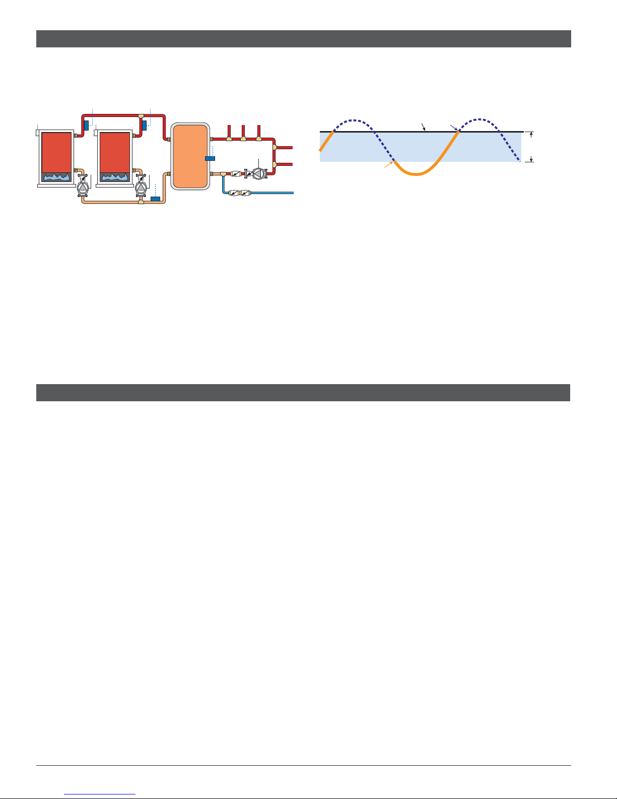
IDHW with Low Temperature Boilers
If DHW heating is to be incorporated into a low temperature
system such as a radiant floor heating system, a mixing device
is often installed to isolate the high DHW supply temperature
from the lower system temperature. If a mixing device is not
installed, high temperature water could be supplied to the
low temperature system while trying to satisfy the DHW Call.
This may result in damage to the low temperature heating
system.
The control is capable of providing IDHW heating in such a
system while minimizing the chance that the temperature in the
heating system exceeds the design supply water temperature.
In order to do this, the following must be true:
• All available boilers are set to condensing.
• IDHW Location set to PRIM.
• Primary Pump DURING IDHW set to OFF.
• IDHW Priority set to ON.
On a DHW Call, the control provides IDHW priority by turning
off the primary pump for a period of time. The length of time is
based on the outdoor air temperature, or selectable time, as
described in the IDHW Priority Override section. However, if
the DHW Call is not satisfied within the allotted time, the boiler
shuts off & the heat of the boiler is purged into the DHW tank. A
IDHW mixing purge occurs in order to reduce the boiler water
temperature & once the boiler supply temperature is sufficiently
reduced, the IDHW Pump contact shuts off. The primary pump
is allowed to turn on for a period of time to prevent the building
from cooling off. After a period of heating, & if the DHW Call is
still present, the control shuts off the primary pump & provides
heat to the DHW tank once again.
IDHW Boil COUNT IDHW
Selects the number of boilers to be used for IDHW operation.
This applies when only there is a requirement for IDHW. All
available boilers are allowed to operate if there is both a
requirement for space heating & IDHW.
--------------------------------
--------------------
BTC461503101C | 6720810369 (2018/03)
15 of 60
Heatronic 4000
-----------------------------------------------
--------------------------------------
l
------------
-----------------------------
Dedicated Domestic Hot Water (DDHW) Operation
----------------------------------------------
-----------------------------------------------
-----------
The control can operate to provide heat for a Dedicated
Domestic Hot Water (DDHW) system.
DDHW heating is available by setting the Application Mode in
the Setup Menu to DDHW.
DHW Call
A DHW Call is required in order for the control to provide heat
to a dedicated DHW tank. Once the control registers a DHW
Call, it will display the “DHW” icon under Calls in the display.
This can be done by:
DHW Sensor
The control can register a DHW Call when a DHW Sensor is
wired to terminals 21 & 22. Once the DHW Sensor temperature
drops 1/2 of the DDHW Differential setting below the DDHW
Setpoint, the control registers a DHW Call.
-----------------------------------------------
DDHW Differential
A DHW Call is registered when the temperature at the DHW
sensor drops the DDHW DIFF setting below the DDHW Setpoint
setting. The DHW Call is satisfied once the temperature at the
DHW Sensor rises to the DDHW Setpoint setting.
Boiler Target Temperature During a DDHW Call
When a DHW Call is present, a boiler target is determined. The
boiler target is set to the DDHW Setpoint setting.
DDHW During UnOccupied
A second DDHW Setpoint setting is available for the
UnOccupied periods.
DIP Switch must be set to Setback to view UnOccupied
items.
During the Away Scene, DHW Calls are ignored.
--------------------------------------
DHW Target
ON
OFF
-----------------------------
IDHW
Differentia
------------
Building Automation System (BAS)
The control can communicate with a Building Automation System
(BAS) to provide remote monitoring & adjustment capability.
BAS Mode
There are two modes of BAS communication that define the
interaction between the BAS & the control. The level of interaction is determined by the Application Mode setting.
Refer to the Heatronic 4000 BAS Manual for more information
including a listing of the read / write parameters.
Monitor
Monitor mode is available when the Application Mode is set
to either Outdoor Temperature Reset, Setpoint, Dedicated
Domestic Hot Water (DDHW) or Energy Management System
(EMS). The BAS Monitor item in the BAS Menu must be set to
ON to enable Monitor mode.
With Monitor mode, the control allows for viewing & adjustment
capability of select items within the various menus.
Tem pe ratu re
Temperature mode is available when the Application Mode is
set to Building Automation System (BAS).
With Temperature mode, the control operates to maintain the
setpoint temperature provided over the BAS network. In order
for the control to be able to operate to maintain the BAS Setpoint
temperature, the BAS must also write a Heat Call command
over the BAS network.
Whenever a BAS Heat Call command is received, the Heat
segment is turned under the Calls in the status field of the
display.
----------------------------------------------
If primary pump operation is desired, the BAS must write a
BAS Primary Pump command over the BAS network.
If indirect DHW pump operation is desired, the BAS must write
a BAS IDHW Pump command over the BAS network.
BAS Type
The control supports Modbus® & BACnet® IP communications. Selection is made through BAS TYPE item in the BAS
menu.
Network Configuration Settings in BAS Menu
Refer to the BAS menu section of this brochure for a listing of
all the BAS network configuration settings.
-----------------------------------------------
-----------
Heatronic 4000
16 of 60
BTC461503101C | 6720810369 (2018/03)
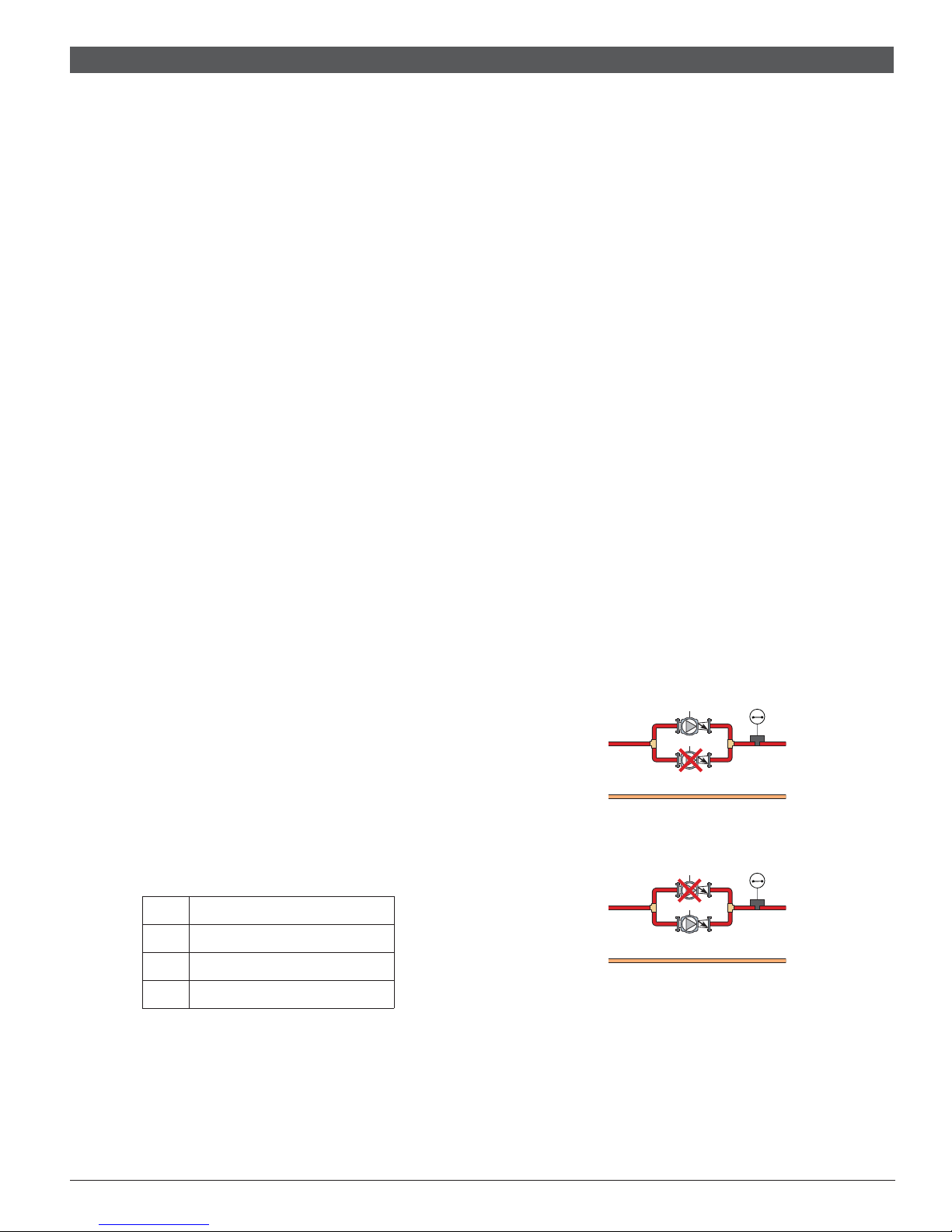
Pump Operation
--------------------------------
-------------------------------
-------------------------------------
----------------------------------------
Primary Pump Operation
The control includes two primary pump outputs with capability
for sequencing. There is pump enable setting for each primary
pump in the Setup menu. When both primary pumps are set
to Auto, primary pump sequencing is activated. Primary pump
1 & 2 are operated in stand-by mode when pump sequencing
is activated.
The running times of the primary pumps are logged in the
Monitor Menu. To reset these values back to zero, select
“Clear” while viewing this item.
Operation of the primary pump(s) is determined from the
Application Mode & the presence of an appropriate call.
Application Mode: Outdoor Temperature Reset RSET
• Heat Call from Contact Closure.
DHW Call & the Primary Pump during IDHW operation set
•
to ON.
Application Mode: Setpoint SETP
• Heat Call from Contact Closure.
DHW Call & the Primary Pump during IDHW operation set
•
to ON.
Application Mode: Energy Management System EMS
• Heat Call from Analog Input Signal.
DHW Call & the Primary Pump during IDHW operation set
•
to ON.
Application Mode: Building Automation System BAS
• BAS Primary Pump request.
Primary Pump Flow Proof
The control includes a flow proof in order to prove flow once
a primary pump has turned on. In order for boiler operation to
commence the proof must be present. A flow proof is required
at all times during pump operation.
Once a primary pump contact is turned on, a flow proof must
be present before the flow proof delay has expired.
The Flow Proof feature is enabled by setting the DIP switch to
the Prim Pump Flow Proof position.
A flow proof can be provided in two ways:
Contact Closure
A dry contact or 24 V (ac) signal is applied across the PrimPump
Flow Proof terminals 1 & 2.
A contact closure can come from a flow switch, pressure
differential switch, current sensing or power sensing device.
--------------------------------
-------------------------------
mA Analog Flow Sensor
A 4-20 mA analog flow sensor can be used to monitor & prove
primary flow. The Flow Sensor item in the Setup Menu must be
set to ON to enable the flow sensor to provide monitoring.
To enable the flow proof feature, the Flow Proof item in the Setup
Menu must be set to a flow percentage. The flow percentage
is the percentage of full flow (dependant on the flow model
selected) that must be achieved within the flow proof delay
time to prove flow. If the flow sensor is not required to prove
flow, the Flow Proof item must be set to OFF.
Stand-by Operation
The control only operates one primary pump at a time. A
flow proof device can be used to detect when stand-by pump
operation is required.
•
When an appropriate Call is registered, the lead pump is
activated, & the control waits for flow to be established within
the flow proof delay time.
If no flow is established, the lead pump is de-activated, the
•
lag pump is activated & the control waits again for the flow
to establish within the flow proof delay time.
If no flow is established with the lag pump, the control
•
will make a second attempt to prove flow with the pumps,
starting with the lead pump. If flow cannot be proved after
the second attempts, the control stops operation until the
error is cleared. Verify that the pumps & flow proof device
are working correctly before clearing the error.
If the lead pump establishes flow, & fails during operation,
•
the lag pump is activated.
If at any time, one or both pumps fail to prove flow, an error
•
message is displayed.
Normal Operation
Stand-by Pump Operation
-------------------------------------
ON
OFF
Fail ed
∆P Pressure Differential Switch
FS Flow Switch
KW Power Sensing Device
Amp Current Sensing Device
BTC461503101C | 6720810369 (2018/03)
ON
Flow Proof Delay
The control waits a period of time to receive a flow proof call
from the time the primary pump turns on. If the control does
not receive a flow proof call within that period of time, the
primary pump turns off & the stand-by primary pump (if active)
turns on. The control then waits that period of time again for
the stand-by primary pump to prove flow. If flow is not proven,
the stand-by pump turns off. The period of time is set through
the FLW PROOF item in the Setup menu & it is adjustable
between 10 seconds & 3 minutes.
17 of 60
----------------------------------------
Heatronic 4000

Flow Proof Demand Test
--------------------------------
---------------------------------
------------------------------------
----------------------------------
-------------
---------------------
The control includes a flow proof test in order to determine if the
flow device has failed. A flow proof failure is detected if a flow
proof is present after the pumps have been shut off for more
than four minutes. This can occur if the flow proof device sticks
in the on position even when flow has stopped in the system.
A flow proof call error will latch when this condition exists.
Primary Pump Rotation
The control rotates the pumps based on the primary pump
Rotate item in the Setup menu. Frequency of Rotation is based
on the running time of the pumps. Rotation is done when the
lead pump is off. If the lead pump runs continuously, the rotation
is delayed for up to 12 hours. If the pump runs continuously
& rotation is required, the control shuts off the lead pump & 1
second later the stand-by pump is turned on. This eliminates
overloading the pump electrical circuit. Upon turning on the
stand-by pump the flow proof call input is checked after the
flow proof call delay time.
Primary Pump Purge
After the last valid call is removed, the primary pump is operated
for an additional period of time. The purge period for the primary
pump is adjustable between 10 seconds & 20:00 minutes.
Boiler Pump Operation
The control includes relays to operate the boiler pumps.
Prepurge
The control includes a boiler pump pre-purge which operates
the respective boiler pump for a period of time before the boiler
is ignited in order to purge potential residual heat out of the
boiler. The pre-purge time is determined from the boiler mass
setting. As the boiler mass setting is increased, the boiler pump
pre-purge time is also increased. The pre-purge time is fixed
at 4 seconds whenever a DHW Tank Call is provided in order
to reduce boiler pick-up times.
Postpurge
The control includes a boiler pump post-purge feature that
operates the respective boiler pump for a period of time after
the boiler is turned off. This feature will purge heat out of the
boiler & aid in reducing “kettling”. The amount of time for the
boiler pump post purge is adjustable between 10 seconds &
20:00 minutes.
Pump Logic
The control includes a special pump logic feature for protection
against flue gas condensation due to cool water temperatures.
The pump logic feature considers a flow temperature condition applicable after turning on a boiler and a burner turn-off
condition applicable when turning off a boiler. The pump logic
feature is only applicable for Bosch / Buderus boiler models
that are non-condensing.
The control uses the boiler outlet sensor of the respective boiler
for the pump logic feature. If the boiler outlet sensor becomes
unavailable, the boiler will be locked out from operation.
For the flow temperature condition, a minimum temperature
of 122°F (50°C) must be reached within 10 minutes from the
time flame has been established within the boiler.
If the boiler outlet temperature reaches 122°F (50°C) within
10:00 minutes from the time flame has been established,
the boiler pump remains on and the burner is operated as
required to satisfy the Boiler Target temperature. If the boiler
outlet temperature then drops below 122°F (50°C), the boiler
--------------------------------
---------------------------------
------------------------------------
----------------------------------
pump is turned off until the boiler outlet temperature reaches
the 122°F (50°C).
If the boiler outlet temperature does not reach 122°F (50°C)
within 10:00 minutes from the time flame has been established,
the boiler pump turns off. The boiler pump then remains off until
°
the boiler outlet temperature reaches 122
For the burner turn-off condition, a minimum temperature of
129°F (54°C) is required in order for the burner to be turned
off. Also, for modulating boilers, the burner is adjusted to a
maximum of 60% rate prior to being turned off.
If the boiler outlet temperature of an applicable boiler is at
least 129°F (54°C) when it is required to be turned off, the
burner output is adjusted to 60% (for modulating burner). The
burner then turns off.
If the boiler outlet temperature of an applicable boiler is less
than 129°F (54°C) when it is required to be turned off, the
boiler pump is turned off and the output is adjusted to 60% (for
modulating burner) until the boiler outlet temperature reaches
129°F (54°C).
Indirect DHW (IDHW) Tank Pump Operation
The control includes a relay to operate an indirect DHW
tank pump.
Operation of the IDHW tank pump is determined by the
Application Mode & the presence of an appropriate call.
Application Mode: Outdoor Temperature Reset
Setpoint Energy Management System
• DHW Call from Contact Closure.
• DHW Call from DHW Sensor.
Application Mode: Building Automation System
• BAS DHW Pump Call.
DHW Recirculation Pump Operation
The control has the capability to operate a DHW Recirculation
Pump when the control is configured for either Indirect
Domestic Hot Water (IDHW) or Dedicated Domestic Hot
Water (DDHW). IDHW is available when the application
mode is set to either outdoor temperature reset, setpoint or
EMS. DDHW is available when the applicable mode is set
to DDHW. The Aux Relay setting in the Setup Menu must
be set to DHWR to enable the DHW recirculation pump.
The DHW recirculation pump operates continuously during the
Occupied period. If setback is enabled, the pump operates
when heat is required during the Unoccupied period.
F (50°C).
-------------
---------------------
Heatronic 4000
18 of 60
BTC461503101C | 6720810369 (2018/03)
 Loading...