

Bosch HDZBS301 Installation Manual

INSTALLATION MANUAL
For Dual Fuel SIR Low Backguard
Models/
Modèles/
Modelos:
MANUEL D’INSTALLATION
Pour Dossert Bas de Cuisinière Encastrée
Bi-Combustible
MANUAL DE INSTALACIÓN
Placa antisalpicaduras inferior de la estufa
deslizante de dos combustibles
HDZBS301
For Ranges/
Pour Cuisinières/
Estufas/
HDI8054UC
HDIP054UC


Table of Contents
Questions?
1-800-944-2904
www.bosch-home.com/us
We look forward to hearing from you!
This Bosch Appliance is made by
BSH Home Appliances Corporation
1901 Main Street, Suite 600
Irvine, CA 92614
Safety Definitions . . . . . . . . . . . . . . . 1
Appliance Handling Safety . . . . . . . . . . . . . . 2
Low Backguard Installation
(HDZBS301) . . . . . . . . . . . . . . . . . . . . 3
Procedure for a Dual Fuel Slide-In-Range
with louver cover . . . . . . . . . . . . . . . . . . . . . 3
Tools Needed . . . . . . . . . . . . . . . . . . . . . . . . 3
Preparation . . . . . . . . . . . . . . . . . . . . . . . . . . 3
Procedure. . . . . . . . . . . . . . . . . . . . . . . . . . . . 3
Procedure for a Dual Fuel Slide-In-Range
without louver cover . . . . . . . . . . . . . . . . . . 5
Tools Needed . . . . . . . . . . . . . . . . . . . . . . . . 5
Preparation . . . . . . . . . . . . . . . . . . . . . . . . . . 5
Procedure . . . . . . . . . . . . . . . . . . . . . . . . . . . 5


9 IMPORTANT SAFETY INSTRUCTIONS
9 WARNING:
If the information in this manual is not followed exactly, a
fire or explosion may result causing property dama ge ,
personal injury or death.
-- Do not store or use combustible materials,
gasoline or other flammable vapors and liquids
in the vicinity of this or any other appliance.
-- WHAT TO DO IF YOU SMELL GAS
• Do not try to light any appliance.
• Do not touch any electrical switch.
• Do not use any phone in your building.
• Immediately call your gas supplier from a
neighbor’s phone. Follow the gas supplier’s
instructions.
• If you cannot reach your gas supplier, call
the fire department.
-- Installation and service must be perf ormed by a
qualified installer, authorized service agency or
the gas supplier.
READ AND SAVE THESE INSTRUCTIONS
Safety Definitions
WARNING
9
This indicates that death or serious injuries may
occur as a result of non-observance of this warning.
CAUTION
9
This indicates that minor or moderate injuries may
occur as a result of non-observance of this warning.
NOTICE: This indicates that damage to the appliance or
property may occur as a result of non-compliance with this
advisory.
Note: This alerts you to important information and/or tips.
9001062516 Rev A English 1
9 IMPORTANT SAFETY INSTRUCTIONS
READ AND SAVE THESE INSTRUCTIONS
9 WARNING
If the information in this manual is not followed
exactly, property damage or personal injury may
result.
Read the instructions completely before attempting
one of these procedures.
Installation of a Low Backguard requires access to
the mounting screws on the back and sides of the
range. If electrical or gas connections prevent access
to the screws, contact a qualified technician before
proceeding.
Appliance Handling Safety
9 WARNING
TIP OVER HAZARD!
A child or adult can tip the
range over and be killed.
Verify that the anti-tip
bracket is securely installed.
Ensure the anti-tip bracket
is engaged whenever the
range is moved to a new
location.
Do not operate the range without the anti-tip bracket
in place. Failure to follow the instructions in this
manual can result in death or serious burns to
children and adults.
9 CAUTION
• The range is heavy and requires at least two
persons or proper equipment to move.
• Hidden surfaces may have sharp edges. Use
gloves and caution when reaching behind or
under appliance.
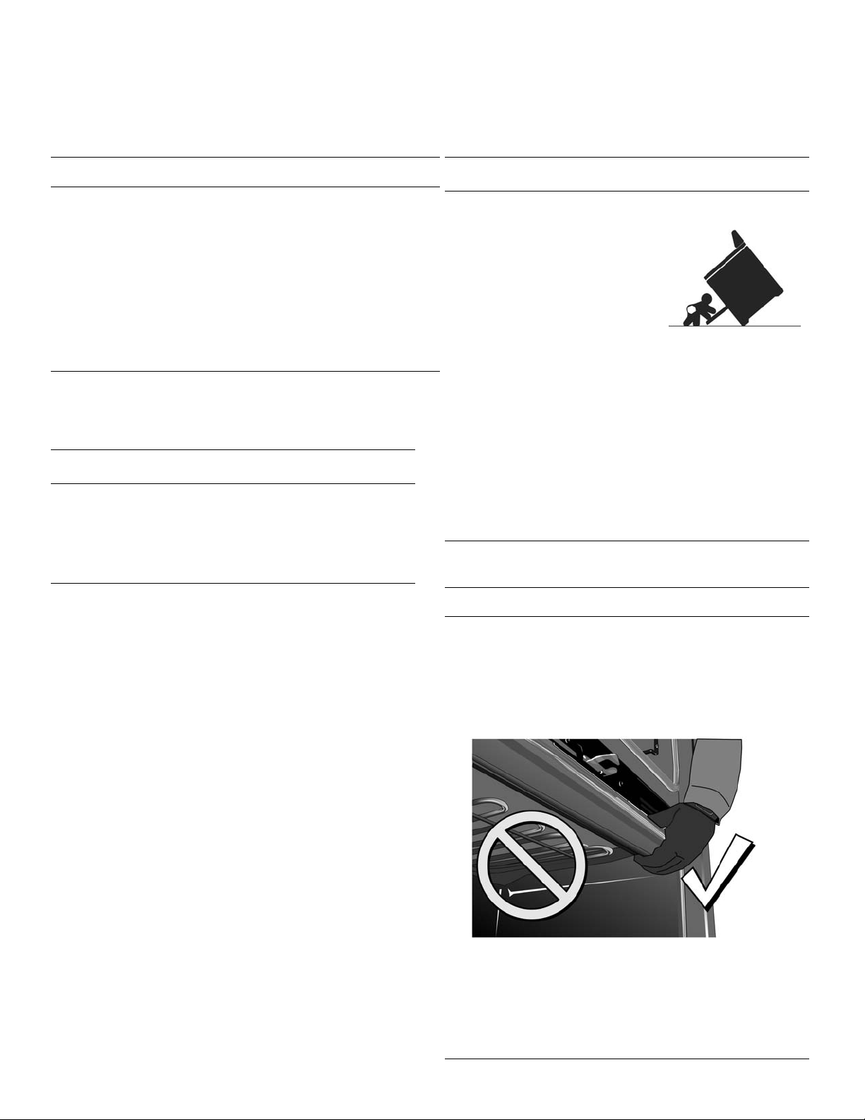
Do not move the range by the oven door handle. You may
wish to remove the oven door for easier handling. See the
Installation Manual for your range for more information.
Turn power OFF at the service pan el. Lock service panel to
prevent power from being turned ON acc ide n tally.
Refer to range data plate for more information. See the
Installation Manual for your range for the data plate
location.
Check for proper installation and use of the anti-tip
bracket. Carefully tip the range forward pulling from
the back to ensure that the anti-tip bracket engages
the range leg and prevents tip-over. Range should
not move more than 1” (25 mm).
NOTICE
Proper Handling Technique
To avoid risk of damage to the range oven door, do
not lift, push, or pull the range by holding the door
handle. Take care not to touch the oven heating
element also located at the top of the oven cavity,
just behind the ridged area.
Note: It is recommended to wear gloves and long
sleeves to protect hands and forearms from
abrasion and potential scratches during the sliding
process. It is also recommended to take off watches
and jewelry and to wear work shoes during
installation for foot protection.
.English 2 9001062516 Rev A
Low Backguard Installation (HDZBS301)
Notice:
There are two types of Dual Fuel Slide-In-Ranges; one with
a louver cover at the back of the range and one without the
louver cover. See the following procedures to determine
which model of range that you have and which procedure
to follow.
Procedure for a Dual Fuel
Slide-In-Range with louver
cover (see Figure 1)
Tools Needed
• Torx T20 screwdriver
•gloves
Preparation
9 IMPORTANT!
Can you slide the range out enough to have access to the
rear and side screws of the rear louver cover and trim?
• If you can slide the range out, continue with the
procedure.
• If you cannot slide the range out, contact a qualified
service technician to disconnect the gas or electrical
connections that prevent the range from being pulled
out before proceeding.
• Read the Tip Over W arning in the Safety sectio n of this
manual. Be aware of this hazard when the range has
been pulled out of the anti-tip bracket for this
installation.
Procedure
1. Confirm that the range is cool enough to be handled on
all surfaces.
2. Slide the range out enough to access the rear louver
cover mounting screws. See Figure 1: Rear louver
cover screw locations.
3. If your range does not have a louver cover (see
Figure 1), go to the procedure starting on p age 5.
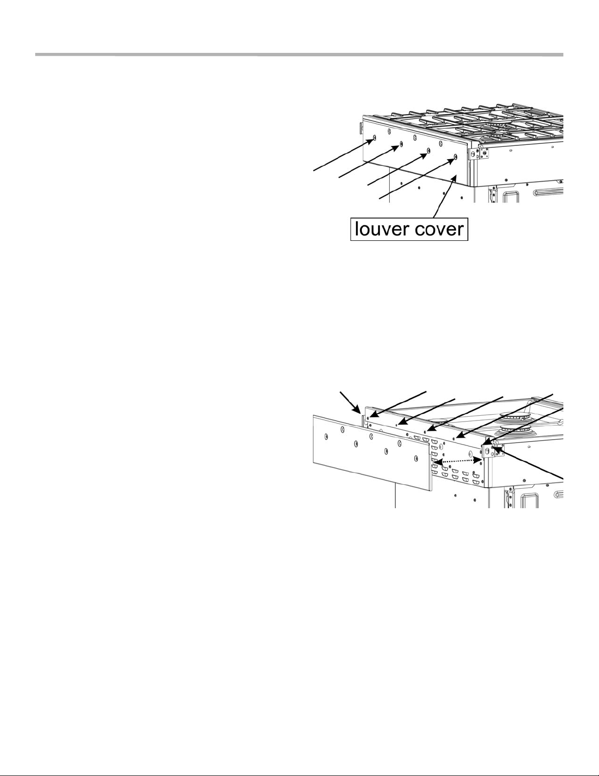
4. Remove the four screws holding the rear louver cover
(see Figure 1). Save these screws to reattach the
louver cover.
Figure 1: Rear louver cover screw locations
5. Lift the louver cover out of the slots holding it in place
(see Figure 2). Note the slot locations for later.
6. Remove the cooktop grates.
7. Remove the screws holding the trim (five screws on the
back and one screw on each end)(see Figured 2).
Save these screws for installation of the Low
Backguard.
Figure 2: Trim screw locations (louver cover removed)
8. Rotate the trim forward, slide slightly to the front, and
lift it off.
9001062516 Rev A English 3
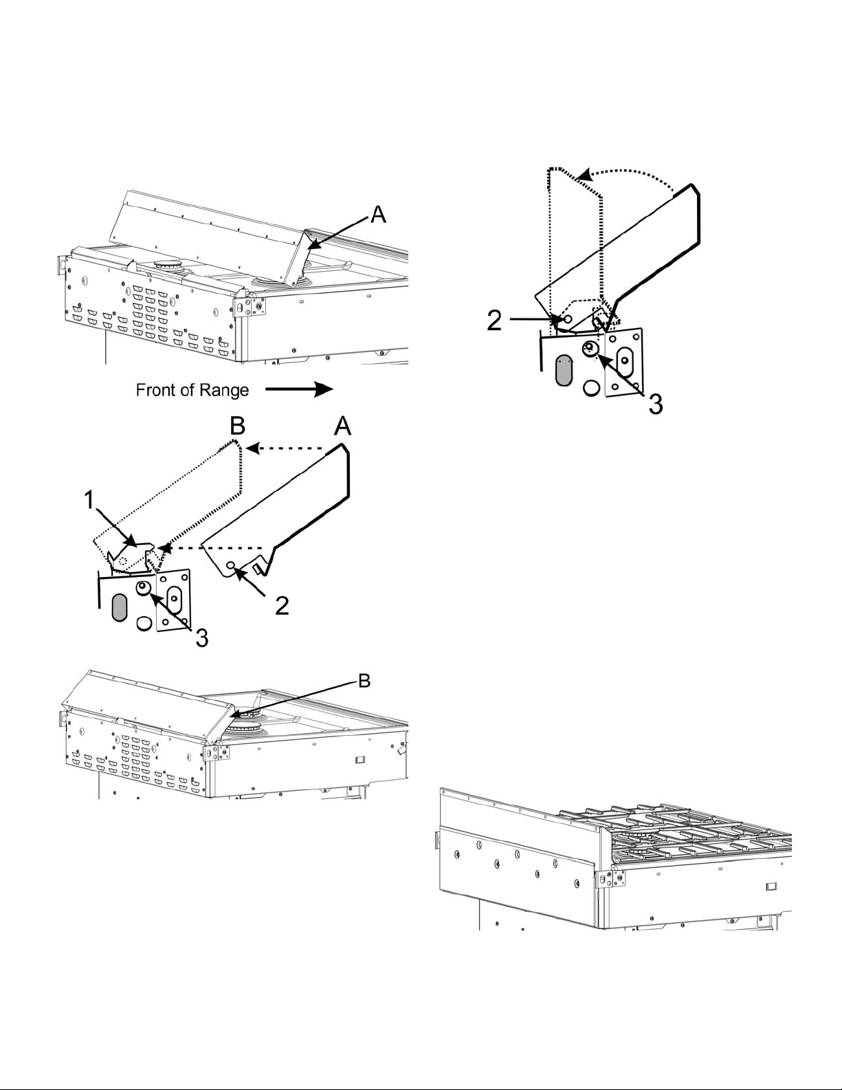
9. Place the Low Backguard in position A (See Figure 3)
and then move it to position B (engaging the alignment
device 1 inside the Low Backguard) (th e appearance of
the devices may not be exactly as shown).
10. Rotate the Low Backguard to a vertical position,
aligning hole 2 in the Low Backguard with hole 3 on
both sides of the range (see Figure 4).
Figure 4: Low Backguard placement 2
Figure 3: Low Backguard placement 1
1 1. Secure the Low Backguard with one screw at each end
(through holes 2 and 3) (lightly tighten).
12. Hold the Low Backguard in a vertical position while
installing and tightening the five screws in the back
(see Figure 2).
13. Finish tightening the screws at each end.
14. Place the rear louver cover into its slots and secure
with four screws (see Figures 1 and 2).
15. If necessary, have a qualified service technician
reattach the electrical or gas connections, while
performing the next step in the procedure.
16. Slide the range back into position, being sure to
engage the anti-tip bracket. See the Tip Over Hazard
Warning earlier in this instruction and also in the SlideIn Range Installation Manual.
17. Replace the cooktop grates.
Figure 5: Low Backguard in position
English 4 9001062516 Rev A
Procedure for a Dual Fuel
Slide-In-Range without louver
cover
Tools Needed
• Torx T20 screwdriver
•gloves
Preparation
9 IMPORTANT!
Can you slide the range out enough to have access to the
rear and side rear trim screws? See Figure 6.
• If you can slide the range out, continue with the
procedure,
• If you cannot slide the range out, contact a qualified
service technician to disconnect the gas or electrical
connections that prevent the range from being pulled
out before continuing with the procedure.
• Read the Tip Over W arning in the Safety Section of this
manual. Be aware of this when the range has been
pulled out of the anti-tip bracket for this installation.
Procedure
1. Confirm that the range is cool enough to be handled on
all surfaces.
2. Slide the range out enough to access the trim mounting
screws.
3. Remove the cooktop grates.
4. If the rear of the range does not look like the range in
Figure 6, go to the procedure on page 3.
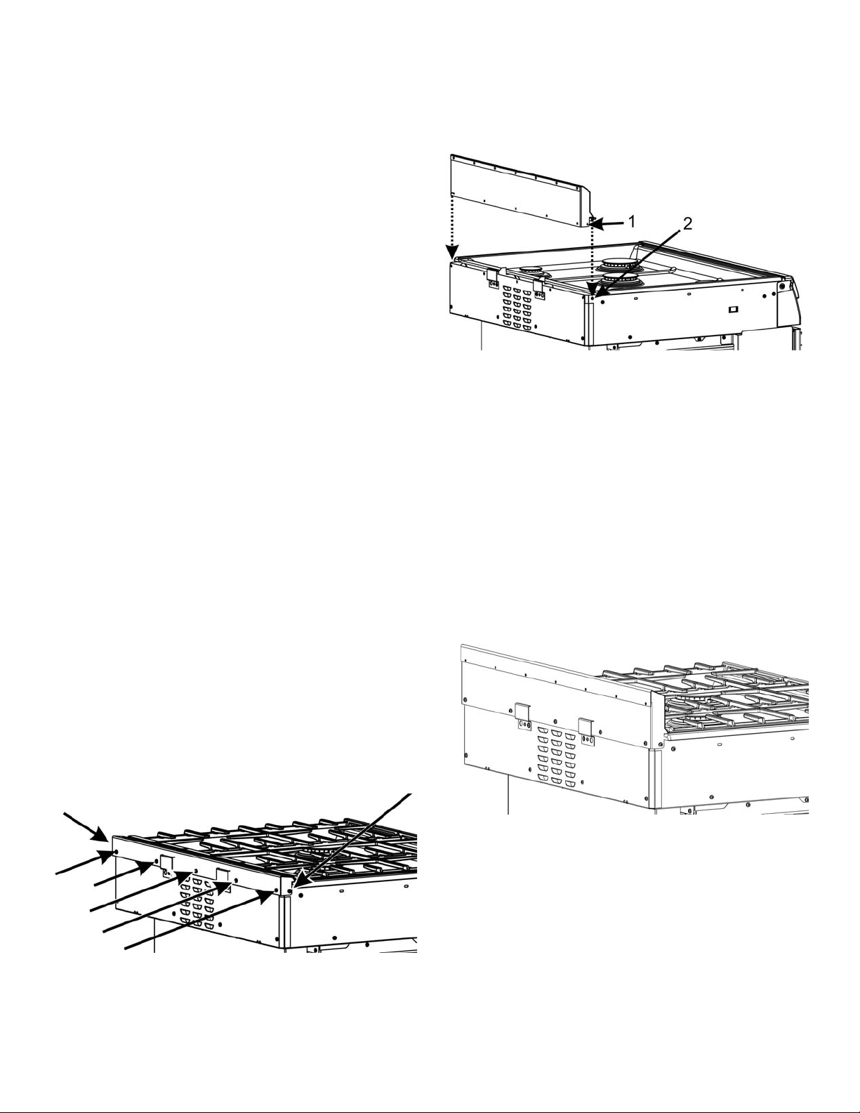
5. Remove the screws holding the trim (five screws on the
back and one screw on each end)(see Figure 6). Save
these screws for installing the Low Backguard.
7. Lower the Low Backguard into place, aligning the holes
at 1 with the holes at 2 on both sides of the range. See
Figure 7.
Figure 7: Low Backguard placement
8. Secure the Low Backguard with one screw at each end
and then hold the Low Backguard in a vertical position
while securing the 5 screws in the back (see Figure 6).
9. If necessary, have a qualified service technician
reattach the electrical or gas connections, while
performing the next step in the procedure.
10. Slide the range back into position, being sure to
engage the anti-tip bracket. See the Tip Over Hazard
Warning earlier in this instruction and also in the SlideIn Range Installation Manual
11. Replace the cooktop grates.
Figure 8: Low Backguard in position
Figure 6: Trim screw locations
6. Lift the trim off.
9001062516 Rev A English 5
 Loading...