

Bosch HBL8661UC, HBL8451UC, HBL8651UC, HBL8742UC, HBL8442UC Service Manual
...
S
ERVICE MANUAL
for
800 Series
Built-in Wall Ovens
HBL8442UC HBL8752UCC*
HBL8451UC HBL87M52UCC*
HBL8461UC HBL8742UCC*
HBL8642UC
HBL8651UC HBN8451UC
HBL8661UC HBN8651UC
This manual contains information that is necessary for
servicing the following Bosch electric built-in wall ovens:
HBL8442UC, HBL8451UC, HBL8461UC, HBL8642UC,
HBL8651UC, HBL8661UC, HBL8742UC
HBL8752UCC, HBL87M52UCC, HBL8742UCC
HBN8451UC, HBN8651UC
This manual is designed to be used by qualified service
personnel only. Due to the complexity and the risk of
high-voltage electrical shock, Bosch does not recommend
that customers service their own units.
This material is intended for the sole use of BSH
authorized persons and may contain confidential and
proprietary information. Any unauthorized review, use,
copying, disclosure, or distribution in any format is
prohibited.
*HBL8752UCC is the traditional wall oven component of
the HBL8752UC combination oven (set), which also
includes the HMC80252UC Speed microwave oven.
**HBL87M52UCC is the traditional wall oven component
of the HBL87M52UC combination oven (set), which also
includes the HMB50152UC Solo microwave oven.
**HBL8742UCC is the traditional wall oven component of
the HBL8742UC combination oven (set), which also
includes the HMC80242UC Speed microwave oven.

58300000202443_ARA_EN_C JANUARY 2018 Service Manual for Bosch 800 Series Built-in Wall Ovens
Page 2 of 43
Copyright by BSH Home Appliances Corporation 1901 Main St ▪ Suite 600 ▪ Irvine, CA 92614 800 944-2904
This material is intended for the sole use of BSH authorized persons and may contain confidential and proprietary information. Any unauthorized review, use, copying, disclosure, or distribution in any format is prohibited.
TABLE OF CONTENTS
1 Symbols Used in this Manual .................................................... 3
2 IMPORTANT SAFETY INFORMATION ....................................... 4
2.1 Safety Before Servicing the Appliance .................................. 4
3 General ........................................................................................ 6
3.1 Recap of Functional/Technical Changes ............................... 6
3.2 Models ................................................................................... 6
3.2.1 Combination Ovens (Sets) ............................................. 7
3.3 Rating Label .......................................................................... 7
3.4 Warranty ................................................................................ 8
4 Operation ..................................................................................... 9
4.1 Allowable Operating Range by Cooking Mode ...................... 9
4.2 Heating Elements .................................................................. 9
4.2.1 Elements Used by Cooking Mode ................................ 10
4.2.2 Element Duty Cycles .................................................... 10
4.2.3 Setting Temperature Offsets ........................................ 11
4.3 Self-clean ............................................................................ 12
4.4 Cooling Fan ......................................................................... 12
5 Component Accessibility ......................................................... 13
5.1 Serviceable from the Front .................................................. 13
5.2 Serviceable from the Side ................................................... 13
5.3 Serviceable from the Rear ................................................... 13
5.4 Serviceable from the Top .................................................... 13
5.4.1 Top Access: Non-combination Models ......................... 14
5.4.2 Top Access: Combination Models ................................ 14
6 Service and Repair ................................................................... 16
6.1 Doors ................................................................................... 16
6.1.1 Removing and Reinstalling the Door ............................ 16
6.1.2 Replacing Hinges ......................................................... 17
6.1.3 Replacing the 2-Pane Glass Pack ............................... 18
6.2 Door Latch/Motor Assembly ................................................ 19
6.2.1 Replacing the Latch/Motor Assembly ........................... 20
6.3 Oven High Temperature Cutout (HTC) ............................... 20
6.3.1 Resetting and Replacing the HTC ................................ 21
6.4 Control Panel ....................................................................... 22
6.4.1 Replacing the Front Panel Assembly ........................... 22
6.4.2 Replacing the Display Module ..................................... 23
6.5 Cavity Lights ....................................................................... 23
6.5.1 Replacing the Lamp ..................................................... 24
6.6 Convection Fan, Ring Element and Motor .......................... 24
6.6.1 Replacing the Convection Fan Blade .......................... 24
6.6.2 Replacing the Ring Element ........................................ 24
6.6.3 Replacing the Convection Fan Motor .......................... 25
6.7 Broil Element ...................................................................... 25
6.7.1 Replacing the Broil Element ........................................ 26
6.8 Bake Element ..................................................................... 26
6.8.1 Replacing the Bake Element ....................................... 26
6.9 Temperature Sensor ........................................................... 27
6.10 Control Module (Relay Board) and Daughter Board ........... 27
6.10.1 Replacing the Control Module or Daughter Board ....... 28
6.11 Cooling Fan ........................................................................ 28
6.11.1 Replacing the Cooling Fan .......................................... 28
6.12 Hinge Receivers ................................................................. 29
6.12.1 Replacing the Hinge Receivers ................................... 29
7 Troubleshooting ....................................................................... 31
7.1 Error Codes ........................................................................ 31
7.2 Service Mode ...................................................................... 36
7.2.1 Accessing Service Mode ............................................. 36
7.2.2 Setting the Option Code .............................................. 37
7.2.3 Displaying Error Memory ............................................. 37
7.2.4 Testing Relays ............................................................. 38
7.2.5 Testing Front Panel ..................................................... 38
7.3 Fault Trees .......................................................................... 39
7.5 Wiring Diagrams and Schematics ....................................... 42
7.5.1 Wire Color Key ............................................................ 42
7.5.2 Strip Diagrams ............................................................. 42
8 Additional References ............................................................. 43
8.1 QuickFinder ........................................................................ 43
8.2 Technical Support ............................................................... 43

58300000202443_ARA_EN_C JANUARY 2018 Service Manual for Bosch 800 Series Built-in Wall Ovens
Page 3 of 43
Copyright by BSH Home Appliances Corporation 1901 Main St ▪ Suite 600 ▪ Irvine, CA 92614 800 944-2904
This material is intended for the sole use of BSH authorized persons and may contain confidential and proprietary information. Any unauthorized review, use, copying, disclosure, or distribution in any format is prohibited.
1 SYMBOLS USED IN THIS MANUAL
WARNING – this symbol alerts you to dangers that may
result in bodily injury or death
CAUTION – this symbol alerts you to actions that may
result in damage to the product or property
NOTICE – this symbol alerts you to important
information and/or service tips.
VIDEO – related service video available for viewing on
QuickFinder
!
!
58300000202443_ARA_EN_C JANUARY 2018 Service Manual for Bosch 800 Series Built-in Wall Ovens
Page 4 of 43
Copyright by BSH Home Appliances Corporation 1901 Main St ▪ Suite 600 ▪ Irvine, CA 92614 800 944-2904
This material is intended for the sole use of BSH authorized persons and may contain confidential and proprietary information. Any unauthorized review, use, copying, disclosure, or distribution in any format is prohibited.
2 IMPORTANT SAFETY INFORMATION
Before starting to service an appliance, familiarize yourself with all
safety information and precautions included in this manual.
2.1 Safety Before Servicing the Appliance
WARNING
Before disassembly, removal, or installation of any
component…
Turn off electrical power by removing the power cord from
the electrical outlet or putting the circuit breaker in the
OFF
position.
Be sure the entire appliance has cooled to a safe
temperature.
!
WARNING
Use of replacement parts…
Use only authorized replacement parts for this appliance. Use of
unauthorized substitutions may cause non-compliance with safety
standards set for home appliances, will void the warranty, and may
create safety hazards resulting in damage, bodily injury, or deat h.
!
WARNING
Electrical hazards…
Before servicing the appliance, remove electrical power by
either disconnecting the power cord from the wall receptacle
or by putting the circuit breaker in the
OFF position.
If tests must be conducted while the appliance is live, always
use a residual-current-operated circuit breaker. The
protective conductor connection must not exceed the
recommended values.
When repairs are complete, perform a function test in
accordance with the appropriate regulations.
Do not, under any circumstances, cut or remove the separate
ground wire or the third (ground) prong from the power cord
plug.
Improper grounding or reverse polarization will cause
malfunction, which can damage the appliance and create an
electrical shock hazard. Make sure the circuit is properly
grounded and polarized in accordance with applicable local
codes and ordinances. Receptacle replacement shall be in
accordance with the National Electric Code.
!
WARNING
Sharp components…
This appliance has sheet metal parts and components which may
have sharp edges. Avoid injury by handling parts with care and usi ng
adequate protective measures, such as wearing gloves.
!
58300000202443_ARA_EN_C JANUARY 2018 Service Manual for Bosch 800 Series Built-in Wall Ovens
Page 5 of 43
Copyright by BSH Home Appliances Corporation 1901 Main St ▪ Suite 600 ▪ Irvine, CA 92614 800 944-2904
This material is intended for the sole use of BSH authorized persons and may contain confidential and proprietary information. Any unauthorized review, use, copying, disclosure, or distribution in any format is prohibited.
WARNING
Clean-up hazards…
Do not allow any cleaning or polishing solutions/compounds,
disinfectants, or bleaches to remain in contact with the stainless steel
surfaces for long periods, or after clean-up. These may contain
chemicals or materials which could release harmful inhalants and
may cause damage to the appliance. After cleaning or polishing,
always rinse the cleaning/polishing materials with clear water and
wipe dry with a clean, soft, non-abrasive cloth.
!
WARNING
Prior to returning appliance to service, confirm that…
All electrical connections are correct and secure
All safety grounds (internal and external) are correctly and
securely connected
All panels and components are properly and securely
reassembled.
!
58300000202443_ARA_EN_C JANUARY 2018 Service Manual for Bosch 800 Series Built-in Wall Ovens
Page 6 of 43
Copyright by BSH Home Appliances Corporation 1901 Main St ▪ Suite 600 ▪ Irvine, CA 92614 800 944-2904
This material is intended for the sole use of BSH authorized persons and may contain confidential and proprietary information. Any unauthorized review, use, copying, disclosure, or distribution in any format is prohibited.
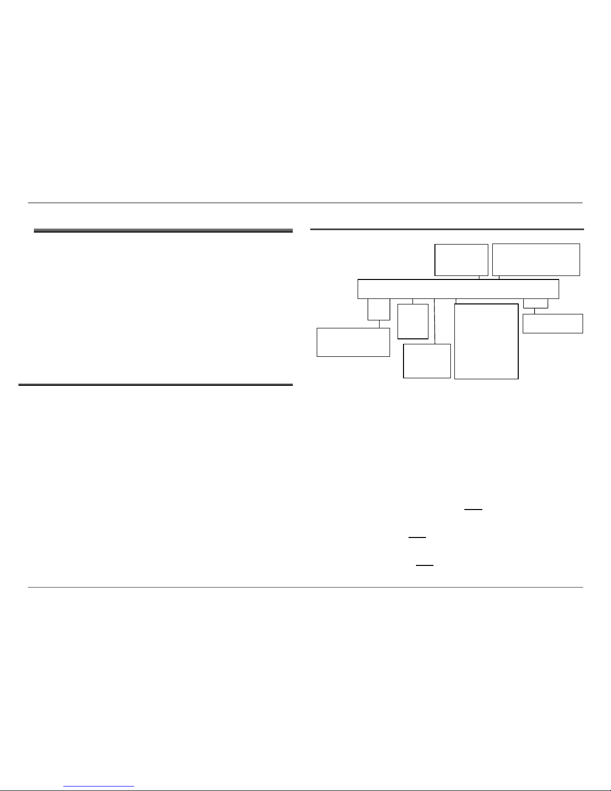
Figure 1 Model number nomenclature
3 GENERAL
The 800 Series includes five HBL8x (30”) and two HBN8x (27”) builtin wall ovens. Models have thermal oven cavities and/or Euroconvection (convection with ring element) cavities. The lineup
includes two field-assembled combination models with either a 120V
Solo Microwave Oven or a 240V Microwave Speed Oven.
Available colors are bright stainless, black stainless, or black
porcelain, and all models feature VFD red and white displays with
touch controls. The wall ovens are designed to be installed flush with
cabinetry.
The control panel and door skins on the stainless models are made of
grade 439 stainless steel, which is magnetic.
3.1 Recap of Functional/Technical Changes
Cooling fan: now operates with a variable speed protocol.
Hall effect sensor has been eliminated, and thermal limiter
(HTC) has been added.
Power supply: now located on the control module (relay
board) rather than as a separate component.
User interface: no longer separate user interface software;
the control module drives the user interface. VFD-based
display with capacitive touch panel managed by a separate
touch control module (TCM).
Daughter board (double ovens only): populated with relays to
operate the lower oven.
Ventilation: air flows up through each door, then back out
over each door as air exits the appliance; some air is pulled
into the unit at the lower vent area under the appliance.
Lighting: Soft lighting is standard on all models. Double oven
lighting is not independent – lights operate concurrently.
Temperature control: now a two-point control for all modes
rather than a PID control for all modes.
Hinges: All models include soft-close doors.
3.2 Models
The model number structure for the 2014 wall ovens appears below.
HBN8451UC 27” Single oven with Euro-convection, stainless
HBN8651UC 27” Double oven with Euro-convection/thermal, stainless
HBL8442UC 30” Single oven with Euro-convection, black stainless
HBL8451UC 30” Single oven with Euro-convection, stainless
HBL8461UC 30” Single oven with Euro-convection, black
HBL8642UC 30” Double oven with Euro-convection/thermal, black
stainless
HBL8651UC 30” Double oven with Euro-convection/thermal, st ai nless
HBL8661UC 30” Double oven with Euro-convection/thermal, black
HBL8742UC 30” Combination oven with 240V speed microwave and
Euro-convection oven, black stainless (oven component
of this model is HBL8742UCC
HBL8752UC 30” Combination oven with 240V speed microwave and
Euro-convection oven (oven component of this model is
HBL8752UCC)
HBL87M52UC 30” Combination oven with120V solo microwave and
Euro-convection oven (oven component of this model is
HBL87M52UCC)
H B L 8 4 5 1 U C
C
LASS
HB=built-in oven
HS=built-in steam oven
S
IZE
L=30”
N=27”
SERIES
5=500
8= 800
P=Benchmark
C
AVITY TYPE
3=Single:
thermal
4=Single:
EU convec
5=Double:
thermal/thermal
6=Double:
EU convec/thermal
or EU convec both
C
OLOR
4=BK SS
5=SS
6=Bk porcelain
V
ARIANT
1=2014 launch
C
OUNTRY
UC = US/Canada
Variant
1=2014 launch
2=2016 / 2017 launch
58300000202443_ARA_EN_C JANUARY 2018 Service Manual for Bosch 800 Series Built-in Wall Ovens
Page 7 of 43
Copyright by BSH Home Appliances Corporation 1901 Main St ▪ Suite 600 ▪ Irvine, CA 92614 800 944-2904
This material is intended for the sole use of BSH authorized persons and may contain confidential and proprietary information. Any unauthorized review, use, copying, disclosure, or distribution in any format is prohibited.
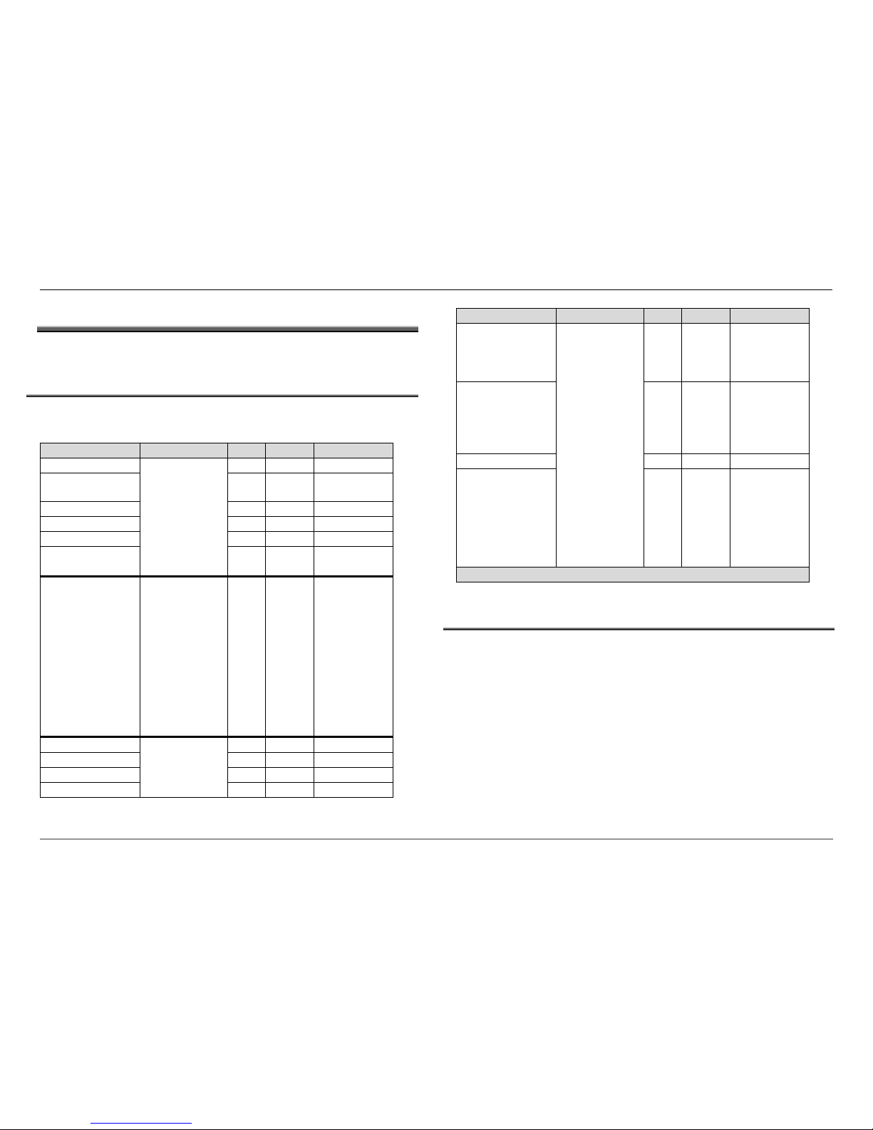
Figure 4 Data plate location
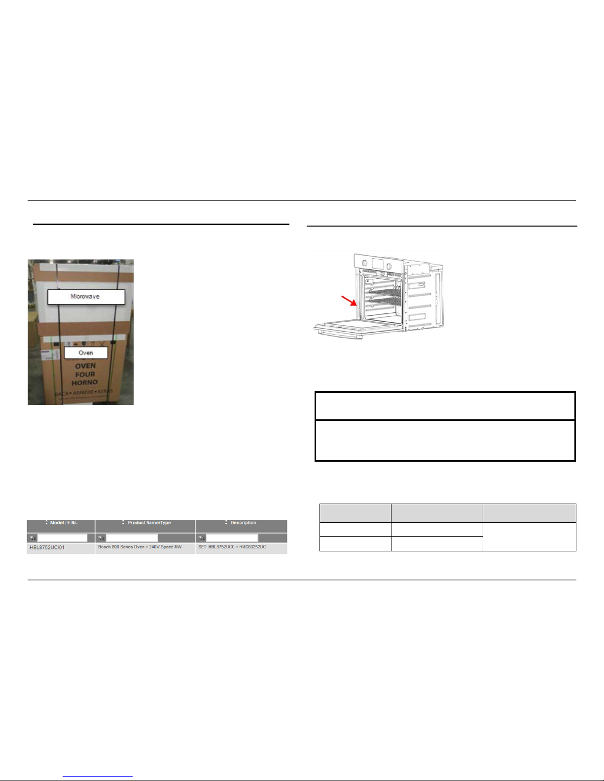
3.2.1 Combination Ovens (Sets)
The 2016 combination ovens (sets) are shipped together as individual
components, and are assembled at the customer’s home during
installation.
Although the combination ovens are sold using the combination
model SKU, the service documentation for the sets can be found
linked to the component models rather than the combination
model SKU. For example, the 800 series combination is sold as an
HBL8752UC, but the service documentation can be found in
QuickFinder linked to its components: HBL8752UCC (wall oven) and
HMC80252UC (microwave speed oven). There is no service
documentation linked to HBL8752UC, but a cross-reference will
appear in QuickFinder when HBL8752UC is entered.
3.3 Rating Label
The rating label reflecting model number and FD number is located on
the side trim, as shown in Figure 4.
The first 4 positions of the FD number reflect the year/month the
product was built. FD numbers that begin with 94 were built in 2014;
95 = 2015; 96 = 2016, etc. FD 9604 = oven built in April 2016.
Note: Some traditional ovens manufactured between April and
October 2016 shipped with numeric model numbers on the rating
labels. See cross-reference table below.
If model number on
Rating Label is…
QuickFinder documents
and manuals are found at
Product description
9001227721/01 HBL87M52UCC/01
800 Series traditional
oven
9001227722/01 HBL8752UCC/01
Table 1 Model No Cross Reference
NOTICE
Be prepared to provide the complete Model Number and FD number
printed on the rating label of the unit when contacting Bosch Customer
Support or Technical Support for assistance.
Figure 2 Combination ovens (sets) ready to be shipped
Figure 3 QuickFinder screen shot

58300000202443_ARA_EN_C JANUARY 2018 Service Manual for Bosch 800 Series Built-in Wall Ovens
Page 8 of 43
Copyright by BSH Home Appliances Corporation 1901 Main St ▪ Suite 600 ▪ Irvine, CA 92614 800 944-2904
This material is intended for the sole use of BSH authorized persons and may contain confidential and proprietary information. Any unauthorized review, use, copying, disclosure, or distribution in any format is prohibited.
3.4 Warranty
The product is warranted to be free from defects in materials and
workmanship for a period of 365 days from date of purchase.
Bosch will have no responsibility or liability for repairs or work
performed by a non-authorized servicer.
Find the complete Statement of Limited Product Warranty in the
product’s Use and Care Manual.
58300000202443_ARA_EN_C JANUARY 2018 Service Manual for Bosch 800 Series Built-in Wall Ovens
Page 9 of 43
Copyright by BSH Home Appliances Corporation 1901 Main St ▪ Suite 600 ▪ Irvine, CA 92614 800 944-2904
This material is intended for the sole use of BSH authorized persons and may contain confidential and proprietary information. Any unauthorized review, use, copying, disclosure, or distribution in any format is prohibited.
4 OPERATION
This section includes basic information about how the 800 Series wall
ovens operate.
4.1 Allowable Operating Range by Cooking Mode
Table 2 reflects the minimums and maximums by cooking mode for
each model in the 800 Series.
Cooking Mode
Models
Min
Max
Default
Bake
All
100°F
550°F
350°F
Broil (Low 450°F /
High 550°F)
450°F 550°F High
Roast
100°F
550°F
325°F
Warm
140°F
225°F
170°F
Sabbath
100°F
425°F
N/A
Self-Cleaning
2
hours
4 hours 3 hours
Proof Dough
HBL8442UC
HBL8451UC
HBL8461UC
HBN8451UC
HBL8642UC(u)
HBL8651UC(u)
HBL8661UC(u)
HBN8651UC
HBL8742UCC
HBL8752UCC
HBL87M52UCC
85°F 125°F 100°F
Convection Bake
HBL8442UC
HBL8451UC
HBL8461UC
HBN8451UC
100°F
550°F
325°F
Convection Broil
450°F
550°F
High
Convection Roast
100°F
550°F
325°F
Pizza
100°F
550°F
400°F
Cooking Mode
Models
Min
Max
Default
Multi-Rack
Convection
(Eur. Conv.)
HBL8642UC(u)
HBL8651UC (u)
HBL8661UC (u)
HBN8651UC(u)
HBL8752UCC
HBL87M52UCC
HBL8442uc
HBL8451UC
HBL8461UC
HBN8451UC
HBL8642UC(u)
HBL8651UC (u)
HBL8661UC (u)
HBN8651UC(u)
HBL8742UCC
HBL8752UCC
HBL87M52UCC
100°F 550°F 325°F
Fast Preheat N/A N/A
Not available
for Broil, Conv
Broil, Proof
Dough or
Warm
Probe
100°F
200°F
N/A
Convection
Conversion
N/A N/A
Auto Temp
Reduction by
25°F
(u) = upper oven only
4.2 Heating Elements
All ovens include an 8-pass 3800W broil element and a 4-pass
2400W bake element. Models with Euro-convection include a 2000W
ring element as well.
When the door is opened, all heating elements (and the convection
fan, if applicable) will be paused. When the door is closed, cycling will
continue.
Table 2 Allowable range by cooking mode
58300000202443_ARA_EN_C JANUARY 2018 Service Manual for Bosch 800 Series Built-in Wall Ovens
Page 10 of 43
Copyright by BSH Home Appliances Corporation 1901 Main St ▪ Suite 600 ▪ Irvine, CA 92614 800 944-2904
This material is intended for the sole use of BSH authorized persons and may contain confidential and proprietary information. Any unauthorized review, use, copying, disclosure, or distribution in any format is prohibited.
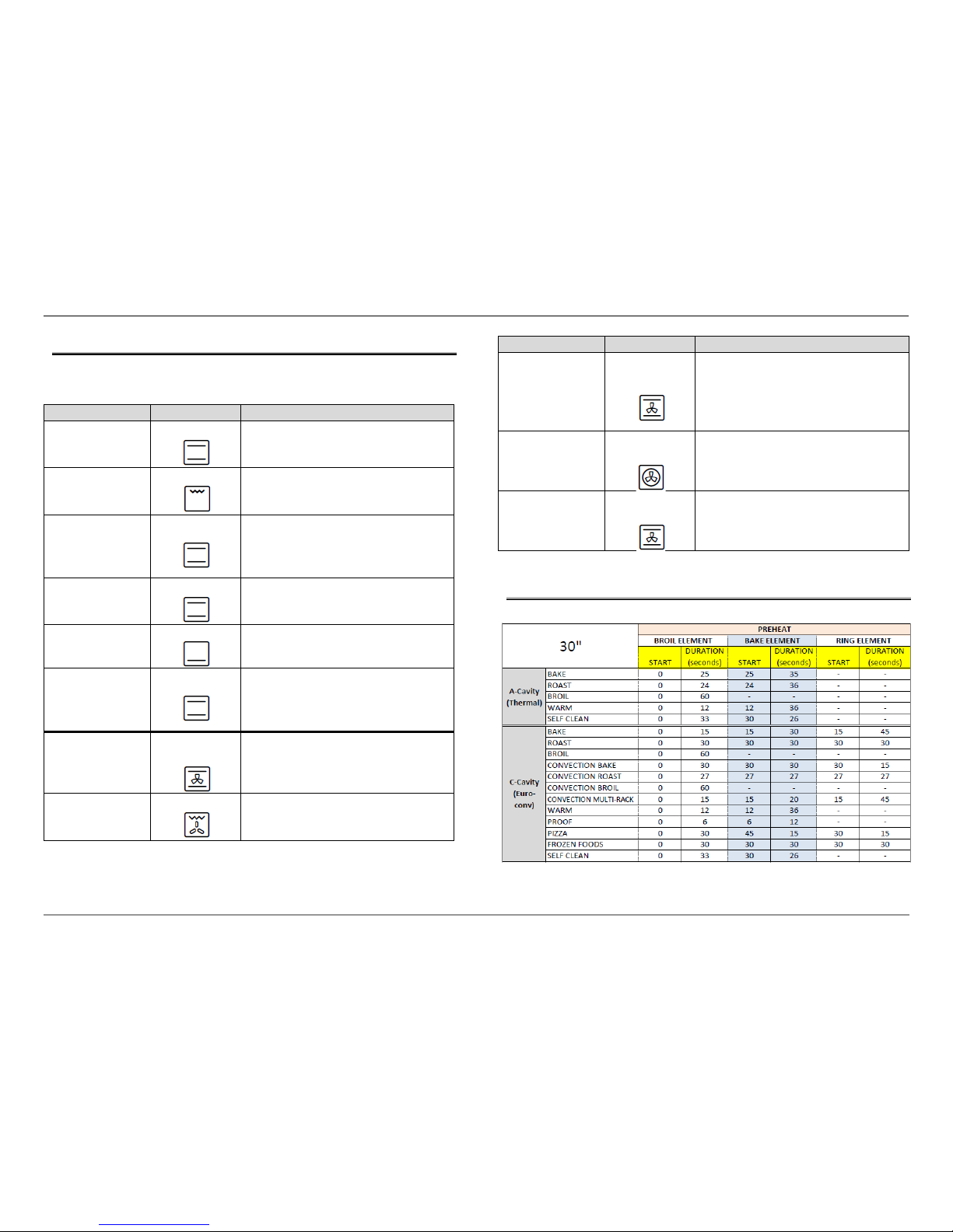
4.2.1 Elements Used by Cooking Mode
The table below reflects the elements which are used for each
cooking mode.
Cooking Mode
Elements Used
Description
Bake
Broil, Bake
Upper and lower elements cycle to
maintain oven temperature
Broil
Broil
Intense heat is radiated from the upper
element
Roast
Broil, Bake
Upper and lower elements cycle to
maintain oven temperature; more
intense heat from the upper element is
used than the lower.
Warm
Broil, Bake
Upper and lower elements cycle to
maintain a low oven temperature
Proof Dough
Bake
Lower element is used to maintain a low
temperature
Self-clean
Broil, Bake
Upper and lower elements cycle to
maintain oven temperature; more
intense heat from the upper element is
used than the lower.
Convection Bake
Broil, Bake,
Conv Fan
Upper and lower elements cycle to
maintain oven temperature, and the
heat is circulated by the convection fan
Convection Broil
Broil, Conv Fan
Intense heat is radiated from the upper
element and the convection fan
circulates the air
Cooking Mode
Elements Used
Description
Convection Roast
Broil, Bake,
Conv Fan
Upper and lower elements cycle to
maintain oven temperature and air is
circulated by the convection fan; more
intense heat from the upper element is
used than the lower.
Convection Multirack
Conv Element,
Conv Fan
Heat is generated by the convection ring
element and circulated by the
convection fan.
Pizza
Broil, Bake,
Conv Fan
Upper and lower elements cycle to
maintain oven temperature, and the
heat is circulated by the convection fan
4.2.2 Element Duty Cycles
A two-point control is used for all cooking modes.
Table 3 Active elements by cooking mode
Table 4 Element duty cycles during Preheat
58300000202443_ARA_EN_C JANUARY 2018 Service Manual for Bosch 800 Series Built-in Wall Ovens
Page 11 of 43
Copyright by BSH Home Appliances Corporation 1901 Main St ▪ Suite 600 ▪ Irvine, CA 92614 800 944-2904
This material is intended for the sole use of BSH authorized persons and may contain confidential and proprietary information. Any unauthorized review, use, copying, disclosure, or distribution in any format is prohibited.
4.2.3 Setting Temperature Offsets
In some cases, it may be necessary to adjust the oven temperature if
the customer reports that food is consistently under- or over-cooked,
even though the oven is operating normally. Temperature Offsets can
be entered by the customer from the Customer Settings menu to raise
or lower the cavity temperature during operation in modes other than
Broil, Convection Broil, Warm, Pizza or Self-clean.
The allowable Offset range is from 0°F to 35°F, positive or negative.
1. Press Settings to access the Customer Settings menu (from
stand-by mode only)
2. Press 9 for Temperature Offset (single/upper) or 10 (lower).
3. Press Enter to edit the current setting.
4. Press (-) or (+) then enter the offset value using the numeric
keys - always enter the value as 2 digits (i.e, 05).
The new value is saved when the display changes from edit
mode back to display mode.
5. Press Oven Clear/Off to exit the Settings menu on single ovens
or press Upper Clear/Off or Lower Clear/Off to exit the Settings
menu on double ovens.
Example: A +25° offset will result in a cavity temperature of 350°
when the cooking temperature is set to 325° for any of the cooking
modes affected by the Offset. Similarly, a -25° offset will result in a
cavity temperature of 300° when the cooking temperature is set to
325°.
The adjusted temperature cannot be less than the minimum allowable
temperature for the cooking mode, nor higher than the maximum for
the cooking mode. See Allowable Operating Range by Cooking Mode
section.
For double ovens, a temperature offset may be set for each oven.
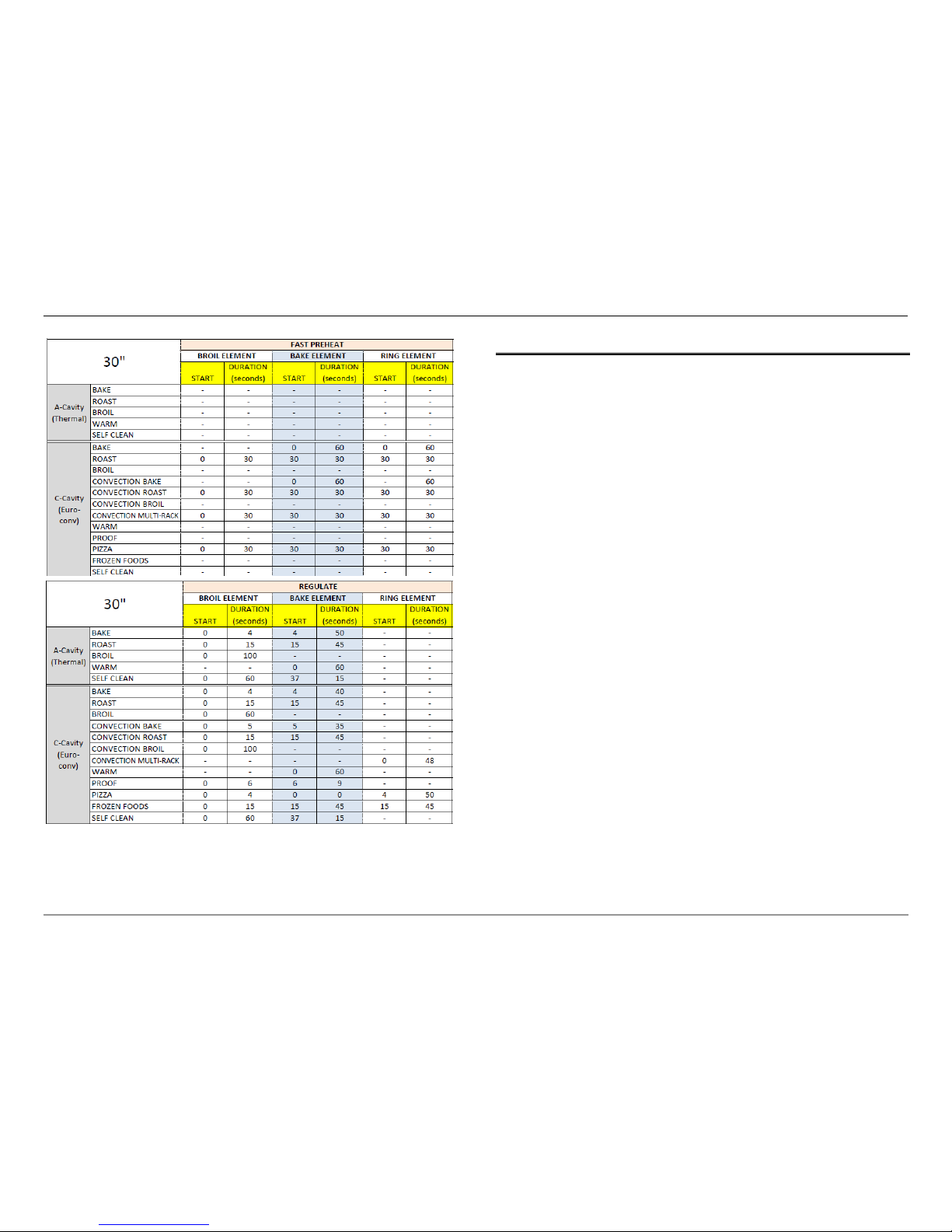
Table 5 Element duty cycles during Fast Preheat
Table 6 Element duty cycles during Regulate

58300000202443_ARA_EN_C JANUARY 2018 Service Manual for Bosch 800 Series Built-in Wall Ovens
Page 12 of 43
Copyright by BSH Home Appliances Corporation 1901 Main St ▪ Suite 600 ▪ Irvine, CA 92614 800 944-2904
This material is intended for the sole use of BSH authorized persons and may contain confidential and proprietary information. Any unauthorized review, use, copying, disclosure, or distribution in any format is prohibited.
4.3 Self-clean
In a double oven, if Self-clean is running in one cavity, the second
cavity will be disabled until the cycle finishes.
4.4 Cooling Fan
The cooling fan will operate during any cooking mode and is used to
maintain allowable temperatures on internal components and
customer-accessible surfaces.
During Preheat, the fan speed will increase based on cavity
temperature until the final speed is reached at the conclusion of
Preheat. Throughout the Regulate phase of the cooking cycle, the fan
speed will remain constant.
During Self-clean, the cooling fan will run at high speed immediately
after the self-clean cycle begins, regardless of temperature. The fan
will remain at this speed for the entire self-clean cycle.
When any of the following errors occur, the cooling fan will operate at
100% until the error is cleared: E101/E201, E002/E302, E303,
E104/E204. See the Error Code Table for more information about
these error codes.
The cooling fan will run until the cavity temperature is cooler than
350 °F (175°C) and will continue to operate after any cooking mode is
completed and the oven is OFF, for 5 minutes, even if the cavity
temperature did not reach 350 °F (175°C).
58300000202443_ARA_EN_C JANUARY 2018 Service Manual for Bosch 800 Series Built-in Wall Ovens
Page 13 of 43
Copyright by BSH Home Appliances Corporation 1901 Main St ▪ Suite 600 ▪ Irvine, CA 92614 800 944-2904
This material is intended for the sole use of BSH authorized persons and may contain confidential and proprietary information. Any unauthorized review, use, copying, disclosure, or distribution in any format is prohibited.
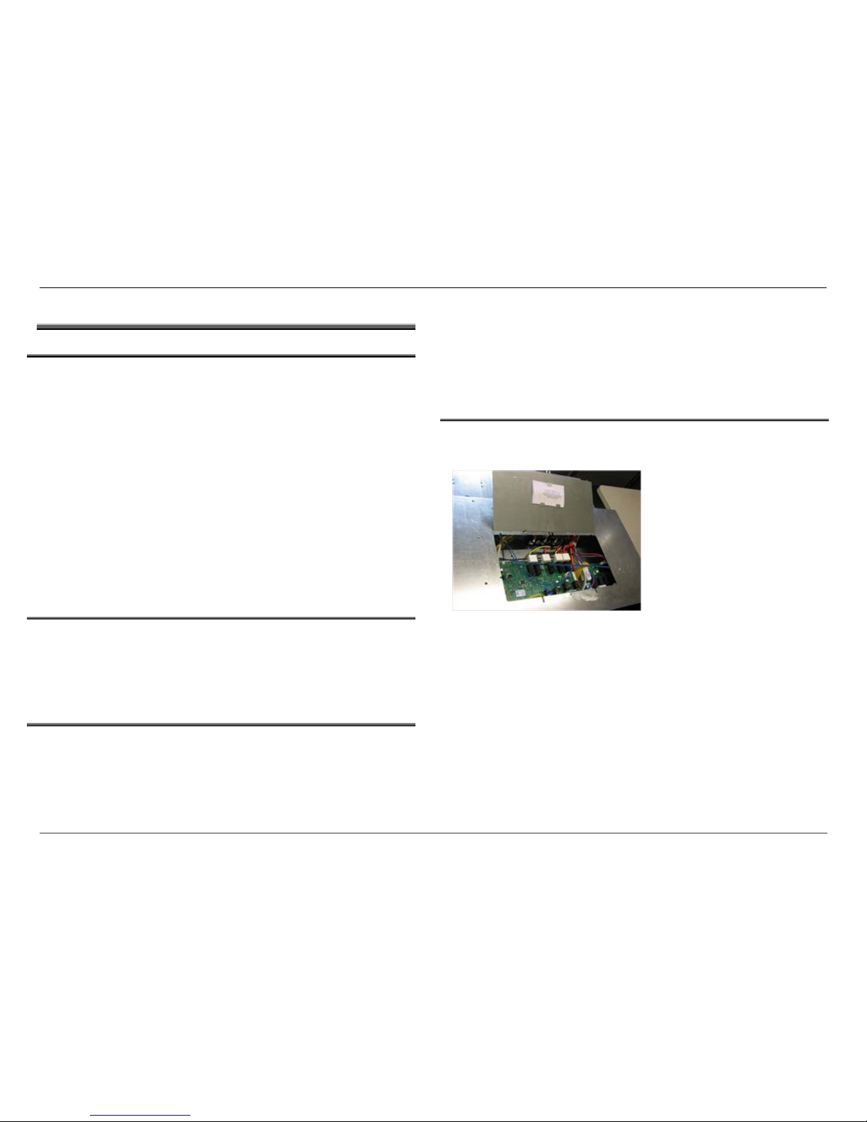
Figure 5 Service panel with Service Guide (w ir e dia gram) attached to the inside of the panel.
5 COMPONENT ACCESSIBILITY
5.1 Serviceable from the Front
Front panel (service assembly includes skin, touch pad, touch
control module (TCM))
Display module
Switches
Door
Door latch/motor assembly
Resettable High Temperature Cutout (HTC) *
Convection fan blade
Convection ring element **
Temperature sensor
Smoke eliminator (catalyst)
Broil reflector and element **
*
If it is not possible to service the resettable HTC through the latch plate
opening, see the Resetting and Replacing the HTC section.
**
If the broil or convection ring element wires are too short to service f rom
the front, access to the rear of the oven will be required.
5.2 Serviceable from the Side
With the unit pulled completely away from the back wall and the side
housing panel(s) and trim removed, the following components are
serviceable…
Hinge receivers
Meat probe receptacle
5.3 Serviceable from the Rear
With the unit pulled completely out of the cutout and the back housing
panel(s) removed, the following components can be serviced from the
rear…
Convection fan motor
Convection ring element *
Broil element *
Bake element
Cooling fan
Cavity lamp receptacle(s)
*
If the broil or convection ring element wires are too short to ser vice from the
front, access to the rear of the oven will be required.
5.4 Serviceable from the Top
There is a service panel located on the top front housing cover. With
the service panel open, there is limited access to the top front plenum
area. The control module is accessible for troubleshooting purposes.
The HBL8752UCC, HBL8742UCC, and HBLHBL87M52UCC
combination oven component includes a pair of service slides
mounted to the top of the oven, which enable the upper microwave
speed oven to slide toward the rear ~7” if it becomes necessary to
access the lower oven service panel. See Top Access: Combination
Models for additional information.
The following components are located in the front area of the top
plenum, and it may be possible to service them through the service
panel without removing the top front and/or rear housing cover(s)…
Control module (relay board)
Daughter board (double ovens only)
Terminal block
 Loading...