

Bosch GST 100 B, GST 100 BCE Instructions Manual
OEU • BA 2 609 931 870 • GST 100 BCE • OSW 03/00 • Titelseiten
Robert Bosch GmbH
Geschäftsbereich Elektrowerkzeuge
D-70745 Leinfelden-Echterdingen
2 609 931 870
Printed in Switzerland - Imprimé en Suisse
Chlor
GST 100 B
GST 100 BCE
2 607 010 079 0 603 035 5..
(5 x) (MT 65)
2 607 001 082 2 600 793 009
(3 m)
1 602 317 002 2 605 438 395
(1,4 m)
2 607 001 069
6...11
12...17
18...23
24...29
30...35
36...41
42...47
42...47
48...53
54...59
60...65
66...71
72...77
78...83
D
GB
PL
CZ
SK
H
RUS
UA
RO
BG
YU
SLO
HR
BY
A
12
17
13
4
5
6
7*
8
9
10
11
12
13
14
15
1
2
3
16*
19*
18
19*
B C
D E
F G
6
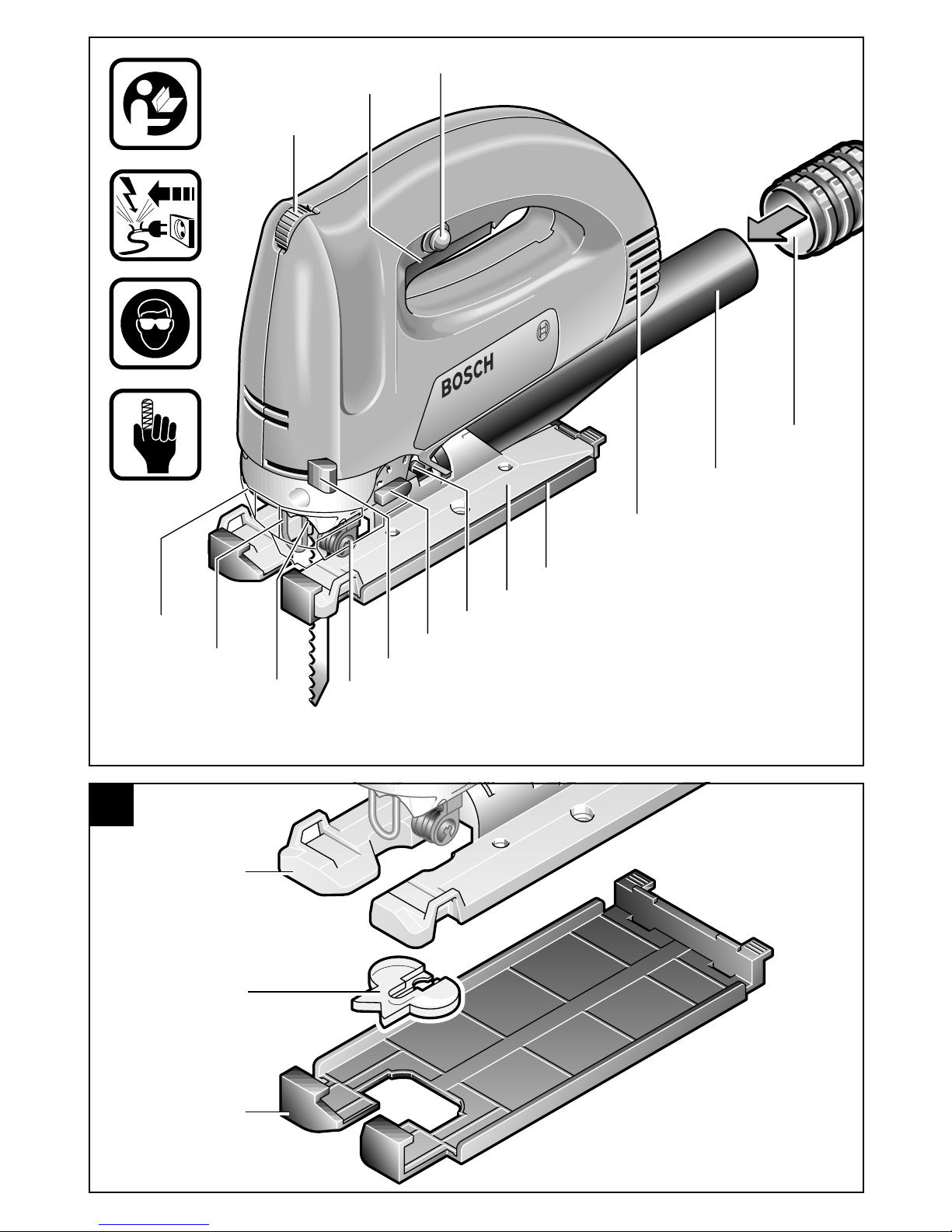
1 Stellrad Hubzahlvorwahl (GST 100 BCE)
2 Ein-Aus-Schalter / Stufenlose
Hubzahlregulierung (GST 100 BCE)
3 Feststellknopf
4 Abdeckhaube für Absaugung
5 Berührungsschutz
6 Hubstange
7 Sägeblatt*
8 Führungsrolle
9 SDS-Hebel für Sägeblattentriegelung
10 Hebel für Pendelhubeinstellung
11 Schalter für Späneblasvorrichtung
12 Fußplatte
13 Gleitschuh für Fußplatte
14 Lüftungsschlitze
15 Absaugstutzen
16 Absaugschlauch*
17 Spanreißschutz
18 Schraube
19 Parallelanschlag/Kreisschneider*
*Zubehör
Abgebildetes oder beschriebenes Zubehör gehört
teilweise nicht zum Lieferumfang.
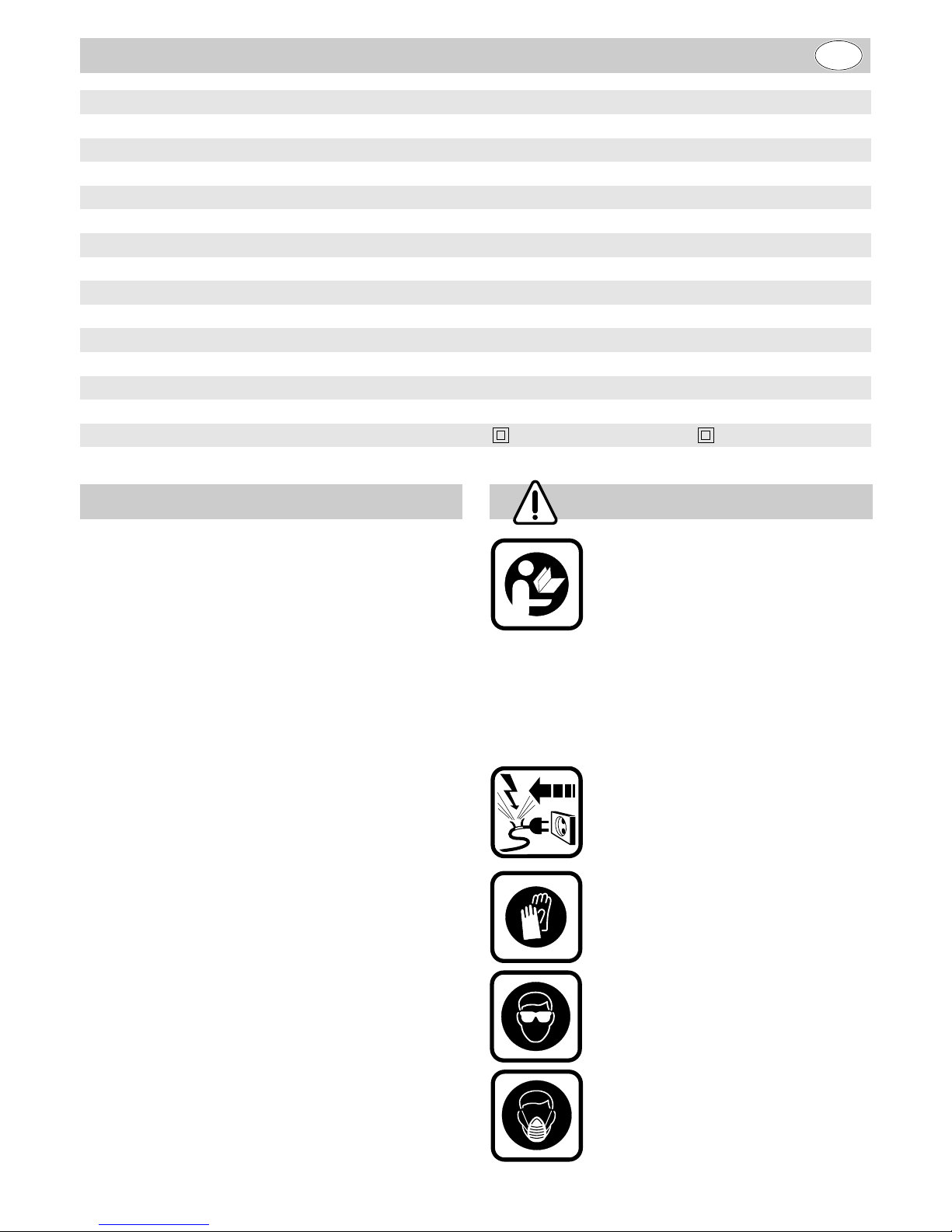
Gefahrloses Arbeiten mit dem
Gerät ist nur möglich, wenn Sie
die Bedienungsanleitung und die
Sicherheitshinweise vollständig
lesen und die darin enthaltenen
Anweisungen strikt befolgen.
Zusätzlich müssen die allgemeinen Sicherheitshinweise im beigefügten Heft beachtet werden.
Lassen Sie sich vor dem ersten
Gebrauch praktisch einweisen.
Wird bei der Arbeit das Netzkabel
beschädigt oder durchtrennt, Kabel
nicht berühren sondern sofort den
Netzstecker ziehen. Gerät niemals
mit beschädigtem Kabel benutzen.
Zum Einsetzen und Wechseln des
Sägeblattes 7 Schutzhandschuhe
tragen.
Beim Bearbeiten stark spanerzeugender Materialien Schutzbrille tragen.
Bei Arbeiten, bei denen gesundheitsgefährdende Stäube entstehen, ist eine Staubschutzmaske zu
tragen. Asbesthaltiges Material darf
nicht bearbeitet werden.
Gerätekennwerte
Pendelhubstichsäge GST 100 B GST 100 BCE
Bestellnummer 0 601 589 0.. 0 601 589 8..
Nennaufnahme 600 W 650 W
Abgabeleistung 370 W 400 W
Leerlaufhubzahl 3100 min
-1
500 - 3000 min
-1
Hub 26 mm 26 mm
Hubzahlvorwahl/Constantelectronic – ·
Stufenlose Hubzahlregulierung – ·
Schnittleistung:
· in Holz bis 110 mm bis 110 mm
· in Aluminium bis 20 mm bis 20 mm
· in Stahl, unlegiert bis 10 mm bis 10 mm
Schrägschnitte (links/rechts) 0 - 45 ° 0 - 45 °
Gewicht (ohne Zubehör) 2,3 kg 2,3 kg
Schutzklasse / II / II
Geräteelemente Zu Ihrer Sicherheit
D
7
Beim Arbeiten nie Hand oder Finger vor dem Sägeblatt führen.
Die unsachgemäße Verwendung
von Zubehör, welches nicht für
diesen Gerätetyp bestimmt ist,
erhöht die Unfallgefahr und kann
zur Beschädigung des Gerätes
führen.
■ Geräte, die im Freien verwendet werden, über
einen Fehlerstrom-Schutzschalter (FI-) mit maximal 30 mA Auslösestrom anschließen. Nur
ein für den Außenbereich zugelassenes,
spritzwassergeschütztes Verlängerungskabel
verwenden.
■ Beim Arbeiten das Gerät immer gut festhalten
und für einen sicheren Stand sorgen.
■ Kabel immer nach hinten vom Gerät wegfüh-
ren.
■ Das Gerät nur eingeschaltet gegen das Werk-
stück führen.
■ Die Schnittbahn muß oben und unten frei von
Hindernissen sein.
■ Beim Sägen muß die Fußplatte 12 auf ganzer
Fläche sicher aufliegen. Beim Bearbeiten kleiner oder dünner Werkstücke stabile Unterlage
bzw. Sägetisch verwenden (Zubehör).
■ Nach Beendigung des Arbeitsvorganges, Ma-
schine ausschalten und erst dann ablegen,
wenn diese vollständug zum Stillstand gekommen ist (Rückschlaggefahr).
■ Sägeblatt nach dem Ausschalten nicht durch
seitliches Gegendrücken abbremsen.
■ Nur scharfe, einwandfreie Sägeblätter verwe-
den. Verbogene oder unscharfe Sägeblätter
sofort auswechseln.
■ Bosch kann nur dann die einwandfreie
Funktion des Gerätes zusichern, wenn Original-Zubehör verwendet wird.
Das Gerät ist bestimmt, bei fester Auflage Trennschnitte und Ausschnitte in Holz, Kunststoff, Metall, Keramikplatten und Gummi auszuführen.
Es ist geeignet für gerade und kurvige Schnitte
mit Gehrungswinkel bis 45°.
Die Sägeblattempfehlungen sind zu beachten.
■ Vor allen Arbeiten am Gerät den Stecker
aus der Steckdose ziehen.
Das Gerät ist mit einer BoschSDS (Special-Direct-System)
Spannvorrichtung ausgestattet.
Dies ermöglicht einfaches und
schnelles Wechseln von Sägeblättern ohne zusätzliches Werkzeug.
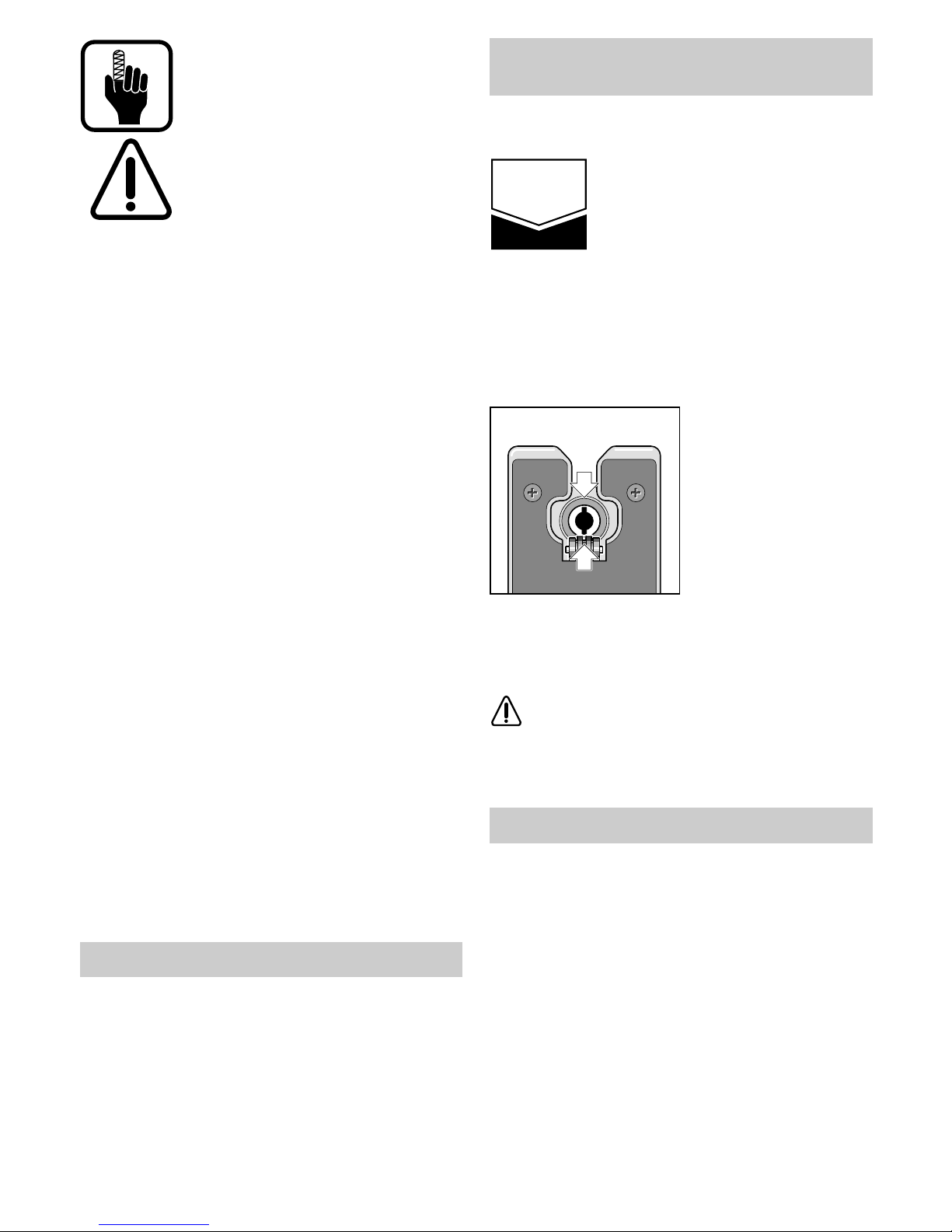
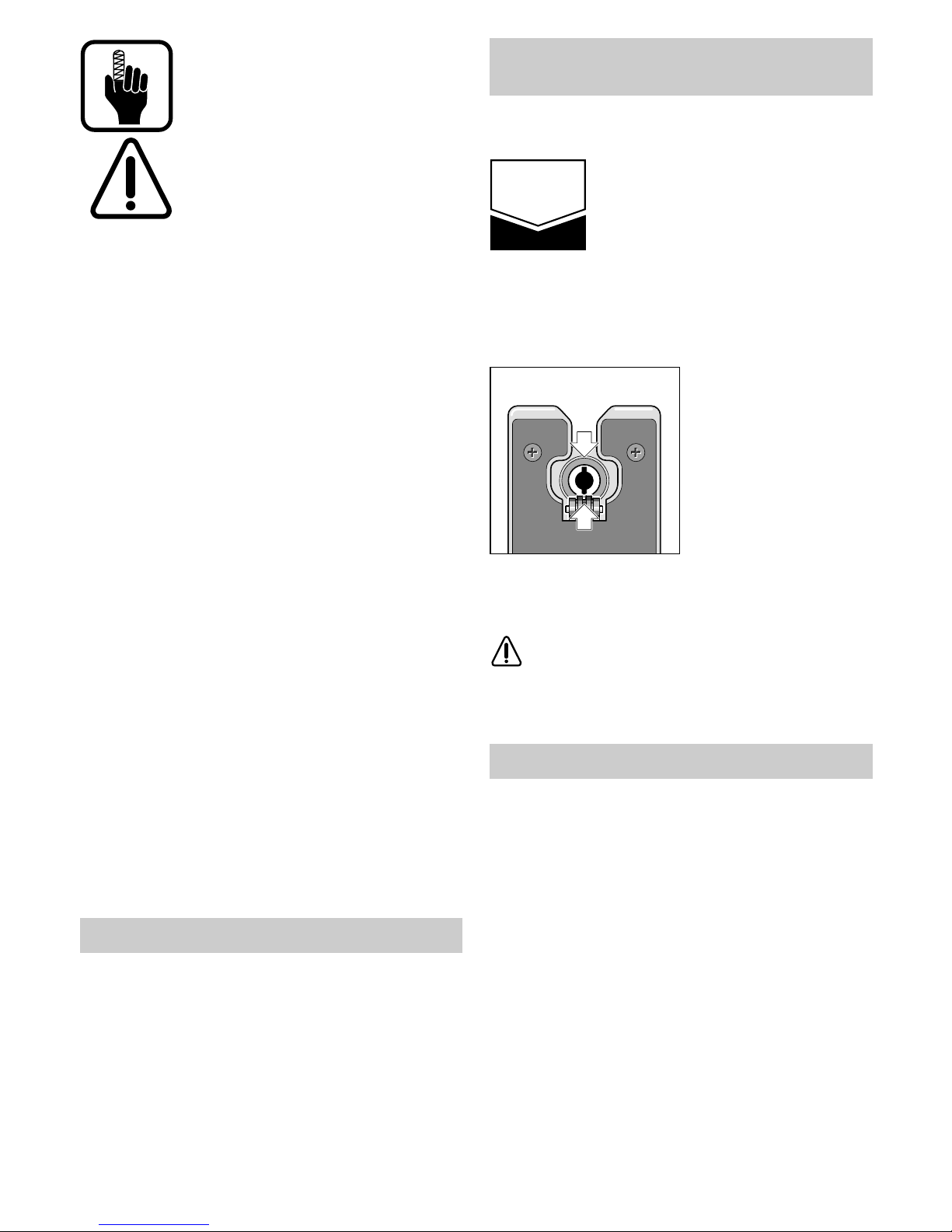
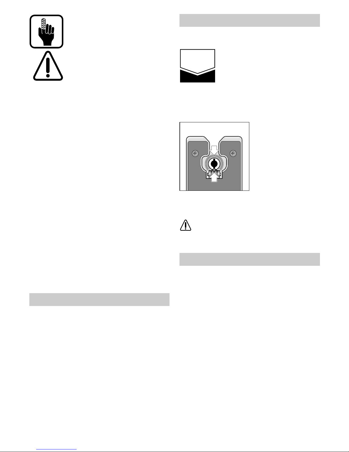
Sägeblatt (Zähne in Schnittrichtung) bis zum Einrasten in Hubstange einschieben. Beim Einsetzen des Sägeblattes darauf achten, daß der Sägeblattrücken in die Rille der Führungsrolle 8
zum Liegen kommt.
Hinweis: Läßt sich
das Sägeblatt nicht in
die Hubstange einführen weil die Nuten der
Sägeblattaufnahme
nicht in der Position
wie gezeigt stehen,
SDS-Hebel kurz nach
vorne schieben und
wieder loslassen.
Zum Wechseln des Sägeblattes den SDSHebel 9 bis zum Anschlag nach vorne schieben;
dadurch wird das Sägeblatt gelöst und ausgeworfen (siehe Bild B).
Beim Sägeblattwechsel ist das Gerät so
zu halten, daß keine Personen oder
Tiere durch das Auswerfen des Sägeblattes verletzt werden können.
Die Spannung der Stromquelle muß mit den Angaben auf dem Typenschild des Gerätes übereinstimmen.
Ein-Aus-Schalten
Momentschaltung
Einschalten: Ein-Aus-Schalter 2 drücken.
Ausschalten: Ein-Aus-Schalter 2 loslassen.
Dauerschaltung
Einschalten: Ein-Aus-Schalter 2 drücken und
in gedrücktem Zustand mit
Feststellknopf 3 arretieren.
Ausschalten: Ein-Aus-Schalter 2 drücken und
loslassen.
Bestimmungsgemäßer Gebrauch
Einsetzen/Wechseln des
Sägeblattes
Inbetriebnahme
SDS
8
Stufenlose Hubzahlregulierung
(GST 100 BCE)
Leichter Druck auf den Ein-/Ausschalter 2 bewirkt
eine niedrige Hubzahl. Mit zunehmenden Druck
wird die Hubzahl erhöht.
Hubzahlvorwahl/Constantelectronic
mit Sanftanlauf (GST 100 BCE)
Mit dem Stellrad 1 läßt sich die benötigte Hubzahl
(auch während des Laufes) vorwählen.
1 - 2 = kleine Hubzahl
3 - 4 = mittlereHubzahl
5 - 6 = große Hubzahl
Die eingebaute Sanftanlauf-Electronic vermeidet
beim Einschalten ruckartiges “Hochlaufen“ des
Gerätes.
Nach kurzem Sanftanlauf regelt das Gerät auf die
vorgewählte Hubzahl ein.
Die Constant-Electronic mit “Tachogenerator“ hält die vorgewählte
Hubzahl auch unter Last nahezu
konstant.
Die erforderliche Hubzahl ist vom Werkstoff und
den Arbeitsbedingungen abhängig und kann
durch praktischen Versuch optimiert werden. Angaben hierzu können Sie auch der im Anhang
aufgeführten Tabelle entnehmen.
Nach längerem Arbeiten mit kleiner Drehzahl, die
Maschine zur Abkühlung zirka 3 Minuten lang mit
maximaler Drehzahl im Leerlauf drehen lassen.
Der am Gehäuse angebrachte Berührungsschutz 5 verhindert unbeabsichtigtes Berühren
des Sägeblattes während des Arbeitsvorganges.
Die Staubabsaugung verhindert
größere Verschmutzungen, hohe
Staubbelastungen in der Atemluft
und erleichtert die Entsorgung des
Schleifstaubes
Bei längerem Bearbeiten von Holz oder bei gewerblichem Einsatz an Materialien, bei denen gesundheitsgefährdende Stäube entstehen, ist das
Gerät an eine geeignete externe Absaugvor-
richtung anzuschließen.
Absaugstutzen
Der Absaugstutzen 15 dient zum Anschluß eines
entsprechend geeignetem Absaugschlauches.
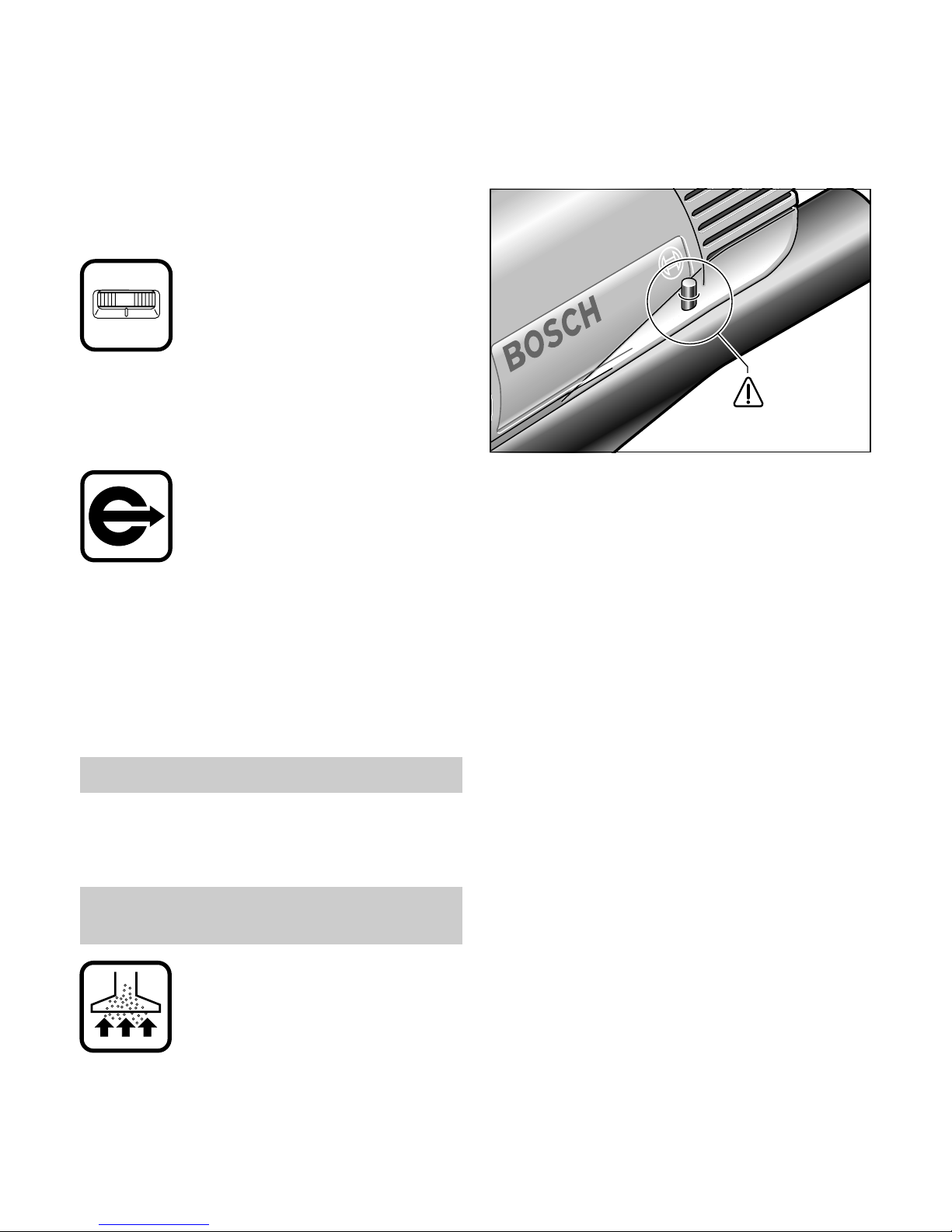
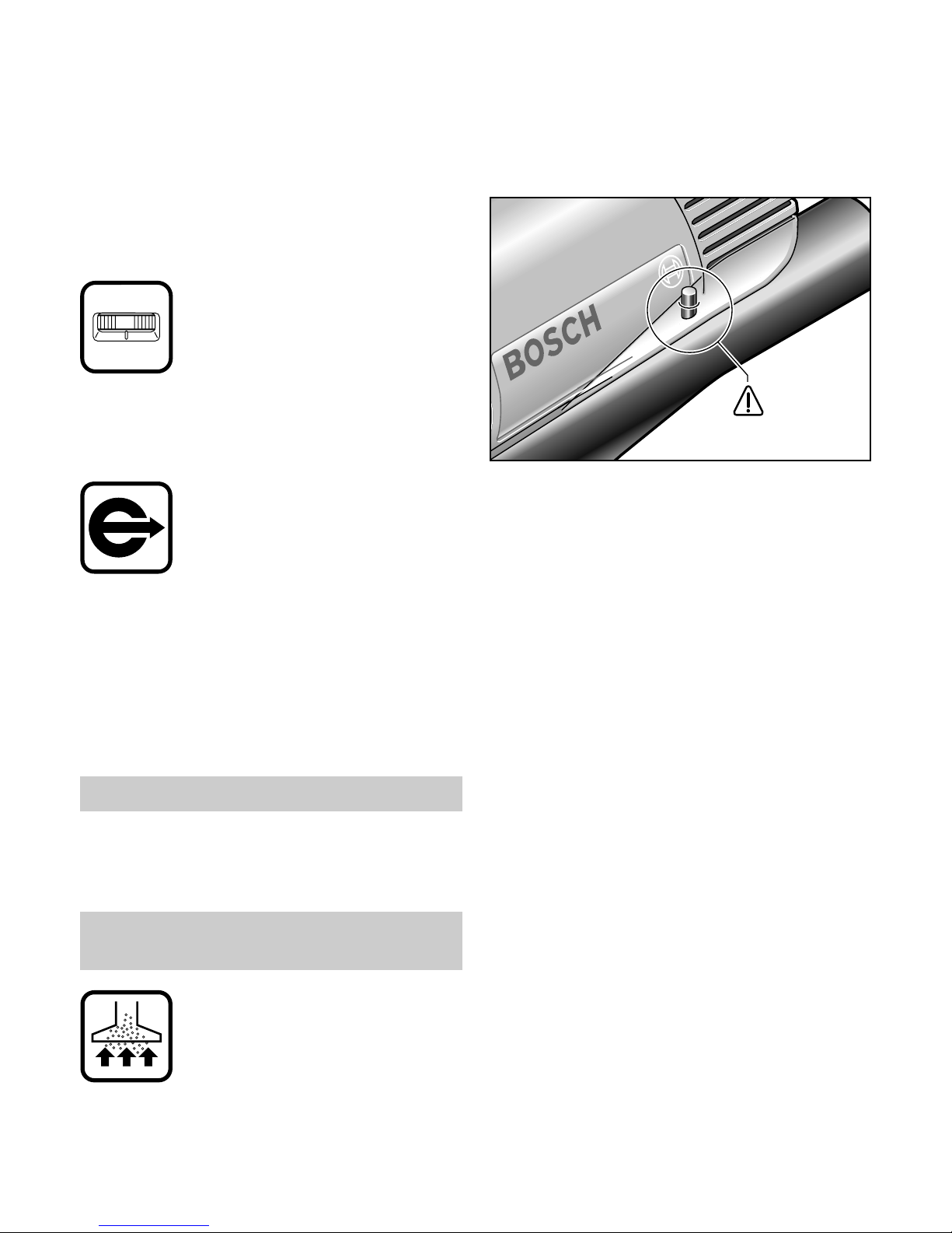
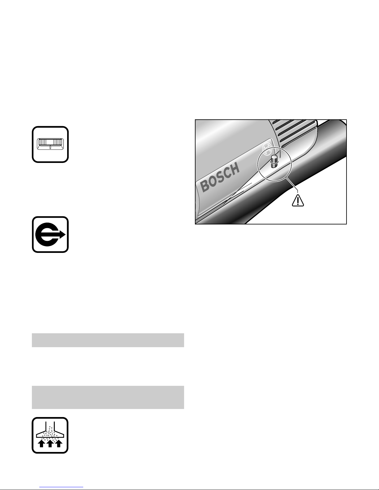
Beim Einsetzen des Absaugstutzens 15 in die
Fußplatte 12 darauf achten, daß die Kunststoffnase des Absaugadapters in die entsprechende
Bohrung am Motorgehäuse eingreift (siehe Bild).
Zum Absaugen kann der 19-mm-ø-Absaugschlauch 16 direkt am Absaugstutzen 15 angeschlossen werden. Bei Verwendung des 35-mm-øAbsaugschlauches muß zusätzlich ein Adapter
(1 600 499 005 - siehe Zubehör) verwendet wer-
den.
Das Gerät kann direkt an der Steckdose eines
Bosch-Saugers mit Fernstarteinrichtung angeschlossen werden. Dieser wird beim Einschalten
des Gerätes automatisch gestartet.
Damit stets optimales Absaugen des Spanmaterials gewährleistet ist, sollten die Absaugkanäle
bzw. der Absaugadapter regelmäßig gereinigt
werden.
Abdeckhaube
Die transparente Abdeckhaube 4 ermöglicht das
Auffangen des Spanmaterials und muß bei Verwendung der Staubabsaugung immer montiert
sein.
Aufsetzen: Abdeckhaube von vorne auf den
Berührschutz 5 aufsetzen und
einrasten lassen.
Abnehmen: Abdeckhaube seitlich fassen; leicht
verkanten und nach vorne
wegziehen.
Berührschutz
Staubabsaugung mit externer
Absaugvorrichtung
1
9
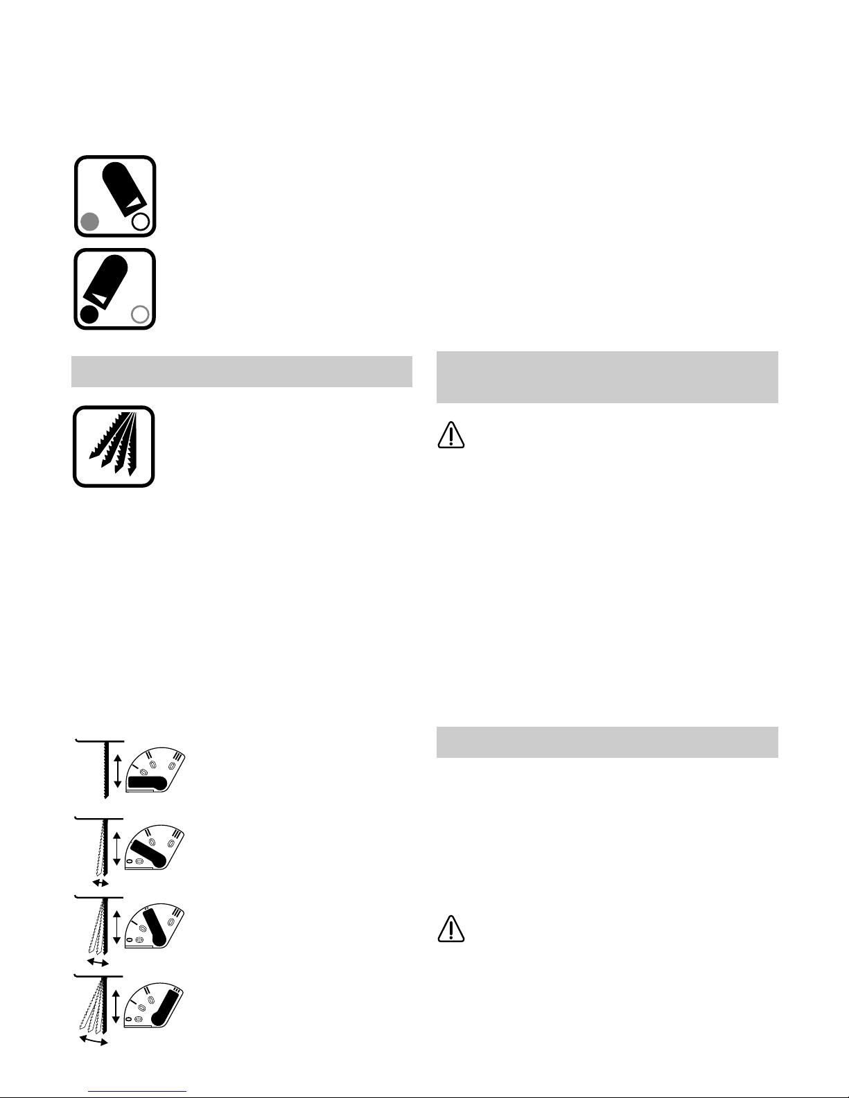
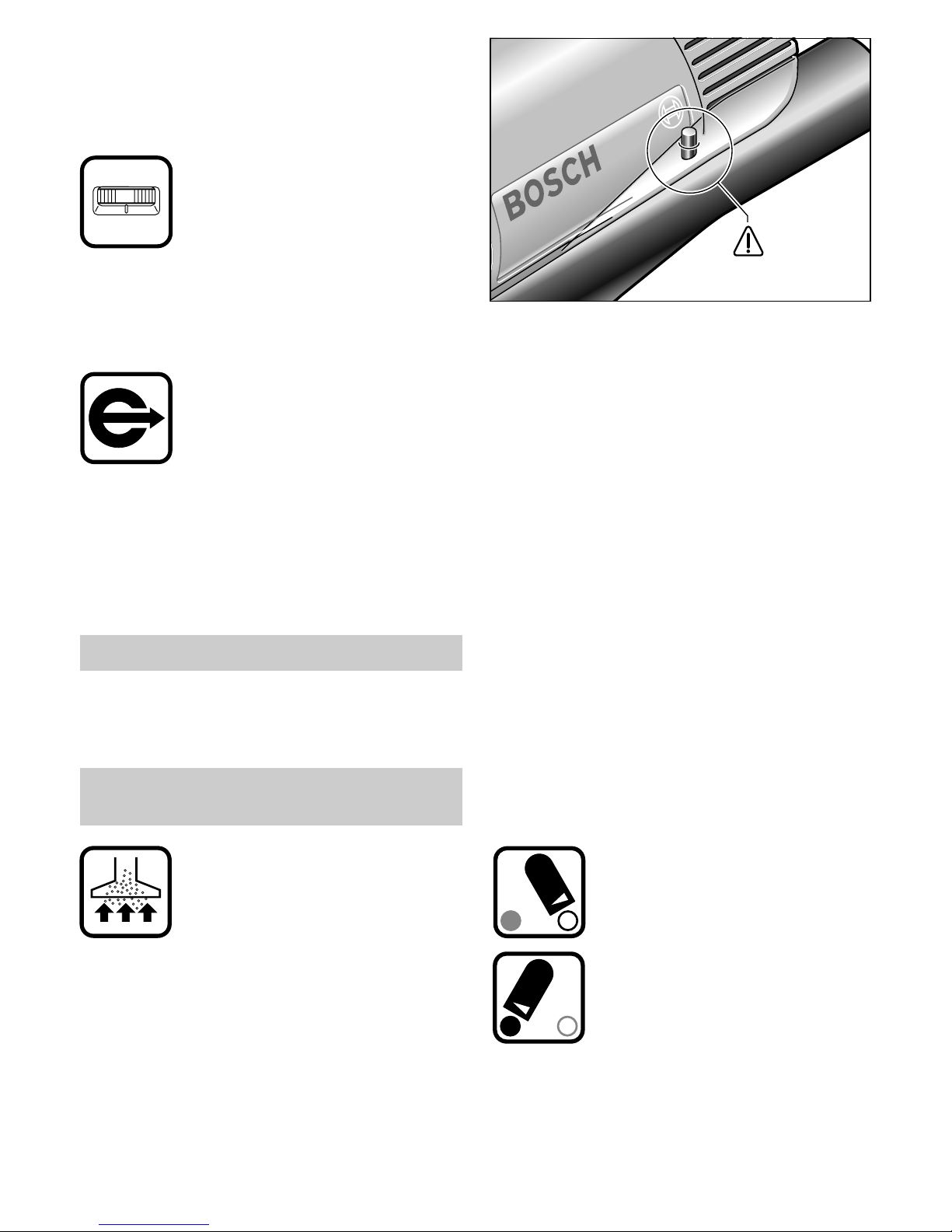
Späneblasvorrichtung
Die Späneblasvorrichtung führt einen Luftstrom
zum Sägeblatt. Dieser verhindert, daß die
Schnittlinie während der Arbeit von Spänen verdeckt wird. Mit Einstellhebel 11 kann der Luftstrom Ein-bzw. Ausgeschaltet werden:
Späneblasvorrichtung Ein:
für Arbeiten in Holz, Kunststoff und
ähnlichen Materialien mit großem
Spanabtrag.
Späneblasvorrichtung Aus:
für Arbeiten in Metallen und Verwendung von Kühl- und Schmierflüssigkeit.
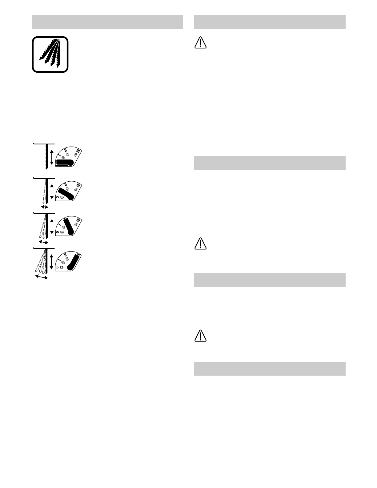
Die in vier Stufen einstellbare Pendelung ermöglicht eine optimale
Anpassung von Sägefortschritt
(Schnittgeschwindigkeit), Schnittleistung und Schnittbild an das zu
bearbeitende Material.
Bei jeder Abwärtsbewegungen wird das Sägeblatt vom Werkstoff abgehoben; dadurch wird der
Spanauswurf begünstigt, die Reibungswärme
verringert und die Lebensdauer des Sägeblattes
erhöht. Gleichzeitig wird durch Verringerung der
notwendigen Vorschubkraft ein ermüdungsfreies
Arbeiten ermöglicht.
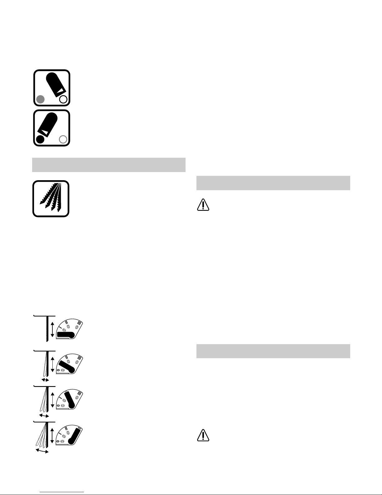
Der Einstellhebel 10 emöglicht die Einstellung
der Pendelung in vier Stufen. Die Umschaltung
kann bei laufender Maschine erfolgen:
Stufe 0:
keine Pendelung
Stufe I:
kleine Pendelung
Stufe II:
mittlere Pendelung
Stufe III:
große Pendelung
Grundsätzlich sind folgende Empfehlungen
zu beachten:
– die Pendelstufe ist umso kleiner zu wählen
bzw. abzuschalten, je feiner und sauberer die
Schnittkante werden soll.
– bei der Bearbeitung von dünnen Werkstoffen
wie z. B. Blechen, Pendelung ausschalten
(Stufe 0).
– in harten Werkstoffen wie z. B. Stahl mit kleiner
Pendelung arbeiten;
– in Werkstoffen wie Weichholz und Schnitt in
Faserrichtung kann mit maximaler Pendelung
gearbeitet werden.
Die optimale Einstellung kann durch praktischen
Versuch ermittelt werden. Angaben hierzu können Sie auch der hintenstehenden Tabelle entnehmen.
Vor Verstellen des Schnittwinkels (z.B.
bei Gehrungsschnitten) den Absaugstutzen 15 entfernen.
Nach Lösen der Schraube 18 und leichtem Vorschieben in Richtung Sägeblatt, ist die
Fußplatte 12 stufenlos bis maximal 45° jeweils
nach links oder rechts schwenkbar.
Nach der Grobeinstellung Schraube 18 soweit
festziehen, daß sich die Fußplatte 12 gerade
noch verstellen läßt. Schnittwinkel genau einstellen, beispielsweise mit Hilfe eines Geodreiecks.
Schraube 18 festziehen.
Beim Zurückstellen der Fußplatte in 0°-(normal)Position, Fußplatte bis zum spürbaren Einrasten
leicht in Richtung Motor drücken und
Schraube 18 wieder festziehen.
Für randnahes Sägen kann die Fußplatte nach
hinten versetzt werden:
Schraube 18 ca. 2 Umdrehungen lösen. Fußplatte bis zum Anschlag nach hinten in Richtung
Motor schieben und Schraube wieder festziehen.
Bei versetzter Fußplatte kan nur in 0°-(normal)-Position gearbeitet werden.
Der Kreisschneider/Parallelanschlag 19
sowie der Spanreißschutz 17 können
dabei nicht verwendet werden.
Pendelung einstellen
Schnittwinkel einstellen (Bild C)
Fußplatte versetzen
☞
10
Der Spanreißschutz 17 verhindert beim Sägen von
Holzwerkstoffen ein Ausreißen der Oberfläche.
Den Spanreißschutz von unten in Fußplatte 12
eindrücken.
Der Spanreißschutz kann für bestimmte
Sägeblatt-Typen (z. B. geschränkte Sägeblätter) nicht verwendet werden.
Die mit einer Stahleinlage ausgerüstete Aluminium-Fußplatte 12 gewährleistet größtmögliche
Stabilität und ist ohne Verwendung des
Gleitschuhs 13 zur Bearbeitung von Metalloberflächen bzw. unempfindlicher Materialien vorgesehen.
Bei Bearbeitung von kratzempfindlichen Materialien vermeidet der Gleitschuh 13 ein Verkratzen
empfindlicher Oberflächen.
Zum Aufsetzen den Gleitschuh vorne an Fußplatte einhängen, hinten hochdrücken und einrasten lassen.
Tauchsägen
Es dürfen nur weiche Werkstoffe wie
Holz, Gasbeton, Gipskarton etc, im
Tauchsägeverfahren bearbeitet werden.
Ausschnitte in Holz sind ohne vorzubohren durch
Einstechen bei laufender Maschine möglich. Dies
erfordert jedoch gewisse Übung und ist nur mit
kurzen Sägeblättern möglich.
Gerät mit der vorderen Kante der Fußplatte auf
das Werkstück aufsetzen und einschalten. Gerät
fest gegen das Werkstück drücken und Sägeblatt
langsam in das Werkstück eintauchen (Bild F).
Nach Erreichen der erforderlichen Schnittiefe,
Gerät wieder in normale Arbeitsstellung bringen,
so daß die Fußplatte ganzflächig aufliegt und entlang der Schnittlinie weitersägen (Bild G).
Nach dem Arbeitsvorgang, Gerät erst ausschalten und anschließend aus dem Schnitt ziehen.
Kreisschneider/Parallelanschlag
(Zubehör)
Mit dem kombinierten Kreisschneider/-
Parallelanschlag 19 können Sie kreisrunde Aus-
schnitte oder Parallelschnitte bis zu einer Materialstärke von 30 mm machen (siehe Bild D/E).
Für enge Kurven verwenden Sie am besten
schmale Sägeblätter. Geeignete Typen können
Sie den Tabellen auf den hinteren Seiten entnehmen.
Wegen der beim Sägen von Metall auftretenden
Erwärmung entlang der Schnittlinie Kühl- bzw.
Schmiermittel auftragen.
■ Vor allen Arbeiten am Gerät den Stecker aus
der Steckdose ziehen.
■ Gerät und Lüftungsschlitze stets sauberhalten,
um gut und sicher zu arbeiten.
■ Zur Vermeidung von Funktionsstörungen
durch übermäßige Verschmutzung sollten
stark stauberzeugende Materialien wie z.B.
Gipskarton nicht von unten bzw. über Kopf bearbeitet werden.
■ Um langfristig einen einwandfreien Betrieb des
Gerätes sicherzustellen, ist die SDS-Sägeblattaufnahme daher regelmäßig zu reinigen.
Dies kann beispielsweise durch leichtes Ausklopfen des Gerätes mit seiner Fußplatte auf
einer ebenen Fläche erfolgen.
Bei extremen Einsatzbedingungen (z.B.
beim Bearbeiten von Buntmetallen)
kann sich ein starke Verschmutzung im Inneren des Gerätes aufbauen. Es empfiehlt sich
in solchen Fällen die Verwendung einer stationären Absauganlage, eine Verkürzung der
Reinigungszyklen und das Vorschalten eines
Fehlerstrom (FI)-Schutzschalters.
Die Führungsrolle 8 ist gelegentlich mit einem
Tropfen Öl zu schmieren und auf Abnutzungserscheinungen zu überprüfen. Ist sie abgenützt,
muß sie erneuert werden.
Sollte das Gerät trotz sorgfältiger Herstell- und
Prüfverfahren einmal ausfallen, ist die Reparatur
von einer autorisierten Kundendienststelle für
Bosch-Elektrowerkzeuge ausführen zu lassen.
Bei allen Rückfragen und Ersatzteilbestellungen
bitte unbedingt die 10-stellige Bestellnummer des
Gerätes angeben!
Spanreißschutz
Gleitschuh für Fußplatte
Anwendungstips
Wartung und Reinigung
11
Rohstoffrückgewinnung statt Müllentsorgung
Gerät, Zubehör und Verpackung sollten einer
umweltgerechten Wiederverwertung zugeführt
werden.
Diese Anleitung ist aus chlorfrei gefertigtem Recycling-Papier hergestellt. Zum sortenreinen Recycling sind die Kunststoffteile gekennzeichnet.
In Deutschland können nicht mehr gebrauchsfähige Geräte zum Recycling beim Handel abgegeben oder (ausreichend frankiert) direkt eingeschickt werden an:
Recyclingzentrum Elektrowerkzeuge
Osteroder Landstraße 3
D-37589 Kalefeld
Für Bosch-Geräte leisten wir Garantie gemäß
den gesetzlichen/länderspezifischen Bestimmungen (Nachweis durch Rechnung oder Lieferschein).
Schäden, die auf natürliche Abnützung, Überlastung oder unsachgemäße Behandlung zurückzuführen sind, bleiben von der Garantie ausgeschlossen.
Beanstandungen können nur anerkannt werden,
wenn das Gerät unzerlegt an den Lieferer oder
an eine Bosch-Kundendienstwerkstätte für
Druckluft- oder Elektrowerkzeuge gesandt wird.
Deutschland
Robert Bosch GmbH
Servicezentrum Elektrowerkzeuge
Zur Luhne 2
D-37589 Kalefeld
✆ Service: ........................................ 01 80 - 3 35 54 99
Fax
........................................................ (0 55 53) 20 22 37
✆ Kundenberater:........................ 01 80 - 3 33 57 99
Österreich
ABE Service GmbH
Jochen-Rindt-Straße 1
A-1232 Wien
✆ Service: ............................................ (02 22) 61 03 80
Fax
...................................................... (02 22) 61 03 84 91
✆ Kundenberater:................ (02 22) 7 97 22 30 20
Schweiz
Robert Bosch AG
Kundendienst Elektrowerkzeuge
Industriestrasse 31
CH-8112 Otelfingen
✆ Service: ............................................... (01) 8 47 16 16
✆ Kundenberater:....... Grüne Nr. 0 800 55 11 55
Meßwerte ermittelt entsprechend EN 50 144.
Der A-bewertete Schalldruckpegel des Gerätes
beträgt typischerweise 83 dB (A). Der Geräuschpegel beim Arbeiten kann 85 dB (A) überschreiten. Gehörschutz tragen!
Die Hand-Arm-Vibration ist typischerweise niedriger als 2,5 m/s
2
.
Wir erklären in alleiniger Verantwortung, daß dieses
Produkt mit den folgenden Normen oder normativen
Dokumenten übereinstimmt:
EN 50 144, HD 400 gemäß den Bestimmungen der
Richtlinien 89/336/EWG, 98/37/EG.
Dr. Gerhard Felten Dr. Eckerhard Strötgen
Robert Bosch GmbH, Geschäftsbereich Elektrowerkzeuge
Umweltschutz
Garantie
Service und Kundenberater
Geräusch-/Vibrationsinformation
Konformitätserklärung
Änderungen vorbehalten
12
1 Stroke rate selection thumbwheel
(GST 100 BCE)
2 On/Off switch / Infinitely-variable stroke rate
adjustment (GST 100 BCE)
3 Locking button
4 Dust cover for vacuuming
5 Contact protector
6 Stroke rod
7 Saw blade*
8 Guide roller
9 SDS lever for saw blade release
10 Lever for pendulum stroke adjustment
11 Switch for sawdust blower
12 Base plate
13 Glide shoe for base plate
14 Ventilation slots
15 Vacuuming connector piece
16 Vacuum hose*
17 Splintering protector
18 Screw
19 Circle cutter / Parallel guide*
*Accessory
Not all of the accessories illustrated or described are
included as standard delivery.
Working safely with this machine is possible only when the
operating and safety information
are read completely and the instructions contained therein are
strictly followed.
In addition, the general safety
instructions in the enclosed
booklet must be followed. Before using for the first time, ask
for a practical demonstration.
If the cable is damaged or cut
through while working, do not touch
the cable but immediately pull the
mains plug. Never use the machine
with a damaged cable.
For the mounting and replacing of
the saw blade 7, wear protective
gloves.
Wear protective goggles when
working with materials which produce large amounts of chips..
For work which produces dust that
is detrimental to health, a dust protection mask should be worn. Materials containing asbestos should not
be worked.
Tool Specifications
Pendulum Action Jigsaw GST 100 B GST 100 BCE
Part Number 0 601 589 0.. 0 601 589 8..
Power input 600 W 650 W
Po wer output 370 W 400 W
Stroke rate at no load 3100 min
-1
500 - 3000 min
-1
Stroke 26 mm 26 mm
Stroke rate selection/Constant electronics – •
Infinitely-variable stroke rate adjustment – •
Cutting ability:
· in wood up to 110 mm up to 110 mm
· in aluminium up to 20 mm up to 20 mm
· in non-alloyed steel up to 10 mm up to 10 mm
Bevel cuts (left/right) 0 - 45 ° 0 - 45 °
Weight 2,3 kg 2,3 kg
Protection class / II / II
Operating Controls For Your Safety
GB
13
When working, never place a hand
or fingers in front of the saw blade.
The improper use of accessories which are not intended for
this machine type increases the
danger of an accident and can
lead to damage to the machine.
■ Connect machines that are used in the open
via a residual current circuit breaker with a triggering current of 30 mA maximum. Use only
extension cables that are intended for outdoor
use and are protected against splash water.
■ When working with the machine, always hold it
firmly with both hands and provide for a secure
stance.
■ Always direct the cable to the rear away from
the machine.
■ Apply the machine to the workpiece only when
switched on.
■ The cutting path must be free of obstacles both
above and blow.
■ When sawing, the complete surface of the
base plate 12 should securely rest on the material. For the working of smaller or thin workpieces, use a stable foundation or a saw table
(accessory).
■ When the cut is completed, switch off the ma-
chine and then pull the saw blade out of the cut
only after it has come to a standstill (danger of
kick-back).
■ After switching off, do not brake the saw blade
to a stop by applying side pressure.
■ Use only sharp, flawless saw blades. Replace
immediately cracked, bent or dull saw blades.
■ Bosch can assure flawless functioning of
the machine only when original accessories are used.
The machine is intended for making separating
cuts and cut-outs in wood, plastic, metal, ceramic
plates and rubber while resting firmly on the workpiece.
It is suitable for straight and curved cuts with mitre angles to 45°.
The saw blade recommendations are to be observed.
■ Before any work on the machine itself,
pull the plug from the socket!
The machine is equipped with a
Bosch SDS (Special Direct System) clamping device. This
makes possible easy and quick
changing of the saw blade without additional tools.
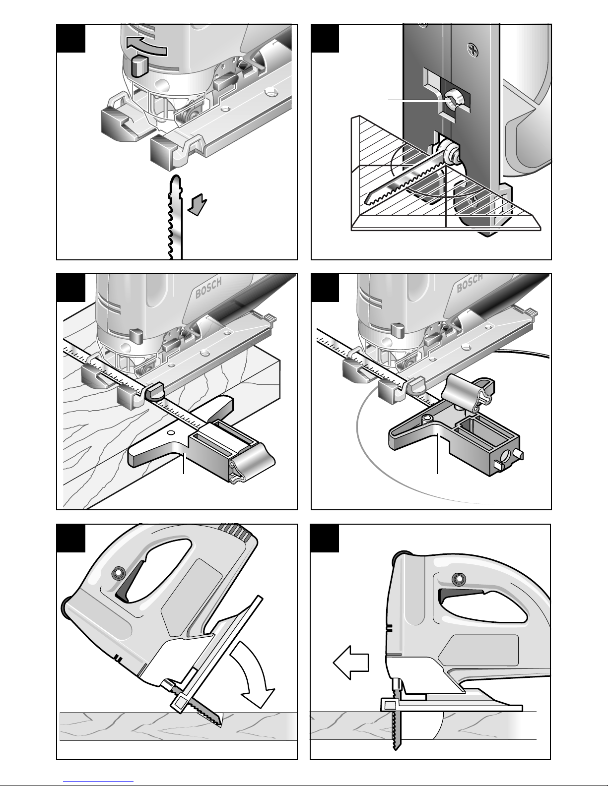
Insert the saw blade (teeth in cutting direction)
until it latches in the stroke rod. When inserting
the saw blade, take care that the back of the saw
blade rests in the groove of the guide roller 8.
Note: If the saw blade
cannot be inserted into
the stroke rod because
the slots of the saw
blade holder are not in
the position as shown,
push the SDS lever
briefly to the front and
release.
To change the saw blade, push the SDS lever 9
to the front to the stop; this releases the saw
blade and it is ejected (see Fig. B).
When changing the saw blade, the machine should be held so that no persons or animals can be injured by the
ejection of the saw blade.
The power supply voltage must match the information quoted on the tool identification plate.
Switching On/Off
Brief activation
Switching on: Press ON-OFF switch 2.
Switching off: Release ON-OFF switch 2.
Continuous use
Switching on: Press ON-OFF switch 2 and
retain with locking button 3.
Switching off: Press and release ON-OFF
switch 2.
Intended Use
Inserting/Replacing the Saw
Blade
Initial Operation
SDS
14
Infinitely-variable stroke rate
adjustment (GST 100 BCE)
Light application of pressure on on/off switch 2
results in low stroke rate. Increasing pressure results in a higher stroke rate.
Stroke Rate Selection/
Constant Electronics with Soft Start
(GST 100 BCE)
With the thumbwheel 1, the required stroke rate
can be selected (also while running).
1 - 2 = Low stroke rate
3 - 4 = Medium stroke rate
5 - 6 = High stroke rate
The built-in soft start electronics prevent a jerking
“Run-up” when the machine is switched on.
After the brief soft run-up, the machine is regulated to the preselected stroke rate.
The Constant Electronics with
“Tach-generator” keeps the preselected stroke rate nearly constant
also under load.
The stroke rate required depends upon the material and the working conditions. The optimal setting can be determined in practice. You can find
relevant information in the following table.
After working for longer periods at low stroke rate
allow the machine to cool by running it at maximum stroke rate and no load for approx. 3 minutes.
The contact protector 5 attached to the machine
prevents unintentional contact with the saw blade
while working.
Dust extraction prevents large accumulations of dust, high concentrations of dust in the ambient air
and facilitates disposal.
For long periods of working with wood or for commercial use on materials that produce dust that is
detrimental to health, the machine is to be connected to a suitable external dust extraction device.
Vacuuming Connector Piece
The vacuuming connector piece 15 serves for the
connecting of a suitable vacuum hose.
When inserting the connection piece 15 into the
base plate 12, take care that the plastic nose of
the vacuuming adapter engages in the corresponding hole on the motor housing (see Figure).
For vacuuming, a Bosch 19 mm dia. vacuum
hose 16 can be directly connected to the connector piece 15. The use of a 35 mm dia. vacuum
hose requires that an additional adapter be use
(1 600 499 005 - see accessories).
The machine can be connected directly to the
socket of a Bosch all-purpose vacuum cleaner
with a remote starting device. The vacuum
cleaner is started automatically when the machine is switched on.
So that optimum vacuuming of the sawdust is ensured, the vacuum channels and the vacuuming
adapter should be cleaned regularly.
Dust Cover
The transparent dust cover 4 makes possible the
collecting of the sawdust and must always be
mounted when dust vacuuming is used.
Mounting: Place the cover from the front onto
the contact protector 5 and snap on.
Removal: Take hold of the cover at the sides,
tilt slightly and pull off to the front.
Contact Protector
Dust Vacuuming with the
External Extractor Device
1
15
Sawdust Blower
The sawdust blowing device directs a stream of
air at the saw blade. This prevents the cut line
from being covered by sawdust while working.
The air stream can be adjusted to one of three
levels with adjustment lever 11:
Blower effect switched on:
For working with wood, plastic and
similar materials that produce large
amounts of sawdust.
Blower effect switched off:
For working with metals and when
cooling or lubricating agents are
used.
The saw blade pendulum action
that is adjustable in four steps
makes possible the optimum adaptation of sawing advancing (cutting
speed), cutting performance and
cut appearance of the material to
be worked.
For each downward movement, the saw blade is
lifted off the material which facilitates sawdust
ejection, reduces heat generated by friction and
increases the service life of the saw blade. At the
same time, the reduction of the necessary advancing force makes fatigue-free working possible.
The adjustment lever 10 makes possible the adjustment of the pendulum action in four steps.
The switching can take place with the machine
running:
Step 0:
No pendulum action
Step I:
Small pendulum action
Step II:
Medium pendulum action
Step III:
Large pendulum action
The following basic recommendations are to
be observed:
– The finer and cleaner the cut edge should be,
the smaller the pendulum step selected should
be or switch off.
– For the working of thin material such as sheet
metal, switch off the pendulum action (Step 0).
– In hard material such as steel, work with a
small pendulum action.
– In materials such as softwood and cutting in
the direction of the grain, the maximum pendulum action can be used.
The optimal setting can be determined in practice. You can find relevant information in the following table.
Before adjusting the cutting angle (e.g.,
for mitre cuts), remove the vacuuming
connector piece 15.
After loosening the screw 18 and lightly sliding in
the direction of saw blade, the base plate 12 is
continuously adjustable to a maximum of 45° to
the right or left.
After coarse adjustment, tighten the screw 18 so
that the base plate 12 can still just be adjusted.
Set the exact cutting angle with the aid of a triangle, for example. Firmly tighten the screw 18.
When returning the base plate to the 0° (normal)
position, press the base plate lightly in the direction of the motor until it can be felt to engage and
again tighten the screw 18.
For sawing close to an edge, the base plate can
be offset to the rear.
Loosen the screw 18 by approx. two turns. Slide
the base plate to the rear in the direction of the
motor to the stop and retighten the screw.
With the base plate offset, only the 0° (normal) position can be used.
The circle cutter/parallel guide 19 as
well as the splintering protector 17 cannot be used in this case.
Pendulum Action Setting
Cutting Angle Adjustment
(Figure C)
Offsetting the Base Plate
☞

16
The splintering protector 17 prevents the splintering of the surface when sawing in wooden materials.
Press the splintering protector from below into the
base plate 12.
The splintering protector cannot be
used for certain saw blade types (e.g.,
saw blades with set).
The aluminium base plate 12 with a steel inlay
provides the highest possible stability and is intended for the working of metal or insensitive surfaces without the use of the glide shoe 13.
For the working of sensitive materials, the glide
show 13 prevents the scratching of the surface.
To attach the glide show, hook it onto the base
plate at the front, press it up at the back and latch.
Plunge Sawing
Only soft materials such as wood, aerated concrete, plaster board, etc. may
be worked with the plunge method.
Cut-outs in wood are possible without predrilling
by piercing with the running machine. This requires a certain amount of practice, however, and
is possible only with short saw blades.
Place the front edge of the base plate on the
workpiece and switch on. Press the machine
firmly against the workpiece and plunge the saw
blade slowly into the workpiece (Fig. F).
After reaching the required cutting depth, bring
the machine again to the normal working position
so that the complete surface of the base plate
rests on the workpiece and continue to saw along
the cutting line (Fig. G).
After completing the cut, switch off the machine
first and then pull it out of the cut.
Circle cutter/Parallel guide
(Accessory)
With the combined circle cutter/parallel
guide 19 you can make circular cut-outs or paral-
lel cuts in materials of up to 30 mm thickness (see
Fig. D/E).
For tight-radius curves it is best to use a narrow
saw blade. You can find the appropriate types in
the table on the back flap.
Apply coolant or lubricant to deal with the heat
produced along the cut line when sawing metal.
■ Before all work on the machine, pull the
plug from the socket!
■ For safe and proper working, always keep the
machine and the ventilation slots clean.
■ To prevent malfunctions from excessive soiling, materials that produce large amounts of
dust such as plaster board should not be
worked from below or overhead.
■ To ensure the long-term flawless operation of
the machine, the SDS saw blade holder should
be cleaned regularly. This can be done, for example, by lightly tapping the machine with its
foot plate against a flat surface.
In extreme operating conditions (e. g.
when working with non-ferrous metals)
the interior of the machine can become
blocked with cuttings.
In such cases it is recommended to use a stationary extractor, reduce the cleaning cycles
and connect an earth-leakage circuit-breaker.
Guide roller 8 should occasionally be checked for
wear and lubricated with a drop of oil. If, after a
long period, it should display extensive wear, it
must be replaced by a professional or at an authorised Bosch Service Station for electric tools.
If the machine should happen to fail despite the
care taken in manufacture and testing, repair
should be carried out by an authorised customer
services agent for Bosch power tools.
For all correspondence and spare parts orders,
always include the 10 digit order number of the
machine!
Splintering Protector
Glide Shoe for Base Plate
Application Tips
Maintenance and Cleaning
17
Recycling raw materials instead of waste disposal
Machine, accessories and packaging should be
sorted for environment-friendly recycling.
These instructions are printed on recycling paper
manufactured without chlorine.
The plastic components are labelled for categorized recycling.
We guarantee Bosch appliances in accordance
with statutory/country-specific regulations (proof
of purchase by invoice or delivery note).
Damage attributable to normal wear and tear,
overload or improper handling will be excluded
from the guarantee.
In case of complaint please send the machine,
undismantled, to your dealer or the Bosch Service Centre for electric power tools.
Measured values determined according to
EN 50 144.
Typically the A-weighted sound pressure level of
the tool is 83 dB (A). The noise level when working can exceed 85 dB (A).
Wear ear protection!
The typical hand-arm vibration is below 2.5 m/s
2
.
Great Britain
Robert Bosch Ltd. (B.S.C.)
P.O. Box 98
Broadwater Park
North Orbital Road
Denham-Uxbridge
GB-Middlesex UB 9 5HJ
✆ Service........................................ (0 18 95) 83 87 82
✆ Advice line................................ (0 18 95) 83 87 91
Fax
......................................................... (0 18 95) 83 87 89
Ireland
Beaver Distribution Ltd.
Greenhills Road
IRL-Tallaght-Dublin 24
✆ Service................................................ (01) 45 15 211
Fax
................................................................. (01) 45 17 127
Australia
Robert Bosch Australia L.t.d.
RBAU/SPT2
1555 Centre Road
P.O. Box 66 Clayton
AUS-3168 Clayton/Victoria
✆ .................................................................. 1 800 804 777
Fax
.................................................................. 1 800 819 520
We declare under our sole responsibility that this
product is in conformity with the following standards or standardisation documents:
EN 50 144, HD 400 according to the provisions of
the directives 89/336/EEC, 98/37/EC.
Dr. Gerhard Felten Dr. Eckerhard Strötgen
Robert Bosch GmbH, Geschäftsbereich Elektrowerkzeuge
Environmental Protection
Guarantee
Noise/Vibration Information
Service
Declaration of Conformity
Subject to change
18
1 Regulator nastawczy wst∑pnego wyboru
pr∑dko∂ci skokowej (GST 100 BCE)
2 WŒcznik/wyŒcznik / Bezstopniowa regulacja
pr™dko∂ci skokowej (GST 100 BCE)
3 Przycisk blokady
4 Pokrywa do odsysania wiørøw
5 Os¬ona antykontaktowa
6 Drå†ek unoszåcy
7 Brzeszczot*
8 Rolka prowadzåca
9 DΩwignia SDS do odryglowania brzeszczotu
10 DΩwignia regulacji ruchu oscylacyjnego
11 Prze¬åcznik wydmuchu stru†yn
12 Podstawa
13 Stopka ∂lizgowa podstawy
14 Otwory wentylacyjne
15 Krøciec odsysajåcy
16 Wå† odsysajåcy*
17 Os¬ona przed wyrwami w ci∑ciu
18 Sruba
19 Prowadnica røwnoleg¬a/Kroik krå†kowy*
*Osprz∑t dodatkowy
Opisany lub przedstawiony na zdj∑ciu osprz∑t
dodatkowy nie nale†y w ca¬o∂ci do wyposa†enia
standardowego urzådzenia.
Bezpieczna i wydajna praca
przy u†yciu tego urzådzenia
mo†liwa jest po uwa†nym
zapoznaniu si™ z niniejszå
instrukcjå obs∆ugi oraz
∂cis∆ym przestrzeganiem
wskazówek bezpieczeµstwa.
Dodatkowo nale†y zapoznaç
si™ z ogólnymi wskazówkami
bezpieczeµstwa za∆åczonymi
do niniejszej instrukcji. Przed
pierwszym u†yciem
urzådzenia odbyç odpowiedni
instrukta† praktyczny.
Je∂li w czasie pracy dojdzie do
uszkodzenia lub przeci™cia kabla
zasilajåcego - nie dotykaç go.
Natychmiast wyciågnåç wtyczk™ z
gniazdka. Nigdy nie pracowaç
urzådzeniem z uszkodzonym kablem
zasilajåcym.
Do wymiany i zak¬adania
brzeszczotu 7 stosowaç r∑kawice
ochronne.
Podczas obrøbki materia¬øw
wytwarzajåcych wiøry stosowaç
okulary ochronne.
Dane techniczne
Wyrzynarka oscylacyjna GST 100 B GST 100 BCE
Numer katalogowy 0 601 589 0.. 0 601 589 8..
Moc nominalna 600 W 650 W
Moc wyj∂ciowa 370 W 400 W
Ilo∂ç skokøw na biegu bez obciå†enia 3100 min
-1
500 - 3000 min
-1
Skok 26 mm 26 mm
Wst∑pny wybør pr∑dko∂ci skokowej/System Constant-Electronic – ·
Bezstopniowa regulacja pr™dko∂ci skokowej – ·
Grubo∂ç ci∑cia:
· w drewnie do 110 mm do 110 mm
· w aluminium do 20 mm do 20 mm
· w stali do 10 mm do 10 mm
Ci∑cia uko∂ne (na prawo/lewo) 0 - 45 ° 0 - 45 °
Ci∑†ar (bez osprz∑tu) 2,3 kg 2,3 kg
Klasa ochrony / II / II
Elementy urzådzenia Wskazøwki bezpieczeµstwa
i ochrona przed wypadkami
PL

19
Przy wykonywaniu prac, podczas
ktørych powstajå niebezpieczne dla
zdrowia py¬y, stosowaç mask∑
przeciwpy¬owå. Nie wolno obrabiaç
materia¬øw zawierajåcych azbest.
W czasie pracy nigdy nie prowadziç
palcy przed brzeszczotem.
Nieprawid¬owe zastosowanie
osprz∑tu dodatkowego, ktøry
nie jest przeznaczony do tego
urzådzenia, zwi∑ksza ryzyko
wypadku i mo†e doprowadziç
do uszkodzenia urzådzenia.
■ Urzådzenia pracujåce na wolnym powietrzu
przy∆åczaç poprzez ochronny wy∆åcznik prådowy
(FI) o maksymalnym prådzie wy∆åczajåcym
30mA. Stosowaç wy∆åcznie przeznaczone do
pracy na zewnåtrz kable przed∆u†ajåce z os∆onå
przeciwbryzgowå.
■ W czasie pracy mocno trzymaç urzådzenie w
d¬oniach i przyjåç odpowiedniå i stabilnå pozycj∑
roboczå.
■ Kabel zasilajåcy prowadziç zawsze za
urzådzeniem.
■ Przystawiaç urzådzenie do obrabianego
elementu tylko w stanie wƌczonym.
■ Obszar ci™cia musi byç od góry do do∆u wolny od
jakichkolwiek przeszkód.
■ W czasie ci∑cia podstawa 12 musi sie opieraç na
ca¬ej powierzchni na obrabianym przedmiocie.
Do obrøbki mniejszych lub cienkich materia¬øw
stosowaç stabilnå podk¬adk∑ wzgl. stø¬ do ci∑cia
(osprz∑t dodatkowy).
■ Po skoµczonej pracy wy∆åczyç urzådzenie i wyjåç
brzeszczot z linii rzazu po jego unieruchomieniu
(niebezpieczeµstwo odbicia).
■ Po wy∆åczeniu urzådzenia nie wyhamowywaç
ruchu brzeszczotu przez boczny nacisk.
■ Stosowaç wy¬åcznie ostre i nieuszkodzone
brzeszczoty. Uszkodzone, pogi∑te lub t∑pe
brzeszczoty natychmiast wymieniç na nowe.
■ Firma Bosch zapewnia bezawaryjne
funkcjonowanie urzådzenia tylko w
przypadku stosowania oryginalnego
oprzyrzådowania dodatkowego.
Urzådzenie jest przeznaczone do wykonywania ci™ç
rozdzielajåcych i wyci™ç w drewnie, tworzywach
sztucznych, metalach, p∆ytach ceramicznych i gumie
na twardym i stabilnym pod∆o†u.
Nadaje si™ do wykonywania ci™ç prostych i
krzywoliniowych o kåcie do 45.
Nale†y przestrzegaç zaleceµ dotyczåcych
stosowania odpowiednich brzeszczotów.
■ Przed przyståpieniem do jakichkolwiek
czynno∂ci przy urzådzeniu wyciågnåç
wtyczk∑ z gniazdka.
Szybkomocujåcy system
Bosch SDS (Special-DirectSystem), nie wymagajåcy
stosowania †adnych
dodatkowych r∑cznych
narz∑dzi umo†liwia prostå i
wygodnå wymian∑
brzeszczotøw.
Brzeszczot (z∑by w kierunku ci∑cia) wsunåç w otwør
drå†ka unoszåcego. Przy wk¬adaniu brzeszczotu
uwa†aç, aby grzbiet brzeszczotu opiera¬ si∑ w rowku
rolki prowadzåcej 8 .
Wskazøwka: je∂li
brzeszczot nie daje si∑
wsunåç w otwør drå†ka,
poniewa† wpusty
uchwytu brzeszczotu
nie znajdujå si∑ w
odpowiedniej pozycji,
drå†ek SDS przesunåç
do przodu i zwolniç.
W celu wymiany brzeszczotu dΩwigni∑ SDS 9
przesunåç do przodu do oporu: w ten sposøb
brzeszczot zostaje zwolniony i wyrzucony (szkic B ).
W czasie wymiany brzeszczotu
urzådzenie nale†y trzymaç w ten
sposøb, aby wyskakujåcy
brzeszczot nie zrani¬ znajdujåcych
si∑ w pobli†u osøb lub zwierzåt.
Napi™cie Ωród∆a prådu musi byç zgodne z danymi na
tabliczce znamionowej urzådzenia.
W¬aczanie i wy¬åczanie
WŒczanie chwilowe
W¬åczanie: nacisnåç przycisk w¬åcznika 2 .
Wy¬åczanie: zwolniç przycisk w¬åcznika 2 .
Praca ciåg¬a
W¬aczanie: nacisnåç w¬åcznik 2 i zablokowaç go
tej pozycji poprzez jednoczesne
naci∂ni™cie przycisku pracy ciåg¬ej 3 .
Wy¬åczanie: nacisnåç i zwolniç przycisk
wŒcznika 2 .
U†ytkowanie zgodne z
przeznaczeniem
Mocowanie/Wymiana brzeszczotu
Przed uruchomieniem
SDS
20
Bezstopniowa regulacja pr™dko∂ci
skokowej (GST 100 BCE)
Lekki nacisk na przycisk wƌcznika/wyƌcznika 2
powoduje niewielkå pr™dko∂ç skokowå brzeszczotu.
Wraz ze wzrostem nacisku zwi™ksza si™
odpowiednio pr™dko∂ç skokowa.
Wst∑pny wybør pr∑dko∂ci
skokowej/System Constant-Electronic
z delikatnym rozruchem (GST 100 BCE)
Regulator nastawczy 1 s¬u†y do wst∑pnego wyboru
†ådanej pr∑dko∂ci skokowej (røwnie† w czasie
pracy).
1 - 2 = niewielka pr∑dko∂ç skokowa
3 - 4 = ∂rednia pr∑dko∂ç skokowa
5 - 6 = wysoka pr∑dko∂ç skokowa
Wbudowany system delikatnego rozruchu
uniemo†liwia gwa¬towny wzrost obrotøw urzådzenia
zaraz po uruchomieniu.
Po krøtkim czasie delikatnego rozruchu urzådzenie
samoczynnie nastawia si∑ na wst∑pnie wybranå
pr∑dko∂ç skokowå.
System Constant-Electronic z
zainstalowanym tachogeneratorem
utrzymuje sta¬å, wst∑pnie
zaprogramowanå pr∑dko∂ç skokowå
urzådzenia niezale†nie od zmian
obciå†enia w czasie pracy.
Wymagana pr∑dko∂ç skokowa zale†y od rodzaju
obrabianego materia¬u oraz warunkøw pracy i mo†e
zostaç optymalnie dobrana drogå praktycznych
prøb. Wskazøwki doboru odpowiedniej pr∑dko∂ci
skokowej znajdå Paµstwo w tabeli.
Po d¬u†szej pracy z niewielkå pr∑dko∂ciå skokowå
och¬odziç maszyn∑ w¬åczajåc jå na ok. 3 minuty z
najwy†szå pr∑dko∂ciå na biegu bez obciå†enia.
Przymocowana do obudowy os¬ona
przeciwkontaktowa 5 zapobiega niezamierzonemu
dotkni∑ciu brzeszczotu podczas pracy.
System odsysania py¬øw zapobiega
powstawaniu wi∑kszych zabrudzeµ i
zmniejsza uciå†liwe zapylenie
powietrza oraz u¬atwia usuwanie py¬u
szlifierskiego.
Przy d¬u†szej obrøbce drewna lub przemys¬owej
obrøbce materia¬øw wydzielajåcych szkodliwe dla
zdrowia py¬y, urzådzenie nale†y pod¬åczyç do
w¬a∂ciwego zewnetrznego Ωrød¬a
poch¬aniajåcego .
Krøciec odsysajåcy
Krøciec odsysajåcy 15 s¬u†y do pod¬åczenia
odpowiedniego w∑†a odsysajåcego.
W czasie nak¬adania krøçca odsysajåcego 15 w
podstaw∑ 12 nale†y uwa†aç, aby nosek z tworzywa
sztucznego adapteru odsysajåcego wszed¬ w
odpowiedni rowek na obudowie silnika (patrz szkic).
Do odsysania wå† odsysajåcy 16 o ∂rednicy
ø 19 mm mo†e zostaç bezpo∂rednio pod¬åczony do
krøçca odsysajåcego 15 . Przy stosowaniu w∑†a
odsysajåcego o ∂rednicy ø 35 mm nale†y
dodatkowo zastosowaç i pod¬åczyç adapter
(1 600 499 005 - patrz osprz∑t dodatkowy).
Elektronarz∑dzie mo†e zostaç bezpo∂rednio
podŒczone do wtyczki odkurzacza Bosch z
urzådzeniem zdalnego sterowania. W momencie
w¬åczenia elektronarz∑dzia odkurzacz w¬åcza si∑
automatycznie.
W celu uzyskania optymalnych wynikøw odsysania,
regularnie nale†y czy∂ciç kana¬y odsysajåce wzgl.
adapter odsysajåcy.
Pokrywa ochronna
PrzeΩroczysta pokrywa ochronna 4 umo†liwia
skuteczne wychwytywanie wiørøw i musi byç
zawsze stosowana w przypadku korzystania z
odsysania.
Monta†: pokryw∑ nasadziç od przodu na
os¬on∑ przeciwkontaktowå 5 i
zablokowaç.
Demonta†: pokryw∑ uchwyciç z boku; lekko
odgiåç i ∂ciågnåç do przodu.
Os¬ona przeciwkontaktowa
Odsysanie wiørøw i py¬øw
zewn∑trznym Ωrød¬em odsysajåcym
1

21
Urzådzenie do wydmuchiwania stru†yn
Urzådzenie do wydmuchiwania stru†yn doprowadza
strug∑ powietrza do brzeszczotu. Zapobiega to
zakrywaniu pola i linii ci∑cia w czasie pracy przez
wylatujåce spod brzeszczotu stru†yny i wiøry. Za
pomocå dΩwignil 11 strumieµ powietrza mo†e byç
wŒczony lub wyŒczony:
Wydmuchiwanie wŒczone:
do prac w drewnie, tworzywach
sztucznych i podobnych materia¬ach
wytwarzajåcych du†e ilo∂ci stru†yn.
Wydmuchiwanie wyŒczone:
do prac w metalach przy
zastosowaniu ∂rodkøw ch¬odzåcosmarujåcych.
Regulowana 4-stopniowo wielko∂ç
oscylacji brzeszczotu zapewnia
optymalne dopasowanie natarcia
uz∑bienia w ruchu roboczym do
rø†norodnych materia¬øw.
Dzi∑ki temu osiågana jest optymalna wydajno∂ç
ci∑cia. W czasie ruchu ja¬owego (na dø¬) brzeszczot
jest odchylany od materia¬u w p¬aszczyΩnie ci∑cia.
U¬atwia to odprowadzenie wiørøw, zmniejsza
wytwarzanie ciep¬a na skutek tarcia i zwi∑ksza
†ywotno∂ç brzeszczotu.
DΩwignia regulacyjna 10 umo†liwia ustawienie
ruchu oscylacyjnego w 4 pozycjach. PrzeŒczanie
mo†e nast∑powaç røwnie† przy pracujåcym
urzådzeniu:
stopieµ0:
oscylacja wyŒczona
stopieµ I:
ma¬a wielko∂ç oscylacji
stopieµ II:
∂rednia wielko∂ç oscylacji
stopieµ III:
du†a wielko∂ç oscylacji
Nale†y przestrzegaç nast∑pujåcych
zasad:
– stopieµ ruchu oscylacyjnego powinien byç tym
mniejszy wzgl. wy¬åczony, im kraw∑dzie ci∑cia
majå byç czyste i delikatne.
– przy obrøbce materia¬øw cienkich np. blach ruch
oscylacyjny powinien byç wy¬åczony;
– Obrøbk∑ materia¬øw twardych np. stali prowadziç
przy ma¬ym stopniu oscylacji;
– przy obrøbce wi∑kszo∂ci materia¬øw mi∑kkich jak
drewno i ci∑cie zgodne z kierunkiem w¬okiene
pracowaç z du†å wielko∂ciå oscylacji.
Optymalne parametry pracy mo†na dobraç jedynie
w drodze praktycznych prøb. Wskazøwki u¬atwiajåce
dobør w¬a∂ciwych nastawieµ roboczych znajdå
Paµstwo w tabeli.
Przed przestawieniem kåta ci∑cia
(np. przy ci∑ciach uko∂nych) usunåç
krøciec odsysajåcy 15.
Po zwolnieniu ∂ruby 18 i lekkim przesuni∑ciu w
kierunku brzeszczotu, podstaw∑ 12 mo†na
bezstopniowo pochylaç w zakresie do 45 w prawo
lub lewo.
Po zgrubnym ustawieniu ∂rub∑ 18 dociågnåç tak,
aby podstawa 12 . Precyzyjnie ustawiç kåt ci∑cia,
np. za pomocå ekierki z kåtomierzem. Dociågnåc
∂rub∑ 18 .
W czasie przesuwania podstawy w pozycj∑ 0
(pozycja normalna), podstaw∑ do wyczuwalnego
zatrza∂ni∑cia przesunåç w kierunku silnika i
ponownie dociågnåç ∂rub∑ 18 .
Wykonywanie ci∑ç w pobli†u kraw∑dzi mo†liwe jest
po przestawieniu podstawy w jej tylne po¬o†enie:
Srub∑ 18 zwolniç przekr∑cajåc o ok. 2 obroty.
Przesunåç podstaw∑ do oporu w tylne po¬o†enie w
kierunku silnika i ponownie dociågnåç ∂rub∑.
Wykonywanie ci∑ç w pobli†u kraw∑dzi
mo†liwe jest wy¬åcznie w pozycji 0
(brzeszczot pionowo).
Nie mo†na wøwczas mocowaç
prowadnicy røwnoleg¬ej/kroika
krå†kowego 19 jak røwnie† os¬ony
przed wyrwami w ci∑ciu 17.
Ruch oscylacyjny
Przestawianie kåta ci∑cia (szkic C)
Przestawianie po¬o†enia podstawy
☞
22
Os¬ona przed wyrwami w ci∑ciu 17 zapobiega
wyrywaniu podczas ci∑cia fragmentøw w gørnej
powierzchni obrabianego materia¬u.
Os¬on∑ montuje si∑ wciskajåc jå od spodu w
wyci∑cie podstawy 12 .
Os¬ona nie nadaje si∑ do pracy przy
u†yciu okre∂lonych typøw
brzeszczotøw (np. brzeszczoty z
z∑bami naprzemianrozwartymi).
Wyposa†ona we wk¬adk∑ stalowå aluminiowa
podstawa 12 umo†liwia du†å stabilno∂ç i mo†e byç
stosowana bez stopki ∂lizgowej 13 do obrøbki
powierzchni metalowych.
Do obrøbki materia¬øw delikatnych stopka
∂lizgow 13 uniemo†liwia powstawanie zadrapaµ
powierzchni.
W celu nasadzenia stopki zawiesiç jå z przodu
podstawy, nacisnåç od ty¬u i ustaliç jej po¬o†enie.
Funkcja "wcinania"
U†ywajåc tej funkcji roboczej mo†na
obrabiaç wy¬åcznie mi∑kkie
materia¬y jak drewno, gazobeton,
gipsokarton etc.
Wyci∑cia mo†liwe så bez wcze∂niejszego
nawiercania materia¬u poprzez "zanurzenie"
brzeszczotu przy pracujåcym urzådzeniu. Wymaga
to jednak wyçwiczenia i mo†liwe jest przy
zastosowaniu krøtkich brzeszczotøw.
Urzådzenie przedniå kraw∑dziå podstawy nasadziç
na obrabiany przedmiot i w¬åczyç. Docisnåç
urzådzenie do obrabianego przedmiotu i zag¬∑biaç
powoli brzeszczot w materia¬ (szkic F).
Po osiågni∑ciu wymaganej g¬∑boko∂ci ci∑cia
urzådzenie przywrøciç do normalnej pozycji
roboczej, aby podstawa przylega¬a na ca¬ej
powierzchni do materia¬u i ciåç dalej wzd¬u†
za¬o†onej linii (szkic G).
Po wykonaniu pracy najpierw wy¬åczyç urzådzenie,
a dopiero potem wyjåç z linii rzazu.¬
Zestaw prowadnica røwnoleg¬a/kroik
krå†kowy (osprz∑t dodatkowy)
Kombinowany zestaw prowadnica
røwnoleg¬a/kroik krå†kowy 19 umo†liwia
wykonywanie ci∑ç røwnoleg¬ych i po okr∑gu w
materia¬ach o grubo∂ci do 30 mm (szkic D/E ).
Krzywizny o niewielkim promieniu nale†y
wykonywaç wåskimi brzeszczotami. Dobør
odpowiedniego typu brzeszczotu u¬atwi Paµstwu
zamieszczona tabela.
Przy ci∑ciu metali wzd¬u† linii ci∑cia nale†y nano∂iç
∂rodki ch¬odzåco-smarujåce.
■ Przed przyståpieniem do jakichkolwiek
prac przy urzådzeniu wyciågnåç wtyczk™ z
gniazdka!
■ W celu bezpiecznej i efektywnej pracy urzådzenie
szczeliny wentylacyjne utrzymywaç zawsze w
czystym stanie.
■ W celu unikni™cia wyst™powania b∆™dów w
funkcjonowaniu urzådzenia wynik∆ych z
nadmiernego zabrudzenia obrabiane materia∆y
wytwarzajåce du†e ilo∂ci py∆ów jak np.
gipsokarton powinny byç obrabiane w pozycji
„ponad g∆owå“.
■ W celu zapewnienia d∆ugotrwa∆ego i
bezawaryjnego funkcjonowania urzådzenia
nale†y regularnie czy∂ciç uchwyt monta†owy
SDS. W tym celu kilkakrotnie delikatnie stuknåç
podstawå urzådzenia o p∆askå powierzchni™.
W czasie ekstremalnych warunków
pracy urzådzenia przy obróbce
metali mo†e doj∂ç do osadzania si™
przewodzåcego pråd kurzu wewnåtrz
urzådzenia. W takim wypadku mo†e doj∂ç
do uszkodzenia ochronnej izolacji
urzådzenia. Dlatego w takich
przypadkach zaleca si™ zastosowanie
stacjonarnej instalacji odsysajåcej,
cz™ste przedmuchiwanie py∆ów ze
szczelin wentylacyjnych jak równie†
wcze∂niejsze w∆åczenie ochronnego
wy∆åcznika prådowego (FI).
Rolk™ prowadzåcå 8 smarowaç od czasu do czasu
olejem oraz sprawdzaç oznaki zu†ycia. Po d¬u†szym
okresie u†ytkowania powinna zostaç wymieniona
przez fachowca lub przez autoryzowany serwis
elektronarz™dzi firmy BOSCH.
Je∂li elektronarz™dzie, mimo dok¬adnej i
wszechstronnej kontroli produkcyjnej, ulegnie
kiedykolwiek awarii, naprawe powinien
przeprowadziç autoryzowany serwis elektronarz™dzi
firmy Bosch.
Os¬ona przed wyrwami w ci∑ciu
Stopka ∂lizgowa do podstawy
Wskazøwki zastosowaµ
Konserwacja i doglåd
23
Przy wszystkich zg¬oszeniach oraz zamøwieniach
cz™∂ci zamiennych koniecznie podawaç numer
katalogowy urzådzenia zgodnie z danymi na
tabliczce znamionowej.
Odzyskiwanie surowcøw zamiast
usuwania odpadøw
Urzådzenie, osprz∑t dodatkowy oraz opakowanie
mogå byç powtórnie zu†ytkowane po
przeprowadzeniu dok∆adnego procesu recyclingu.
Instrukcja obs∆ugi wykonana zosta∆a na
bezchlorowym papierze.
Cz∑sci z tworzyw sztucznych så odpowiednio
oznakowane celem odpowiedniego i
odpowiedzialnego przeprowadzenia recyclingu
zu†ytych materia∆ów.
Elektronarz™dzia firmy Bosch obj™te så
dwunastomiesi™cznå gwarancjå. W tym okresie
usuwane så bezp¬atnie usterki wynikajåce z wad
produkcyjnych lub zastosowania nieodpowiednich
materia¬ów.
Uszkodzenia wynikajåce z naturalnego zu†ycia,
przeciå†enia lub nieumiej™tnego obchodzenia si™ z
urzådzeniem nie så obj™te gwarancjå.
Gwarancja uznawana jest tylko wtedy, gdy
narz™dzie zostanie dostarczone w stanie
nierozebranym wraz z kartå gwarancyjnå do punktu
sprzeda†y lub Centralnego Serwisu firmy Bosch.
Warto∂ci pomiarowe wyznaczone zgodnie z
EN50144.
Zmierzony poziom ci∂nienia akustycznego
urzådzenia jest mniejszy ni† 83 dB (A). Poziom
wytwarzanego ha∆asu podczas pracy mo†e
przekraczaç 85 dB (A). Stosowaç ∂rodki ochrony
s∆uchu!
Wibracje przenoszone na uk∆ad r™ka-rami™ så
typowo mniejsze ni† 2,5 m/s
2
.
BSC:
ul. Poleczki 3
PL-02-822 Warszawa
✆ ................................................ (0-22) 643-92-36
Fax ................................................ (0-22) 641-43-05
O∂wiadczamy niniejszym z pe∆nå
odpowiedzialno∂ciå, †e produkt ten zgodny jest z
nast™pujåcymi normami lub dokumentami
normatywnymi: EN 50 144, HD 400 zgodnie z
postanowieniami wytycznych 89/336/EWG,
98/37/EG.
Dr. Gerhard Felten Dr. Eckerhard Strötgen
Robert Bosch GmbH, Geschäftsbereich Elektrowerkzeuge
Ochrona ∂rodowiska
Gwarancja
Elementy urzådzenia
Serwis
O∂wiadczenie o zgodno∂ci
Zastrzega siæ prawo dokonywania zmian
24
1 Pfiedvolba poãtu zdvihÛ (GST 100 BCE)
2 Spínaã / Plynulá regulace poãtu zdvihÛ
(GST 100 BCE)
3 Aretaãní tlaãítko
4 Krytka pro odsávání
5 Kryt proti doteku
6 Táhlo
7 Pilov˘ list*
8 Vodící kladka
9 SDS - páãka pro odji‰tûní pilového listu
10 Páãka pro nastavení pfiedkmitu
11 Pfiepínaã odfuku tfiísek
12 Základová deska
13 Kluzn˘ návlek zákl. desky
14 Vûtrací otvory
15 Odsávací hrdlo
16 Odsávací hadice*
17 Ochrana proti tfiepení fiezu
18 Âroub
19 Vodící pravítko / kruÏítko*
*Pfiíslu‰enství
Vyobrazené nebo popsané pfiíslu‰enství zãásti nepatfií
k objemu dodávky.
Bezpeãná práce s náfiadím je
moÏná jen pokud si dÛkladnû
proãtete návod k obsluze a
bezpeãnostní pfiedpisy a pfiísnû
dodrÏíte zde uvedené pokyny.
Souãasnû musí b˘t dodrÏeny
v‰eobecné bezpeãnostní pfiedpisy
v pfiiloÏené broÏufie. Nechte se
pfied prvním pouÏitím stroje
prakticky pouãit.
Pokud pfii práci dojde k po‰kození
síÈového kabelu, nedot˘kejte se jej a
okamÏitû vytáhnûte zástrãku ze
zásuvky. Nikdy nepouÏívejte stroj s
po‰kozen˘m kabelem.
Pfii nasazení a v˘mûnû pilového
listu 7 noste ochranné rukavice.
Pfii práci s materiálem, kter˘ vyvíjí
velké mnoÏství tfiísek, noste
ochranné br˘le.
Pfii práci, u které vzniká zdraví
‰kodliv˘ prach, noste ochranou
masku proti prachu. Materiál
obsahující azbest, se nesmí
opracovávat.
Charakteristické údaje
Pfiímoãará pila GST 100 B GST 100 BCE
Objednací ãíslo 0 601 589 0.. 0 601 589 8..
Jmenovit˘ pfiíkon 600 W 650 W
V˘stupní v˘kon 370 W 400 W
Poãet zdvihÛ pfii volnobûhu 3100 min
-1
500 - 3000 min
-1
Zdvih 26 mm 26 mm
Pfiedvolba poãtu zdvihÛ/konstantní elektronika – ·
Plynulá regulace poãtu zdvihÛ – ·
Hloubka fiezu:
· do dfieva do 110 mm do 110 mm
· do hliníku do 20 mm do 20 mm
· do oceli, nelegované do 10 mm do 10 mm
·ikmé fiezy (vpravo/vlevo) 0 - 45 ° 0 - 45 °
Hmotnost (bez pfiíslu‰enství) 2,3 kg 2,3 kg
Tfiída ochrany / II / II
âásti stroje Bezpeãnostní pokyny a
ochrana proti úrazÛm
CZ
25
Pfii práci neveìte prsty nebo ruku
pfied pilov˘m listem.
Nevhodné pouÏití pfiíslu‰enství,
které není urãeno k tomuto typu
stroje, zvy‰uje nebezpeãí úrazu a
mÛÏe vést k po‰kození stroje.
■ Stroje, které se pouÏívají venku, pfiipojte pfies
ochrann˘ vypínaã chybného proudu (FI) s
vybavovacím proudem max. 30 mA.
ProdluÏovací kabel pouÏívejte v provedení pro
venkovní uÏití s ochranou proti stfiíkající vodû.
■ Pfii práci drÏte stroj vÏdy pevnû a zajistûte si
bezpeãn˘ postoj.
■ Kabel veìte vÏdy od stroje dozadu.
■ Pouze zapnut˘ stroj veìte do materiálu.
■ ¤ezná dráha musí b˘t nad i pod fiezn˘m
materiálem bez pfiekáÏek.d
■ Pfii fiezání musí základová deska 12 eÏet
bezpeãnû na celé plo‰e. Pfii opracování mal˘ch
nebo tenk˘ch obrobkÛ pouÏijte stabilní podloÏku
popfi. pouÏijte stÛl pro pilu (pfiíslu‰enství).
■ Po ukonãení pracovního procesu stroj vypnûte,
pilov˘ list vytáhnûte z fiezu teprve tehdy, je-li ve
stavu klidu (nebezpeãí zpûtného rázu).
■ Po vypnutí nebrzdûte pilov˘ list tlakem ze strany.
■ PouÏívejte pouze ostré bezvadné pilové listy.
Zproh˘bané nebo tupé pilové listy okamÏitû
vymûÀte.
■ Firma Bosch mÛÏe zaruãit bezvadnou funkci
stroje pouze tehdy, pokud pouÏijete
originální pfiíslu‰enství.
Stroj je urãen, za pomoci pevné opory, k provádûní
dûlících fiezÛ a v˘fiezÛ do dfieva, umûlé hmoty,
kovu, keramick˘ch desek a pryÏe.
Je vhodn˘ pro rovné a obloukové fiezy s úhlem
zkosení do 45°.
Dbejte doporuãení pilov˘ch listÛ.
■ Pfied kaÏdou prací na stroji vytáhnûte
zástrãku ze zásuvky.
Stroj je vybaven upínacím
pfiípravkem SDS (special - direct system) firmy Bosch. Tento
systém umoÏÀuje jednoduchou a
rychlou v˘mûnu pilov˘ch listÛ bez
dodateãného náfiadí.
Pilov˘ list (zuby ve smûru fiezu) nastrãte do táhla aÏ
zaskoãí. Pfii nasazení pilového listu dbejte na to,
aby zadní strana pilového listu dosedala do dráÏky
vodící kladky 8.
Upozornûní: Nelze-li
pilov˘ list zastrãit do
táhla, protoÏe dráÏky
uloÏení pilového listu
nejsou v poloze jak je
ukázáno, posuÀte SDS
- páãku krátce dopfiedu
a opût uvolnûte.
Pfii v˘mûnû pilového listu posuÀte SDS - páãku 9
dopfiedu aÏ k dorazu; tím se pilov˘ list uvolní a
vyhodí (viz obrázek B).
Pfii v˘mûnû pilového listu drÏte stroj tak,
aby pfii vyhození pilového listu nedo‰lo k
poranûní osob nebo zvífiat.
Napûtí zdroje proudu musí souhlasit s ‰daji na
typovém ‰títku stroje.
Zapnutí a vypnutí
Krátkodobé zapnutí
Zapnutí: Stlaãte vypínaã 2 a drÏte jej stlaãen˘.
Vypnutí: Stlaãte a uvolnûte vypínaã 2.
Trvalé zapnutí
Zapnutí: Stlaãte vypínaã 2 a ve stisknutém
stavu zatlaãte aretaãní tlaãítko 3.
Vypnutí: Vypínaã 2 stlaãte a uvolnûte.
Plynulá regulace poãtu zdvihÛ
(GST 100 BCE)
Lehké stlaãení spínaãe 2 vyvolá mal˘ poãet zdvihÛ.
Se zvy‰ujícím se stlaãením se zvy‰uje poãet
zdvihÛ.
PouÏití
Nasazení a v˘mûna pilového listu
Uvedení do provozu
SDS
26
Pfiedvolba poãtu zdvihÛ / konstantní
elektronika s plynul˘m rozbûhem
(GST 100 BCE)
Pomocí koleãka pfiedvolby poãtu zdvihÛ 1 lze
pfiedvolit poÏadovan˘ poãet zdvihÛ (i za chodu).
1 - 2 = mal˘ poãet zdvihÛ
3 - 4 = stfiední poãet zdvihÛ
5 - 6 = velk˘ poãet zdvihÛ
Zabudovaná elektronika s plynul˘m rozbûhem
zabraÀuje pfii zapnutí "vysokootáãkovému" trhnutí
stroje.
Po krátkém plynulém rozbûhu se stroj nastaví na
pfiedvolen˘ poãet zdvihÛ.
Konstantné elektronika s
"tachogenerátorem" drÏí i pfii zatíÏení
pfiedvolen˘ poãet zdvihÛ blízko
konstantû.
PoÏadovan˘ poãet zdvihÛ je závisl˘ na materiálu a
pracovních podmínkách a lze jej praktick˘mi
zkou‰kami optimalizovat. Údaje k tomu potfiebné
mÛÏete vzít z tabulky v pfiíloze.
Po del‰í práci s mal˘m poãtem zdvihÛ stroj
ochlaìte tak, Ïe jej necháte bûÏet ca. 3 minuty s
maximálním poãtem zdvihÛ na volnobûhu.
Kryt proti doteku 5 umístûn˘ na tûlese stroje brání
neúmyslnému doteku pilového listu bûhem
pracovního procesu.
Odsávání prachu zabraÀuje vût‰ímu
zneãi‰tûní, vysokému obsahu
prachu ve vzduchu, kter˘ d˘cháme,
a usnadÀuje likvidaci brusného
prachu.
Pfii del‰ím opracovávání dfieva nebo pfii
prÛmyslovém nasazení na materiálech, pfii kter˘ch
vzniká zdravotnû nebezpeãn˘ prach, je nutné
pfiipojit stroj na vhodné externí odsávání.
Odsávací hrdlo
Odsávací hrdlo 15 slouÏí k pfiipojení odpovídající
vhodné odsávací hadice. Pfii nasazení odsávacího
hrdla 15 do základové desky 12 dbejte na to, aby
plastov˘ nos odsávacího adaptéru zasahoval do
odpovídajícího otvoru na motorové skfiíni (viz
obrázek).
Pfii odsávání lze odsávací hadici 16 o prÛmûru
19 mm pfiipojit pfiímo na odsávací hrdlo 15.
Pfii pouÏití odsávací hadice o prÛmûru 35 mm musí
b˘t dodateãnû pouÏit navíc adaptér (1 600 499 005
- viz pfiíslu‰enství).
Stroj mÛÏe b˘t pfiipojen pfiímo do zásuvky
víceúãelového vysavaãe Bosch s dálkov˘m
spínáním. Ten se pfii zapnutí stroje automaticky
zapne. Aby bylo stále zaji‰tûno optimální odsávání
materiálÛ obsahujících tfiísky, mûly by b˘t odsávací
kanály popfi. odsávací adaptér pravidelnû ãi‰tûny.
Krytka
PrÛhledná krytka 4 umoÏÀuje zachycení tfiísek a
musí b˘t pfii pouÏití odsávání vÏdy namontována.
Nasazení: Krytku nasaìte zpfiedu na kryt proti
doteku 5 a nechte zapadnout.
Odejmutí: Krytku uchopte ze strany; lehce
zahraÀte a vytáhnûte vpfied
Pfiípravek pro odfukování tfiísek
Pfiípravek pro odfukování tfiísek pfiivádí proud
vzduchu k pilovému listu. ZabraÀuje tomu, aby
fiezná ãára byla bûhem práce zakryta tfiískami.
Pomocí pfiepínací páãky 11 lze proud vzduchu
zapnout popfi. vypnout.
Pfiípravek pro vyfukování tfiísek
zapnut:
pro práce ve dfievû a plastick˘ch
hmotách. Materiály s velk˘m
v˘vinem tfiísek.
Pfiípravek pro vyfukování tfiísek
vypnut:
pro práce v oceli a pfii pouÏití chladící
kapaliny a maziva.
Kryt proti doteku
Odsávání prachu pomocí externího
odsávacího pfiípravku
1
27
Ve ãtyfiech stupních nastaviteln˘
pfiedkmit umoÏÀuje optimální
pfiizpÛsobení fiezného posuvu
(rychlosti fiezání), v˘konu a vzhledu
fiezu opracovávanému materiálu.
Pfii kaÏdém pohybu dolÛ je pilov˘ list vyjmut z
materiálu; tím se zlep‰í odvod tfiísek, teplo pfii tfiení
je niωí a zv˘‰í se Ïivotnost pilov˘ch listÛ.
Souãasnû se sníÏením nutné posuvové síly je
umoÏnûna bezúnavová práce.
Páãka pro nastavení pfiedkmitu 10 umoÏÀuje
nastavení pfiedkmitu do 4 poloh. Pfiepínat lze za
bûhu stroje:
StupeÀ 0:
Ïádn˘ pfiedkmit
StupeÀ I:
mal˘ pfiedkmit
StupeÀ II:
stfiední pfiedkmit
StupeÀ III:
velk˘ pfiedkmit
Zásadnû dbejte následujících doporuãení :
– tupeÀ pfiedkmitu volte o to men‰í, popfi. jej
vypnûte, ãím má b˘t fiezná hrana jemnûj‰í a
ãist‰í.
– pfii opracování tenk˘ch materiálÛ, jako napfi.
plechÛ, vypnûte pfiedkmit (stupeÀ 0).
– u tvrd˘ch materiálÛ, jako napfi. ocel, pracujte s
mal˘m pfiedkmitem.
– materiálÛ jako je mûkké dfievo a fiezy ve smûru
vláken lze pracovat s maximálním pfiedkmitem.
Optimální nastavení lze zjistit praktick˘mi
zkou‰kami. Údaje mÛÏete také pfievzít z tabulky
na konci.
Pfied nastavením úhlu (napfi. pfii ‰ikm˘ch
fiezech) odstraÀte odsávací hrdlo 15.
Po uvolnûní ‰roubu 18 a lehkém posunutí ve smûru
pilového listu lze základovou desku 12 plynule
vych˘lit o max. 45 vpravo i vlevo.
Po hrubém nastavení utáhnûte ‰roub 18 jen tak,
aby se základová deska 12 dala je‰tû nastavit.
Nastavte pfiesnû úhel fiezu, napfi. pomocí
geometrického trojúhelníku, ‰roub 18 utáhnûte.
Pfii zpûtném nastavení základové desky do pozice
0 (normální poloha) stlaãte základovou desku ve
smûru motoru aÏ do citelného zaskoãení a
‰roub 18 potom opût utáhnûte.
Pfii fiezání blízko kraje lze základovou desku
pfiesadit vzad:
·roub 18 uvolnûte ca. o 2 otoãení. Základovou
desku posuÀte dozadu ve smûru motoru aÏ k
dorazu a ‰roub opût utáhnûte.
U pfiesazené základové desky lze pracovat
pouze v pozici 0 (normální pozice).
KruÏítko s vodícím pravítkem 19 a také
ochranu proti tfiepení fiezu 17 pfiitom nelze
pouÏít.
Ochrana proti tfiepení fiezu 17 zabraÀuje pfii fiezání
dfievûn˘ch materiálÛ vytrhávání povrchové vrstvy.
Ochranu proti tfiepení fiezu zatlaãte zespodu do
základové desky 12.
Ochranu proti tfiepení fiezu nelze pro
urãité typy pilov˘ch listÛ (jako napfi.
pilové listy s velk˘m rozvodem) pouÏít.
Hliníková základová deska 12 vybavená ocelovou
vloÏkou zabezpeãuje vysokou stabilitu a je bez
pouÏití kluzného návleku 13 pfiedurãena k práci na
kovovém povrchu, popfi. necitliv˘ch materiálech.
Pfii práci s materiálem citliv˘m na po‰krábání
kluzn˘ návlek 13 zabraÀuje po‰kození povrchu.
Kluzn˘ návlek nasaìte vpfiedu na základovou
desku, vzadu jej pfiitlaãte a nechte zapadnout.
Nastavení pfiedkmitu Nastavení úhlu fiezu (obrázek C)
Pfiestavení základové desky
Ochrana proti tfiepení fiezu
Kluzn˘ návlek základové desky
☞
 Loading...